Embed Size (px)
Citation preview
ORSCO Lubrication Systems
50650 Corporate Drive, Shelby Township, MI 48315 (586)997-0300 phone -- (586)997-2072 fax
www.lincolnindustrial.com [email protected]
Series 170 Lubrication System: Controller Manual
Table of Contents: Pg. System General operation 1
Customer Controlled 2 Sample Electrical Diagram 3
Timer Controlled 4 Continuous Application 4 Sample Electrical Diagram 5 (Continuous) Pulsed Application 6 Sample Electrical Diagram 7
Pg. IC-AC/IC-DC Timer Tech. Data 8 Relay Controlled 9
Sample Electrical Diagram 10 (Continuous Application) Sample Electrical Diagram 11 (Pulsed Application)
SC-AC/SC-DC Timer Tech. Data. 12 Series 170 Electrical Spare Parts 13 List
(Pulsed)
System General Operation: Inlet air supply flows through a 5 micron filter and is controlled by two integrated solenoid valves. One valve (injector valve) is used to supply air pressure to a positive displacement injector, while the remaining air valve (nozzle valve) feeds a regulator, which in turn provides air to the downstream nozzle assembly. The positive displacement injector has a known volume and when pressurized (“fired”), lubricant is dispensed out of the metering chamber, through the injector check valve and into the downstream nozzle oil line. Each style of nozzle has an integral check valve which maintains pressure within the oil line between the system and the nozzle assembly. Internal porting within the nozzle assembly allows the regulated air supply to mix with the oil supply in a precision mixing chamber downstream of the nozzle check valve. It is at this point the air acts as a transport media, shearing the oil into large droplet formations and “carries” the oil from the nozzle outlet to the object to be lubricated. The injector valve is cycled “on/off” with a minimum “on” time of 0.5 seconds. When the injectors are cycled at a fast rate a thick film of oil is produced on the inner walls of the mixing cavity and nozzle tip. When air is introduced the oil migrates along the inner walls and the result is a thick continuous pattern of oil. When the injectors are cycled at a slow rate the film thickness is reduced resulting in a thinner pattern of oil. The Series 170 lubrication system was designed to function according to two different lubrication applications: “Continuous” or “Pulsed”.
Continuous Application This is the most common application where the application of lubricant is applied in a “continuous” fashion. The above mentioned nozzle valve is supplying a constant flow of air to the nozzles while the injectors are cycled at the desired rate, resulting in a continuous pattern of lubricant. Nozzle types used for these applications are of the Swivel style, where the check valve assembly is located within the body of the nozzle assembly (creating a larger mixing chamber). Pulsed Application This application is predominantly used for assembly processes (i.e. engine assembly), but can also be used for lubricating slow moving chains or overhead trolley wheels. For this application the nozzle air valve is cycled at the same rate as the injector valve, where the “off” time would coincide with the speed of the assembly line or conveyor. This type of application utilizes a “Tube-Type” nozzle assembly, where the check valve is located at the end of the nozzle tip, resulting in a smaller mixing cavity to immediately transfer the dispensed lubricant to the object.
ORSCO Lubrication Systems
Form 403076 Rev. 3 2 5-18-04
The Series 170 Lubrication system is available with three basic control configurations:
• Customer Controlled • Timer Controlled • Relay Controlled
(All of the above are available with three voltage options: 220 VAC, 120 VAC and 24 VDC.) Definitions: Dwell Time: Duration that the injector valve is activated. Off Time: Duration that the injector valve is deactivated.
Injector Cycle Time: Duration of complete cycle (i.e. Cycle Time = Dwell Time + Off Time)
Customer Controlled
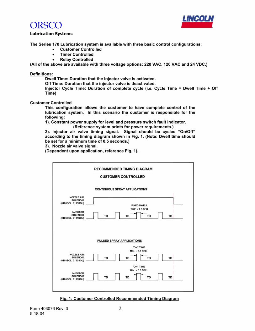
This configuration allows the customer to have complete control of the lubrication system. In this scenario the customer is responsible for the following: 1). Constant power supply for level and pressure switch fault indicator. (Reference system prints for power requirements.) 2). Injector air valve timing signal. Signal should be cycled “On/Off” according to the timing diagram shown in Fig. 1. (Note: Dwell time should be set for a minimum time of 0.5 seconds.) 3). Nozzle air valve signal. (Dependent upon application, reference Fig. 1).
RECOMMENDED TIMING DIAGRAM
CUSTOMER CONTROLLED
CONTINUOUS SPRAY APPLICATIONS
NOZZLE AIRSOLENOID
(0108SOL, 0113SOL)
INJECTORSOLENOID
(0106SOL, 0111SOL)
TD TD TD TD
FIXED DWELLTIME = 0.5 SEC.
INJECTORSOLENOID
(0106SOL, 0111SOL)
TD TD TD TD
NOZZLE AIRSOLENOID
(0108SOL, 0113SOL)
PULSED SPRAY APPLICATIONS
"ON" TIMEMIN. ~ 0.5 SEC.
"ON" TIMEMIN. ~ 0.5 SEC.
TD TD TD TD
Fig. 1: Customer Controlled Recommended Timing Diagram
ORSCO Lubrication Systems
Form 403076 Rev. 3 3 5-18-04
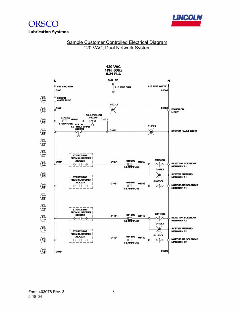
Sample Customer Controlled Electrical Diagram
120 VAC, Dual Network System
SYSTEM FAULT LIGHT
INJECTOR SOLENOIDNETWORK #1
NETWORK #1NOZZLE AIR SOLENOID
#16 AWG RED
L
#16 AWG GRN #16 AWG WHITE
120 VAC
GND PE N
0100FU4 AMP FUSE
01001
01011
0100
0101
0201
0301
0102FU
1 AMP FUSE
01021 01022
01022
OIL LEVEL OK0102FS
SETTING: 50 PSI0103PS
AIR ON
0106FU
1/4 AMP FUSE
1/4 AMP FUSE
0108FU
0103LT
R
0106SOL
0108SOL
FROM CUSTOMERSTART/STOP
XXXXCR
FROM CUSTOMERSTART/STOP
XXXXCR
01002
0100201011
01011 01061 01062
01081 01082
0111201111XXXXCR 0111FUINJECTOR SOLENOID
FROM CUSTOMERXXXXCR
START/STOP
0113FU
1/4 AMP FUSE
01131 01132
1/4 AMP FUSE
NOZZLE AIR SOLENOIDNETWORK #2
NETWORK #2
0113SOL
START/STOPFROM CUSTOMER
0111SOL
1PH, 60Hz0.31 FLA
06
0401
05
01
01
08
0901
07
01
01
0114
0113
10
11
0112
01
01
G
0107LT
NETWORK #1SYSTEM PUMPING
G
0112LT
NETWORK #2SYSTEM PUMPING
W
0103LT01002 POWER ON
LIGHT
ORSCO Lubrication Systems
Form 403076 Rev. 3 4 5-18-04
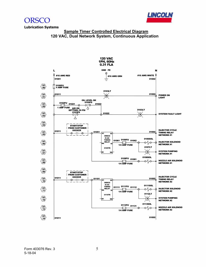
Timer Controlled
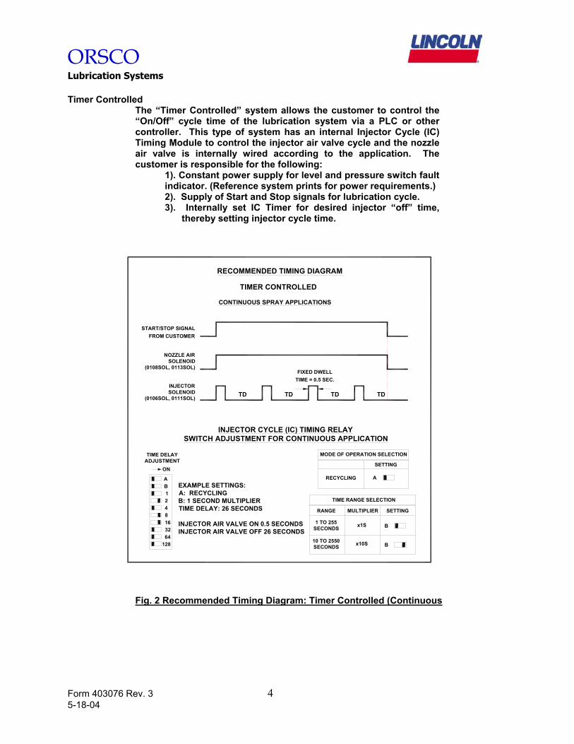
The “Timer Controlled” system allows the customer to control the “On/Off” cycle time of the lubrication system via a PLC or other controller. This type of system has an internal Injector Cycle (IC) Timing Module to control the injector air valve cycle and the nozzle air valve is internally wired according to the application. The customer is responsible for the following:
1). Constant power supply for level and pressure switch fault indicator. (Reference system prints for power requirements.) 2). Supply of Start and Stop signals for lubrication cycle. 3). Internally set IC Timer for desired injector “off” time,
thereby setting injector cycle time.
CONTINUOUS SPRAY APPLICATIONS
TIMER CONTROLLED
RECOMMENDED TIMING DIAGRAM
NOZZLE AIRSOLENOID
(0108SOL, 0113SOL)
INJECTORSOLENOID
(0106SOL, 0111SOL)
TD
FIXED DWELLTIME = 0.5 SEC.
TD TD TD
START/STOP SIGNALFROM CUSTOMER
TIME RANGE SELECTION
MODE OF OPERATION SELECTION
RECYCLING A
SETTING
INJECTOR CYCLE (IC) TIMING RELAYSWITCH ADJUSTMENT FOR CONTINUOUS APPLICATION
RANGE MULTIPLIER SETTING
B
B
1 TO 255SECONDS
10 TO 2550SECONDS
x1S
x10S
TIME DELAYADJUSTMENT
ON
AB1248
3216
64128
EXAMPLE SETTINGS:A: RECYCLINGB: 1 SECOND MULTIPLIERTIME DELAY: 26 SECONDS
INJECTOR AIR VALVE ON 0.5 SECONDSINJECTOR AIR VALVE OFF 26 SECONDS
Fig. 2 Recommended Timing Diagram: Timer Controlled (Continuous
ORSCO Lubrication Systems
Form 403076 Rev. 3 5 5-18-04
Sample Timer Controlled Electrical Diagram 120 VAC, Dual Network System, Continuous Application
SYSTEM FAULT LIGHT
INJECTOR SOLENOIDNETWORK #1
NETWORK #1NOZZLE AIR SOLENOID
#16 AWG RED
L
#16 AWG GRN #16 AWG WHITE
120 VAC
GND PE N
0100FU4 AMP FUSE
01001
01011
0100
0101
0201
0301
0102FU
1 AMP FUSE
01021 01022
01022
OIL LEVEL OK0102FS
SETTING: 50 PSI0103PS
AIR ON
0106FU
1/4 AMP FUSE
1/4 AMP FUSE
0108FU
0103LT
R
0106SOL
0108SOL
FROM CUSTOMERSTART/STOP
XXXXCR
01002
0100201011
01011 01051
01062
01081
1PH, 60Hz0.31 FLA
06
0401
05
01
01
08
0901
07
01
01
0114
0113
10
11
0112
01
01
G
0107LT
NETWORK #1SYSTEM PUMPING
W
0103LT01002
B1 NA
NA 18
A1 A2ORSCOIC-AC
TIMINGRELAY
0105TR
01061
01002 TIMING RELAYNETWORK #1
INJECTOR CYCLE
01111 01112RELAY INJECTOR SOLENOID
011310113FU
1/4 AMP FUSE
B1 NA
0110TR
NA 181/4 AMP FUSE
SYSTEM PUMPING
NOZZLE AIR SOLENOIDNETWORK #2
0113SOL
G
0112LT
NETWORK #2
NETWORK #2
01011 01101
FROM CUSTOMERSTART/STOP
XXXXCRA2A1
IC-ACTIMING
ORSCO
0111FU
INJECTOR CYCLE01002
0111SOL
TIMING RELAYNETWORK #2
POWER ONLIGHT
ORSCO Lubrication Systems
Form 403076 Rev. 3 6 5-18-04
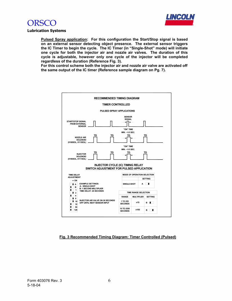
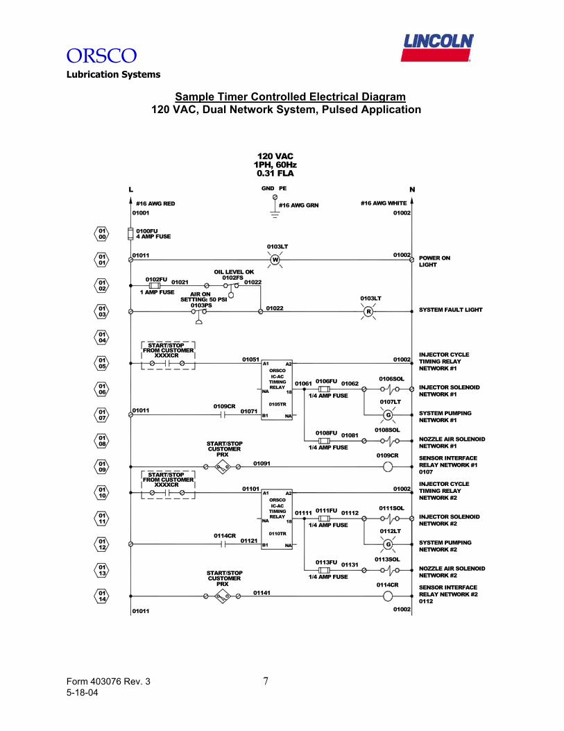
Pulsed Spray application: For this configuration the Start/Stop signal is based on an external sensor detecting object presence. The external sensor triggers the IC Timer to begin the cycle. The IC Timer (in “Single-Shot” mode) will initiate one cycle for both the injector air and nozzle air valves. The duration of this cycle is adjustable, however only one cycle of the injector will be completed regardless of the duration (Reference Fig. 3). For this control scheme both the injector air and nozzle air valve are activated off the same output of the IC timer (Reference sample diagram on Pg. 7).
INJECTORSOLENOID
(0106SOL, 0111SOL)
START/STOP SIGNALFROM EXTERNAL
SENSOR
NOZZLE AIRSOLENOID
(0108SOL, 0113SOL)
TD
TD TD
TD
"ON" TIMEMIN. ~ 0.5 SEC.
TD
TD
TD
TD
"ON" TIMEMIN. ~ 0.5 SEC.
SENSORSIGNAL
PULSED SPRAY APPLICATIONS
RECOMMENDED TIMING DIAGRAM
TIMER CONTROLLED
EXAMPLE SETTINGS:A: SINGLE-SHOTB: 1 SECOND MULTIPLIERTIME DELAY: 26 SECONDS
INJECTOR CYCLE (IC) TIMING RELAYSWITCH ADJUSTMENT FOR PULSED APPLICATION
128
1
16
6432
842
ON
BA
TIME DELAYADJUSTMENT
10 TO 2550SECONDS B
MULTIPLIER
SINGLE-SHOT
MODE OF OPERATION SELECTION
TIME RANGE SELECTION
1 TO 255SECONDS
RANGE SETTING
x10S
x1S B
SETTING
A
INJECTOR AIR VALVE ON 26 SECONDSOFF UNTIL NEXT SENSOR INPUT
Fig. 3 Recommended Timing Diagram: Timer Controlled (Pulsed)
ORSCO Lubrication Systems
Form 403076 Rev. 3 7 5-18-04
Sample Timer Controlled Electrical Diagram
120 VAC, Dual Network System, Pulsed Application
SYSTEM FAULT LIGHT
INJECTOR SOLENOIDNETWORK #1
NETWORK #1NOZZLE AIR SOLENOID
#16 AWG RED
L
#16 AWG GRN #16 AWG WHITE
120 VAC
GND PE N
0100FU4 AMP FUSE
01001
01011
0100
0101
0201
0301
0102FU
1 AMP FUSE
01021 01022
01022
OIL LEVEL OK0102FS
SETTING: 50 PSI0103PS
AIR ON
0106FU
1/4 AMP FUSE
1/4 AMP FUSE
0108FU
0103LT
R
0106SOL
0108SOL
01002
0100201011
01062
01081
1PH, 60Hz0.31 FLA
06
0401
05
01
01
08
0901
07
01
01
0114
0113
10
11
0112
01
01
G
0107LT
NETWORK #1SYSTEM PUMPING
W
0103LT01002
B1 NA
NA 18
A1 A2ORSCOIC-AC
TIMINGRELAY
0105TR
01061
01002 TIMING RELAYNETWORK #1
INJECTOR CYCLE
01111 01112RELAY INJECTOR SOLENOID
011310113FU
1/4 AMP FUSE
B1 NA
0110TR
NA 181/4 AMP FUSE
SYSTEM PUMPING
NOZZLE AIR SOLENOIDNETWORK #2
0113SOL
G
0112LT
NETWORK #2
NETWORK #2
A2A1
IC-ACTIMING
ORSCO
0111FU
INJECTOR CYCLE01002
0111SOL
TIMING RELAYNETWORK #2
01051
01011
CUSTOMERSTART/STOP
PRX01141 RELAY NETWORK #2
SENSOR INTERFACE0114CR
0112
0114CR01121
CUSTOMERSTART/STOP
PRX01091
0109CRRELAY NETWORK #1SENSOR INTERFACE
0107
010710109CR
FROM CUSTOMERXXXXCR
START/STOP
01101FROM CUSTOMER
XXXXCR
START/STOP
POWER ONLIGHT
ORSCO Lubrication Systems
Form 403076 Rev. 3 8 5-18-04
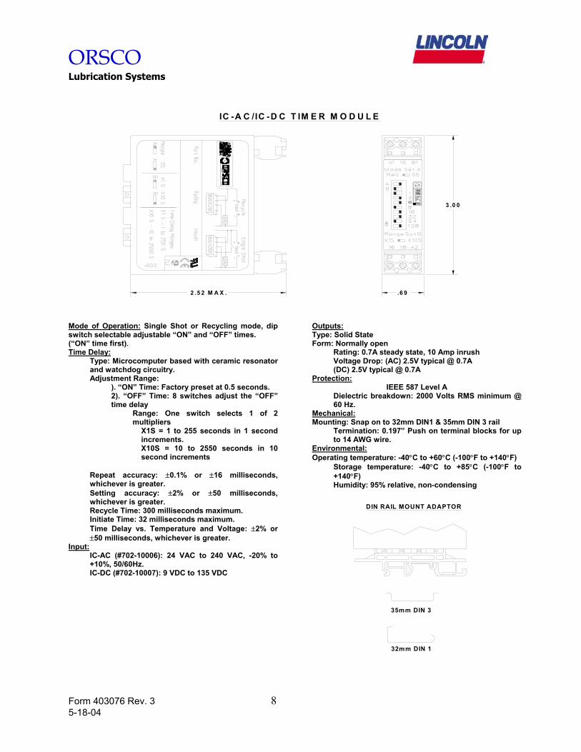
IC -A C /IC -D C T IM E R M O D U L E
3 .0 0
.6 92 .5 2 M A X .
Mode of Operation: Single Shot or Recycling mode, dip switch selectable adjustable “ON” and “OFF” times. (“ON” time first). Time Delay:
Type: Microcomputer based with ceramic resonator and watchdog circuitry. Adjustment Range:
). “ON” Time: Factory preset at 0.5 seconds. 2). “OFF” Time: 8 switches adjust the “OFF” time delay
Range: One switch selects 1 of 2 multipliers
X1S = 1 to 255 seconds in 1 second increments. X10S = 10 to 2550 seconds in 10 second increments
Repeat accuracy: ±0.1% or ±16 milliseconds, whichever is greater. Setting accuracy: ±2% or ±50 milliseconds, whichever is greater. Recycle Time: 300 milliseconds maximum. Initiate Time: 32 milliseconds maximum. Time Delay vs. Temperature and Voltage: ±2% or ±50 milliseconds, whichever is greater.
Input: IC-AC (#702-10006): 24 VAC to 240 VAC, -20% to +10%, 50/60Hz. IC-DC (#702-10007): 9 VDC to 135 VDC
Outputs: Type: Solid State Form: Normally open
Rating: 0.7A steady state, 10 Amp inrush Voltage Drop: (AC) 2.5V typical @ 0.7A (DC) 2.5V typical @ 0.7A
Protection: IEEE 587 Level A
Dielectric breakdown: 2000 Volts RMS minimum @ 60 Hz.
Mechanical: Mounting: Snap on to 32mm DIN1 & 35mm DIN 3 rail
Termination: 0.197” Push on terminal blocks for up to 14 AWG wire.
Environmental: Operating temperature: -40°C to +60°C (-100°F to +140°F)
Storage temperature: -40°C to +85°C (-100°F to +140°F) Humidity: 95% relative, non-condensing
DIN RAIL MOUNT ADAPTOR
35mm DIN 3
32mm DIN 1
ORSCO Lubrication Systems
Form 403076 Rev. 3 9 5-18-04
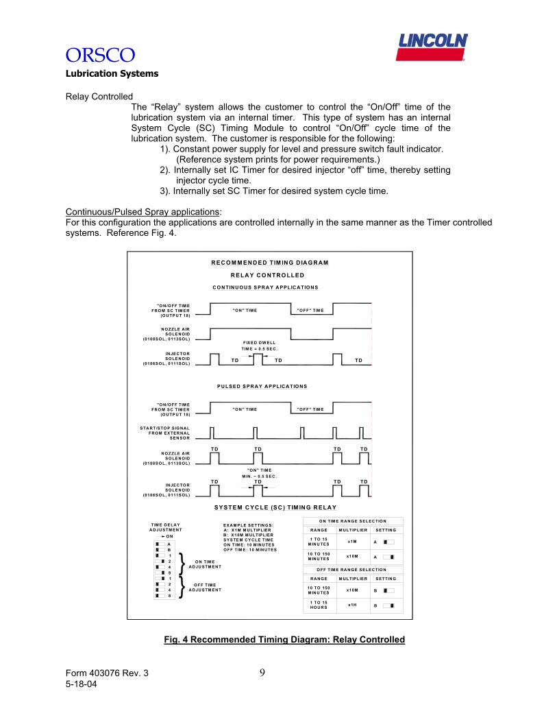
Relay Controlled
The “Relay” system allows the customer to control the “On/Off” time of the lubrication system via an internal timer. This type of system has an internal System Cycle (SC) Timing Module to control “On/Off” cycle time of the lubrication system. The customer is responsible for the following:
1). Constant power supply for level and pressure switch fault indicator. (Reference system prints for power requirements.) 2). Internally set IC Timer for desired injector “off” time, thereby setting
injector cycle time. 3). Internally set SC Timer for desired system cycle time.
Continuous/Pulsed Spray applications: For this configuration the applications are controlled internally in the same manner as the Timer controlled systems. Reference Fig. 4.
EXA M P LE S ETTIN G S:A : X1M M ULTIPLIERB : X10M M ULTIPLIERS YSTE M CY CLE TIM EO N TIM E: 10 M INU TESO FF T IM E : 10 M INUTES
S Y STEM C YC LE (SC ) T IM IN G R ELAY
1
842
TIM E D ELAYA DJU STM EN T
O N
BA
INJEC TO RSO LE NO ID
(0106S O L, 0111SO L)
N O ZZLE A IRSO LE NO ID
(0108S O L, 0113SO L)
S ETTING
1 TO 15HO UR S B
10 TO 150M INU TES
x1H
x10M
M ULTIPLIER
O FF TIM E RA NG E SE LE CTIO N
R ANG E
B
TD TD
FIX ED D W E LLTIM E = 0.5 SEC.
R EC O M M EN D ED TIM ING DIA G R AM
R ELA Y C O N TRO LLED
C O N TIN U O U S S PR A Y A PPLIC ATIO NS
TD
"O N " TIM E "O FF" TIM E
"O N " TIM E
P U LSE D S PR A Y A P PLICATIO NS
"O N " TIM EM IN . ~ 0.5 SEC .
"O N /O FF TIM EFRO M SC T IM ER
(O U TP U T 18)
S TA RT/STO P S IG NALFRO M EX TER NAL
SEN SO R
TD
"O FF" TIM E
TD
INJEC TO RSO LE NO ID
(0106S O L, 0111SO L)
TD TD
N O ZZLE A IRSO LE NO ID
(0108S O L, 0113SO L)
TD
TD TD
TD
"O N /O FF TIM EFRO M SC T IM ER
(O U TP U T 18)
x10M
x1M
O N TIM E R AN G E S ELEC TIO N
M ULTIPLIER
10 TO 150M INU TES
1 TO 15M INU TES
R ANG E
A
A
S ETTING
1248
O N TIM EA D JU STM ENT}
} O FF TIM EA D JU STM ENT
Fig. 4 Recommended Timing Diagram: Relay Controlled
ORSCO Lubrication Systems
Form 403076 Rev. 3 10 5-18-04
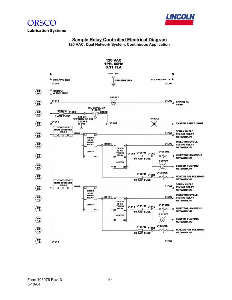
Sample Relay Controlled Electrical Diagram
120 VAC, Dual Network System, Continuous Application
SYSTEM FAULT LIGHT
INJECTOR SOLENOIDNETWORK #1
NETWORK #1NOZZLE AIR SOLENOID
#16 AWG RED
L
#16 AWG GRN #16 AWG WHITE
120 VAC
GND PE N
0100FU4 AMP FUSE
01001
01011
0100
0101
0201
0301
0102FU
1 AMP FUSE
01021 01022
01022
OIL LEVEL OK0102FS
SETTING: 50 PSI0103PS
AIR ON
0106FU
1/4 AMP FUSE
1/4 AMP FUSE
0108FU
0103LT
R
0106SOL
0108SOL
01002
0100201011
01011
01051
01062
01081
1PH, 60Hz0.31 FLA
06
0401
05
01
01
08
0901
07
01
01
0114
0113
10
11
0112
01
01
G
0107LT
NETWORK #1SYSTEM PUMPING
W
0103LT01002
B1 NA
NA 18
A1 A2ORSCOIC-AC
TIMINGRELAY
0105TR
01061
01002 TIMING RELAYNETWORK #1
INJECTOR CYCLE
01111 01112RELAY INJECTOR SOLENOID
011310113FU
1/4 AMP FUSE
B1 NA
0110TR
NA 181/4 AMP FUSE
SYSTEM PUMPING
NOZZLE AIR SOLENOIDNETWORK #2
0113SOL
G
0112LT
NETWORK #2
NETWORK #2
01101A2A1
IC-ACTIMING
ORSCO
0111FU
INJECTOR CYCLE01002
0111SOL
TIMING RELAYNETWORK #2
RELAY
B1 NA
0104TR
NA 18
A2A1
TIMINGSC-ACORSCO
SPRAY CYCLETIMING RELAYNETWORK #1
B1 NA
A2A1
0109TR
SC-ACTIMING
ORSCO
RELAYNA 18
TIMING RELAYNETWORK #2
SPRAY CYCLE
01002
01002
START/STOP
XXXCRFROM CUSTOMER
01041
CUSTOMERXXXCR
START/STOPFROM
01091
POWER ONLIGHT
ORSCO Lubrication Systems
Form 403076 Rev. 3 11 5-18-04
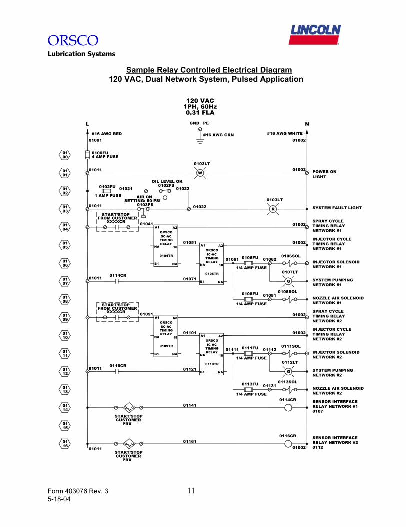
Sample Relay Controlled Electrical Diagram
120 VAC, Dual Network System, Pulsed Application
SYSTEM FAULT LIGHT
INJECTOR SOLENOIDNETWORK #1
NETWORK #1NOZZLE AIR SOLENOID
#16 AWG RED
L
#16 AWG GRN #16 AWG WHITE
120 VAC
GND PE N
0100FU4 AMP FUSE
01001
01011
0100
0101
0201
0301
0102FU
1 AMP FUSE
01021 01022
01022
OIL LEVEL OK0102FS
SETTING: 50 PSI0103PS
AIR ON
0106FU
1/4 AMP FUSE
1/4 AMP FUSE
0108FU
0103LT
R
0106SOL
0108SOL
01002
0100201011
01062
01081
1PH, 60Hz0.31 FLA
06
0401
05
01
01
08
0901
07
01
01
0114
0113
10
11
0112
01
01
G
0107LT
NETWORK #1SYSTEM PUMPING
W
0103LT01002
B1 NA
NA 18
A1 A2ORSCOIC-AC
TIMINGRELAY
0105TR
01061
01002 TIMING RELAYNETWORK #1
INJECTOR CYCLE
01111 01112RELAY INJECTOR SOLENOID
011310113FU
1/4 AMP FUSE
B1 NA
0110TR
NA 181/4 AMP FUSE
SYSTEM PUMPING
NOZZLE AIR SOLENOIDNETWORK #2
0113SOL
G
0112LT
NETWORK #2
NETWORK #2
A2A1
IC-ACTIMING
ORSCO
0111FU
INJECTOR CYCLE01002
0111SOL
TIMING RELAYNETWORK #2
01071
RELAY
B1 NA
0104TR
NA 18
A2A1
TIMINGSC-ACORSCO
SPRAY CYCLETIMING RELAYNETWORK #1
01002
01051
B1 NA
A1 A2
0109TR
SC-ACORSCO
TIMINGRELAY
NA 1801101
TIMING RELAYNETWORK #2
01002SPRAY CYCLE
CUSTOMERPRX
START/STOP
01011
01011
0116
0115
XXXXCR
START/STOPFROM CUSTOMER
01011
01041
FROM CUSTOMERXXXXCR
START/STOP
01091
START/STOPCUSTOMER
PRX
SENSOR INTERFACE
0107RELAY NETWORK #1
RELAY NETWORK #2SENSOR INTERFACE
0112
0114CR
01011 0116CR01121
0114CR01141
011610116CR
POWER ONLIGHT
ORSCO Lubrication Systems
Form 403076 Rev. 3 12 5-18-04
3.00
2.52 MAX. .69
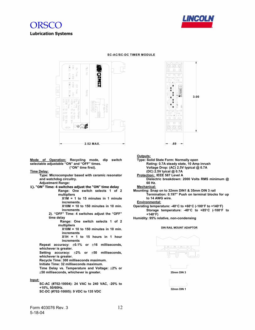
SC-AC/SC-DC TIMER MODULE
Mode of Operation: Recycling mode, dip switch selectable adjustable “ON” and “OFF” times. (“ON” time first). Time Delay:
Type: Microcomputer based with ceramic resonator and watchdog circuitry. Adjustment Range:
1). “ON” Time: 4 switches adjust the “ON” time delay Range: One switch selects 1 of 2 multipliers
X1M = 1 to 15 minutes in 1 minute increments. X10M = 10 to 150 minutes in 10 min. increments
2). “OFF” Time: 4 switches adjust the “OFF” time delay
Range: One switch selects 1 of 2 multipliers
X10M = 10 to 150 minutes in 10 min. increments X1H = 1 to 15 hours in 1 hour increments
Repeat accuracy: ±0.1% or ±16 milliseconds, whichever is greater. Setting accuracy: ±2% or ±50 milliseconds, whichever is greater. Recycle Time: 300 milliseconds maximum. Initiate Time: 32 milliseconds maximum. Time Delay vs. Temperature and Voltage: ±2% or ±50 milliseconds, whichever is greater.
Input:
SC-AC (#702-10004): 24 VAC to 240 VAC, -20% to +10%, 50/60Hz. SC-DC (#702-10005): 9 VDC to 135 VDC
Outputs: Type: Solid State Form: Normally open
Rating: 0.7A steady state, 10 Amp inrush Voltage Drop: (AC) 2.5V typical @ 0.7A (DC) 2.5V tyical @ 0.7A
Protection: IEEE 587 Level A Dielectric breakdown: 2000 Volts RMS minimum @ 60 Hz.
Mechanical: Mounting: Snap on to 32mm DIN1 & 35mm DIN 3 rail
Termination: 0.197” Push on terminal blocks for up to 14 AWG wire.
Environmental: Operating temperature: -40°C to +60°C (-100°F to +140°F)
Storage temperature: -40°C to +85°C (-100°F to +140°F)
Humidity: 95% relative, non-condensing
DIN RAIL MOUNT ADAPTOR
35mm DIN 3
32mm DIN 1
ORSCO Lubrication Systems
Form 403076 Rev. 3 13 5-18-04
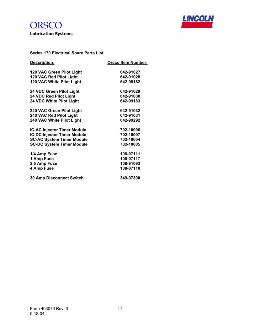
Series 170 Electrical Spare Parts List Description: Orsco Item Number: 120 VAC Green Pilot Light 642-91027 120 VAC Red Pilot Light 642-91028 120 VAC White Pilot Light 642-99182 24 VDC Green Pilot Light 642-91029 24 VDC Red Pilot Light 642-91030 24 VDC White Pilot Light 642-99183 240 VAC Green Pilot Light 642-91032 240 VAC Red Pilot Light 642-91031 240 VAC White Pilot Light 642-99292 IC-AC Injector Timer Module 702-10006 IC-DC Injector Timer Module 702-10007 SC-AC System Timer Module 702-10004 SC-DC System Timer Module 702-10005 1/4 Amp Fuse 108-07111 1 Amp Fuse 108-07117 2.5 Amp Fuse 108-91093 4 Amp Fuse 108-07110 30 Amp Disconnect Switch 349-07300

ORSCO Lubrication Systems
50650 Corporate Drive, Shelby Township, MI 48315 (586)997-0300 phone -- (586)997-2072 fax
www.lincolnindustrial.com [email protected]