Embed Size (px)
Citation preview

VEIKI-VNL ELECTRIC LARGE LABORATORIES Ltd.
No. 8420/VNL Page 1 of 13
Budapest, 13th February, 2015
................................ Lajos Tóth
responsible for the test
................................ Norbert Menyhért
supervised by
................................ Dr. László Varga managing director
1158 Budapest, Vasgolyó u. 2-4., HUNGARY Phone: +36-1-417 3157 Fax: +36-1-417 3163
E-mail: [email protected] www. vnl.hu
TYPE TEST REPORT
Test object: All Aluminium Alloy Conductor (AAAC)
Designation: 181 mm2 All Aluminium Alloy Conductor (Code: 181-AL3)
Manufacturer: BMET Energy Telecom Industry and Trade LLC.
Region: Oromia Subcity: Finfine Special Zone City:
Sebeta Woreda: Sebeta-Hawas Kebele: Dima Guranda
P.O Box No: 20206/1000
ETHIOPIA
Tested for: BMET ENERJİ TELEKOM SAN. VE TİC. A.Ş.
Yeşilyurt Mah. Orkide Cad. Eresin Apt. No : 12 Daire No :11 , Kat 5
34149-Bakırköy
İSTANBUL/TURKEY
Date of tests: 21st January 2015 – 05th February 2015
Tested by: VEIKI-VNL Ltd. – Budapest – HUNGARY
Project ID: NAL-33/2014
Order/Contract: 1066/2014, 19th November 2014
Test specification: EN 50182: 2001 Conductors for overhead lines - Round wire concentric lay stranded conductors
Tests performed: The test object, constructed in accordance with the description, drawings and photographs incorporated in this report has been subjected to the following tests:
Stress-Strain curves (Clause 6.4.7 and Annex C)
Tensile breaking strength (Clause 6.4.8 and Annex C)
DC resistance measurement at 25 °C, 50 °C and 75 °C conductor temperatures
Test results: The tested conductor type AAAC 181 mm2 (Code: 181-AL3) fulfilled the requirements of the relevant standards.
This Type Test Report has been issued by VEIKI-VNL Ltd. in accordance with above mentioned specification.
The Report applies only to the test object. The responsibility for conformity of any product having the same designations with that tested rests with the Manufacturer.
This Report comprises 14 sheets in total (13 numbered pages and 1 datasheet).
Only integral reproduction of this document is permitted without written permission from VEIKI-VNL Ltd.
VEIKI-VNL Ltd. is an independent testing laboratory. Member of Short-circuit Testing Liaison (STL).
VEIKI-VNL Ltd. is a testing laboratory, accredited by NAT (Hungarian Accreditation Board) under registration number NAT-1-1251/2011.
DRAFT

VEIKI-VNL ELECTRIC LARGE LABORATORIES Ltd.
No. 8420/VNL Page 2 of 13
TEST CERTIFICATES OR REPORTS ISSUED BY VEIKI-VNL LTD. Type Test Certificate of Complete Type Test This certificate provides the verification of all the rated characteristics of the equipment as assigned by the manufacturer, by means of the performance of all type tests specified by the standards.
Type Test Certificate of Dielectric Performance This certificate provides the verification of all dielectric ratings, by means of the performance of the appropriate type tests specified by the standards.
Type Test Certificate of Temperature-Rise Performance This certificate provides the verification of temperature-rise limits together with measurement of the main circuit resistance, by means of the performance of the appropriate type tests specified by the standards.
Type Test Certificate of Short-Circuit / Making and Breaking Performance This certificate provides the verification of rated characteristics with respect short-circuit and/or making and breaking performance, by means of the performance of the appropriate type tests specified by the standards.
Type Test Certificate of Switching Performance This certificate provides the verification of the switching ratings (e.g. capacitive current), by means of the performance of the appropriate type tests specified by the standards.
Prototype Test Report Prototype tests are required to verify the suitability of the materials and method of manufacture for composite insulators defined by relevant ANSI standards.
Design Test Report According to IEC standard: The design tests are intended to verify the suitability of the design, materials and method of manufacture (technology) of composite insulators.
According to ANSI standard: The design tests are intended to verify the insulators electrical and mechanical characteristics that depend on its size and shape.
Type Test Report This report provides the verification of the rated characteristics of the equipment as assigned by the manufacturer, by means of the performance of the appropriate type tests specified by the standards, for type tests not indicated above.
Development Test Report This report is issued when the test is intended only to provide the Client with information about the performance of the equipment. The tests are performed in accordance with relevant standards, but are not intended to verify compliance of the equipment.
Control Test Report This report is issued for tests performed on equipment in service, or removed from service. Tests are performed, and compliance is evaluated in accordance with relevant standards.
Test Report Test report is issued in all cases not listed above.
DRAFT

VEIKI-VNL ELECTRIC LARGE LABORATORIES Ltd.
No. 8420/VNL Page 3 of 13
Ratings/characteristics assigned by the manufacturer:
Test object: All Aluminium Alloy Conductor (AAAC)
Designation: 181 mm2 All Aluminium Alloy Conductor (Code: 181-AL3) Manufacturer: BMET
Structure:
Centre: 1 × Ø3.48mm Aluminium Alloy wire (Al-Mg-Si) Layer 1: 6 × Ø3.48mm Aluminium Alloy wire (Al-Mg-Si) Layer 2: 12 × Ø3.48mm Aluminium Alloy wire (Al-Mg-Si)
Cross-sectional area: 180.7 mm2
Conductor Diameter: 17.4 mm Rated Tensile Strength (RTS): 53.31 kN Modulus of Elasticity (E): 57 kN/mm2 Nominal conductor mass: 496.1 kg/km DC resistance at 20 °C: 0.1830 Ω/km
The tests were carried out in accordance with the following standards:
EN 50182: 2001 Conductors for overhead lines – Round wire concentric lay stranded conductors
Requirements of manufacturer or purchaser:
DC resistance measurement at 25 °C, 50 °C and 75 °C conductor temperature
List of manufacturer's drawings for identification of the test object:
Technical Datasheet - 181 mm2 All Aluminium Alloy Conductor
Present at the test in charge of manufacturer or purchaser:
- DRAFT

VEIKI-VNL ELECTRIC LARGE LABORATORIES Ltd.
No. 8420/VNL Page 4 of 13
TESTS PERFORMED ON THE APPARATUS
No. Description Relevant clauses of the standard 1 Stress-Strain curves EN 50182: 2001 Clause 6.4.7, Annex C 2 Tensile breaking strength EN 50182: 2001 Clause 6.4.8, Annex C 3 DC resistance measurement Client's requirement
DESCRIPTION OF THE TESTS
1. Stress-Strain curves
1.1. Test method and parameters
Stress–strain test was carried out on overhead line conductor type AAAC 181 mm2 (Photo 1) in accordance with standard EN 50182 Clause 6.4.7 and Annex C. The ends of the conductor specimens were terminated with epoxy-resin dead-end and fixed in the end fittings (Photo 3). The test was performed in a tensile machine; with gauge length of 10.08 m. The conductor was tensioned according to the following table:
Table 1: Loading schedule for stress-strain test
Initial load (5% of RTS):
2.7 kN To straighten the conductor and set the strain gage to zero.
Load (30% of RTS): 16.0 kN 30 min, then released to initial load. Load (50% of RTS): 26.7 kN 60 min, then released to initial load. Load (70% of RTS): 37.3 kN 60 min, then released to initial load. Load (85% of RTS): 45.3 kN 60 min, then released to initial load.
During the test the conductor sample was supported along its length to keep the conductor straight and minimize the sag. The test set-up for the stress-strain test is shown in Figure 1 and on Photo 2. The test was carried out in a temperature-controlled laboratory at 20°C±2°C.
Figure 1
Test arrangement
DRAFT

VEIKI-VNL ELECTRIC LARGE LABORATORIES Ltd.
No. 8420/VNL Page 5 of 13
1.2. Test results
The modulus of elasticity of the conductor was determined from the Force-Elongation curve by simple linear regression. Figure 2 shows the lines of best fit placed on the unloading segments of the curve.
Figure 2
Lines of best fit placed on the unloading segments
The Modulus of Elasticity obtained at 30, 50, 70 and 85% RTS are summarised in Table 2.
Table 2: Modulus of elasticity
Load Line of best fit ( y m x b )
Slope (m)
Modulus of Elasticity
( 0lE mA
)
30% RTS 1 1.0577 2.5318y x 1.0577 58.36 2
kN
mm
50% RTS 2 1.1142 5.3276y x 1.1142 61.48 2
kN
mm
70% RTS 3 1.1246 8.2108y x 1.1246 62.05 2
kN
mm
85% RTS 4 1.1347 11.628y x 1.1347 62.61 2
kN
mm
DRAFT

VEIKI-VNL ELECTRIC LARGE LABORATORIES Ltd.
No. 8420/VNL Page 6 of 13
The measured curves were corrected to cross zero by 0.03662% strain for the conductor. The corrected force-strain curves of the conductor are plotted in Figure 3.
Figure 3 Stress-Strain curve (Conductor)
The stress-strain values obtained at the end of each hold period are summarized in Table 3. Table 3: Stress and strain of the conductor
Load Strain
[%]
Stress of Conductor
[N/mm2]
30% RTS 0.2091 88.4837
50% RTS 0.3255 147.8085
70% RTS 0.4398 206.3033
85% RTS 0.5341 250.5755
The initial curve was obtained by fitting 4th order polynomial curve to above points. The coefficients are as follows:
- Conductor: y = -98.385x4 – 493.61x3 + 551.86x2 + 330.21x where: x: strain [%] y: stress [N/mm2], calculated with the cross-sectional area of the whole conductor
DRAFT

VEIKI-VNL ELECTRIC LARGE LABORATORIES Ltd.
No. 8420/VNL Page 7 of 13
The coefficients of the regression line fitted to the unloading segment of the stress-strain curves are as follows:
- Conductor: y = 653.03x – 99.166 where: x: strain [%] y: stress [N/mm2], calculated with the cross-sectional area of the whole conductor
2. Tensile breaking strength
2.1. Test method and parameters
The verification of tensile breaking strength was carried out on overhead line conductor type AAAC 181 mm2 in accordance with standard EN 50182 Clause 6.4.8 and Annex C. The test was carried on the same conductor specimen, which was subjected to stress-strain test.
2.2. Test results
The tensile specimen broke at the load of 61.74 kN. This value is higher than 50.6 kN (95 % of the 53.31 kN RTS), which is the acceptance criterion of the relevant standard. Based on the test results; the conductor AAAC 181 mm2 fulfilled the requirements of tensile breaking strength.
The obtained Force-Elongation curve is shown in Figure 4. The fractured wires are shown on Photo 4.
Figure 4
Tensile test of the conductor
DRAFT

VEIKI-VNL ELECTRIC LARGE LABORATORIES Ltd.
No. 8420/VNL Page 8 of 13
3. DC resistance measurement
3.1. Test method and parameters
The DC resistance measurement was carried out on overhead line conductor type AAAC 181 mm2 according to the test procedure agreed with Client. The conductor was placed in a 6 m long test span. The conductor was fixed by electrically ant thermally isolated fittings; the applied force was 10.7 kN (20% of RTS). The ends of the conductor were led to the power transformer and connected by bolted current clamps. The current was measured by CT and a data logger. Conductor temperature was measured by thermocouples installed under the outer layer at ends and middle of the tested section. The currents were applied to the conductor until its temperature reached steady state condition. The DC resistance measurement was made by a DC micro-ohmmeter (4-wire method). The voltage drop was measured in a 3 m long section at the middle of the span. The DC resistance measurement was performed at 25°C, 50°C and 75°C conductor temperature. The test arrangement is shown in Figure 5.
Figure 5 Test circuit diagram for DC resistance measurement
3 m
DRAFT

VEIKI-VNL ELECTRIC LARGE LABORATORIES Ltd.
No. 8420/VNL Page 9 of 13
3.2. Test results
The DC resistance of the conductor measured at the temperature of 20.2°C was as the following:
_3 541.8mR 541.8
180.6 0.18063
Rm m km
The resistance value obtained was corrected to 20°C by the following formula:
20 320
0.18060.1803
1 20 1 3.6 10 20.4 20
RR
km
where
R
is the measured resistance
is the temperature in degree Celsius
20 is the thermal coefficient of resistance ( )
The measured resistance of the conductor (0.1803 Ω/km) was lower than the specified maximum 0.1830 Ω/km; therefore the conductor met the DC resistance requirement of the data sheet. The DC resistances measured at 25°C, 50°C and 75°C conductor temperatures are summarized in Table 4. Table 4: Results of DC resistance measurement
Average Temperature
[°C]
Heating Current
[A]
Measured DC-Resistance
[µΩ]
DC-Resistance [Ω/km]
20.4 - 541.80 0.1806
26.1 112.5 550.67 0.1836
50.6 289.3 600.01 0.2000
74.7 396.8 648.14 0.2160
The conductor temperature and the heating current are plotted in Figure 6.
DRAFT

VEIKI-VNL ELECTRIC LARGE LABORATORIES Ltd.
No. 8420/VNL Page 10 of 13
Figure 6
Conductor temperature and heating current
DRAFT

VEIKI-VNL ELECTRIC LARGE LABORATORIES Ltd.
No. 8420/VNL Page 11 of 13
Uncertainty of measurements
Current measurement: ± 1 % Temperature measurement: ± 2 °C Tensile force measurement: ± 1 % Resistance measurement: ± 0.2 %
The uncertainty values given in this report are the standard deviation values multiplied by k=2. Measurement uncertainty was estimated according to the method described in the EA-4/02 document. Measuring devices used for the tests:
Designation Manufacturer Type S/N:
Data Logger FLUKE 2635A 2443009
Current Transformer TETTEX 4724 103361
DC Microohm-meter VEIKI-VNL MO-1 001
Power Analyser HIOKI 3193 05021 4964
Load Cell TENZI TCD-S-100kN 101102
Tensile test machine (300 kN) BARABÁS Mérnökiroda
Kft. KSZ 001/2011
DRAFT
VEIKI-VNL ELECTRIC LARGE LABORATORIES Ltd.
No. 8420/VNL Page 12 of 13
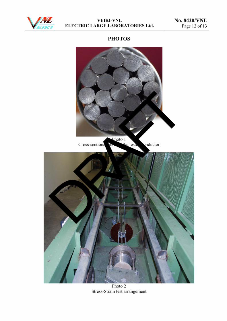
PHOTOS
Photo 1
Cross-sectional view of the tested conductor
Photo 2
Stress-Strain test arrangement
DRAFT

VEIKI-VNL ELECTRIC LARGE LABORATORIES Ltd.
No. 8420/VNL Page 13 of 13
Photo 3
Dead-end fitting
Photo 4
Fractured wires after the tensile breaking test
DRAFT

Type AAACCode 181-AL3Old Coed ASHAccording to regulation BS EN 50182_2001Size/nominal sectional area mm² 181Number of Wires 19Wire Diameter mm² 3.48Ultimate tensile strength (before stranding) N/mm² 295Conductivity at 20²C % IACS 53Calculated Area mm² 180.7Minumum breaking strength kN 53.31Conductor Diameter mm 17.4Standard weight kg/km 496.1Calculated resistance 20°C (DC) Ohm/km 0.1830Modulus of elasticity (Final) N/mm² 57000Coefficient of linear expansion per °C 23*10^-6Lay Ratio Outer: 10-14 Second:10-16Direction of Lay Outer: Right Second:LeftLength of each reel m 2000Reel Type mm 1300 * 650 * 880Net weight per drum (without grease) kg 992Gross weight per drum kg 1252
TECHNICAL DATASHEET
181 mm² All Aluminum Alloy Conductor
DRAFT