Embed Size (px)
Citation preview

Relion® 670 series
Generator protection REG670 2.0 IECType test certificate

Document ID: 1MRK502054-TENIssued: July 2016
Revision: BProduct version: 2.0
© Copyright 2014 ABB. All rights reserved
Copyright
This document and parts thereof must not be reproduced or copied without writtenpermission from ABB, and the contents thereof must not be imparted to a third party,nor used for any unauthorized purpose.
The software and hardware described in this document is furnished under a license andmay be used or disclosed only in accordance with the terms of such license.
This product includes software developed by the OpenSSL Project for use in theOpenSSL Toolkit. (http://www.openssl.org/)
This product includes cryptographic software written/developed by: Eric Young([email protected]) and Tim Hudson ([email protected]).
TrademarksABB and Relion are registered trademarks of the ABB Group. All other brand orproduct names mentioned in this document may be trademarks or registeredtrademarks of their respective holders.
WarrantyPlease inquire about the terms of warranty from your nearest ABB representative.
Disclaimer
The data, examples and diagrams in this manual are included solely for the concept orproduct description and are not to be deemed as a statement of guaranteed properties.All persons responsible for applying the equipment addressed in this manual mustsatisfy themselves that each intended application is suitable and acceptable, includingthat any applicable safety or other operational requirements are complied with. Inparticular, any risks in applications where a system failure and/or product failurewould create a risk for harm to property or persons (including but not limited topersonal injuries or death) shall be the sole responsibility of the person or entityapplying the equipment, and those so responsible are hereby requested to ensure thatall measures are taken to exclude or mitigate such risks.
This document has been carefully checked by ABB but deviations cannot becompletely ruled out. In case any errors are detected, the reader is kindly requested tonotify the manufacturer. Other than under explicit contractual commitments, in noevent shall ABB be responsible or liable for any loss or damage resulting from the useof this manual or the application of the equipment.

Conformity
This product complies with the directive of the Council of the European Communitieson the approximation of the laws of the Member States relating to electromagneticcompatibility (EMC Directive 2004/108/EC) and concerning electrical equipment foruse within specified voltage limits (Low-voltage directive 2006/95/EC). Thisconformity is the result of tests conducted by ABB in accordance with the productstandard EN 60255-26 for the EMC directive, and with the product standards EN60255-1 and EN 60255-27 for the low voltage directive. The product is designed inaccordance with the international standards of the IEC 60255 series.
Table of contents
Section 1 General.............................................................................3Definitions...........................................................................................3
Section 2 Energizing quantities, rated values and limits.................. 5Analog inputs......................................................................................5Auxiliary DC voltage........................................................................... 6Binary inputs and outputs................................................................... 7Influencing factors............................................................................ 12Influencing factors, injection equipment........................................... 13
Section 3 Type tests according to standards................................. 15Injection equipment.......................................................................... 17
Section 4 Control............................................................................19
Section 5 Differential protection..................................................... 23
Section 6 Impedance protection.....................................................25
Section 7 Current protection...........................................................29
Section 8 Voltage protection.......................................................... 39
Section 9 Frequency protection......................................................43
Section 10 Multipurpose protection..................................................45
Section 11 Secondary system supervision.......................................49
Section 12 Logic...............................................................................51
Section 13 Monitoring.......................................................................53
Section 14 Metering......................................................................... 59
Section 15 Station communication...................................................61
Section 16 Remote communication..................................................65
Section 17 Hardware........................................................................67IED....................................................................................................67Electrical safety................................................................................ 67Connection system........................................................................... 68Injection equipment hardware.......................................................... 68
Table of contents
1Type test certificate
Section 18 Basic IED functions........................................................ 71
Section 19 Inverse characteristics....................................................73
Table of contents
2Type test certificate
Section 1 General
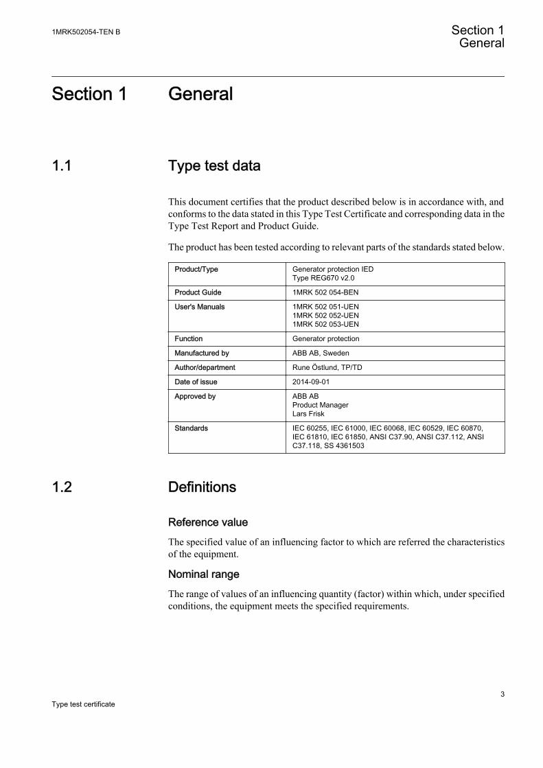
1.1 Type test data
This document certifies that the product described below is in accordance with, andconforms to the data stated in this Type Test Certificate and corresponding data in theType Test Report and Product Guide.
The product has been tested according to relevant parts of the standards stated below.
Product/Type Generator protection IEDType REG670 v2.0
Product Guide 1MRK 502 054-BEN
User's Manuals 1MRK 502 051-UEN1MRK 502 052-UEN1MRK 502 053-UEN
Function Generator protection
Manufactured by ABB AB, Sweden
Author/department Rune Östlund, TP/TD
Date of issue 2014-09-01
Approved by ABB ABProduct ManagerLars Frisk
Standards IEC 60255, IEC 61000, IEC 60068, IEC 60529, IEC 60870,IEC 61810, IEC 61850, ANSI C37.90, ANSI C37.112, ANSIC37.118, SS 4361503
1.2 Definitions
Reference valueThe specified value of an influencing factor to which are referred the characteristicsof the equipment.
Nominal rangeThe range of values of an influencing quantity (factor) within which, under specifiedconditions, the equipment meets the specified requirements.
1MRK502054-TEN B Section 1General
3Type test certificate
Operative rangeThe range of values of a given energizing quantity for which the equipment, underspecified conditions, is able to perform its intended functions according to thespecified requirements.
Section 1 1MRK502054-TEN BGeneral
4Type test certificate
Section 2 Energizing quantities, rated values andlimits
2.1 Analog inputs
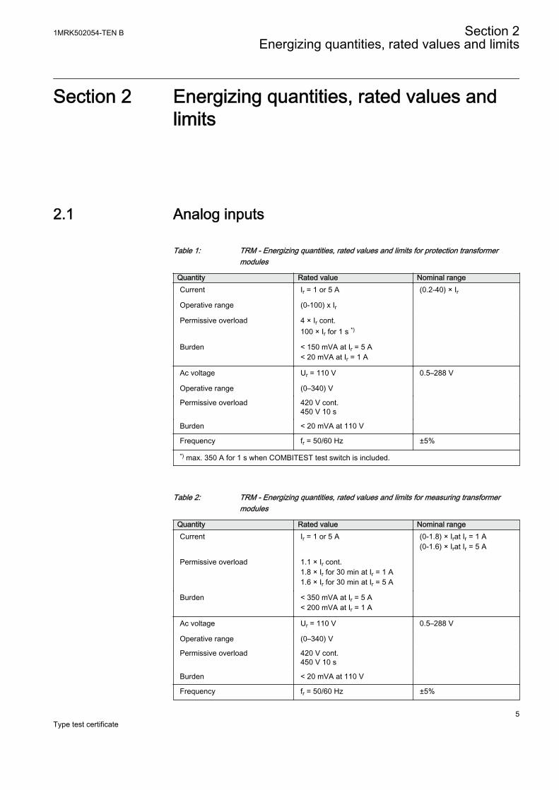
Table 1: TRM - Energizing quantities, rated values and limits for protection transformermodules
Quantity Rated value Nominal rangeCurrent Ir = 1 or 5 A (0.2-40) × Ir
Operative range (0-100) x Ir
Permissive overload 4 × Ir cont.100 × Ir for 1 s *)
Burden < 150 mVA at Ir = 5 A< 20 mVA at Ir = 1 A
Ac voltage Ur = 110 V 0.5–288 V
Operative range (0–340) V
Permissive overload 420 V cont.450 V 10 s
Burden < 20 mVA at 110 V
Frequency fr = 50/60 Hz ±5%
*) max. 350 A for 1 s when COMBITEST test switch is included.
Table 2: TRM - Energizing quantities, rated values and limits for measuring transformermodules
Quantity Rated value Nominal rangeCurrent Ir = 1 or 5 A (0-1.8) × Irat Ir = 1 A
(0-1.6) × Irat Ir = 5 A
Permissive overload 1.1 × Ir cont.1.8 × Ir for 30 min at Ir = 1 A1.6 × Ir for 30 min at Ir = 5 A
Burden < 350 mVA at Ir = 5 A< 200 mVA at Ir = 1 A
Ac voltage Ur = 110 V 0.5–288 V
Operative range (0–340) V
Permissive overload 420 V cont.450 V 10 s
Burden < 20 mVA at 110 V
Frequency fr = 50/60 Hz ±5%
1MRK502054-TEN B Section 2Energizing quantities, rated values and limits
5Type test certificate
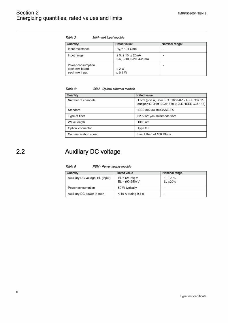
Table 3: MIM - mA input module
Quantity: Rated value: Nominal range:Input resistance Rin = 194 Ohm -
Input range ± 5, ± 10, ± 20mA0-5, 0-10, 0-20, 4-20mA
-
Power consumptioneach mA-boardeach mA input
£ 2 W£ 0.1 W
-
Table 4: OEM - Optical ethernet module
Quantity Rated valueNumber of channels 1 or 2 (port A, B for IEC 61850-8-1 / IEEE C37.118
and port C, D for IEC 61850-9-2LE / IEEE C37.118)
Standard IEEE 802.3u 100BASE-FX
Type of fiber 62.5/125 mm multimode fibre
Wave length 1300 nm
Optical connector Type ST
Communication speed Fast Ethernet 100 Mbit/s
2.2 Auxiliary DC voltage
Table 5: PSM - Power supply module
Quantity Rated value Nominal rangeAuxiliary DC voltage, EL (input) EL = (24-60) V
EL = (90-250) VEL ±20%EL ±20%
Power consumption 50 W typically -
Auxiliary DC power in-rush < 10 A during 0.1 s -
Section 2 1MRK502054-TEN BEnergizing quantities, rated values and limits
6Type test certificate
2.3 Binary inputs and outputs
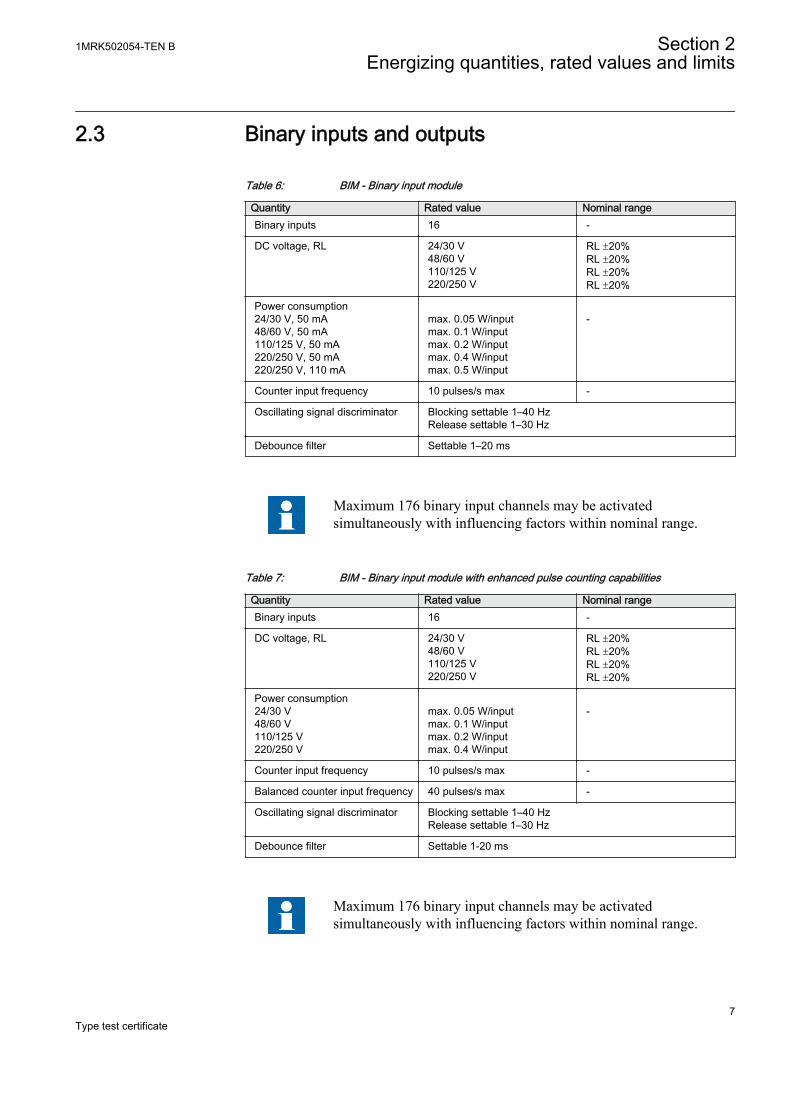
Table 6: BIM - Binary input module
Quantity Rated value Nominal rangeBinary inputs 16 -
DC voltage, RL 24/30 V48/60 V110/125 V220/250 V
RL ±20%RL ±20%RL ±20%RL ±20%
Power consumption24/30 V, 50 mA48/60 V, 50 mA110/125 V, 50 mA220/250 V, 50 mA220/250 V, 110 mA
max. 0.05 W/inputmax. 0.1 W/inputmax. 0.2 W/inputmax. 0.4 W/inputmax. 0.5 W/input
-
Counter input frequency 10 pulses/s max -
Oscillating signal discriminator Blocking settable 1–40 HzRelease settable 1–30 Hz
Debounce filter Settable 1–20 ms
Maximum 176 binary input channels may be activatedsimultaneously with influencing factors within nominal range.
Table 7: BIM - Binary input module with enhanced pulse counting capabilities
Quantity Rated value Nominal rangeBinary inputs 16 -
DC voltage, RL 24/30 V48/60 V110/125 V220/250 V
RL ±20%RL ±20%RL ±20%RL ±20%
Power consumption24/30 V48/60 V110/125 V220/250 V
max. 0.05 W/inputmax. 0.1 W/inputmax. 0.2 W/inputmax. 0.4 W/input
-
Counter input frequency 10 pulses/s max -
Balanced counter input frequency 40 pulses/s max -
Oscillating signal discriminator Blocking settable 1–40 HzRelease settable 1–30 Hz
Debounce filter Settable 1-20 ms
Maximum 176 binary input channels may be activatedsimultaneously with influencing factors within nominal range.
1MRK502054-TEN B Section 2Energizing quantities, rated values and limits
7Type test certificate
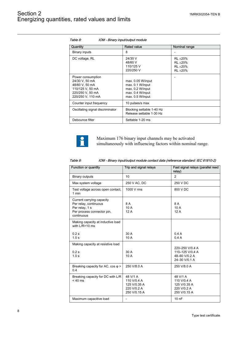
Table 8: IOM - Binary input/output module
Quantity Rated value Nominal rangeBinary inputs 8 -
DC voltage, RL 24/30 V48/60 V110/125 V220/250 V
RL ±20%RL ±20%RL ±20%RL ±20%
Power consumption24/30 V, 50 mA48/60 V, 50 mA110/125 V, 50 mA220/250 V, 50 mA220/250 V, 110 mA
max. 0.05 W/inputmax. 0.1 W/inputmax. 0.2 W/inputmax. 0.4 W/inputmax. 0.5 W/input
-
Counter input frequency 10 pulses/s max
Oscillating signal discriminator Blocking settable 1-40 HzRelease settable 1-30 Hz
Debounce filter Settable 1-20 ms
Maximum 176 binary input channels may be activatedsimultaneously with influencing factors within nominal range.
Table 9: IOM - Binary input/output module contact data (reference standard: IEC 61810-2)
Function or quantity Trip and signal relays Fast signal relays (parallel reedrelay)
Binary outputs 10 2
Max system voltage 250 V AC, DC 250 V DC
Test voltage across open contact,1 min
1000 V rms 800 V DC
Current carrying capacityPer relay, continuousPer relay, 1 sPer process connector pin,continuous
8 A10 A12 A
8 A10 A12 A
Making capacity at inductive loadwith L/R>10 ms 0.2 s1.0 s
30 A10 A
0.4 A0.4 A
Making capacity at resistive load 0.2 s1.0 s
30 A10 A
220–250 V/0.4 A110–125 V/0.4 A48–60 V/0.2 A24–30 V/0.1 A
Breaking capacity for AC, cos φ >0.4
250 V/8.0 A 250 V/8.0 A
Breaking capacity for DC with L/R< 40 ms
48 V/1 A110 V/0.4 A125 V/0.35 A220 V/0.2 A250 V/0.15 A
48 V/1 A110 V/0.4 A125 V/0.35 A220 V/0.2 A250 V/0.15 A
Maximum capacitive load - 10 nF
Section 2 1MRK502054-TEN BEnergizing quantities, rated values and limits
8Type test certificate
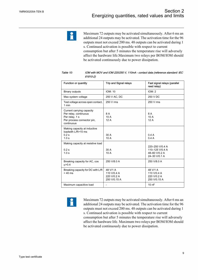
Maximum 72 outputs may be activated simultaneously. After 6 ms anadditional 24 outputs may be activated. The activation time for the 96outputs must not exceed 200 ms. 48 outputs can be activated during 1s. Continued activation is possible with respect to currentconsumption but after 5 minutes the temperature rise will adverselyaffect the hardware life.Maximum two relays per BOM/IOM shouldbe activated continuously due to power dissipation.
Table 10: IOM with MOV and IOM 220/250 V, 110mA - contact data (reference standard: IEC61810-2)
Function or quantity Trip and Signal relays Fast signal relays (parallelreed relay)
Binary outputs IOM: 10 IOM: 2
Max system voltage 250 V AC, DC 250 V DC
Test voltage across open contact,1 min
250 V rms 250 V rms
Current carrying capacityPer relay, continuousPer relay, 1 sPer process connector pin,continuous
8 A10 A12 A
8 A10 A12 A
Making capacity at inductiveloadwith L/R>10 ms0.2 s1.0 s
30 A10 A
0.4 A0.4 A
Making capacity at resistive load 0.2 s1.0 s
30 A10 A
220–250 V/0.4 A110–125 V/0.4 A48–60 V/0.2 A24–30 V/0.1 A
Breaking capacity for AC, cosj>0.4
250 V/8.0 A 250 V/8.0 A
Breaking capacity for DC with L/R< 40 ms
48 V/1 A110 V/0.4 A220 V/0.2 A250 V/0.15 A
48 V/1 A110 V/0.4 A220 V/0.2 A250 V/0.15 A
Maximum capacitive load - 10 nF
Maximum 72 outputs may be activated simultaneously. After 6 ms anadditional 24 outputs may be activated. The activation time for the 96outputs must not exceed 200 ms. 48 outputs can be activated during 1s. Continued activation is possible with respect to currentconsumption but after 5 minutes the temperature rise will adverselyaffect the hardware life. Maximum two relays per BOM/IOM shouldbe activated continuously due to power dissipation.
1MRK502054-TEN B Section 2Energizing quantities, rated values and limits
9Type test certificate
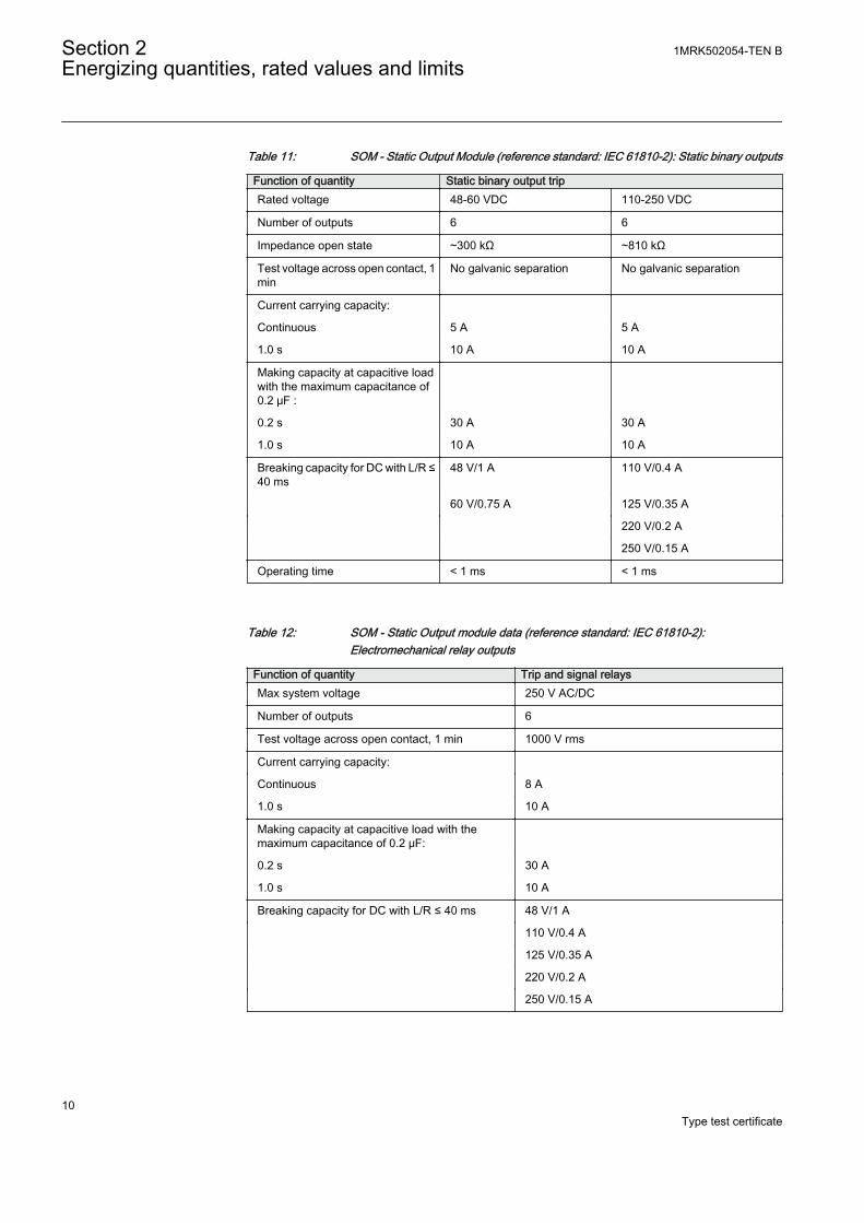
Table 11: SOM - Static Output Module (reference standard: IEC 61810-2): Static binary outputs
Function of quantity Static binary output tripRated voltage 48-60 VDC 110-250 VDC
Number of outputs 6 6
Impedance open state ~300 kΩ ~810 kΩ
Test voltage across open contact, 1min
No galvanic separation No galvanic separation
Current carrying capacity:
Continuous 5 A 5 A
1.0 s 10 A 10 A
Making capacity at capacitive loadwith the maximum capacitance of0.2 μF :
0.2 s 30 A 30 A
1.0 s 10 A 10 A
Breaking capacity for DC with L/R ≤40 ms
48 V/1 A 110 V/0.4 A
60 V/0.75 A 125 V/0.35 A
220 V/0.2 A
250 V/0.15 A
Operating time < 1 ms < 1 ms
Table 12: SOM - Static Output module data (reference standard: IEC 61810-2):Electromechanical relay outputs
Function of quantity Trip and signal relaysMax system voltage 250 V AC/DC
Number of outputs 6
Test voltage across open contact, 1 min 1000 V rms
Current carrying capacity:
Continuous 8 A
1.0 s 10 A
Making capacity at capacitive load with themaximum capacitance of 0.2 μF:
0.2 s 30 A
1.0 s 10 A
Breaking capacity for DC with L/R ≤ 40 ms 48 V/1 A
110 V/0.4 A
125 V/0.35 A
220 V/0.2 A
250 V/0.15 A
Section 2 1MRK502054-TEN BEnergizing quantities, rated values and limits
10Type test certificate
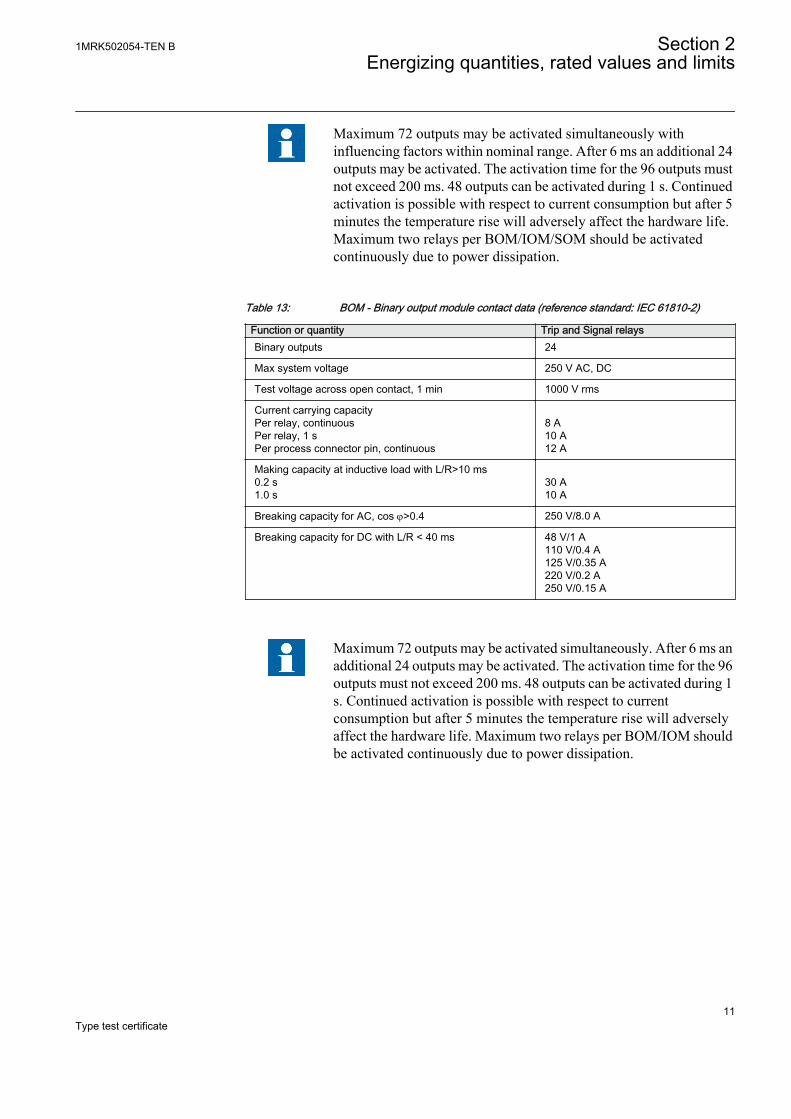
Maximum 72 outputs may be activated simultaneously withinfluencing factors within nominal range. After 6 ms an additional 24outputs may be activated. The activation time for the 96 outputs mustnot exceed 200 ms. 48 outputs can be activated during 1 s. Continuedactivation is possible with respect to current consumption but after 5minutes the temperature rise will adversely affect the hardware life.Maximum two relays per BOM/IOM/SOM should be activatedcontinuously due to power dissipation.
Table 13: BOM - Binary output module contact data (reference standard: IEC 61810-2)
Function or quantity Trip and Signal relaysBinary outputs 24
Max system voltage 250 V AC, DC
Test voltage across open contact, 1 min 1000 V rms
Current carrying capacityPer relay, continuousPer relay, 1 sPer process connector pin, continuous
8 A10 A12 A
Making capacity at inductive load with L/R>10 ms0.2 s1.0 s
30 A10 A
Breaking capacity for AC, cos j>0.4 250 V/8.0 A
Breaking capacity for DC with L/R < 40 ms 48 V/1 A110 V/0.4 A125 V/0.35 A220 V/0.2 A250 V/0.15 A
Maximum 72 outputs may be activated simultaneously. After 6 ms anadditional 24 outputs may be activated. The activation time for the 96outputs must not exceed 200 ms. 48 outputs can be activated during 1s. Continued activation is possible with respect to currentconsumption but after 5 minutes the temperature rise will adverselyaffect the hardware life. Maximum two relays per BOM/IOM shouldbe activated continuously due to power dissipation.
1MRK502054-TEN B Section 2Energizing quantities, rated values and limits
11Type test certificate
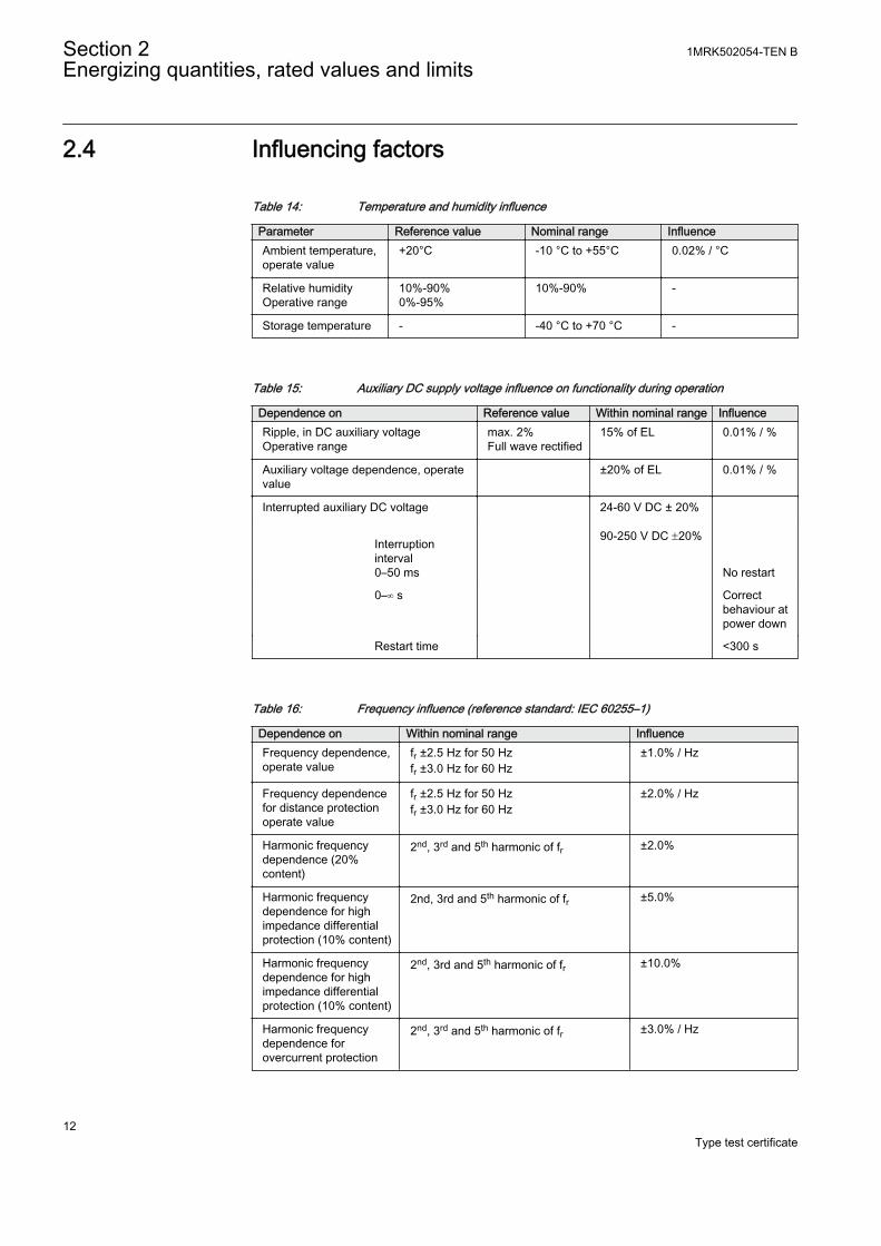
2.4 Influencing factors
Table 14: Temperature and humidity influence
Parameter Reference value Nominal range InfluenceAmbient temperature,operate value
+20°C -10 °C to +55°C 0.02% / °C
Relative humidityOperative range
10%-90%0%-95%
10%-90% -
Storage temperature - -40 °C to +70 °C -
Table 15: Auxiliary DC supply voltage influence on functionality during operation
Dependence on Reference value Within nominal range InfluenceRipple, in DC auxiliary voltageOperative range
max. 2%Full wave rectified
15% of EL 0.01% / %
Auxiliary voltage dependence, operatevalue
±20% of EL 0.01% / %
Interrupted auxiliary DC voltage
24-60 V DC ± 20% 90-250 V DC ±20%
Interruptioninterval0–50 ms
No restart
0–∞ s Correctbehaviour atpower down
Restart time <300 s
Table 16: Frequency influence (reference standard: IEC 60255–1)
Dependence on Within nominal range InfluenceFrequency dependence,operate value
fr ±2.5 Hz for 50 Hzfr ±3.0 Hz for 60 Hz
±1.0% / Hz
Frequency dependencefor distance protectionoperate value
fr ±2.5 Hz for 50 Hzfr ±3.0 Hz for 60 Hz
±2.0% / Hz
Harmonic frequencydependence (20%content)
2nd, 3rd and 5th harmonic of fr ±2.0%
Harmonic frequencydependence for highimpedance differentialprotection (10% content)
2nd, 3rd and 5th harmonic of fr ±5.0%
Harmonic frequencydependence for highimpedance differentialprotection (10% content)
2nd, 3rd and 5th harmonic of fr ±10.0%
Harmonic frequencydependence forovercurrent protection
2nd, 3rd and 5th harmonic of fr ±3.0% / Hz
Section 2 1MRK502054-TEN BEnergizing quantities, rated values and limits
12Type test certificate
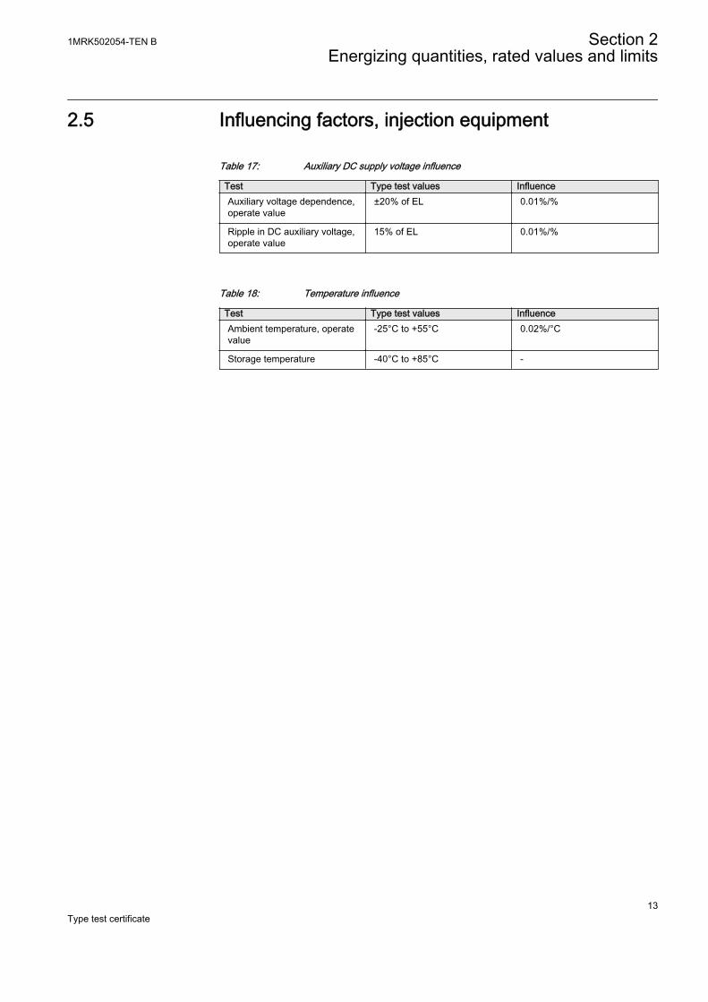
2.5 Influencing factors, injection equipment
Table 17: Auxiliary DC supply voltage influence
Test Type test values InfluenceAuxiliary voltage dependence,operate value
±20% of EL 0.01%/%
Ripple in DC auxiliary voltage,operate value
15% of EL 0.01%/%
Table 18: Temperature influence
Test Type test values InfluenceAmbient temperature, operatevalue
-25°C to +55°C 0.02%/°C
Storage temperature -40°C to +85°C -
1MRK502054-TEN B Section 2Energizing quantities, rated values and limits
13Type test certificate

14
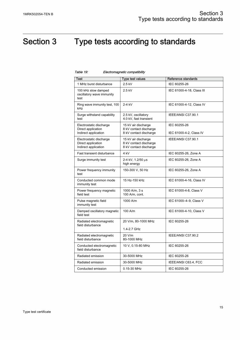
Section 3 Type tests according to standards
Table 19: Electromagnetic compatibility
Test Type test values Reference standards1 MHz burst disturbance 2.5 kV IEC 60255-26
100 kHz slow dampedoscillatory wave immunitytest
2.5 kV IEC 61000-4-18, Class III
Ring wave immunity test, 100kHz
2-4 kV IEC 61000-4-12, Class IV
Surge withstand capabilitytest
2.5 kV, oscillatory4.0 kV, fast transient
IEEE/ANSI C37.90.1
Electrostatic dischargeDirect applicationIndirect application
15 kV air discharge8 kV contact discharge8 kV contact discharge
IEC 60255-26 IEC 61000-4-2, Class IV
Electrostatic dischargeDirect applicationIndirect application
15 kV air discharge8 kV contact discharge8 kV contact discharge
IEEE/ANSI C37.90.1
Fast transient disturbance 4 kV IEC 60255-26, Zone A
Surge immunity test 2-4 kV, 1.2/50 mshigh energy
IEC 60255-26, Zone A
Power frequency immunitytest
150-300 V, 50 Hz IEC 60255-26, Zone A
Conducted common modeimmunity test
15 Hz-150 kHz IEC 61000-4-16, Class IV
Power frequency magneticfield test
1000 A/m, 3 s100 A/m, cont.
IEC 61000-4-8, Class V
Pulse magnetic fieldimmunity test
1000 A/m IEC 61000–4–9, Class V
Damped oscillatory magneticfield test
100 A/m IEC 61000-4-10, Class V
Radiated electromagneticfield disturbance
20 V/m, 80-1000 MHz 1.4-2.7 GHz
IEC 60255-26
Radiated electromagneticfield disturbance
20 V/m80-1000 MHz
IEEE/ANSI C37.90.2
Conducted electromagneticfield disturbance
10 V, 0.15-80 MHz IEC 60255-26
Radiated emission 30-5000 MHz IEC 60255-26
Radiated emission 30-5000 MHz IEEE/ANSI C63.4, FCC
Conducted emission 0.15-30 MHz IEC 60255-26
1MRK502054-TEN B Section 3Type tests according to standards
15Type test certificate
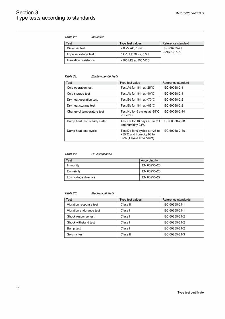
Table 20: Insulation
Test Type test values Reference standardDielectric test 2.0 kV AC, 1 min. IEC 60255-27
ANSI C37.90Impulse voltage test 5 kV, 1.2/50 ms, 0.5 J
Insulation resistance >100 MW at 500 VDC
Table 21: Environmental tests
Test Type test value Reference standardCold operation test Test Ad for 16 h at -25°C IEC 60068-2-1
Cold storage test Test Ab for 16 h at -40°C IEC 60068-2-1
Dry heat operation test Test Bd for 16 h at +70°C IEC 60068-2-2
Dry heat storage test Test Bb for 16 h at +85°C IEC 60068-2-2
Change of temperature test Test Nb for 5 cycles at -25°Cto +70°C
IEC 60068-2-14
Damp heat test, steady state Test Ca for 10 days at +40°Cand humidity 93%
IEC 60068-2-78
Damp heat test, cyclic Test Db for 6 cycles at +25 to+55°C and humidity 93 to95% (1 cycle = 24 hours)
IEC 60068-2-30
Table 22: CE compliance
Test According toImmunity EN 60255–26
Emissivity EN 60255–26
Low voltage directive EN 60255–27
Table 23: Mechanical tests
Test Type test values Reference standardsVibration response test Class II IEC 60255-21-1
Vibration endurance test Class I IEC 60255-21-1
Shock response test Class I IEC 60255-21-2
Shock withstand test Class I IEC 60255-21-2
Bump test Class I IEC 60255-21-2
Seismic test Class II IEC 60255-21-3
Section 3 1MRK502054-TEN BType tests according to standards
16Type test certificate
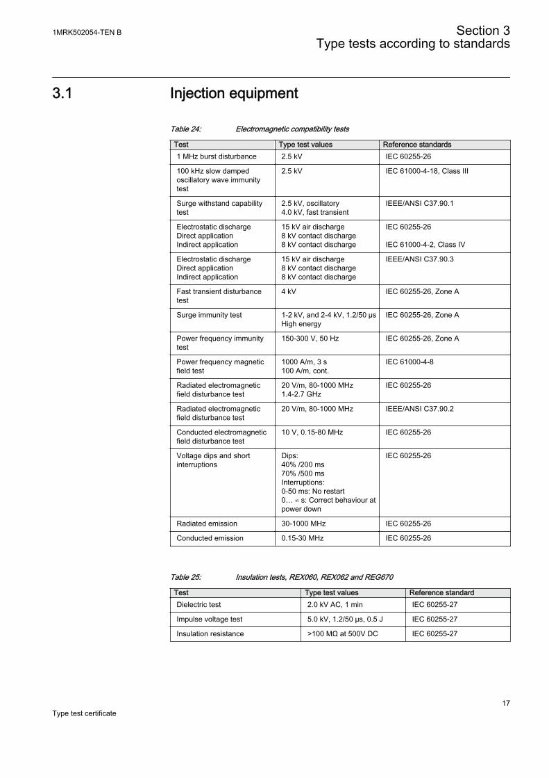
3.1 Injection equipment
Table 24: Electromagnetic compatibility tests
Test Type test values Reference standards1 MHz burst disturbance 2.5 kV IEC 60255-26
100 kHz slow dampedoscillatory wave immunitytest
2.5 kV IEC 61000-4-18, Class III
Surge withstand capabilitytest
2.5 kV, oscillatory4.0 kV, fast transient
IEEE/ANSI C37.90.1
Electrostatic dischargeDirect applicationIndirect application
15 kV air discharge8 kV contact discharge8 kV contact discharge
IEC 60255-26 IEC 61000-4-2, Class IV
Electrostatic dischargeDirect applicationIndirect application
15 kV air discharge8 kV contact discharge8 kV contact discharge
IEEE/ANSI C37.90.3
Fast transient disturbancetest
4 kV IEC 60255-26, Zone A
Surge immunity test 1-2 kV, and 2-4 kV, 1.2/50 µsHigh energy
IEC 60255-26, Zone A
Power frequency immunitytest
150-300 V, 50 Hz IEC 60255-26, Zone A
Power frequency magneticfield test
1000 A/m, 3 s100 A/m, cont.
IEC 61000-4-8
Radiated electromagneticfield disturbance test
20 V/m, 80-1000 MHz1.4-2.7 GHz
IEC 60255-26
Radiated electromagneticfield disturbance test
20 V/m, 80-1000 MHz IEEE/ANSI C37.90.2
Conducted electromagneticfield disturbance test
10 V, 0.15-80 MHz IEC 60255-26
Voltage dips and shortinterruptions
Dips:40% /200 ms70% /500 msInterruptions:0-50 ms: No restart0… ∞ s: Correct behaviour atpower down
IEC 60255-26
Radiated emission 30-1000 MHz IEC 60255-26
Conducted emission 0.15-30 MHz IEC 60255-26
Table 25: Insulation tests, REX060, REX062 and REG670
Test Type test values Reference standardDielectric test 2.0 kV AC, 1 min IEC 60255-27
Impulse voltage test 5.0 kV, 1.2/50 µs, 0.5 J IEC 60255-27
Insulation resistance >100 MΩ at 500V DC IEC 60255-27
1MRK502054-TEN B Section 3Type tests according to standards
17Type test certificate
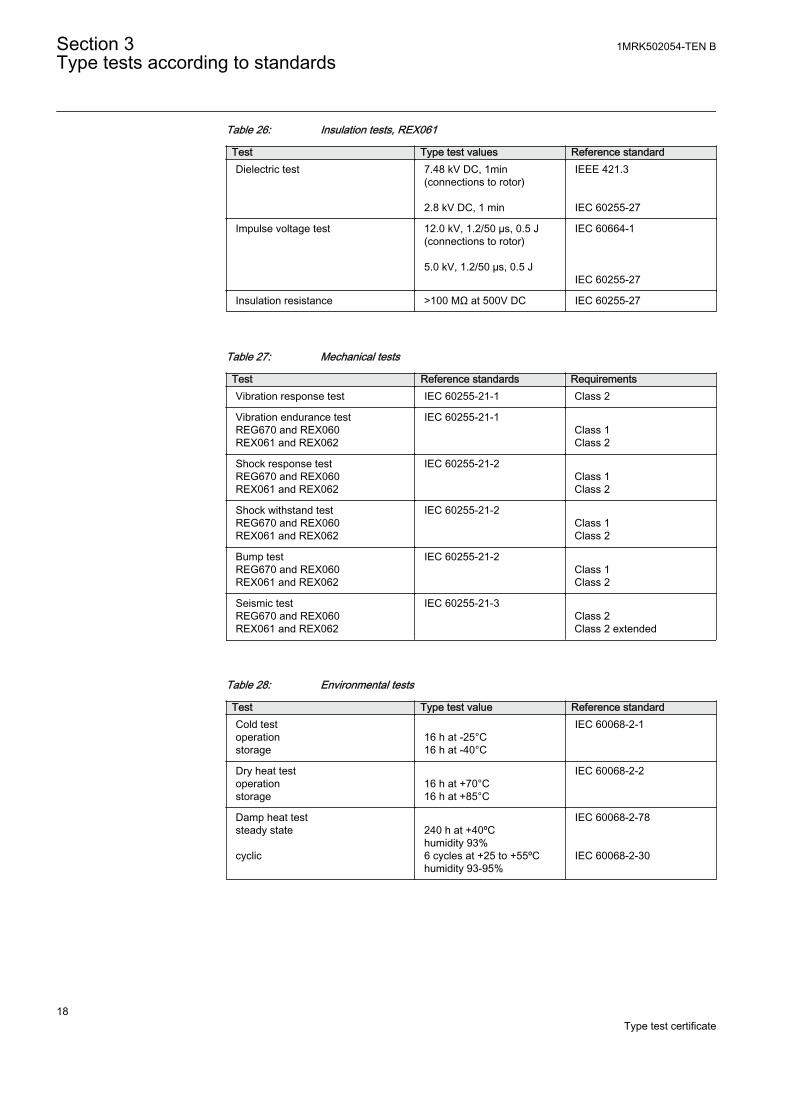
Table 26: Insulation tests, REX061
Test Type test values Reference standardDielectric test 7.48 kV DC, 1min
(connections to rotor) 2.8 kV DC, 1 min
IEEE 421.3 IEC 60255-27
Impulse voltage test 12.0 kV, 1.2/50 µs, 0.5 J(connections to rotor) 5.0 kV, 1.2/50 µs, 0.5 J
IEC 60664-1 IEC 60255-27
Insulation resistance >100 MΩ at 500V DC IEC 60255-27
Table 27: Mechanical tests
Test Reference standards RequirementsVibration response test IEC 60255-21-1 Class 2
Vibration endurance testREG670 and REX060REX061 and REX062
IEC 60255-21-1 Class 1Class 2
Shock response testREG670 and REX060REX061 and REX062
IEC 60255-21-2 Class 1Class 2
Shock withstand testREG670 and REX060REX061 and REX062
IEC 60255-21-2 Class 1Class 2
Bump testREG670 and REX060REX061 and REX062
IEC 60255-21-2 Class 1Class 2
Seismic testREG670 and REX060REX061 and REX062
IEC 60255-21-3 Class 2Class 2 extended
Table 28: Environmental tests
Test Type test value Reference standardCold testoperationstorage
16 h at -25°C16 h at -40°C
IEC 60068-2-1
Dry heat testoperationstorage
16 h at +70°C16 h at +85°C
IEC 60068-2-2
Damp heat teststeady state cyclic
240 h at +40ºChumidity 93%6 cycles at +25 to +55ºChumidity 93-95%
IEC 60068-2-78 IEC 60068-2-30
Section 3 1MRK502054-TEN BType tests according to standards
18Type test certificate
Section 4 Control
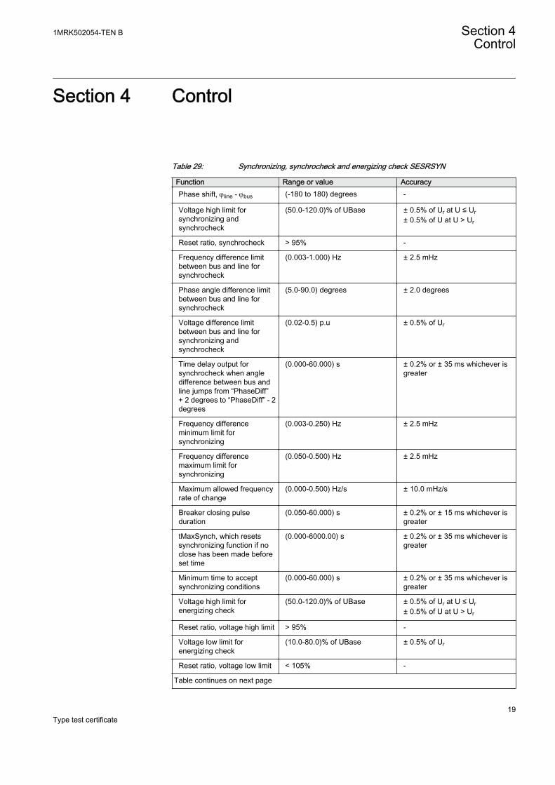
Table 29: Synchronizing, synchrocheck and energizing check SESRSYN
Function Range or value AccuracyPhase shift, jline - jbus (-180 to 180) degrees -
Voltage high limit forsynchronizing andsynchrocheck
(50.0-120.0)% of UBase ± 0.5% of Ur at U ≤ Ur± 0.5% of U at U > Ur
Reset ratio, synchrocheck > 95% -
Frequency difference limitbetween bus and line forsynchrocheck
(0.003-1.000) Hz ± 2.5 mHz
Phase angle difference limitbetween bus and line forsynchrocheck
(5.0-90.0) degrees ± 2.0 degrees
Voltage difference limitbetween bus and line forsynchronizing andsynchrocheck
(0.02-0.5) p.u ± 0.5% of Ur
Time delay output forsynchrocheck when angledifference between bus andline jumps from “PhaseDiff”+ 2 degrees to “PhaseDiff” - 2degrees
(0.000-60.000) s ± 0.2% or ± 35 ms whichever isgreater
Frequency differenceminimum limit forsynchronizing
(0.003-0.250) Hz ± 2.5 mHz
Frequency differencemaximum limit forsynchronizing
(0.050-0.500) Hz ± 2.5 mHz
Maximum allowed frequencyrate of change
(0.000-0.500) Hz/s ± 10.0 mHz/s
Breaker closing pulseduration
(0.050-60.000) s ± 0.2% or ± 15 ms whichever isgreater
tMaxSynch, which resetssynchronizing function if noclose has been made beforeset time
(0.000-6000.00) s ± 0.2% or ± 35 ms whichever isgreater
Minimum time to acceptsynchronizing conditions
(0.000-60.000) s ± 0.2% or ± 35 ms whichever isgreater
Voltage high limit forenergizing check
(50.0-120.0)% of UBase ± 0.5% of Ur at U ≤ Ur± 0.5% of U at U > Ur
Reset ratio, voltage high limit > 95% -
Voltage low limit forenergizing check
(10.0-80.0)% of UBase ± 0.5% of Ur
Reset ratio, voltage low limit < 105% -
Table continues on next page
1MRK502054-TEN B Section 4Control
19Type test certificate
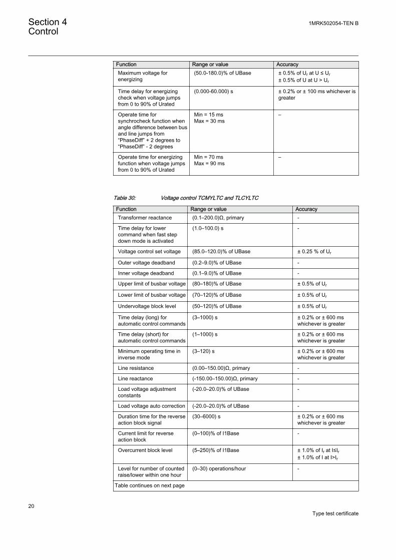
Function Range or value AccuracyMaximum voltage forenergizing
(50.0-180.0)% of UBase ± 0.5% of Ur at U ≤ Ur± 0.5% of U at U > Ur
Time delay for energizingcheck when voltage jumpsfrom 0 to 90% of Urated
(0.000-60.000) s ± 0.2% or ± 100 ms whichever isgreater
Operate time forsynchrocheck function whenangle difference between busand line jumps from“PhaseDiff” + 2 degrees to“PhaseDiff” - 2 degrees
Min = 15 msMax = 30 ms
–
Operate time for energizingfunction when voltage jumpsfrom 0 to 90% of Urated
Min = 70 msMax = 90 ms
–
Table 30: Voltage control TCMYLTC and TLCYLTC
Function Range or value AccuracyTransformer reactance (0.1–200.0)Ω, primary -
Time delay for lowercommand when fast stepdown mode is activated
(1.0–100.0) s -
Voltage control set voltage (85.0–120.0)% of UBase ± 0.25 % of Ur
Outer voltage deadband (0.2–9.0)% of UBase -
Inner voltage deadband (0.1–9.0)% of UBase -
Upper limit of busbar voltage (80–180)% of UBase ± 0.5% of Ur
Lower limit of busbar voltage (70–120)% of UBase ± 0.5% of Ur
Undervoltage block level (50–120)% of UBase ± 0.5% of Ur
Time delay (long) forautomatic control commands
(3–1000) s ± 0.2% or ± 600 mswhichever is greater
Time delay (short) forautomatic control commands
(1–1000) s ± 0.2% or ± 600 mswhichever is greater
Minimum operating time ininverse mode
(3–120) s ± 0.2% or ± 600 mswhichever is greater
Line resistance (0.00–150.00)Ω, primary -
Line reactance (-150.00–150.00)Ω, primary -
Load voltage adjustmentconstants
(-20.0–20.0)% of UBase -
Load voltage auto correction (-20.0–20.0)% of UBase -
Duration time for the reverseaction block signal
(30–6000) s ± 0.2% or ± 600 mswhichever is greater
Current limit for reverseaction block
(0–100)% of I1Base -
Overcurrent block level (5–250)% of I1Base ± 1.0% of Ir at I≤Ir± 1.0% of I at I>Ir
Level for number of countedraise/lower within one hour
(0–30) operations/hour -
Table continues on next page
Section 4 1MRK502054-TEN BControl
20Type test certificate
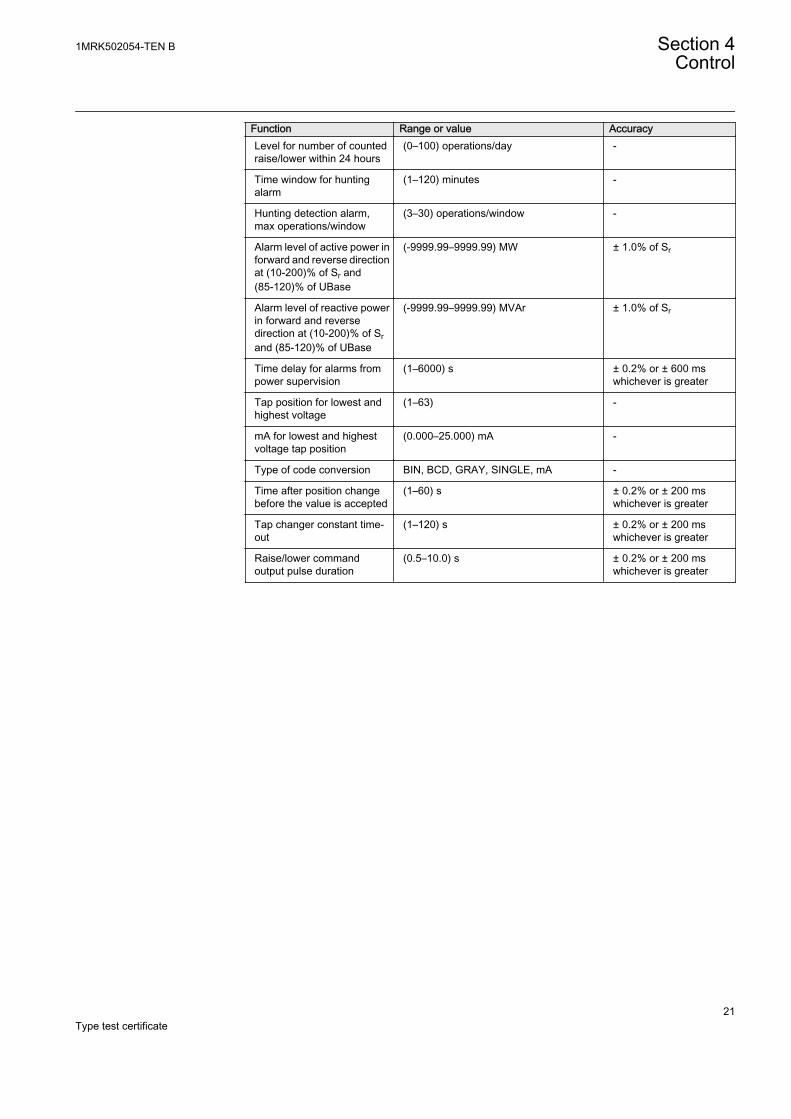
Function Range or value AccuracyLevel for number of countedraise/lower within 24 hours
(0–100) operations/day -
Time window for huntingalarm
(1–120) minutes -
Hunting detection alarm,max operations/window
(3–30) operations/window -
Alarm level of active power inforward and reverse directionat (10-200)% of Sr and(85-120)% of UBase
(-9999.99–9999.99) MW ± 1.0% of Sr
Alarm level of reactive powerin forward and reversedirection at (10-200)% of Srand (85-120)% of UBase
(-9999.99–9999.99) MVAr ± 1.0% of Sr
Time delay for alarms frompower supervision
(1–6000) s ± 0.2% or ± 600 mswhichever is greater
Tap position for lowest andhighest voltage
(1–63) -
mA for lowest and highestvoltage tap position
(0.000–25.000) mA -
Type of code conversion BIN, BCD, GRAY, SINGLE, mA -
Time after position changebefore the value is accepted
(1–60) s ± 0.2% or ± 200 mswhichever is greater
Tap changer constant time-out
(1–120) s ± 0.2% or ± 200 mswhichever is greater
Raise/lower commandoutput pulse duration
(0.5–10.0) s ± 0.2% or ± 200 mswhichever is greater
1MRK502054-TEN B Section 4Control
21Type test certificate

22
Section 5 Differential protection
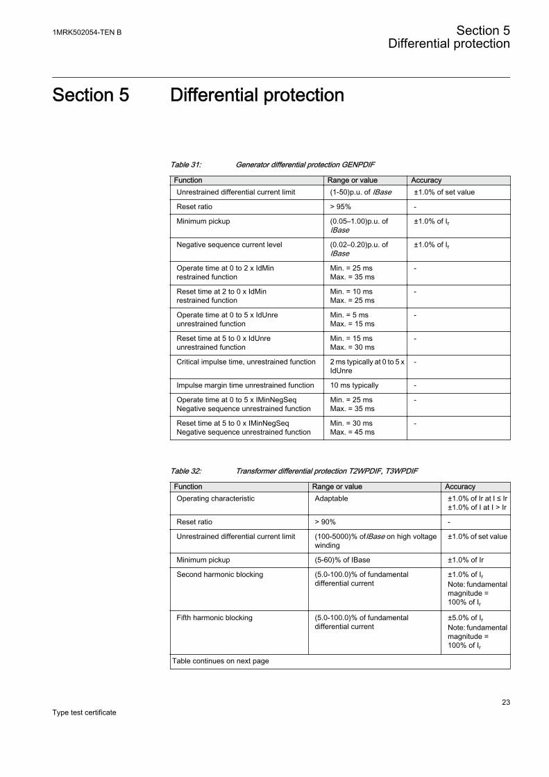
Table 31: Generator differential protection GENPDIF
Function Range or value AccuracyUnrestrained differential current limit (1-50)p.u. of IBase ±1.0% of set value
Reset ratio > 95% -
Minimum pickup (0.05–1.00)p.u. ofIBase
±1.0% of Ir
Negative sequence current level (0.02–0.20)p.u. ofIBase
±1.0% of Ir
Operate time at 0 to 2 x IdMinrestrained function
Min. = 25 msMax. = 35 ms
-
Reset time at 2 to 0 x IdMinrestrained function
Min. = 10 msMax. = 25 ms
-
Operate time at 0 to 5 x IdUnreunrestrained function
Min. = 5 msMax. = 15 ms
-
Reset time at 5 to 0 x IdUnreunrestrained function
Min. = 15 msMax. = 30 ms
-
Critical impulse time, unrestrained function 2 ms typically at 0 to 5 xIdUnre
-
Impulse margin time unrestrained function 10 ms typically -
Operate time at 0 to 5 x IMinNegSeqNegative sequence unrestrained function
Min. = 25 msMax. = 35 ms
-
Reset time at 5 to 0 x IMinNegSeqNegative sequence unrestrained function
Min. = 30 msMax. = 45 ms
-
Table 32: Transformer differential protection T2WPDIF, T3WPDIF
Function Range or value AccuracyOperating characteristic Adaptable ±1.0% of Ir at I ≤ Ir
±1.0% of I at I > Ir
Reset ratio > 90% -
Unrestrained differential current limit (100-5000)% ofIBase on high voltagewinding
±1.0% of set value
Minimum pickup (5-60)% of IBase ±1.0% of Ir
Second harmonic blocking (5.0-100.0)% of fundamentaldifferential current
±1.0% of IrNote: fundamentalmagnitude =100% of Ir
Fifth harmonic blocking (5.0-100.0)% of fundamentaldifferential current
±5.0% of IrNote: fundamentalmagnitude =100% of Ir
Table continues on next page
1MRK502054-TEN B Section 5Differential protection
23Type test certificate
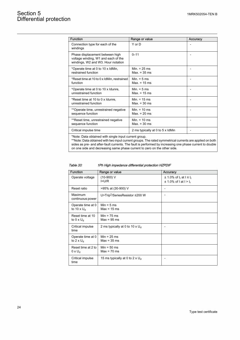
Function Range or value AccuracyConnection type for each of thewindings
Y or D -
Phase displacement between highvoltage winding, W1 and each of thewindings, W2 and W3. Hour notation
0–11 -
*Operate time at 0 to 10 x IdMin,restrained function
Min. = 25 msMax. = 35 ms
-
*Reset time at 10 to 0 x IdMin, restrainedfunction
Min. = 5 msMax. = 15 ms
-
*Operate time at 0 to 10 x Idunre,unrestrained function
Min. = 5 msMax. = 15 ms
-
*Reset time at 10 to 0 x Idunre,unrestrained function
Min. = 15 msMax. = 30 ms
-
**Operate time, unrestrained negativesequence function
Min. = 10 msMax. = 20 ms
-
**Reset time, unrestrained negativesequence function
Min. = 10 msMax. = 30 ms
-
Critical impulse time 2 ms typically at 0 to 5 x IdMin -
*Note: Data obtained with single input current group.**Note: Data obtained with two input current groups. The rated symmetrical currents are applied on bothsides as pre- and after-fault currents. The fault is performed by increasing one phase current to doubleon one side and decreasing same phase current to zero on the other side.
Table 33: 1Ph High impedance differential protection HZPDIF
Function Range or value AccuracyOperate voltage (10-900) V
I=U/R± 1.0% of Ir at I ≤ Ir± 1.0% of I at I > Ir
Reset ratio >95% at (30-900) V -
Maximumcontinuous power
U>Trip2/SeriesResistor ≤200 W -
Operate time at 0to 10 x Ud
Min = 5 msMax = 15 ms
Reset time at 10to 0 x Ud
Min = 75 msMax = 95 ms
Critical impulsetime
2 ms typically at 0 to 10 x Ud -
Operate time at 0to 2 x Ud
Min = 25 msMax = 35 ms
Reset time at 2 to0 x Ud
Min = 50 msMax = 70 ms
Critical impulsetime
15 ms typically at 0 to 2 x Ud -
Section 5 1MRK502054-TEN BDifferential protection
24Type test certificate
Section 6 Impedance protection
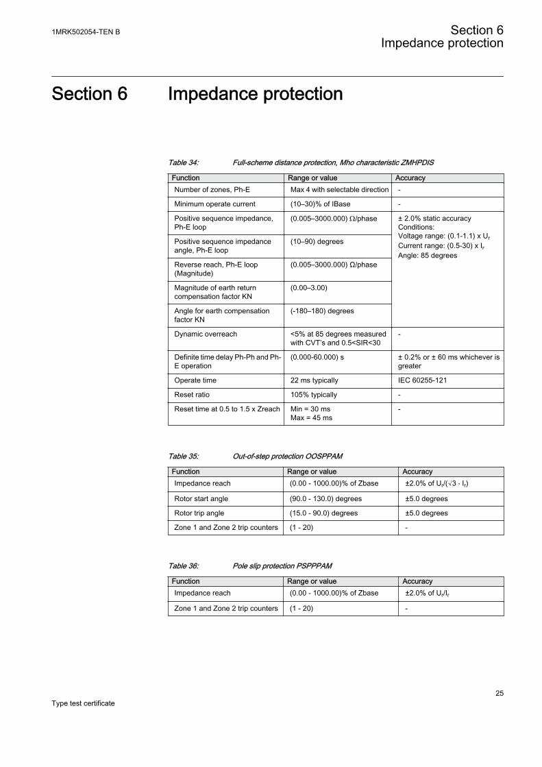
Table 34: Full-scheme distance protection, Mho characteristic ZMHPDIS
Function Range or value AccuracyNumber of zones, Ph-E Max 4 with selectable direction -
Minimum operate current (10–30)% of IBase -
Positive sequence impedance,Ph-E loop
(0.005–3000.000) W/phase ± 2.0% static accuracyConditions:Voltage range: (0.1-1.1) x UrCurrent range: (0.5-30) x IrAngle: 85 degrees
Positive sequence impedanceangle, Ph-E loop
(10–90) degrees
Reverse reach, Ph-E loop(Magnitude)
(0.005–3000.000) Ω/phase
Magnitude of earth returncompensation factor KN
(0.00–3.00)
Angle for earth compensationfactor KN
(-180–180) degrees
Dynamic overreach <5% at 85 degrees measuredwith CVT’s and 0.5<SIR<30
-
Definite time delay Ph-Ph and Ph-E operation
(0.000-60.000) s ± 0.2% or ± 60 ms whichever isgreater
Operate time 22 ms typically IEC 60255-121
Reset ratio 105% typically -
Reset time at 0.5 to 1.5 x Zreach Min = 30 msMax = 45 ms
-
Table 35: Out-of-step protection OOSPPAM
Function Range or value AccuracyImpedance reach (0.00 - 1000.00)% of Zbase ±2.0% of Ur/(√3 ⋅ Ir)
Rotor start angle (90.0 - 130.0) degrees ±5.0 degrees
Rotor trip angle (15.0 - 90.0) degrees ±5.0 degrees
Zone 1 and Zone 2 trip counters (1 - 20) -
Table 36: Pole slip protection PSPPPAM
Function Range or value AccuracyImpedance reach (0.00 - 1000.00)% of Zbase ±2.0% of Ur/Ir
Zone 1 and Zone 2 trip counters (1 - 20) -
1MRK502054-TEN B Section 6Impedance protection
25Type test certificate
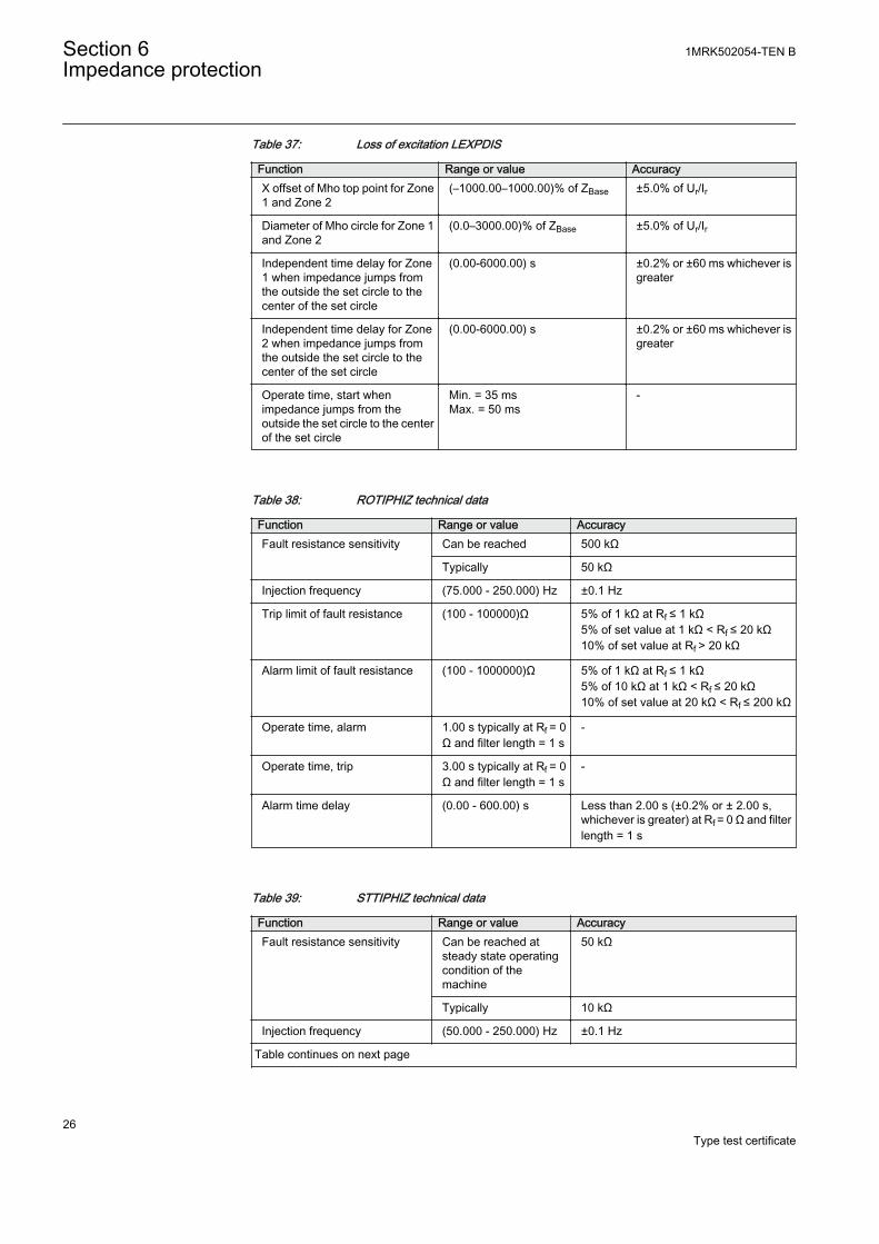
Table 37: Loss of excitation LEXPDIS
Function Range or value AccuracyX offset of Mho top point for Zone1 and Zone 2
(–1000.00–1000.00)% of ZBase ±5.0% of Ur/Ir
Diameter of Mho circle for Zone 1and Zone 2
(0.0–3000.00)% of ZBase ±5.0% of Ur/Ir
Independent time delay for Zone1 when impedance jumps fromthe outside the set circle to thecenter of the set circle
(0.00-6000.00) s ±0.2% or ±60 ms whichever isgreater
Independent time delay for Zone2 when impedance jumps fromthe outside the set circle to thecenter of the set circle
(0.00-6000.00) s ±0.2% or ±60 ms whichever isgreater
Operate time, start whenimpedance jumps from theoutside the set circle to the centerof the set circle
Min. = 35 msMax. = 50 ms
-
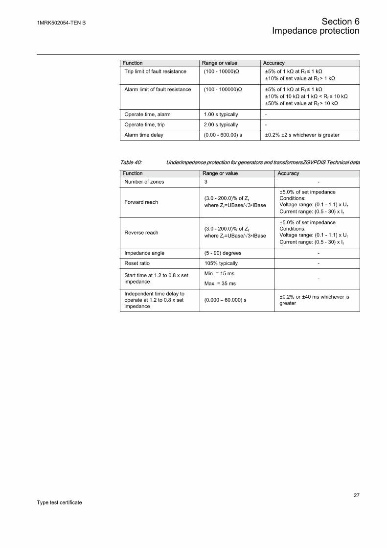
Table 38: ROTIPHIZ technical data
Function Range or value AccuracyFault resistance sensitivity Can be reached 500 kΩ
Typically 50 kΩ
Injection frequency (75.000 - 250.000) Hz ±0.1 Hz
Trip limit of fault resistance (100 - 100000)Ω 5% of 1 kΩ at Rf ≤ 1 kΩ5% of set value at 1 kΩ < Rf ≤ 20 kΩ10% of set value at Rf > 20 kΩ
Alarm limit of fault resistance (100 - 1000000)Ω 5% of 1 kΩ at Rf ≤ 1 kΩ5% of 10 kΩ at 1 kΩ < Rf ≤ 20 kΩ10% of set value at 20 kΩ < Rf ≤ 200 kΩ
Operate time, alarm 1.00 s typically at Rf = 0Ω and filter length = 1 s
-
Operate time, trip 3.00 s typically at Rf = 0Ω and filter length = 1 s
-
Alarm time delay (0.00 - 600.00) s Less than 2.00 s (±0.2% or ± 2.00 s,whichever is greater) at Rf = 0 Ω and filterlength = 1 s
Table 39: STTIPHIZ technical data
Function Range or value AccuracyFault resistance sensitivity Can be reached at
steady state operatingcondition of themachine
50 kΩ
Typically 10 kΩ
Injection frequency (50.000 - 250.000) Hz ±0.1 Hz
Table continues on next page
Section 6 1MRK502054-TEN BImpedance protection
26Type test certificate
Function Range or value AccuracyTrip limit of fault resistance (100 - 10000)Ω ±5% of 1 kΩ at Rf ≤ 1 kΩ
±10% of set value at Rf > 1 kΩ
Alarm limit of fault resistance (100 - 100000)Ω ±5% of 1 kΩ at Rf ≤ 1 kΩ±10% of 10 kΩ at 1 kΩ < Rf ≤ 10 kΩ±50% of set value at Rf > 10 kΩ
Operate time, alarm 1.00 s typically -
Operate time, trip 2.00 s typically -
Alarm time delay (0.00 - 600.00) s ±0.2% ±2 s whichever is greater
Table 40: Underimpedance protection for generators and transformersZGVPDIS Technical data
Function Range or value AccuracyNumber of zones 3 -
Forward reach(3.0 - 200.0)% of Zrwhere Zr=UBase/√3∗IBase
±5.0% of set impedanceConditions:Voltage range: (0.1 - 1.1) x UrCurrent range: (0.5 - 30) x Ir
Reverse reach(3.0 - 200.0)% of Zrwhere Zr=UBase/√3∗IBase
±5.0% of set impedanceConditions:Voltage range: (0.1 - 1.1) x UrCurrent range: (0.5 - 30) x Ir
Impedance angle (5 - 90) degrees -
Reset ratio 105% typically -
Start time at 1.2 to 0.8 x setimpedance
Min. = 15 ms-
Max. = 35 ms
Independent time delay tooperate at 1.2 to 0.8 x setimpedance
(0.000 – 60.000) s ±0.2% or ±40 ms whichever isgreater
1MRK502054-TEN B Section 6Impedance protection
27Type test certificate

28
Section 7 Current protection
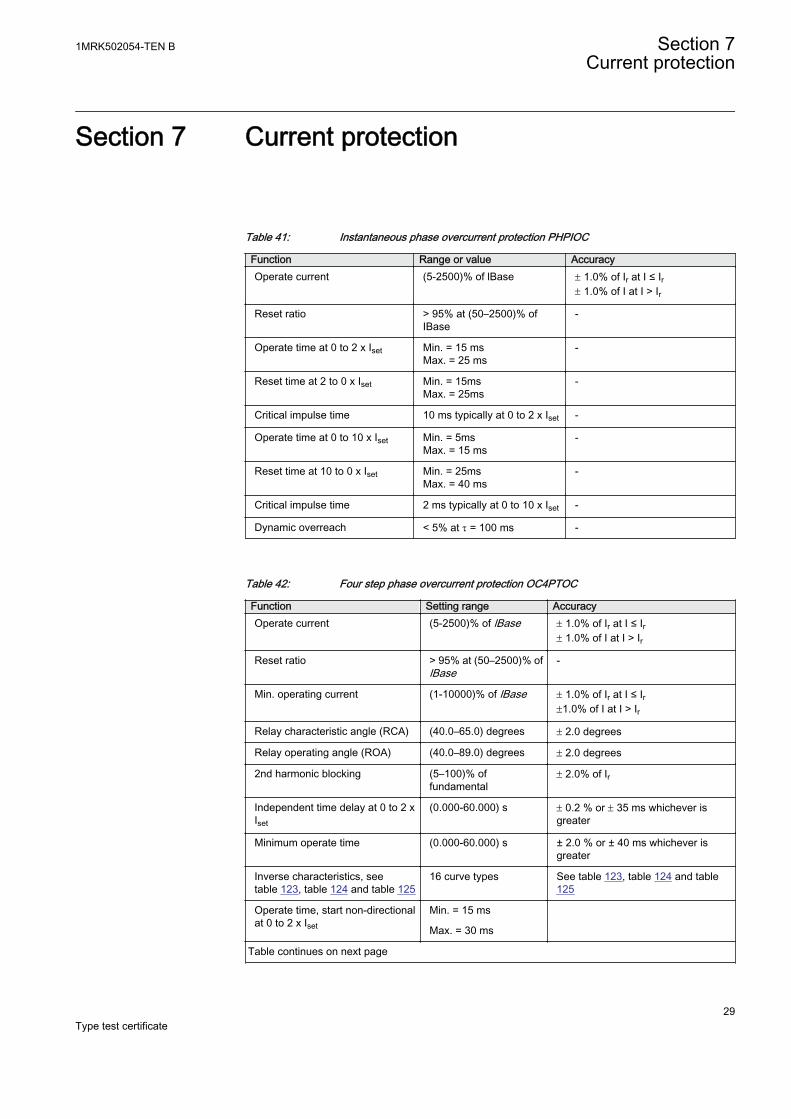
Table 41: Instantaneous phase overcurrent protection PHPIOC
Function Range or value AccuracyOperate current (5-2500)% of lBase ± 1.0% of Ir at I ≤ Ir
± 1.0% of I at I > Ir
Reset ratio > 95% at (50–2500)% ofIBase
-
Operate time at 0 to 2 x Iset Min. = 15 msMax. = 25 ms
-
Reset time at 2 to 0 x Iset Min. = 15msMax. = 25ms
-
Critical impulse time 10 ms typically at 0 to 2 x Iset -
Operate time at 0 to 10 x Iset Min. = 5msMax. = 15 ms
-
Reset time at 10 to 0 x Iset Min. = 25msMax. = 40 ms
-
Critical impulse time 2 ms typically at 0 to 10 x Iset -
Dynamic overreach < 5% at t = 100 ms -
Table 42: Four step phase overcurrent protection OC4PTOC
Function Setting range AccuracyOperate current (5-2500)% of lBase ± 1.0% of Ir at I ≤ Ir
± 1.0% of I at I > Ir
Reset ratio > 95% at (50–2500)% oflBase
-
Min. operating current (1-10000)% of lBase ± 1.0% of Ir at I ≤ Ir±1.0% of I at I > Ir
Relay characteristic angle (RCA) (40.0–65.0) degrees ± 2.0 degrees
Relay operating angle (ROA) (40.0–89.0) degrees ± 2.0 degrees
2nd harmonic blocking (5–100)% offundamental
± 2.0% of Ir
Independent time delay at 0 to 2 xIset
(0.000-60.000) s ± 0.2 % or ± 35 ms whichever isgreater
Minimum operate time (0.000-60.000) s ± 2.0 % or ± 40 ms whichever isgreater
Inverse characteristics, seetable 123, table 124 and table 125
16 curve types See table 123, table 124 and table125
Operate time, start non-directionalat 0 to 2 x Iset
Min. = 15 ms
Max. = 30 ms
Table continues on next page
1MRK502054-TEN B Section 7Current protection
29Type test certificate
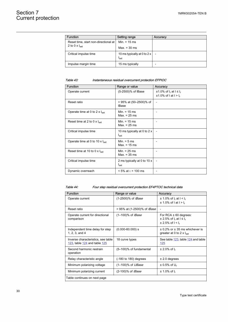
Function Setting range AccuracyReset time, start non-directional at2 to 0 x Iset
Min. = 15 ms
Max. = 30 ms
Critical impulse time 10 ms typically at 0 to 2 xIset
-
Impulse margin time 15 ms typically -
Table 43: Instantaneous residual overcurrent protection EFPIOC
Function Range or value AccuracyOperate current (5-2500)% of lBase ±1.0% of Ir at I ≤ Ir
±1.0% of I at I > Ir
Reset ratio > 95% at (50–2500)% oflBase
-
Operate time at 0 to 2 x Iset Min. = 15 msMax. = 25 ms
-
Reset time at 2 to 0 x Iset Min. = 15 msMax. = 25 ms
-
Critical impulse time 10 ms typically at 0 to 2 xIset
-
Operate time at 0 to 10 x Iset Min. = 5 msMax. = 15 ms
-
Reset time at 10 to 0 x Iset Min. = 25 msMax. = 35 ms
-
Critical impulse time 2 ms typically at 0 to 10 xIset
-
Dynamic overreach < 5% at t = 100 ms -
Table 44: Four step residual overcurrent protection EF4PTOC technical data
Function Range or value AccuracyOperate current (1-2500)% of lBase ± 1.0% of Ir at I < Ir
± 1.0% of I at I > Ir
Reset ratio > 95% at (1-2500)% of lBase -
Operate current for directionalcomparison
(1–100)% of lBase For RCA ± 60 degrees:± 2.5% of Ir at I ≤ Ir± 2.5% of I < Ir
Independent time delay for step1, 2, 3, and 4
(0.000-60.000) s ± 0.2% or ± 35 ms whichever isgreater at 0 to 2 x Iset
Inverse characteristics, see table123, table 124 and table 125
18 curve types See table 123, table 124 and table125
Second harmonic restrainoperation
(5–100)% of fundamental ± 2.0% of Ir
Relay characteristic angle (-180 to 180) degrees ± 2.0 degrees
Minimum polarizing voltage (1–100)% of UBase ± 0.5% of Ur
Minimum polarizing current (2-100)% of IBase ± 1.0% of Ir
Table continues on next page
Section 7 1MRK502054-TEN BCurrent protection
30Type test certificate
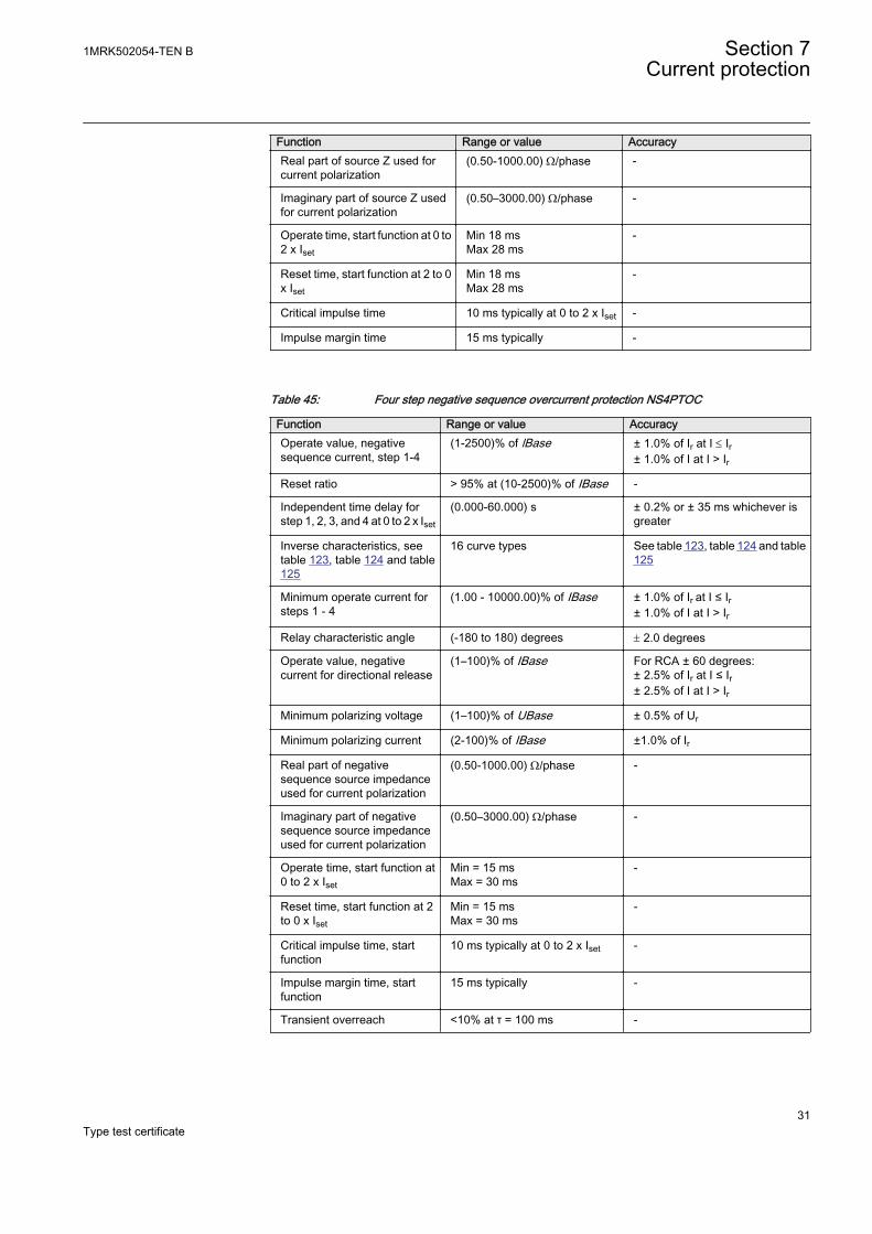
Function Range or value AccuracyReal part of source Z used forcurrent polarization
(0.50-1000.00) W/phase -
Imaginary part of source Z usedfor current polarization
(0.50–3000.00) W/phase -
Operate time, start function at 0 to2 x Iset
Min 18 msMax 28 ms
-
Reset time, start function at 2 to 0x Iset
Min 18 msMax 28 ms
-
Critical impulse time 10 ms typically at 0 to 2 x Iset -
Impulse margin time 15 ms typically -
Table 45: Four step negative sequence overcurrent protection NS4PTOC
Function Range or value AccuracyOperate value, negativesequence current, step 1-4
(1-2500)% of lBase ± 1.0% of Ir at I £ Ir± 1.0% of I at I > Ir
Reset ratio > 95% at (10-2500)% of IBase -
Independent time delay forstep 1, 2, 3, and 4 at 0 to 2 x Iset
(0.000-60.000) s ± 0.2% or ± 35 ms whichever isgreater
Inverse characteristics, seetable 123, table 124 and table125
16 curve types See table 123, table 124 and table125
Minimum operate current forsteps 1 - 4
(1.00 - 10000.00)% of IBase ± 1.0% of Ir at I ≤ Ir± 1.0% of I at I > Ir
Relay characteristic angle (-180 to 180) degrees ± 2.0 degrees
Operate value, negativecurrent for directional release
(1–100)% of IBase For RCA ± 60 degrees:± 2.5% of Ir at I ≤ Ir± 2.5% of I at I > Ir
Minimum polarizing voltage (1–100)% of UBase ± 0.5% of Ur
Minimum polarizing current (2-100)% of IBase ±1.0% of Ir
Real part of negativesequence source impedanceused for current polarization
(0.50-1000.00) W/phase -
Imaginary part of negativesequence source impedanceused for current polarization
(0.50–3000.00) W/phase -
Operate time, start function at0 to 2 x Iset
Min = 15 msMax = 30 ms
-
Reset time, start function at 2to 0 x Iset
Min = 15 msMax = 30 ms
-
Critical impulse time, startfunction
10 ms typically at 0 to 2 x Iset -
Impulse margin time, startfunction
15 ms typically -
Transient overreach <10% at τ = 100 ms -
1MRK502054-TEN B Section 7Current protection
31Type test certificate
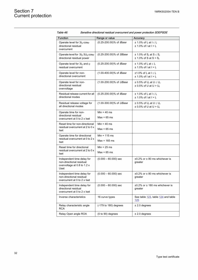
Table 46: Sensitive directional residual overcurrent and power protection SDEPSDE
Function Range or value AccuracyOperate level for 3I0·cosjdirectional residualovercurrent
(0.25-200.00)% of lBase ± 1.0% of Ir at I £ Ir± 1.0% of I at I > Ir
Operate level for ·3I0·3U0 cosjdirectional residual power
(0.25-200.00)% of SBase ± 1.0% of Sr at S £ Sr± 1.0% of S at S > Sr
Operate level for 3I0 and jresidual overcurrent
(0.25-200.00)% of lBase ± 1.0% of Ir at £ Ir± 1.0% of I at I > Ir
Operate level for non-directional overcurrent
(1.00-400.00)% of lBase ±1.0% of Ir at I £ Ir± 1.0% of I at I > Ir
Operate level for non-directional residualovervoltage
(1.00-200.00)% of UBase ± 0.5% of Ur at U £ Ur± 0.5% of U at U > Ur
Residual release current for alldirectional modes
(0.25-200.00)% of lBase ± 1.0% of Ir at I £ Ir± 1.0% of I at I > Ir
Residual release voltage forall directional modes
(1.00-300.00)% of UBase ± 0.5% of Ur at U £ Ur± 0.5% of U at U > Ur
Operate time for non-directional residualovercurrent at 0 to 2 x Iset
Min = 40 ms
Max = 65 ms
Reset time for non-directionalresidual overcurrent at 2 to 0 xIset
Min = 40 ms
Max = 65 ms
Operate time for directionalresidual overcurrent at 0 to 2 xIset
Min = 115 ms
Max = 165 ms
Reset time for directionalresidual overcurrent at 2 to 0 xIset
Min = 25 ms
Max = 65 ms
Independent time delay fornon-directional residualovervoltage at 0.8 to 1.2 xUset
(0.000 – 60.000) sec ±0.2% or ± 80 ms whichever isgreater
Independent time delay fornon-directional residualovercurrent at 0 to 2 x Iset
(0.000 – 60.000) sec ±0.2% or ± 80 ms whichever isgreater
Independent time delay fordirectional residualovercurrent at 0 to 2 x Iset
(0.000 – 60.000) sec ±0.2% or ± 180 ms whichever isgreater
Inverse characteristics 16 curve types See table 123, table 124 and table125
Relay characteristic angleRCA
(-179 to 180) degrees ± 2.0 degrees
Relay Open angle ROA (0 to 90) degrees ± 2.0 degrees
Section 7 1MRK502054-TEN BCurrent protection
32Type test certificate
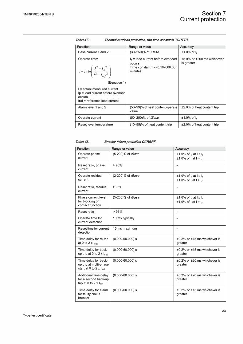
Table 47: Thermal overload protection, two time constants TRPTTR
Function Range or value AccuracyBase current 1 and 2 (30–250)% of IBase ±1.0% of Ir
Operate time:
2 2
2 2p
ref
I It ln
I It
æ ö-ç ÷= ×ç ÷-è ø
EQUATION1356 V2 EN (Equation 1)
I = actual measured currentIp = load current before overloadoccursIref = reference load current
Ip = load current before overloadoccursTime constant τ = (0.10–500.00)minutes
±5.0% or ±200 ms whicheveris greater
Alarm level 1 and 2 (50–99)% of heat content operatevalue
±2.0% of heat content trip
Operate current (50–250)% of IBase ±1.0% of Ir
Reset level temperature (10–95)% of heat content trip ±2.0% of heat content trip
Table 48: Breaker failure protection CCRBRF
Function Range or value AccuracyOperate phasecurrent
(5-200)% of lBase ±1.0% of Ir at I £ Ir±1.0% of I at I > Ir
Reset ratio, phasecurrent
> 95% -
Operate residualcurrent
(2-200)% of lBase ±1.0% of Ir at I £ Ir±1.0% of I at I > Ir
Reset ratio, residualcurrent
> 95% -
Phase current levelfor blocking ofcontact function
(5-200)% of lBase ±1.0% of Ir at I £ Ir±1.0% of I at I > Ir
Reset ratio > 95% -
Operate time forcurrent detection
10 ms typically -
Reset time for currentdetection
15 ms maximum -
Time delay for re-tripat 0 to 2 x Iset
(0.000-60.000) s ±0.2% or ±15 ms whichever isgreater
Time delay for back-up trip at 0 to 2 x Iset
(0.000-60.000) s ±0.2% or ±15 ms whichever isgreater
Time delay for back-up trip at multi-phasestart at 0 to 2 x Iset
(0.000-60.000) s ±0.2% or ±20 ms whichever isgreater
Additional time delayfor a second back-uptrip at 0 to 2 x Iset
(0.000-60.000) s ±0.2% or ±20 ms whichever isgreater
Time delay for alarmfor faulty circuitbreaker
(0.000-60.000) s ±0.2% or ±15 ms whichever isgreater
1MRK502054-TEN B Section 7Current protection
33Type test certificate
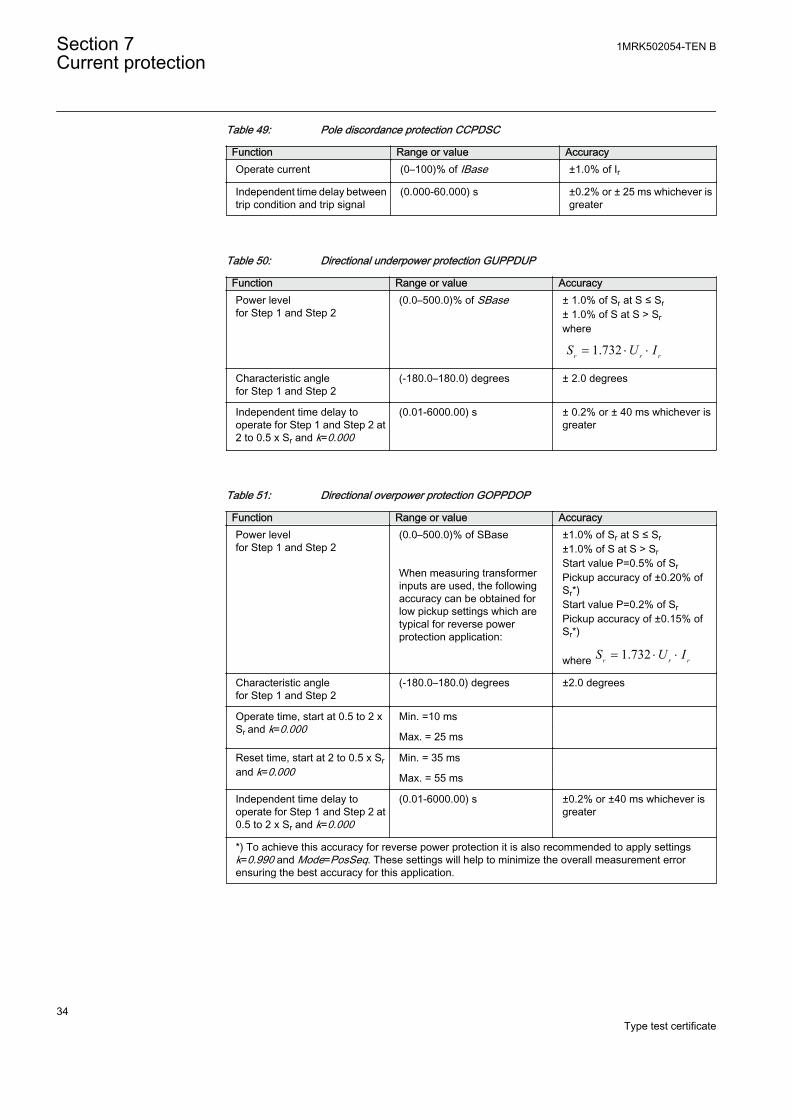
Table 49: Pole discordance protection CCPDSC
Function Range or value AccuracyOperate current (0–100)% of IBase ±1.0% of Ir
Independent time delay betweentrip condition and trip signal
(0.000-60.000) s ±0.2% or ± 25 ms whichever isgreater
Table 50: Directional underpower protection GUPPDUP
Function Range or value AccuracyPower levelfor Step 1 and Step 2
(0.0–500.0)% of SBase ± 1.0% of Sr at S ≤ Sr± 1.0% of S at S > Srwhere
1.732r r rS U I= × ×
Characteristic anglefor Step 1 and Step 2
(-180.0–180.0) degrees ± 2.0 degrees
Independent time delay tooperate for Step 1 and Step 2 at2 to 0.5 x Sr and k=0.000
(0.01-6000.00) s ± 0.2% or ± 40 ms whichever isgreater
Table 51: Directional overpower protection GOPPDOP
Function Range or value AccuracyPower levelfor Step 1 and Step 2
(0.0–500.0)% of SBase When measuring transformerinputs are used, the followingaccuracy can be obtained forlow pickup settings which aretypical for reverse powerprotection application:
±1.0% of Sr at S ≤ Sr±1.0% of S at S > SrStart value P=0.5% of SrPickup accuracy of ±0.20% ofSr*)Start value P=0.2% of SrPickup accuracy of ±0.15% ofSr*)
where 1.732r r rS U I= × ×
Characteristic anglefor Step 1 and Step 2
(-180.0–180.0) degrees ±2.0 degrees
Operate time, start at 0.5 to 2 xSr and k=0.000
Min. =10 ms
Max. = 25 ms
Reset time, start at 2 to 0.5 x Srand k=0.000
Min. = 35 ms
Max. = 55 ms
Independent time delay tooperate for Step 1 and Step 2 at0.5 to 2 x Sr and k=0.000
(0.01-6000.00) s ±0.2% or ±40 ms whichever isgreater
*) To achieve this accuracy for reverse power protection it is also recommended to apply settingsk=0.990 and Mode=PosSeq. These settings will help to minimize the overall measurement errorensuring the best accuracy for this application.
Section 7 1MRK502054-TEN BCurrent protection
34Type test certificate
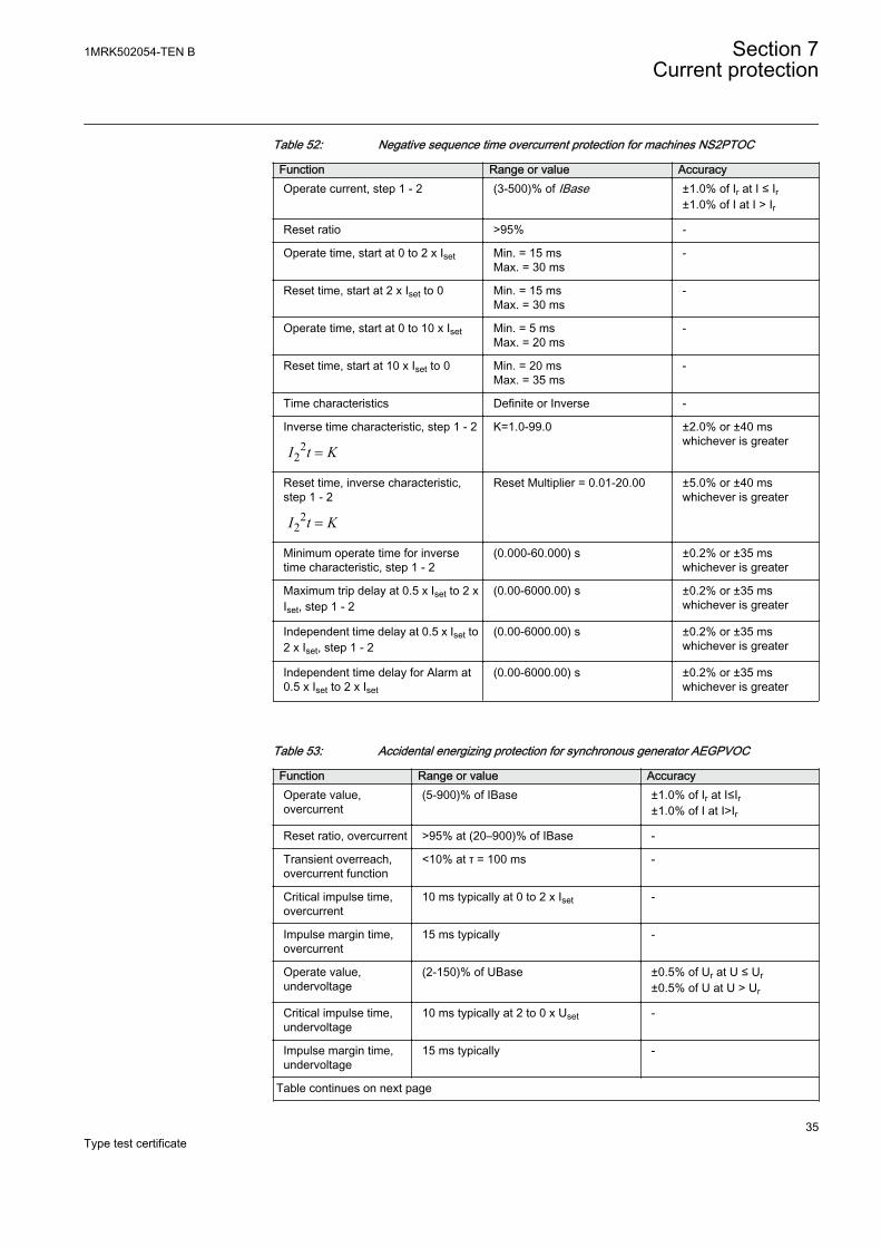
Table 52: Negative sequence time overcurrent protection for machines NS2PTOC
Function Range or value AccuracyOperate current, step 1 - 2 (3-500)% of IBase ±1.0% of Ir at I ≤ Ir
±1.0% of I at I > Ir
Reset ratio >95% -
Operate time, start at 0 to 2 x Iset Min. = 15 msMax. = 30 ms
-
Reset time, start at 2 x Iset to 0 Min. = 15 msMax. = 30 ms
-
Operate time, start at 0 to 10 x Iset Min. = 5 msMax. = 20 ms
-
Reset time, start at 10 x Iset to 0 Min. = 20 msMax. = 35 ms
-
Time characteristics Definite or Inverse -
Inverse time characteristic, step 1 - 22
2I t K=
K=1.0-99.0 ±2.0% or ±40 mswhichever is greater
Reset time, inverse characteristic,step 1 - 2
22I t K=
Reset Multiplier = 0.01-20.00 ±5.0% or ±40 mswhichever is greater
Minimum operate time for inversetime characteristic, step 1 - 2
(0.000-60.000) s ±0.2% or ±35 mswhichever is greater
Maximum trip delay at 0.5 x Iset to 2 xIset, step 1 - 2
(0.00-6000.00) s ±0.2% or ±35 mswhichever is greater
Independent time delay at 0.5 x Iset to2 x Iset, step 1 - 2
(0.00-6000.00) s ±0.2% or ±35 mswhichever is greater
Independent time delay for Alarm at0.5 x Iset to 2 x Iset
(0.00-6000.00) s ±0.2% or ±35 mswhichever is greater
Table 53: Accidental energizing protection for synchronous generator AEGPVOC
Function Range or value AccuracyOperate value,overcurrent
(5-900)% of IBase ±1.0% of Ir at I≤Ir±1.0% of I at I>Ir
Reset ratio, overcurrent >95% at (20–900)% of IBase -
Transient overreach,overcurrent function
<10% at τ = 100 ms -
Critical impulse time,overcurrent
10 ms typically at 0 to 2 x Iset -
Impulse margin time,overcurrent
15 ms typically -
Operate value,undervoltage
(2-150)% of UBase ±0.5% of Ur at U ≤ Ur±0.5% of U at U > Ur
Critical impulse time,undervoltage
10 ms typically at 2 to 0 x Uset -
Impulse margin time,undervoltage
15 ms typically -
Table continues on next page
1MRK502054-TEN B Section 7Current protection
35Type test certificate
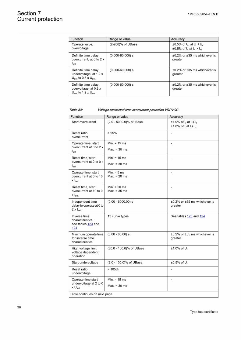
Function Range or value AccuracyOperate value,overvoltage
(2-200)% of UBase ±0.5% of Ur at U ≤ Ur±0.5% of U at U > Ur
Definite time delay,overcurrent, at 0 to 2 xIset
(0.000-60.000) s ±0.2% or ±35 ms whichever isgreater
Definite time delay,undervoltage, at 1.2 xUset to 0.8 x Uset
(0.000-60.000) s ±0.2% or ±35 ms whichever isgreater
Definite time delay,overvoltage, at 0.8 xUset to 1.2 x Uset
(0.000-60.000) s ±0.2% or ±35 ms whichever isgreater
Table 54: Voltage-restrained time overcurrent protection VRPVOC
Function Range or value AccuracyStart overcurrent (2.0 - 5000.0)% of IBase ±1.0% of Ir at I ≤ Ir
±1.0% of I at I > Ir
Reset ratio,overcurrent
> 95% -
Operate time, startovercurrent at 0 to 2 xIset
Min. = 15 ms -
Max. = 30 ms
Reset time, startovercurrent at 2 to 0 xIset
Min. = 15 ms -
Max. = 30 ms
Operate time, startovercurrent at 0 to 10x Iset
Min. = 5 msMax. = 20 ms
-
Reset time, startovercurrent at 10 to 0x Iset
Min. = 20 msMax. = 35 ms
-
Independent timedelay to operate at 0 to2 x Iset
(0.00 - 6000.00) s ±0.2% or ±35 ms whichever isgreater
Inverse timecharacteristics,see tables 123 and124
13 curve types See tables 123 and 124
Minimum operate timefor inverse timecharacteristics
(0.00 - 60.00) s ±0.2% or ±35 ms whichever isgreater
High voltage limit,voltage dependentoperation
(30.0 - 100.0)% of UBase ±1.0% of Ur
Start undervoltage (2.0 - 100.0)% of UBase ±0.5% of Ur
Reset ratio,undervoltage
< 105% -
Operate time startundervoltage at 2 to 0x Uset
Min. = 15 ms -
Max. = 30 ms
Table continues on next page
Section 7 1MRK502054-TEN BCurrent protection
36Type test certificate
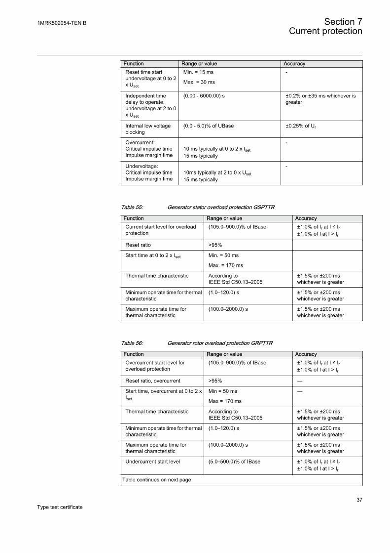
Function Range or value AccuracyReset time startundervoltage at 0 to 2x Uset
Min. = 15 ms -
Max. = 30 ms
Independent timedelay to operate,undervoltage at 2 to 0x Uset
(0.00 - 6000.00) s ±0.2% or ±35 ms whichever isgreater
Internal low voltageblocking
(0.0 - 5.0)% of UBase ±0.25% of Ur
Overcurrent:Critical impulse timeImpulse margin time
10 ms typically at 0 to 2 x Iset15 ms typically
-
Undervoltage:Critical impulse timeImpulse margin time
10ms typically at 2 to 0 x Uset15 ms typically
-
Table 55: Generator stator overload protection GSPTTR
Function Range or value AccuracyCurrent start level for overloadprotection
(105.0–900.0)% of IBase ±1.0% of Ir at I ≤ Ir±1.0% of I at I > Ir
Reset ratio >95%
Start time at 0 to 2 x Iset Min. = 50 ms
Max. = 170 ms
Thermal time characteristic According toIEEE Std C50.13–2005
±1.5% or ±200 mswhichever is greater
Minimum operate time for thermalcharacteristic
(1.0–120.0) s ±1.5% or ±200 mswhichever is greater
Maximum operate time forthermal characteristic
(100.0–2000.0) s ±1.5% or ±200 mswhichever is greater
Table 56: Generator rotor overload protection GRPTTR
Function Range or value AccuracyOvercurrent start level foroverload protection
(105.0–900.0)% of IBase ±1.0% of Ir at I ≤ Ir±1.0% of I at I > Ir
Reset ratio, overcurrent >95% —
Start time, overcurrent at 0 to 2 xIset
Min = 50 ms —
Max = 170 ms
Thermal time characteristic According toIEEE Std C50.13–2005
±1.5% or ±200 mswhichever is greater
Minimum operate time for thermalcharacteristic
(1.0–120.0) s ±1.5% or ±200 mswhichever is greater
Maximum operate time forthermal characteristic
(100.0–2000.0) s ±1.5% or ±200 mswhichever is greater
Undercurrent start level (5.0–500.0)% of IBase ±1.0% of Ir at I ≤ Ir±1.0% of I at I > Ir
Table continues on next page
1MRK502054-TEN B Section 7Current protection
37Type test certificate
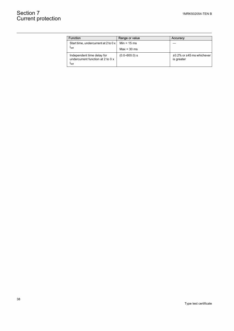
Function Range or value AccuracyStart time, undercurrent at 2 to 0 xIset
Min = 15 ms —
Max = 30 ms
Independent time delay forundercurrent function at 2 to 0 xIset
(0.0–600.0) s ±0.2% or ±45 ms whicheveris greater
Section 7 1MRK502054-TEN BCurrent protection
38Type test certificate
Section 8 Voltage protection
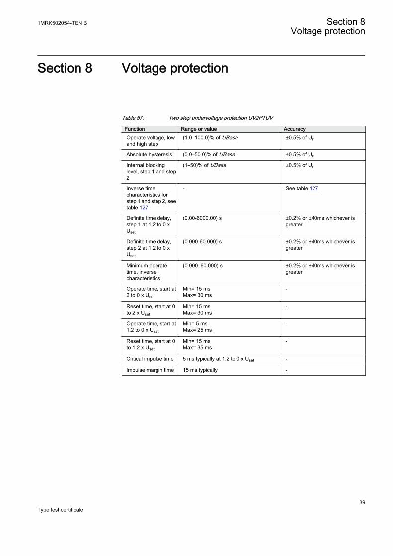
Table 57: Two step undervoltage protection UV2PTUV
Function Range or value AccuracyOperate voltage, lowand high step
(1.0–100.0)% of UBase ±0.5% of Ur
Absolute hysteresis (0.0–50.0)% of UBase ±0.5% of Ur
Internal blockinglevel, step 1 and step2
(1–50)% of UBase ±0.5% of Ur
Inverse timecharacteristics forstep 1 and step 2, seetable 127
- See table 127
Definite time delay,step 1 at 1.2 to 0 xUset
(0.00-6000.00) s ±0.2% or ±40ms whichever isgreater
Definite time delay,step 2 at 1.2 to 0 xUset
(0.000-60.000) s ±0.2% or ±40ms whichever isgreater
Minimum operatetime, inversecharacteristics
(0.000–60.000) s ±0.2% or ±40ms whichever isgreater
Operate time, start at2 to 0 x Uset
Min= 15 msMax= 30 ms
-
Reset time, start at 0to 2 x Uset
Min= 15 msMax= 30 ms
-
Operate time, start at1.2 to 0 x Uset
Min= 5 msMax= 25 ms
-
Reset time, start at 0to 1.2 x Uset
Min= 15 msMax= 35 ms
-
Critical impulse time 5 ms typically at 1.2 to 0 x Uset -
Impulse margin time 15 ms typically -
1MRK502054-TEN B Section 8Voltage protection
39Type test certificate
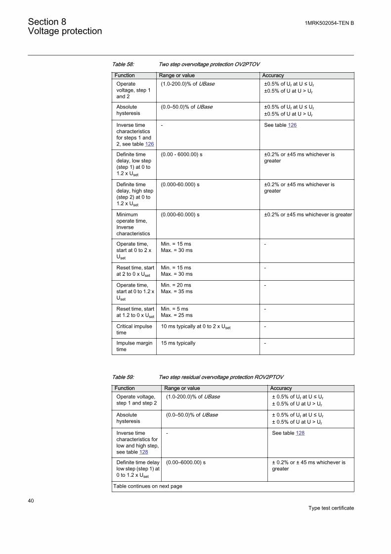
Table 58: Two step overvoltage protection OV2PTOV
Function Range or value AccuracyOperatevoltage, step 1and 2
(1.0-200.0)% of UBase ±0.5% of Ur at U ≤ Ur±0.5% of U at U > Ur
Absolutehysteresis
(0.0–50.0)% of UBase ±0.5% of Ur at U ≤ Ur±0.5% of U at U > Ur
Inverse timecharacteristicsfor steps 1 and2, see table 126
- See table 126
Definite timedelay, low step(step 1) at 0 to1.2 x Uset
(0.00 - 6000.00) s ±0.2% or ±45 ms whichever isgreater
Definite timedelay, high step(step 2) at 0 to1.2 x Uset
(0.000-60.000) s ±0.2% or ±45 ms whichever isgreater
Minimumoperate time,Inversecharacteristics
(0.000-60.000) s ±0.2% or ±45 ms whichever is greater
Operate time,start at 0 to 2 xUset
Min. = 15 msMax. = 30 ms
-
Reset time, startat 2 to 0 x Uset
Min. = 15 msMax. = 30 ms
-
Operate time,start at 0 to 1.2 xUset
Min. = 20 msMax. = 35 ms
-
Reset time, startat 1.2 to 0 x Uset
Min. = 5 msMax. = 25 ms
-
Critical impulsetime
10 ms typically at 0 to 2 x Uset -
Impulse margintime
15 ms typically -
Table 59: Two step residual overvoltage protection ROV2PTOV
Function Range or value AccuracyOperate voltage,step 1 and step 2
(1.0-200.0)% of UBase ± 0.5% of Ur at U ≤ Ur± 0.5% of U at U > Ur
Absolutehysteresis
(0.0–50.0)% of UBase ± 0.5% of Ur at U ≤ Ur± 0.5% of U at U > Ur
Inverse timecharacteristics forlow and high step,see table 128
- See table 128
Definite time delaylow step (step 1) at0 to 1.2 x Uset
(0.00–6000.00) s ± 0.2% or ± 45 ms whichever isgreater
Table continues on next page
Section 8 1MRK502054-TEN BVoltage protection
40Type test certificate
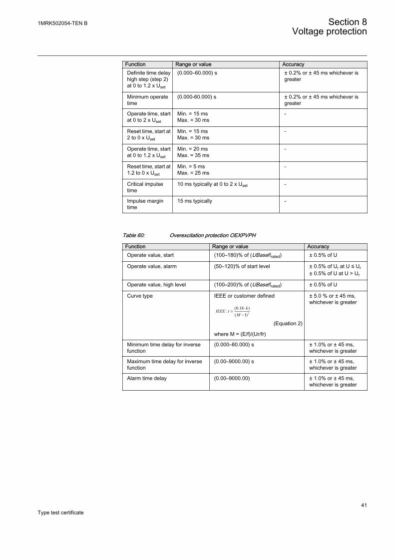
Function Range or value AccuracyDefinite time delayhigh step (step 2)at 0 to 1.2 x Uset
(0.000–60.000) s ± 0.2% or ± 45 ms whichever isgreater
Minimum operatetime
(0.000-60.000) s ± 0.2% or ± 45 ms whichever isgreater
Operate time, startat 0 to 2 x Uset
Min. = 15 msMax. = 30 ms
-
Reset time, start at2 to 0 x Uset
Min. = 15 msMax. = 30 ms
-
Operate time, startat 0 to 1.2 x Uset
Min. = 20 msMax. = 35 ms
-
Reset time, start at1.2 to 0 x Uset
Min. = 5 msMax. = 25 ms
-
Critical impulsetime
10 ms typically at 0 to 2 x Uset -
Impulse margintime
15 ms typically -
Table 60: Overexcitation protection OEXPVPH
Function Range or value AccuracyOperate value, start (100–180)% of (UBase/frated) ± 0.5% of U
Operate value, alarm (50–120)% of start level ± 0.5% of Ur at U ≤ Ur± 0.5% of U at U > Ur
Operate value, high level (100–200)% of (UBase/frated) ± 0.5% of U
Curve type IEEE or customer defined
2
(0.18 ):
( 1)k
IEEE tM
×=
-
EQUATION1319 V1 EN (Equation 2)
where M = (E/f)/(Ur/fr)
± 5.0 % or ± 45 ms,whichever is greater
Minimum time delay for inversefunction
(0.000–60.000) s ± 1.0% or ± 45 ms,whichever is greater
Maximum time delay for inversefunction
(0.00–9000.00) s ± 1.0% or ± 45 ms,whichever is greater
Alarm time delay (0.00–9000.00) ± 1.0% or ± 45 ms,whichever is greater
1MRK502054-TEN B Section 8Voltage protection
41Type test certificate
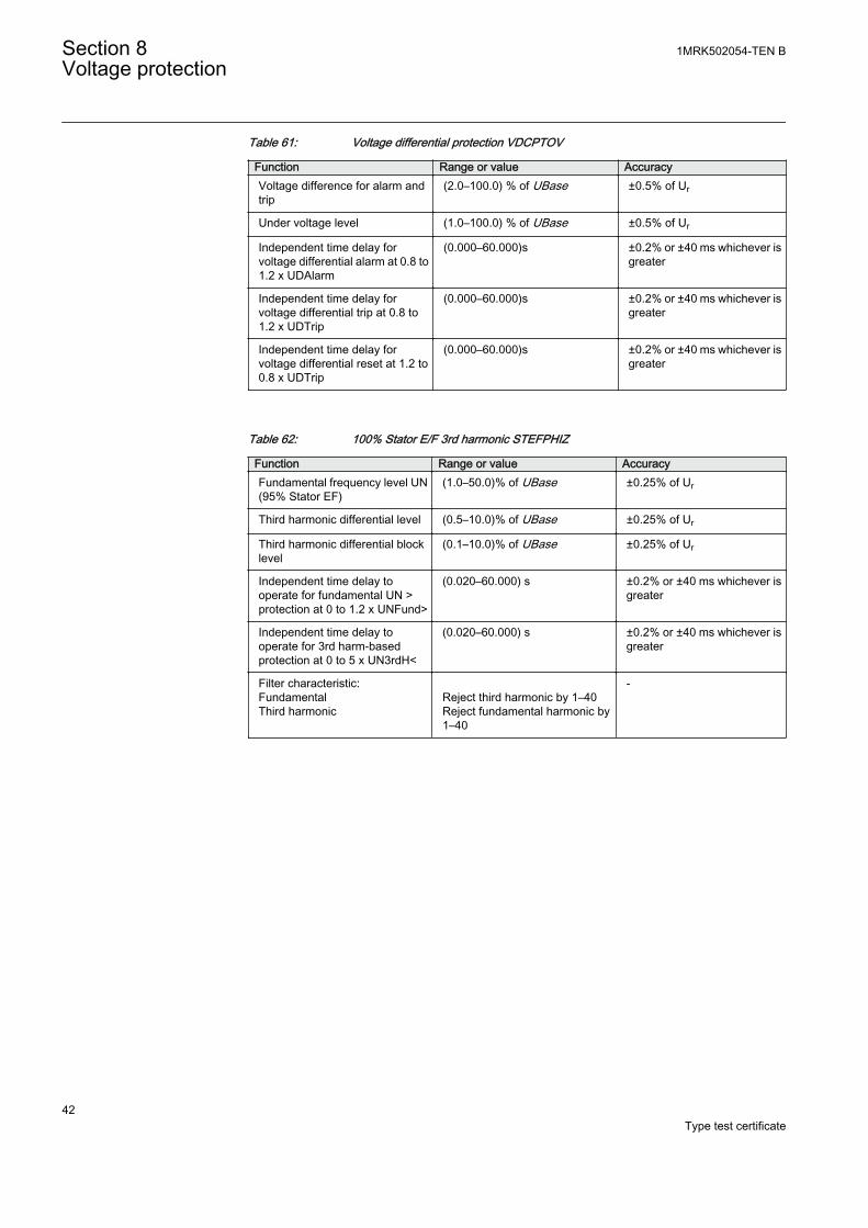
Table 61: Voltage differential protection VDCPTOV
Function Range or value AccuracyVoltage difference for alarm andtrip
(2.0–100.0) % of UBase ±0.5% of Ur
Under voltage level (1.0–100.0) % of UBase ±0.5% of Ur
Independent time delay forvoltage differential alarm at 0.8 to1.2 x UDAlarm
(0.000–60.000)s ±0.2% or ±40 ms whichever isgreater
Independent time delay forvoltage differential trip at 0.8 to1.2 x UDTrip
(0.000–60.000)s ±0.2% or ±40 ms whichever isgreater
Independent time delay forvoltage differential reset at 1.2 to0.8 x UDTrip
(0.000–60.000)s ±0.2% or ±40 ms whichever isgreater
Table 62: 100% Stator E/F 3rd harmonic STEFPHIZ
Function Range or value AccuracyFundamental frequency level UN(95% Stator EF)
(1.0–50.0)% of UBase ±0.25% of Ur
Third harmonic differential level (0.5–10.0)% of UBase ±0.25% of Ur
Third harmonic differential blocklevel
(0.1–10.0)% of UBase ±0.25% of Ur
Independent time delay tooperate for fundamental UN >protection at 0 to 1.2 x UNFund>
(0.020–60.000) s ±0.2% or ±40 ms whichever isgreater
Independent time delay tooperate for 3rd harm-basedprotection at 0 to 5 x UN3rdH<
(0.020–60.000) s ±0.2% or ±40 ms whichever isgreater
Filter characteristic:FundamentalThird harmonic
Reject third harmonic by 1–40Reject fundamental harmonic by1–40
-
Section 8 1MRK502054-TEN BVoltage protection
42Type test certificate
Section 9 Frequency protection
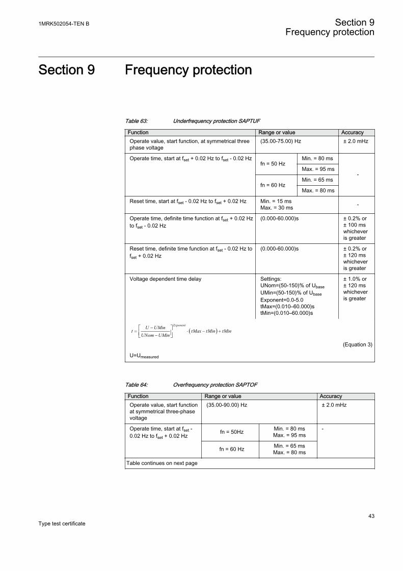
Table 63: Underfrequency protection SAPTUF
Function Range or value AccuracyOperate value, start function, at symmetrical threephase voltage
(35.00-75.00) Hz ± 2.0 mHz
Operate time, start at fset + 0.02 Hz to fset - 0.02 Hzfn = 50 Hz
Min. = 80 ms
-Max. = 95 ms
fn = 60 HzMin. = 65 ms
Max. = 80 ms
Reset time, start at fset - 0.02 Hz to fset + 0.02 Hz Min. = 15 msMax. = 30 ms -
Operate time, definite time function at fset + 0.02 Hzto fset - 0.02 Hz
(0.000-60.000)s ± 0.2% or± 100 mswhicheveris greater
Reset time, definite time function at fset - 0.02 Hz tofset + 0.02 Hz
(0.000-60.000)s ± 0.2% or± 120 mswhicheveris greater
Voltage dependent time delay Settings:UNom=(50-150)% of UbaseUMin=(50-150)% of UbaseExponent=0.0-5.0tMax=(0.010–60.000)stMin=(0.010–60.000)s
± 1.0% or± 120 mswhicheveris greater
( )ExponentU UMin
t tMax tMin tMinUNom UMin
-= × - +
-é ùê úë û
EQUATION1182 V1 EN (Equation 3)
U=Umeasured
Table 64: Overfrequency protection SAPTOF
Function Range or value AccuracyOperate value, start functionat symmetrical three-phasevoltage
(35.00-90.00) Hz ± 2.0 mHz
Operate time, start at fset -0.02 Hz to fset + 0.02 Hz
fn = 50Hz Min. = 80 msMax. = 95 ms
-
fn = 60 Hz Min. = 65 msMax. = 80 ms
Table continues on next page
1MRK502054-TEN B Section 9Frequency protection
43Type test certificate
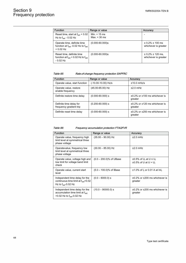
Function Range or value AccuracyReset time, start at fset + 0.02Hz to fset - 0.02 Hz
Min. = 15 msMax. = 30 ms
-
Operate time, definite timefunction at fset -0.02 Hz to fset+ 0.02 Hz
(0.000-60.000)s ± 0.2% ± 100 mswhichever is greater
Reset time, definite timefunction at fset + 0.02 Hz to fset- 0.02 Hz
(0.000-60.000)s ± 0.2% ± 120 ms,whichever is greater
Table 65: Rate-of-change frequency protection SAPFRC
Function Range or value AccuracyOperate value, start function (-10.00-10.00) Hz/s ±10.0 mHz/s
Operate value, restoreenable frequency
(45.00-65.00) Hz ±2.0 mHz
Definite restore time delay (0.000-60.000) s ±0.2% or ±100 ms whichever isgreater
Definite time delay forfrequency gradient trip
(0.200-60.000) s ±0.2% or ±120 ms whichever isgreater
Definite reset time delay (0.000-60.000) s ±0.2% or ±250 ms whichever isgreater
Table 66: Frequency accumulation protection FTAQFVR
Function Range or value AccuracyOperate value, frequency highlimit level at symmetrical threephase voltage
(35.00 – 90.00) Hz ±2.0 mHz
Operatevalue, frequency lowlimit level at symmetrical threephase voltage
(30.00 – 85.00) Hz ±2.0 mHz
Operate value, voltage high andlow limit for voltage band limitcheck
(0.0 – 200.0)% of UBase ±0.5% of Ur at U ≤ Ur±0.5% of U at U > Ur
Operate value, current startlevel
(5.0 – 100.0)% of IBase ±1.0% of Ir or 0.01 A at I≤Ir
Independent time delay for thecontinuous time limit at fset+0.02Hz to fset-0.02 Hz
(0.0 – 6000.0) s ±0.2% or ±200 ms whichever isgreater
Independent time delay for theaccumulation time limit at fset+0.02 Hz to fset-0.02 Hz
(10.0 – 90000.0) s ±0.2% or ±200 ms whichever isgreater
Section 9 1MRK502054-TEN BFrequency protection
44Type test certificate
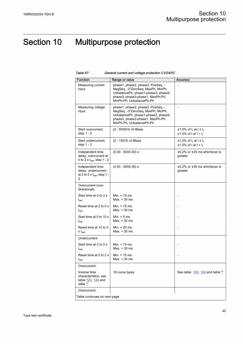
Section 10 Multipurpose protection
Table 67: General current and voltage protection CVGAPC
Function Range or value AccuracyMeasuring currentinput
phase1, phase2, phase3, PosSeq, -NegSeq, -3*ZeroSeq, MaxPh, MinPh,UnbalancePh, phase1-phase2, phase2-phase3, phase3-phase1, MaxPh-Ph,MinPh-Ph, UnbalancePh-Ph
-
Measuring voltageinput
phase1, phase2, phase3, PosSeq, -NegSeq, -3*ZeroSeq, MaxPh, MinPh,UnbalancePh, phase1-phase2, phase2-phase3, phase3-phase1, MaxPh-Ph,MinPh-Ph, UnbalancePh-Ph
-
Start overcurrent,step 1 - 2
(2 - 5000)% of IBase ±1.0% of Ir at I ≤ Ir±1.0% of I at I > Ir
Start undercurrent,step 1 - 2
(2 - 150)% of IBase ±1.0% of Ir at I ≤ Ir±1.0% of I at I > Ir
Independent timedelay, overcurrent at0 to 2 x Iset, step 1 - 2
(0.00 - 6000.00) s ±0.2% or ±35 ms whichever isgreater
Independent timedelay, undercurrentat 2 to 0 x Iset, step 1 -2
(0.00 - 6000.00) s ±0.2% or ±35 ms whichever isgreater
Overcurrent (non-directional):
Start time at 0 to 2 xIset
Min. = 15 msMax. = 30 ms
-
Reset time at 2 to 0 xIset
Min. = 15 msMax. = 30 ms
-
Start time at 0 to 10 xIset
Min. = 5 msMax. = 20 ms
-
Reset time at 10 to 0x Iset
Min. = 20 msMax. = 35 ms
-
Undercurrent:
Start time at 2 to 0 xIset
Min. = 15 msMax. = 30 ms
-
Reset time at 0 to 2 xIset
Min. = 15 msMax. = 30 ms
-
Overcurrent:
Inverse timecharacteristics, seetable 123, 124 andtable ""
16 curve types See table 123, 124 and table ""
Overcurrent:
Table continues on next page
1MRK502054-TEN B Section 10Multipurpose protection
45Type test certificate
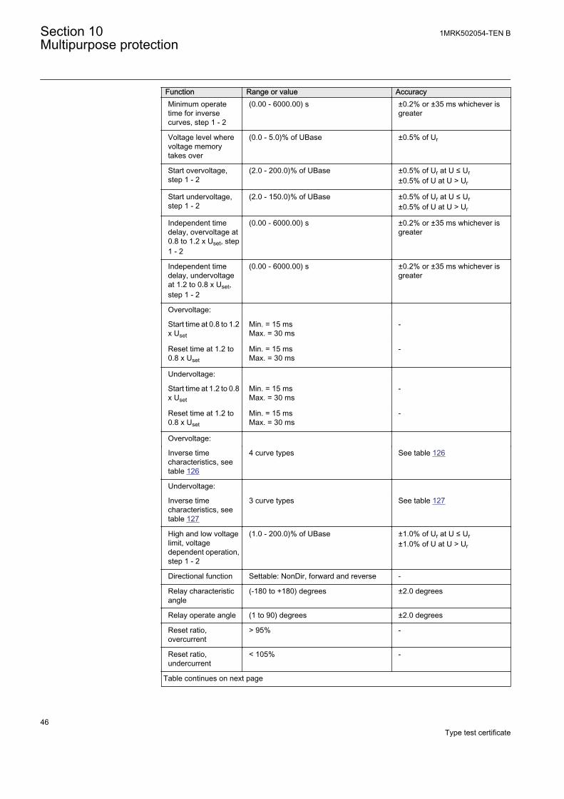
Function Range or value AccuracyMinimum operatetime for inversecurves, step 1 - 2
(0.00 - 6000.00) s ±0.2% or ±35 ms whichever isgreater
Voltage level wherevoltage memorytakes over
(0.0 - 5.0)% of UBase ±0.5% of Ur
Start overvoltage,step 1 - 2
(2.0 - 200.0)% of UBase ±0.5% of Ur at U ≤ Ur±0.5% of U at U > Ur
Start undervoltage,step 1 - 2
(2.0 - 150.0)% of UBase ±0.5% of Ur at U ≤ Ur±0.5% of U at U > Ur
Independent timedelay, overvoltage at0.8 to 1.2 x Uset, step1 - 2
(0.00 - 6000.00) s ±0.2% or ±35 ms whichever isgreater
Independent timedelay, undervoltageat 1.2 to 0.8 x Uset,step 1 - 2
(0.00 - 6000.00) s ±0.2% or ±35 ms whichever isgreater
Overvoltage:
Start time at 0.8 to 1.2x Uset
Min. = 15 msMax. = 30 ms
-
Reset time at 1.2 to0.8 x Uset
Min. = 15 msMax. = 30 ms
-
Undervoltage:
Start time at 1.2 to 0.8x Uset
Min. = 15 msMax. = 30 ms
-
Reset time at 1.2 to0.8 x Uset
Min. = 15 msMax. = 30 ms
-
Overvoltage:
Inverse timecharacteristics, seetable 126
4 curve types See table 126
Undervoltage:
Inverse timecharacteristics, seetable 127
3 curve types See table 127
High and low voltagelimit, voltagedependent operation,step 1 - 2
(1.0 - 200.0)% of UBase ±1.0% of Ur at U ≤ Ur±1.0% of U at U > Ur
Directional function Settable: NonDir, forward and reverse -
Relay characteristicangle
(-180 to +180) degrees ±2.0 degrees
Relay operate angle (1 to 90) degrees ±2.0 degrees
Reset ratio,overcurrent
> 95% -
Reset ratio,undercurrent
< 105% -
Table continues on next page
Section 10 1MRK502054-TEN BMultipurpose protection
46Type test certificate
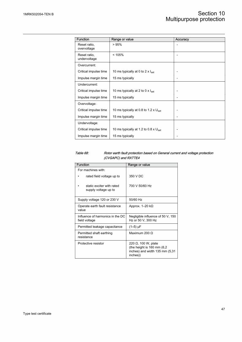
Function Range or value AccuracyReset ratio,overvoltage
> 95% -
Reset ratio,undervoltage
< 105% -
Overcurrent:
Critical impulse time 10 ms typically at 0 to 2 x Iset -
Impulse margin time 15 ms typically -
Undercurrent:
Critical impulse time 10 ms typically at 2 to 0 x Iset -
Impulse margin time 15 ms typically -
Overvoltage:
Critical impulse time 10 ms typically at 0.8 to 1.2 x Uset -
Impulse margin time 15 ms typically -
Undervoltage:
Critical impulse time 10 ms typically at 1.2 to 0.8 x Uset -
Impulse margin time 15 ms typically -
Table 68: Rotor earth fault protection based on General current and voltage protection(CVGAPC) and RXTTE4
Function Range or valueFor machines with:
• rated field voltage up to 350 V DC
• static exciter with ratedsupply voltage up to
700 V 50/60 Hz
Supply voltage 120 or 230 V 50/60 Hz
Operate earth fault resistancevalue
Approx. 1–20 kΩ
Influence of harmonics in the DCfield voltage
Negligible influence of 50 V, 150Hz or 50 V, 300 Hz
Permitted leakage capacitance (1–5) μF
Permitted shaft earthingresistance
Maximum 200 Ω
Protective resistor 220 Ω, 100 W, plate(the height is 160 mm (6,2inches) and width 135 mm (5,31inches))
1MRK502054-TEN B Section 10Multipurpose protection
47Type test certificate

48
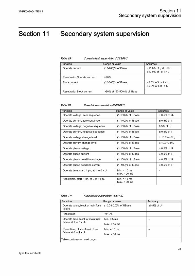
Section 11 Secondary system supervision
Table 69: Current circuit supervision CCSSPVC
Function Range or value AccuracyOperate current (10-200)% of IBase ±10.0% of Ir at I ≤ Ir
±10.0% of I at I > Ir
Reset ratio, Operate current >90%
Block current (20-500)% of IBase ±5.0% of Ir at I ≤ Ir±5.0% of I at I > Ir
Reset ratio, Block current >90% at (50-500)% of IBase
Table 70: Fuse failure supervision FUFSPVC
Function Range or value AccuracyOperate voltage, zero sequence (1-100)% of UBase ± 0.5% of Ur
Operate current, zero sequence (1–100)% of IBase ± 0.5% of Ir
Operate voltage, negative sequence (1-100)% of UBase 0.5% of Ur
Operate current, negative sequence (1–100)% of IBase ± 0.5% of Ir
Operate voltage change level (1-100)% of UBase ± 10.0% of Ur
Operate current change level (1–100)% of IBase ± 10.0% of Ir
Operate phase voltage (1-100)% of UBase ± 0.5% of Ur
Operate phase current (1–100)% of IBase ± 0.5% of Ir
Operate phase dead line voltage (1-100)% of UBase ± 0.5% of Ur
Operate phase dead line current (1–100)% of IBase ± 0.5% of Ir
Operate time, start, 1 ph, at 1 to 0 x Ur Min. = 10 msMax. = 25 ms
-
Reset time, start, 1 ph, at 0 to 1 x Ur Min. = 15 msMax. = 30 ms
-
Table 71: Fuse failure supervision VDSPVC
Function Range or value AccuracyOperate value, block of main fusefailure
(10.0-80.0)% of UBase ±0.5% of Ur
Reset ratio <110%
Operate time, block of main fusefailure at 1 to 0 x Ur
Min. = 5 ms –
Max. = 15 ms
Reset time, block of main fusefailure at 0 to 1 x Ur
Min. = 15 ms –
Max. = 30 ms
Table continues on next page
1MRK502054-TEN B Section 11Secondary system supervision
49Type test certificate
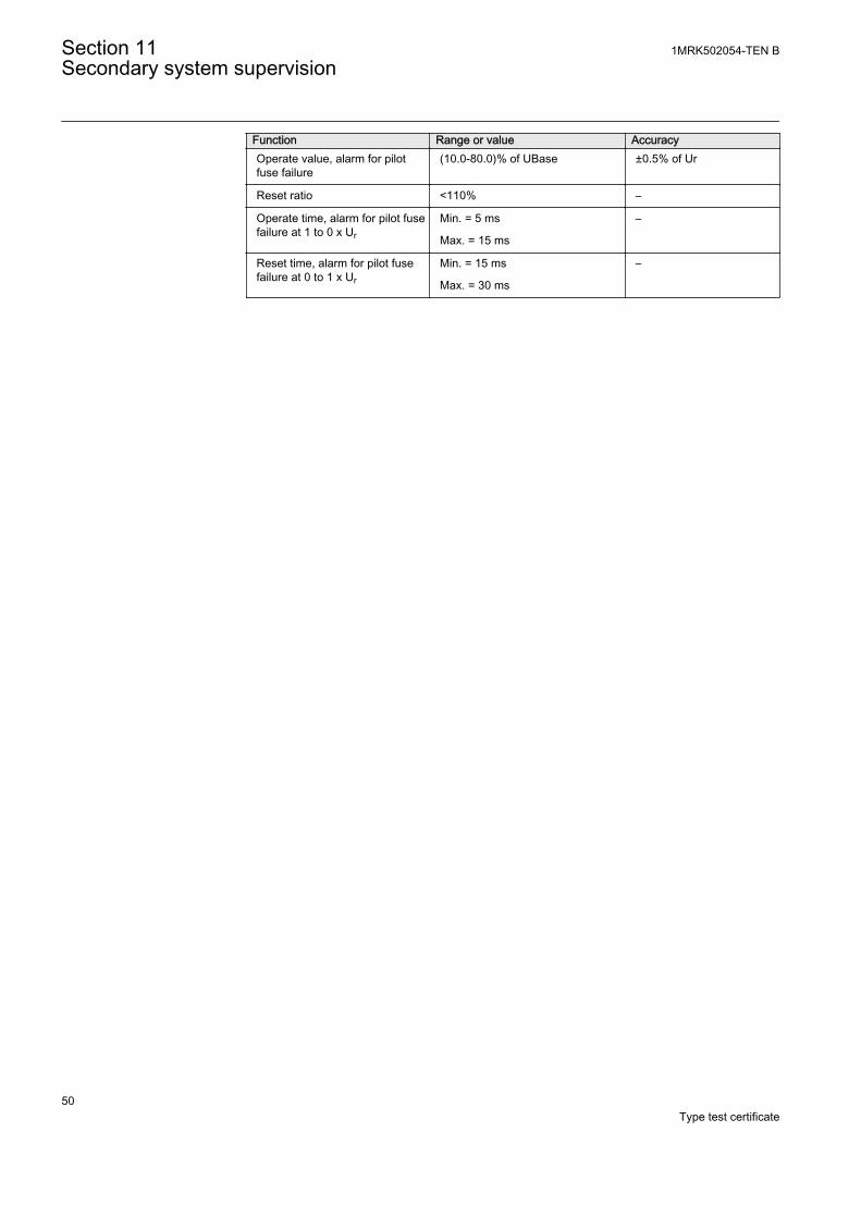
Function Range or value AccuracyOperate value, alarm for pilotfuse failure
(10.0-80.0)% of UBase ±0.5% of Ur
Reset ratio <110% –
Operate time, alarm for pilot fusefailure at 1 to 0 x Ur
Min. = 5 ms –
Max. = 15 ms
Reset time, alarm for pilot fusefailure at 0 to 1 x Ur
Min. = 15 ms –
Max. = 30 ms
Section 11 1MRK502054-TEN BSecondary system supervision
50Type test certificate
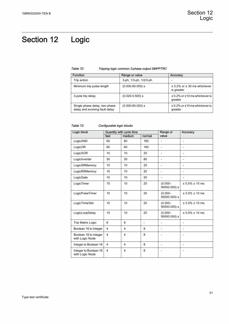
Section 12 Logic
Table 72: Tripping logic common 3-phase output SMPPTRC
Function Range or value AccuracyTrip action 3-ph, 1/3-ph, 1/2/3-ph -
Minimum trip pulse length (0.000-60.000) s ± 0.2% or ± 30 ms whicheveris greater
3-pole trip delay (0.020-0.500) s ± 0.2% or ±10 ms whichever isgreater
Single phase delay, two phasedelay and evolving fault delay
(0.000-60.000) s ± 0.2% or ±10 ms whichever isgreater
Table 73: Configurable logic blocks
Logic block Quantity with cycle time Range orvalue
Accuracyfast medium normal
LogicAND 60 60 160 - -
LogicOR 60 60 160 - -
LogicXOR 10 10 20 - -
LogicInverter 30 30 80 - -
LogicSRMemory 10 10 20 - -
LogicRSMemory 10 10 20 - -
LogicGate 10 10 20 - -
LogicTimer 10 10 20 (0.000–90000.000) s
± 0.5% ± 10 ms
LogicPulseTimer 10 10 20 (0.000–90000.000) s
± 0.5% ± 10 ms
LogicTimerSet 10 10 20 (0.000–90000.000) s
± 0.5% ± 10 ms
LogicLoopDelay 10 10 20 (0.000–90000.000) s
± 0.5% ± 10 ms
Trip Matrix Logic 6 6 - - -
Boolean 16 to Integer 4 4 8 - -
Boolean 16 to integerwith Logic Node
4 4 8 - -
Integer to Boolean 16 4 4 8 - -
Integer to Boolean 16with Logic Node
4 4 8 - -
1MRK502054-TEN B Section 12Logic
51Type test certificate
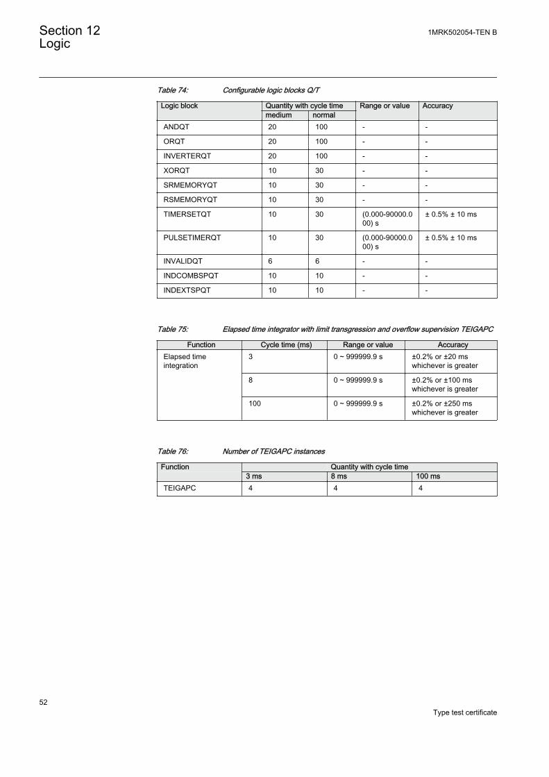
Table 74: Configurable logic blocks Q/T
Logic block Quantity with cycle time Range or value Accuracymedium normal
ANDQT 20 100 - -
ORQT 20 100 - -
INVERTERQT 20 100 - -
XORQT 10 30 - -
SRMEMORYQT 10 30 - -
RSMEMORYQT 10 30 - -
TIMERSETQT 10 30 (0.000-90000.000) s
± 0.5% ± 10 ms
PULSETIMERQT 10 30 (0.000-90000.000) s
± 0.5% ± 10 ms
INVALIDQT 6 6 - -
INDCOMBSPQT 10 10 - -
INDEXTSPQT 10 10 - -
Table 75: Elapsed time integrator with limit transgression and overflow supervision TEIGAPC
Function Cycle time (ms) Range or value AccuracyElapsed timeintegration
3 0 ~ 999999.9 s ±0.2% or ±20 mswhichever is greater
8 0 ~ 999999.9 s ±0.2% or ±100 mswhichever is greater
100 0 ~ 999999.9 s ±0.2% or ±250 mswhichever is greater
Table 76: Number of TEIGAPC instances
Function Quantity with cycle time 3 ms 8 ms 100 msTEIGAPC 4 4 4
Section 12 1MRK502054-TEN BLogic
52Type test certificate
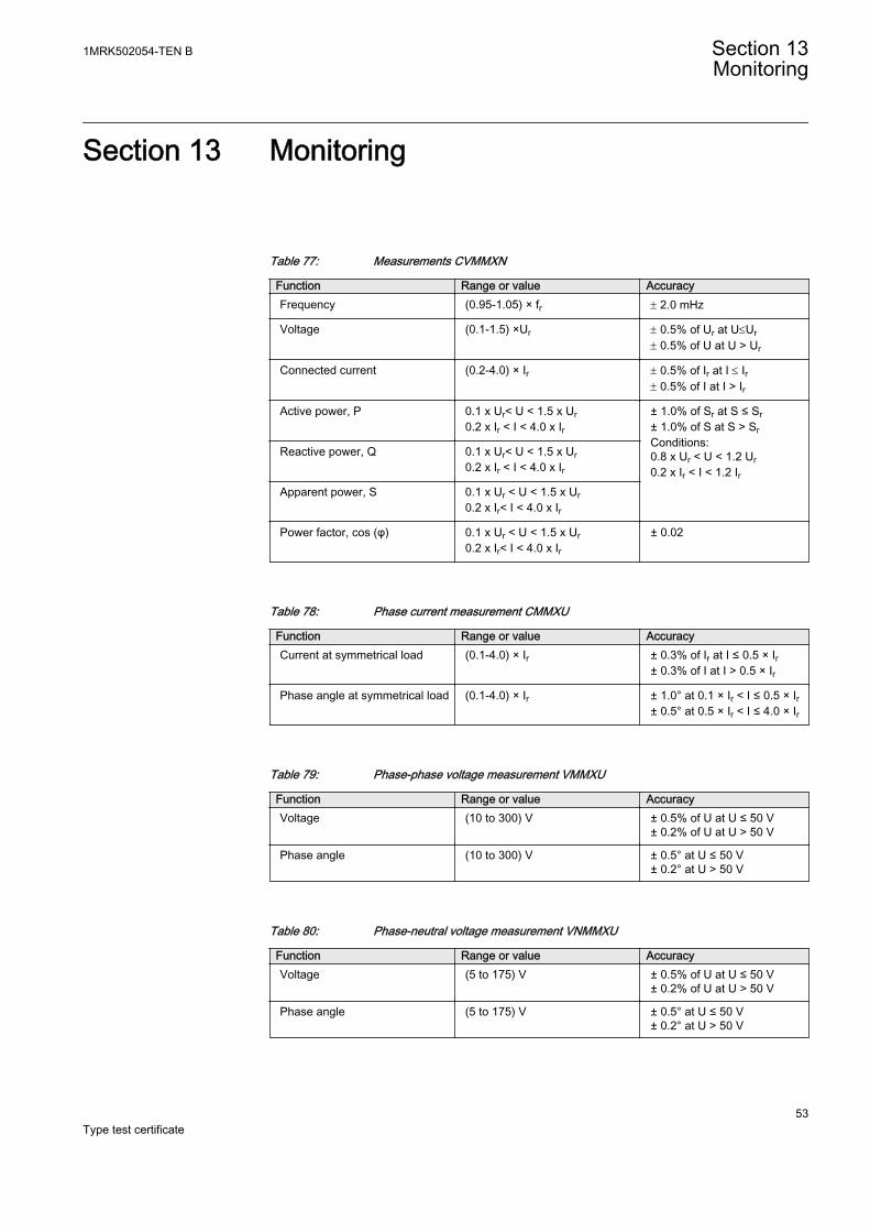
Section 13 Monitoring
Table 77: Measurements CVMMXN
Function Range or value AccuracyFrequency (0.95-1.05) × fr ± 2.0 mHz
Voltage (0.1-1.5) ×Ur ± 0.5% of Ur at U£Ur± 0.5% of U at U > Ur
Connected current (0.2-4.0) × Ir ± 0.5% of Ir at I £ Ir± 0.5% of I at I > Ir
Active power, P 0.1 x Ur< U < 1.5 x Ur0.2 x Ir < I < 4.0 x Ir
± 1.0% of Sr at S ≤ Sr± 1.0% of S at S > SrConditions:0.8 x Ur < U < 1.2 Ur0.2 x Ir < I < 1.2 Ir
Reactive power, Q 0.1 x Ur< U < 1.5 x Ur0.2 x Ir < I < 4.0 x Ir
Apparent power, S 0.1 x Ur < U < 1.5 x Ur0.2 x Ir< I < 4.0 x Ir
Power factor, cos (φ) 0.1 x Ur < U < 1.5 x Ur0.2 x Ir< I < 4.0 x Ir
± 0.02
Table 78: Phase current measurement CMMXU
Function Range or value AccuracyCurrent at symmetrical load (0.1-4.0) × Ir ± 0.3% of Ir at I ≤ 0.5 × Ir
± 0.3% of I at I > 0.5 × Ir
Phase angle at symmetrical load (0.1-4.0) × Ir ± 1.0° at 0.1 × Ir < I ≤ 0.5 × Ir± 0.5° at 0.5 × Ir < I ≤ 4.0 × Ir
Table 79: Phase-phase voltage measurement VMMXU
Function Range or value AccuracyVoltage (10 to 300) V ± 0.5% of U at U ≤ 50 V
± 0.2% of U at U > 50 V
Phase angle (10 to 300) V ± 0.5° at U ≤ 50 V± 0.2° at U > 50 V
Table 80: Phase-neutral voltage measurement VNMMXU
Function Range or value AccuracyVoltage (5 to 175) V ± 0.5% of U at U ≤ 50 V
± 0.2% of U at U > 50 V
Phase angle (5 to 175) V ± 0.5° at U ≤ 50 V± 0.2° at U > 50 V
1MRK502054-TEN B Section 13Monitoring
53Type test certificate
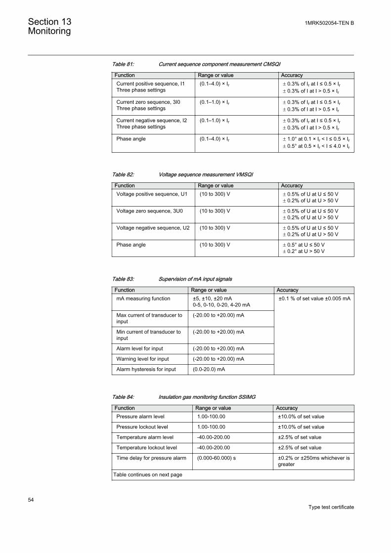
Table 81: Current sequence component measurement CMSQI
Function Range or value AccuracyCurrent positive sequence, I1Three phase settings
(0.1–4.0) × Ir ± 0.3% of Ir at I ≤ 0.5 × Ir± 0.3% of I at I > 0.5 × Ir
Current zero sequence, 3I0Three phase settings
(0.1–1.0) × Ir ± 0.3% of Ir at I ≤ 0.5 × Ir± 0.3% of I at I > 0.5 × Ir
Current negative sequence, I2Three phase settings
(0.1–1.0) × Ir ± 0.3% of Ir at I ≤ 0.5 × Ir± 0.3% of I at I > 0.5 × Ir
Phase angle (0.1–4.0) × Ir ± 1.0° at 0.1 × Ir < I ≤ 0.5 × Ir± 0.5° at 0.5 × Ir < I ≤ 4.0 × Ir
Table 82: Voltage sequence measurement VMSQI
Function Range or value AccuracyVoltage positive sequence, U1 (10 to 300) V ± 0.5% of U at U ≤ 50 V
± 0.2% of U at U > 50 V
Voltage zero sequence, 3U0 (10 to 300) V ± 0.5% of U at U ≤ 50 V± 0.2% of U at U > 50 V
Voltage negative sequence, U2 (10 to 300) V ± 0.5% of U at U ≤ 50 V± 0.2% of U at U > 50 V
Phase angle (10 to 300) V ± 0.5° at U ≤ 50 V± 0.2° at U > 50 V
Table 83: Supervision of mA input signals
Function Range or value AccuracymA measuring function ±5, ±10, ±20 mA
0-5, 0-10, 0-20, 4-20 mA±0.1 % of set value ±0.005 mA
Max current of transducer toinput
(-20.00 to +20.00) mA
Min current of transducer toinput
(-20.00 to +20.00) mA
Alarm level for input (-20.00 to +20.00) mA
Warning level for input (-20.00 to +20.00) mA
Alarm hysteresis for input (0.0-20.0) mA
Table 84: Insulation gas monitoring function SSIMG
Function Range or value AccuracyPressure alarm level 1.00-100.00 ±10.0% of set value
Pressure lockout level 1.00-100.00 ±10.0% of set value
Temperature alarm level -40.00-200.00 ±2.5% of set value
Temperature lockout level -40.00-200.00 ±2.5% of set value
Time delay for pressure alarm (0.000-60.000) s ±0.2% or ±250ms whichever isgreater
Table continues on next page
Section 13 1MRK502054-TEN BMonitoring
54Type test certificate
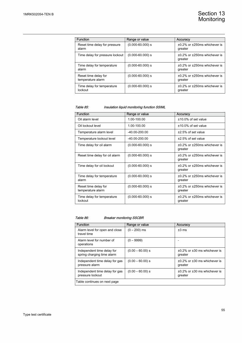
Function Range or value AccuracyReset time delay for pressurealarm
(0.000-60.000) s ±0.2% or ±250ms whichever isgreater
Time delay for pressure lockout (0.000-60.000) s ±0.2% or ±250ms whichever isgreater
Time delay for temperaturealarm
(0.000-60.000) s ±0.2% or ±250ms whichever isgreater
Reset time delay fortemperature alarm
(0.000-60.000) s ±0.2% or ±250ms whichever isgreater
Time delay for temperaturelockout
(0.000-60.000) s ±0.2% or ±250ms whichever isgreater
Table 85: Insulation liquid monitoring function SSIML
Function Range or value AccuracyOil alarm level 1.00-100.00 ±10.0% of set value
Oil lockout level 1.00-100.00 ±10.0% of set value
Temperature alarm level -40.00-200.00 ±2.5% of set value
Temperature lockout level -40.00-200.00 ±2.5% of set value
Time delay for oil alarm (0.000-60.000) s ±0.2% or ±250ms whichever isgreater
Reset time delay for oil alarm (0.000-60.000) s ±0.2% or ±250ms whichever isgreater
Time delay for oil lockout (0.000-60.000) s ±0.2% or ±250ms whichever isgreater
Time delay for temperaturealarm
(0.000-60.000) s ±0.2% or ±250ms whichever isgreater
Reset time delay fortemperature alarm
(0.000-60.000) s ±0.2% or ±250ms whichever isgreater
Time delay for temperaturelockout
(0.000-60.000) s ±0.2% or ±250ms whichever isgreater
Table 86: Breaker monitoring SSCBR
Function Range or value AccuracyAlarm level for open and closetravel time
(0 – 200) ms ±3 ms
Alarm level for number ofoperations
(0 – 9999) -
Independent time delay forspring charging time alarm
(0.00 – 60.00) s ±0.2% or ±30 ms whichever isgreater
Independent time delay for gaspressure alarm
(0.00 – 60.00) s ±0.2% or ±30 ms whichever isgreater
Independent time delay for gaspressure lockout
(0.00 – 60.00) s ±0.2% or ±30 ms whichever isgreater
Table continues on next page
1MRK502054-TEN B Section 13Monitoring
55Type test certificate
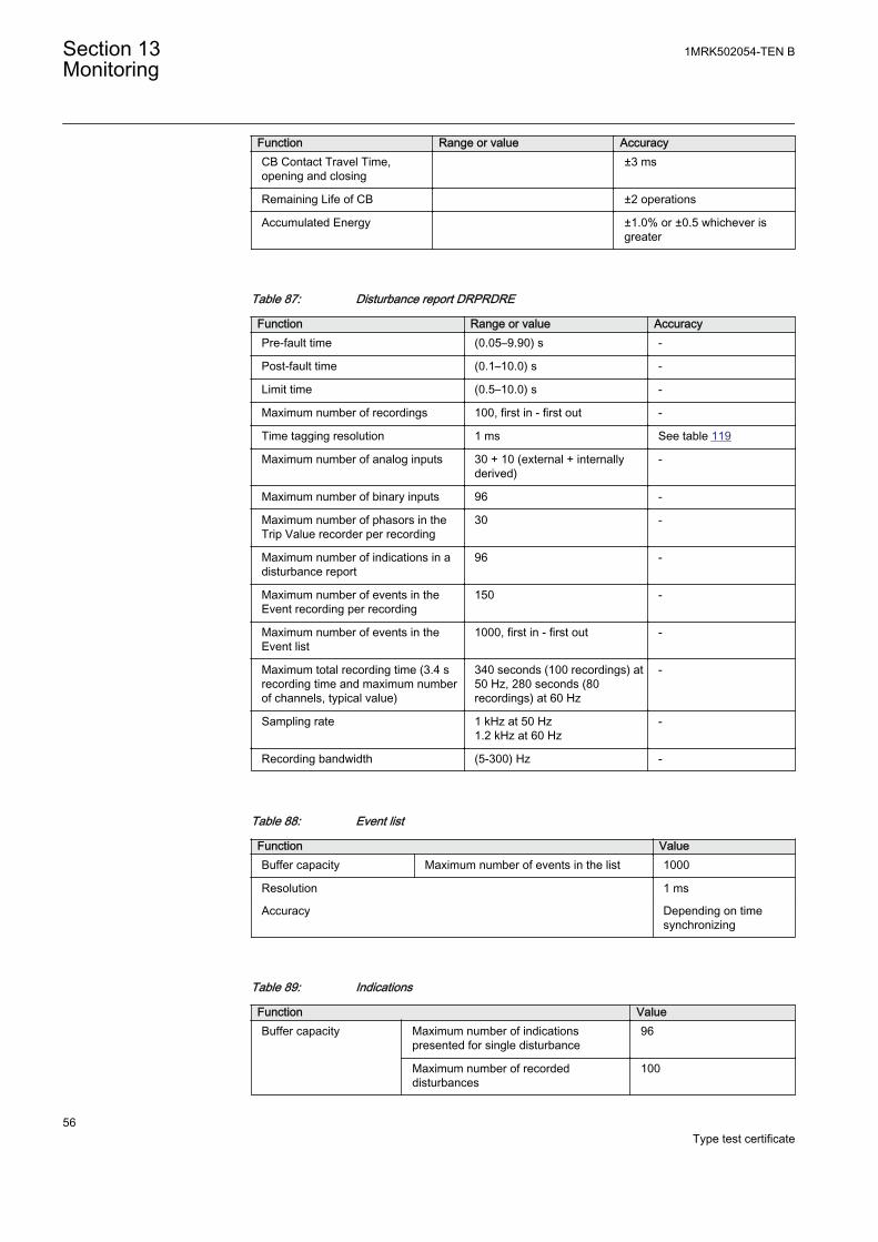
Function Range or value AccuracyCB Contact Travel Time,opening and closing
±3 ms
Remaining Life of CB ±2 operations
Accumulated Energy ±1.0% or ±0.5 whichever isgreater
Table 87: Disturbance report DRPRDRE
Function Range or value AccuracyPre-fault time (0.05–9.90) s -
Post-fault time (0.1–10.0) s -
Limit time (0.5–10.0) s -
Maximum number of recordings 100, first in - first out -
Time tagging resolution 1 ms See table 119
Maximum number of analog inputs 30 + 10 (external + internallyderived)
-
Maximum number of binary inputs 96 -
Maximum number of phasors in theTrip Value recorder per recording
30 -
Maximum number of indications in adisturbance report
96 -
Maximum number of events in theEvent recording per recording
150 -
Maximum number of events in theEvent list
1000, first in - first out -
Maximum total recording time (3.4 srecording time and maximum numberof channels, typical value)
340 seconds (100 recordings) at50 Hz, 280 seconds (80recordings) at 60 Hz
-
Sampling rate 1 kHz at 50 Hz1.2 kHz at 60 Hz
-
Recording bandwidth (5-300) Hz -
Table 88: Event list
Function ValueBuffer capacity Maximum number of events in the list 1000
Resolution 1 ms
Accuracy Depending on timesynchronizing
Table 89: Indications
Function ValueBuffer capacity Maximum number of indications
presented for single disturbance96
Maximum number of recordeddisturbances
100
Section 13 1MRK502054-TEN BMonitoring
56Type test certificate
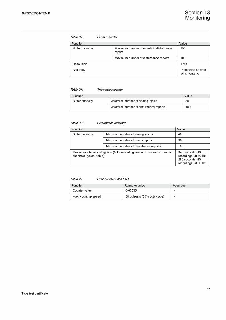
Table 90: Event recorder
Function ValueBuffer capacity Maximum number of events in disturbance
report150
Maximum number of disturbance reports 100
Resolution 1 ms
Accuracy Depending on timesynchronizing
Table 91: Trip value recorder
Function ValueBuffer capacity
Maximum number of analog inputs 30
Maximum number of disturbance reports 100
Table 92: Disturbance recorder
Function ValueBuffer capacity Maximum number of analog inputs 40
Maximum number of binary inputs 96
Maximum number of disturbance reports 100
Maximum total recording time (3.4 s recording time and maximum number ofchannels, typical value)
340 seconds (100recordings) at 50 Hz280 seconds (80recordings) at 60 Hz
Table 93: Limit counter L4UFCNT
Function Range or value AccuracyCounter value 0-65535 -
Max. count up speed 30 pulses/s (50% duty cycle) -
1MRK502054-TEN B Section 13Monitoring
57Type test certificate

58
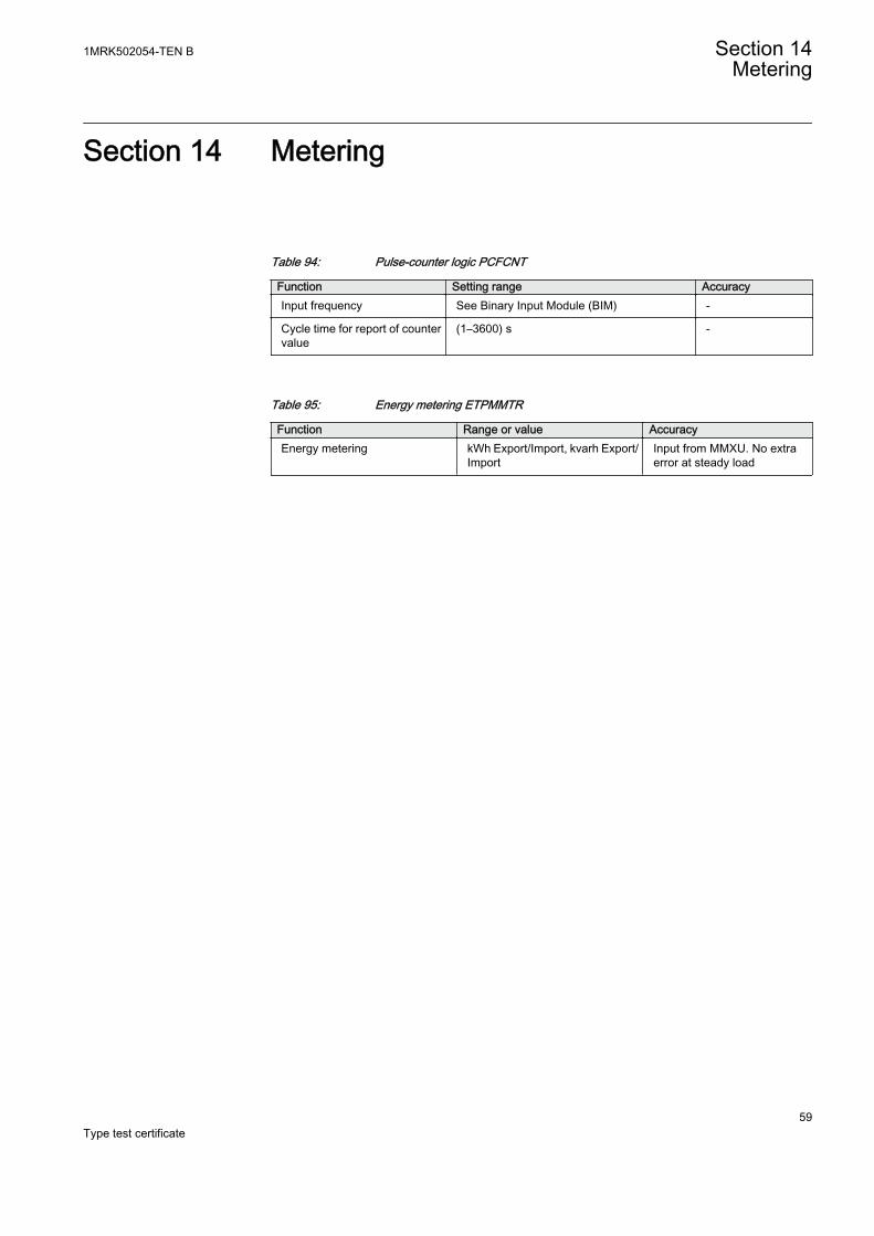
Section 14 Metering
Table 94: Pulse-counter logic PCFCNT
Function Setting range AccuracyInput frequency See Binary Input Module (BIM) -
Cycle time for report of countervalue
(1–3600) s -
Table 95: Energy metering ETPMMTR
Function Range or value AccuracyEnergy metering kWh Export/Import, kvarh Export/
ImportInput from MMXU. No extraerror at steady load
1MRK502054-TEN B Section 14Metering
59Type test certificate

60
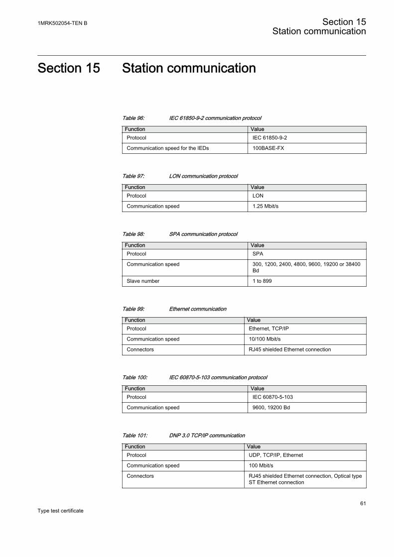
Section 15 Station communication
Table 96: IEC 61850-9-2 communication protocol
Function ValueProtocol IEC 61850-9-2
Communication speed for the IEDs 100BASE-FX
Table 97: LON communication protocol
Function ValueProtocol LON
Communication speed 1.25 Mbit/s
Table 98: SPA communication protocol
Function ValueProtocol SPA
Communication speed 300, 1200, 2400, 4800, 9600, 19200 or 38400Bd
Slave number 1 to 899
Table 99: Ethernet communication
Function ValueProtocol Ethernet, TCP/IP
Communication speed 10/100 Mbit/s
Connectors RJ45 shielded Ethernet connection
Table 100: IEC 60870-5-103 communication protocol
Function ValueProtocol IEC 60870-5-103
Communication speed 9600, 19200 Bd
Table 101: DNP 3.0 TCP/IP communication
Function ValueProtocol UDP, TCP/IP, Ethernet
Communication speed 100 Mbit/s
Connectors RJ45 shielded Ethernet connection, Optical typeST Ethernet connection
1MRK502054-TEN B Section 15Station communication
61Type test certificate
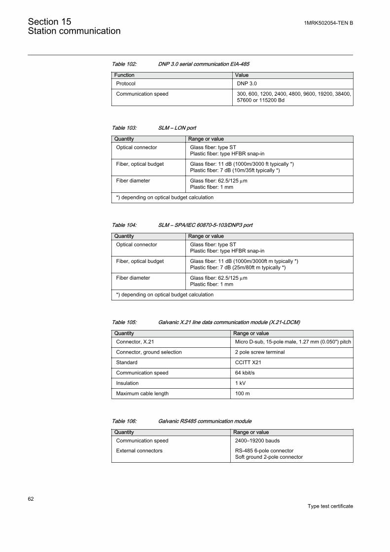
Table 102: DNP 3.0 serial communication EIA-485
Function ValueProtocol DNP 3.0
Communication speed 300, 600, 1200, 2400, 4800, 9600, 19200, 38400,57600 or 115200 Bd
Table 103: SLM – LON port
Quantity Range or valueOptical connector Glass fiber: type ST
Plastic fiber: type HFBR snap-in
Fiber, optical budget Glass fiber: 11 dB (1000m/3000 ft typically *)Plastic fiber: 7 dB (10m/35ft typically *)
Fiber diameter Glass fiber: 62.5/125 mmPlastic fiber: 1 mm
*) depending on optical budget calculation
Table 104: SLM – SPA/IEC 60870-5-103/DNP3 port
Quantity Range or valueOptical connector Glass fiber: type ST
Plastic fiber: type HFBR snap-in
Fiber, optical budget Glass fiber: 11 dB (1000m/3000ft m typically *)Plastic fiber: 7 dB (25m/80ft m typically *)
Fiber diameter Glass fiber: 62.5/125 mmPlastic fiber: 1 mm
*) depending on optical budget calculation
Table 105: Galvanic X.21 line data communication module (X.21-LDCM)
Quantity Range or valueConnector, X.21 Micro D-sub, 15-pole male, 1.27 mm (0.050") pitch
Connector, ground selection 2 pole screw terminal
Standard CCITT X21
Communication speed 64 kbit/s
Insulation 1 kV
Maximum cable length 100 m
Table 106: Galvanic RS485 communication module
Quantity Range or valueCommunication speed 2400–19200 bauds
External connectors RS-485 6-pole connectorSoft ground 2-pole connector
Section 15 1MRK502054-TEN BStation communication
62Type test certificate
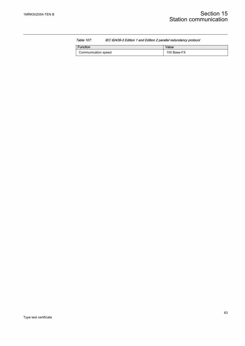
Table 107: IEC 62439-3 Edition 1 and Edition 2 parallel redundancy protocol
Function ValueCommunication speed 100 Base-FX
1MRK502054-TEN B Section 15Station communication
63Type test certificate

64
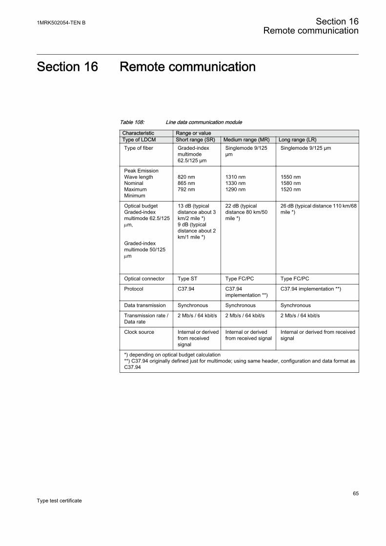
Section 16 Remote communication
Table 108: Line data communication module
Characteristic Range or valueType of LDCM Short range (SR) Medium range (MR) Long range (LR)Type of fiber Graded-index
multimode62.5/125 µm
Singlemode 9/125µm
Singlemode 9/125 µm
Peak EmissionWave lengthNominalMaximumMinimum
820 nm865 nm792 nm
1310 nm1330 nm1290 nm
1550 nm1580 nm1520 nm
Optical budgetGraded-indexmultimode 62.5/125mm, Graded-indexmultimode 50/125mm
13 dB (typicaldistance about 3km/2 mile *)9 dB (typicaldistance about 2km/1 mile *)
22 dB (typicaldistance 80 km/50mile *)
26 dB (typical distance 110 km/68mile *)
Optical connector Type ST Type FC/PC Type FC/PC
Protocol C37.94 C37.94implementation **)
C37.94 implementation **)
Data transmission Synchronous Synchronous Synchronous
Transmission rate /Data rate
2 Mb/s / 64 kbit/s 2 Mb/s / 64 kbit/s 2 Mb/s / 64 kbit/s
Clock source Internal or derivedfrom receivedsignal
Internal or derivedfrom received signal
Internal or derived from receivedsignal
*) depending on optical budget calculation**) C37.94 originally defined just for multimode; using same header, configuration and data format asC37.94
1MRK502054-TEN B Section 16Remote communication
65Type test certificate

66
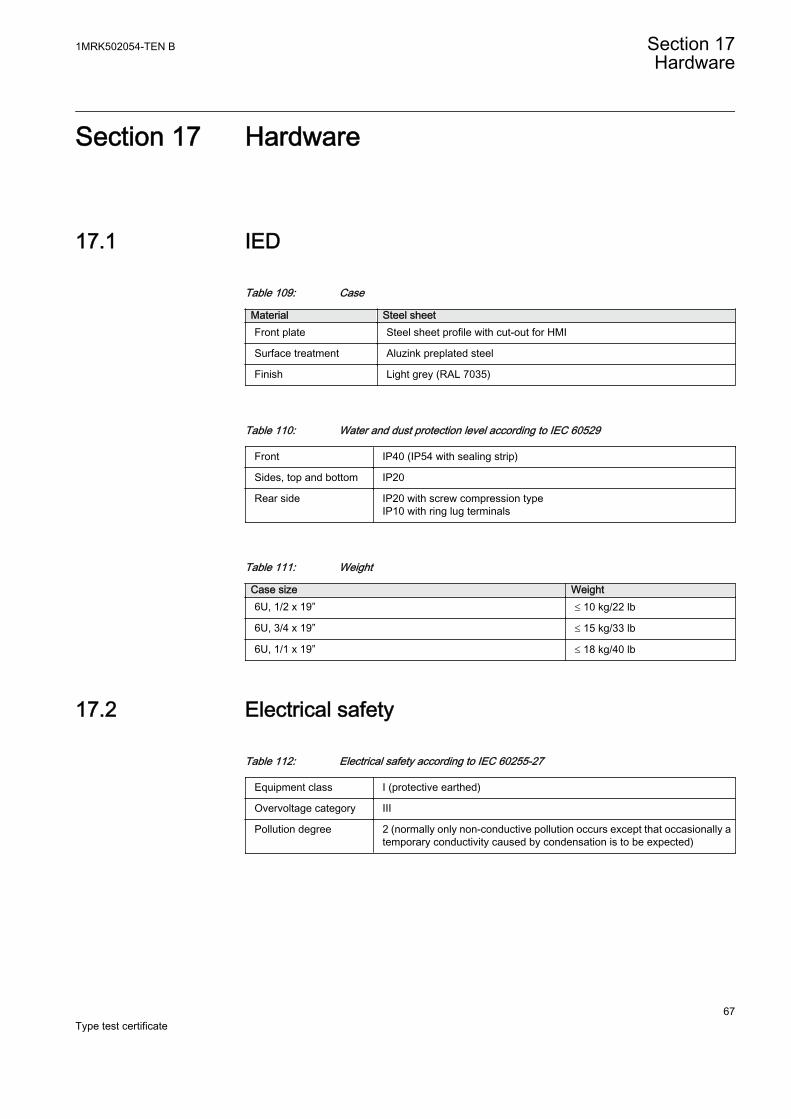
Section 17 Hardware
17.1 IED
Table 109: Case
Material Steel sheetFront plate Steel sheet profile with cut-out for HMI
Surface treatment Aluzink preplated steel
Finish Light grey (RAL 7035)
Table 110: Water and dust protection level according to IEC 60529
Front IP40 (IP54 with sealing strip)
Sides, top and bottom IP20
Rear side IP20 with screw compression typeIP10 with ring lug terminals
Table 111: Weight
Case size Weight6U, 1/2 x 19” £ 10 kg/22 lb
6U, 3/4 x 19” £ 15 kg/33 lb
6U, 1/1 x 19” £ 18 kg/40 lb
17.2 Electrical safety
Table 112: Electrical safety according to IEC 60255-27
Equipment class I (protective earthed)
Overvoltage category III
Pollution degree 2 (normally only non-conductive pollution occurs except that occasionally atemporary conductivity caused by condensation is to be expected)
1MRK502054-TEN B Section 17Hardware
67Type test certificate
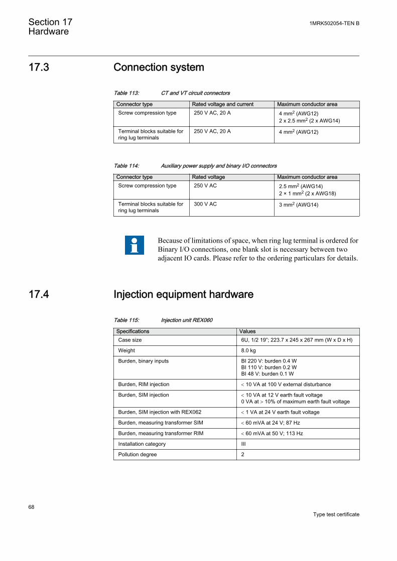
17.3 Connection system
Table 113: CT and VT circuit connectors
Connector type Rated voltage and current Maximum conductor areaScrew compression type 250 V AC, 20 A 4 mm2 (AWG12)
2 x 2.5 mm2 (2 x AWG14)
Terminal blocks suitable forring lug terminals
250 V AC, 20 A 4 mm2 (AWG12)
Table 114: Auxiliary power supply and binary I/O connectors
Connector type Rated voltage Maximum conductor areaScrew compression type 250 V AC 2.5 mm2 (AWG14)
2 × 1 mm2 (2 x AWG18)
Terminal blocks suitable forring lug terminals
300 V AC 3 mm2 (AWG14)
Because of limitations of space, when ring lug terminal is ordered forBinary I/O connections, one blank slot is necessary between twoadjacent IO cards. Please refer to the ordering particulars for details.
17.4 Injection equipment hardware
Table 115: Injection unit REX060
Specifications ValuesCase size 6U, 1/2 19”; 223.7 x 245 x 267 mm (W x D x H)
Weight 8.0 kg
Burden, binary inputs BI 220 V: burden 0.4 WBI 110 V: burden 0.2 WBI 48 V: burden 0.1 W
Burden, RIM injection < 10 VA at 100 V external disturbance
Burden, SIM injection < 10 VA at 12 V earth fault voltage0 VA at > 10% of maximum earth fault voltage
Burden, SIM injection with REX062 < 1 VA at 24 V earth fault voltage
Burden, measuring transformer SIM < 60 mVA at 24 V; 87 Hz
Burden, measuring transformer RIM < 60 mVA at 50 V; 113 Hz
Installation category III
Pollution degree 2
Section 17 1MRK502054-TEN BHardware
68Type test certificate
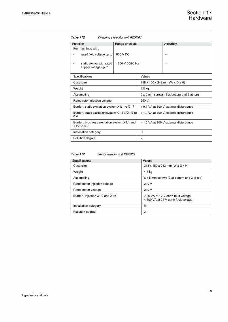
Table 116: Coupling capacitor unit REX061
Function Range or values AccuracyFor machines with:
• rated field voltage up to 800 V DC -
• static exciter with ratedsupply voltage up to
1600 V 50/60 Hz -
Specifications Values
Case size 218 x 150 x 243 mm (W x D x H)
Weight 4.8 kg
Assembling 6 x 5 mm screws (3 at bottom and 3 at top)
Rated rotor injection voltage 250 V
Burden, static excitation system X1:1 to X1:7 < 0.5 VA at 100 V external disturbance
Burden, static excitation system X1:1 or X1:7 to0 V
< 1.0 VA at 100 V external disturbance
Burden, brushless excitation system X1:1 andX1:7 to 0 V
< 1.5 VA at 100 V external disturbance
Installation category III
Pollution degree 2
Table 117: Shunt resistor unit REX062
Specifications ValuesCase size 218 x 150 x 243 mm (W x D x H)
Weight 4.5 kg
Assembling 6 x 5 mm screws (3 at bottom and 3 at top)
Rated stator injection voltage 240 V
Rated stator voltage 240 V
Burden, injection X1:2 and X1:4 < 25 VA at 12 V earth fault voltage< 100 VA at 24 V earth fault voltage
Installation category III
Pollution degree 2
1MRK502054-TEN B Section 17Hardware
69Type test certificate

70
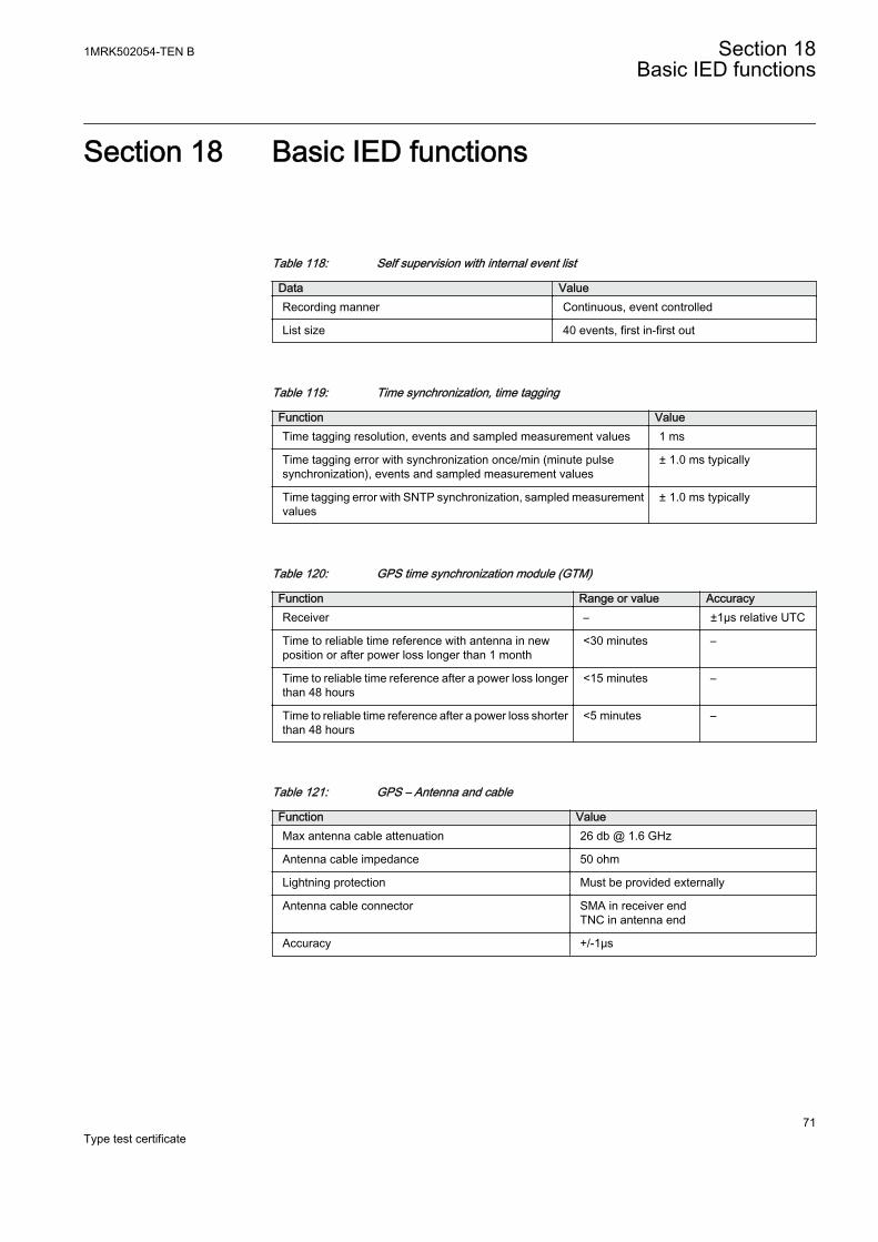
Section 18 Basic IED functions
Table 118: Self supervision with internal event list
Data ValueRecording manner Continuous, event controlled
List size 40 events, first in-first out
Table 119: Time synchronization, time tagging
Function ValueTime tagging resolution, events and sampled measurement values 1 ms
Time tagging error with synchronization once/min (minute pulsesynchronization), events and sampled measurement values
± 1.0 ms typically
Time tagging error with SNTP synchronization, sampled measurementvalues
± 1.0 ms typically
Table 120: GPS time synchronization module (GTM)
Function Range or value AccuracyReceiver – ±1µs relative UTC
Time to reliable time reference with antenna in newposition or after power loss longer than 1 month
<30 minutes –
Time to reliable time reference after a power loss longerthan 48 hours
<15 minutes –
Time to reliable time reference after a power loss shorterthan 48 hours
<5 minutes –
Table 121: GPS – Antenna and cable
Function ValueMax antenna cable attenuation 26 db @ 1.6 GHz
Antenna cable impedance 50 ohm
Lightning protection Must be provided externally
Antenna cable connector SMA in receiver endTNC in antenna end
Accuracy +/-1μs
1MRK502054-TEN B Section 18Basic IED functions
71Type test certificate
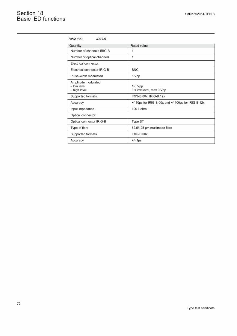
Table 122: IRIG-B
Quantity Rated valueNumber of channels IRIG-B 1
Number of optical channels 1
Electrical connector:
Electrical connector IRIG-B BNC
Pulse-width modulated 5 Vpp
Amplitude modulated– low level– high level
1-3 Vpp3 x low level, max 9 Vpp
Supported formats IRIG-B 00x, IRIG-B 12x
Accuracy +/-10μs for IRIG-B 00x and +/-100μs for IRIG-B 12x
Input impedance 100 k ohm
Optical connector:
Optical connector IRIG-B Type ST
Type of fibre 62.5/125 μm multimode fibre
Supported formats IRIG-B 00x
Accuracy +/- 1μs
Section 18 1MRK502054-TEN BBasic IED functions
72Type test certificate
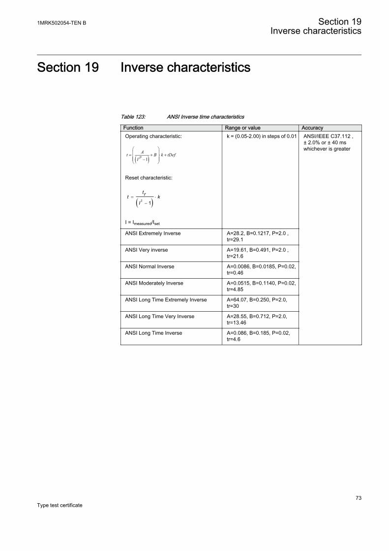
Section 19 Inverse characteristics
Table 123: ANSI Inverse time characteristics
Function Range or value AccuracyOperating characteristic:
( )1PAt B k tDef
I
æ öç ÷= + × +ç ÷ç - ÷è ø
EQUATION1249-SMALL V2 EN
Reset characteristic:
( )2 1= ×
-
trt kI
EQUATION1250-SMALL V1 EN
I = Imeasured/Iset
k = (0.05-2.00) in steps of 0.01 ANSI/IEEE C37.112 ,± 2.0% or ± 40 mswhichever is greater
ANSI Extremely Inverse A=28.2, B=0.1217, P=2.0 ,tr=29.1
ANSI Very inverse A=19.61, B=0.491, P=2.0 ,tr=21.6
ANSI Normal Inverse A=0.0086, B=0.0185, P=0.02,tr=0.46
ANSI Moderately Inverse A=0.0515, B=0.1140, P=0.02,tr=4.85
ANSI Long Time Extremely Inverse A=64.07, B=0.250, P=2.0,tr=30
ANSI Long Time Very Inverse A=28.55, B=0.712, P=2.0,tr=13.46
ANSI Long Time Inverse A=0.086, B=0.185, P=0.02,tr=4.6
1MRK502054-TEN B Section 19Inverse characteristics
73Type test certificate
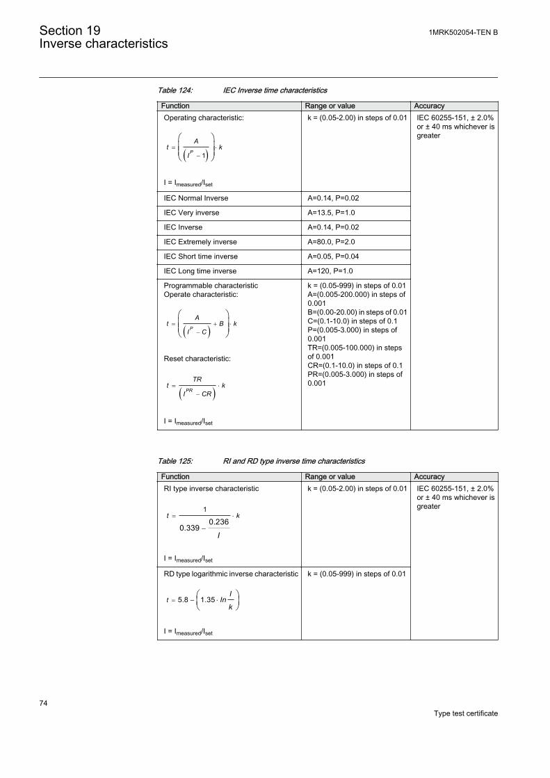
Table 124: IEC Inverse time characteristics
Function Range or value AccuracyOperating characteristic:
( )1= ×
-
æ öç ÷ç ÷è ø
P
At k
I
EQUATION1251-SMALL V1 EN
I = Imeasured/Iset
k = (0.05-2.00) in steps of 0.01 IEC 60255-151, ± 2.0%or ± 40 ms whichever isgreater
IEC Normal Inverse A=0.14, P=0.02
IEC Very inverse A=13.5, P=1.0
IEC Inverse A=0.14, P=0.02
IEC Extremely inverse A=80.0, P=2.0
IEC Short time inverse A=0.05, P=0.04
IEC Long time inverse A=120, P=1.0
Programmable characteristicOperate characteristic:
( )= + ×
-
æ öç ÷ç ÷è ø
P
At B k
I C
EQUATION1370-SMALL V1 EN
Reset characteristic:
( )= ×
-PR
TRt k
I CR
EQUATION1253-SMALL V1 EN
I = Imeasured/Iset
k = (0.05-999) in steps of 0.01A=(0.005-200.000) in steps of0.001B=(0.00-20.00) in steps of 0.01C=(0.1-10.0) in steps of 0.1P=(0.005-3.000) in steps of0.001TR=(0.005-100.000) in stepsof 0.001CR=(0.1-10.0) in steps of 0.1PR=(0.005-3.000) in steps of0.001
Table 125: RI and RD type inverse time characteristics
Function Range or value AccuracyRI type inverse characteristic
1
0.2360.339
= ×
-
t k
IEQUATION1137-SMALL V1 EN
I = Imeasured/Iset
k = (0.05-2.00) in steps of 0.01 IEC 60255-151, ± 2.0%or ± 40 ms whichever isgreater
RD type logarithmic inverse characteristic
5.8 1.35= - ×æ öç ÷è ø
tI
Ink
EQUATION1138-SMALL V1 EN
I = Imeasured/Iset
k = (0.05-999) in steps of 0.01
Section 19 1MRK502054-TEN BInverse characteristics
74Type test certificate
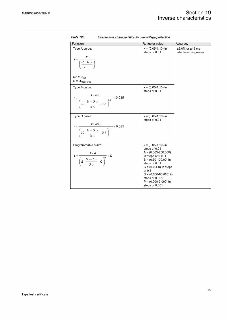
Table 126: Inverse time characteristics for overvoltage protection
Function Range or value AccuracyType A curve:
=- >
>
æ öç ÷è ø
tk
U U
UEQUATION1436-SMALL V1 EN
U> = UsetU = Umeasured
k = (0.05-1.10) insteps of 0.01
±5.0% or ±45 mswhichever is greater
Type B curve:
2.0
480
32 0.5
=⋅
− >⋅ −
0.035+
>
tk
U U
UEQUATION1437-SMALL V2 EN
k = (0.05-1.10) insteps of 0.01
Type C curve:
3.0
480
32 0.5
=⋅
⋅ −− >
0.035+
>
tk
U U
UEQUATION1438-SMALL V2 EN
k = (0.05-1.10) insteps of 0.01
Programmable curve:
×= +
- >× -
>
æ öç ÷è ø
P
k At D
U UB C
UEQUATION1439-SMALL V1 EN
k = (0.05-1.10) insteps of 0.01A = (0.005-200.000)in steps of 0.001B = (0.50-100.00) insteps of 0.01C = (0.0-1.0) in stepsof 0.1D = (0.000-60.000) insteps of 0.001P = (0.000-3.000) insteps of 0.001
1MRK502054-TEN B Section 19Inverse characteristics
75Type test certificate
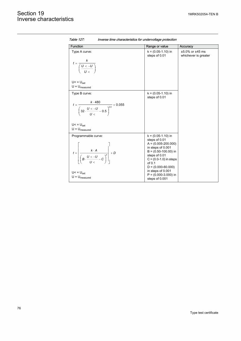
Table 127: Inverse time characteristics for undervoltage protection
Function Range or value AccuracyType A curve:
=< -
<
æ öç ÷è ø
kt
U U
UEQUATION1431-SMALL V1 EN
U< = UsetU = Umeasured
k = (0.05-1.10) insteps of 0.01
±5.0% or ±45 mswhichever is greater
Type B curve:
2.0
4800.055
32 0.5
×= +
< -× -
<
æ öç ÷è ø
kt
U U
UEQUATION1432-SMALL V1 EN
U< = UsetU = Umeasured
k = (0.05-1.10) insteps of 0.01
Programmable curve:
×= +
< -× -
<
é ùê úê úê úæ öê úç ÷ë è ø û
P
k At D
U UB C
UEQUATION1433-SMALL V1 EN
U< = UsetU = Umeasured
k = (0.05-1.10) insteps of 0.01A = (0.005-200.000)in steps of 0.001B = (0.50-100.00) insteps of 0.01C = (0.0-1.0) in stepsof 0.1D = (0.000-60.000)in steps of 0.001P = (0.000-3.000) insteps of 0.001
Section 19 1MRK502054-TEN BInverse characteristics
76Type test certificate

Table 128: Inverse time characteristics for residual overvoltage protection
Function Range or value AccuracyType A curve:
=- >
>
æ öç ÷è ø
tk
U U
UEQUATION1436-SMALL V1 EN
U> = UsetU = Umeasured
k = (0.05-1.10) in steps of0.01
±5.0% or ±45 mswhichever isgreater
Type B curve:
2.0
480
32 0.5
=⋅
− >⋅ −
0.035+
>
tk
U U
UEQUATION1437-SMALL V2 EN
k = (0.05-1.10) in steps of0.01
Type C curve:
3.0
480
32 0.5
=⋅
⋅ −− >
0.035+
>
tk
U U
UEQUATION1438-SMALL V2 EN
k = (0.05-1.10) in steps of0.01
Programmable curve:
×= +
- >× -
>
æ öç ÷è ø
P
k At D
U UB C
UEQUATION1439-SMALL V1 EN
k = (0.05-1.10) in steps of0.01A = (0.005-200.000) insteps of 0.001B = (0.50-100.00) in stepsof 0.01C = (0.0-1.0) in steps of0.1D = (0.000-60.000) insteps of 0.001P = (0.000-3.000) in stepsof 0.001
1MRK502054-TEN B Section 19Inverse characteristics
77Type test certificate
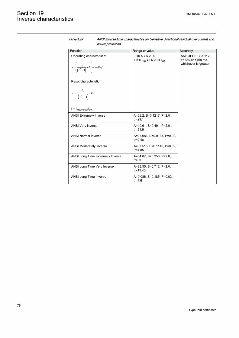
Table 129: ANSI Inverse time characteristics for Sensitive directional residual overcurrent andpower protection
Function Range or value AccuracyOperating characteristic:
( )1PAt B k tDef
I
æ öç ÷= + × +ç ÷ç - ÷è ø
EQUATION1249-SMALL V2 EN
Reset characteristic:
( )2 1= ×
-
trt kI
EQUATION1250-SMALL V1 EN
I = Imeasured/Iset
0.10 ≤ k ≤ 2.001.5 x Iset ≤ I ≤ 20 x Iset
ANSI/IEEE C37.112 ,±5.0% or ±160 mswhichever is greater
ANSI Extremely Inverse A=28.2, B=0.1217, P=2.0 ,tr=29.1
ANSI Very inverse A=19.61, B=0.491, P=2.0 ,tr=21.6
ANSI Normal Inverse A=0.0086, B=0.0185, P=0.02,tr=0.46
ANSI Moderately Inverse A=0.0515, B=0.1140, P=0.02,tr=4.85
ANSI Long Time Extremely Inverse A=64.07, B=0.250, P=2.0,tr=30
ANSI Long Time Very Inverse A=28.55, B=0.712, P=2.0,tr=13.46
ANSI Long Time Inverse A=0.086, B=0.185, P=0.02,tr=4.6
Section 19 1MRK502054-TEN BInverse characteristics
78Type test certificate
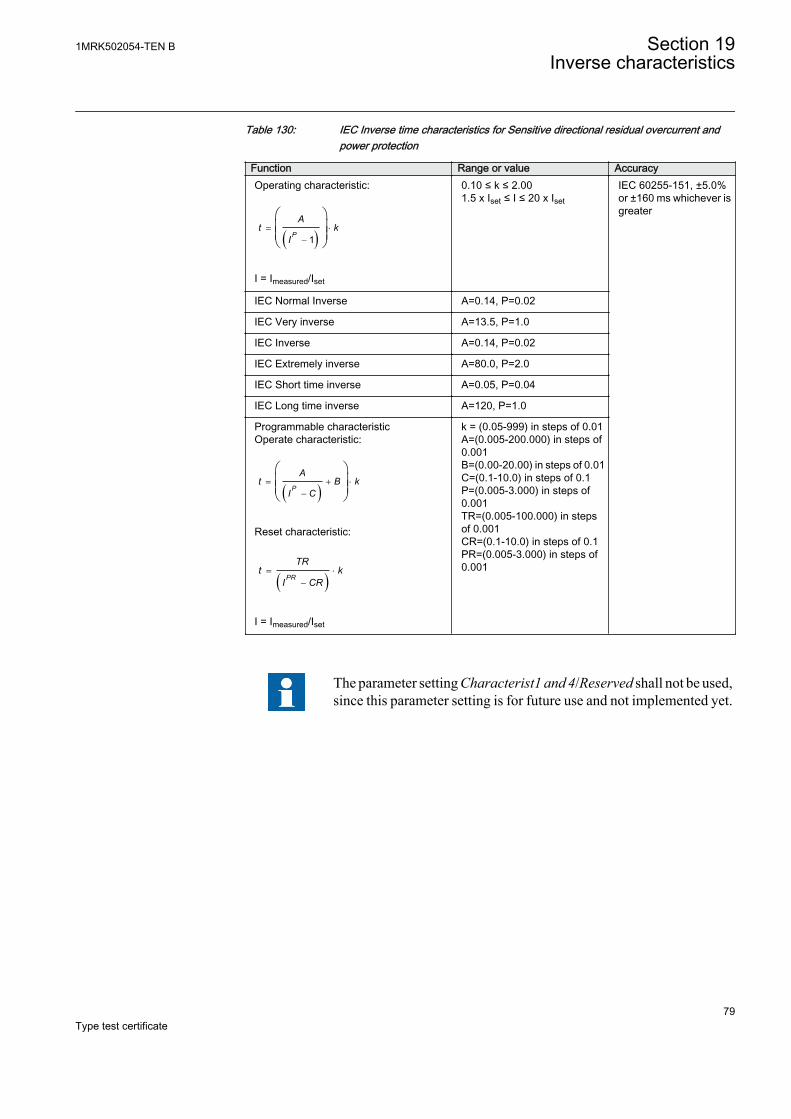
Table 130: IEC Inverse time characteristics for Sensitive directional residual overcurrent andpower protection
Function Range or value AccuracyOperating characteristic:
( )1= ×
-
æ öç ÷ç ÷è ø
P
At k
I
EQUATION1251-SMALL V1 EN
I = Imeasured/Iset
0.10 ≤ k ≤ 2.001.5 x Iset ≤ I ≤ 20 x Iset
IEC 60255-151, ±5.0%or ±160 ms whichever isgreater
IEC Normal Inverse A=0.14, P=0.02
IEC Very inverse A=13.5, P=1.0
IEC Inverse A=0.14, P=0.02
IEC Extremely inverse A=80.0, P=2.0
IEC Short time inverse A=0.05, P=0.04
IEC Long time inverse A=120, P=1.0
Programmable characteristicOperate characteristic:
( )= + ×
-
æ öç ÷ç ÷è ø
P
At B k
I C
EQUATION1370-SMALL V1 EN
Reset characteristic:
( )= ×
-PR
TRt k
I CR
EQUATION1253-SMALL V1 EN
I = Imeasured/Iset
k = (0.05-999) in steps of 0.01A=(0.005-200.000) in steps of0.001B=(0.00-20.00) in steps of 0.01C=(0.1-10.0) in steps of 0.1P=(0.005-3.000) in steps of0.001TR=(0.005-100.000) in stepsof 0.001CR=(0.1-10.0) in steps of 0.1PR=(0.005-3.000) in steps of0.001
The parameter setting Characterist1 and 4/Reserved shall not be used,since this parameter setting is for future use and not implemented yet.
1MRK502054-TEN B Section 19Inverse characteristics
79Type test certificate
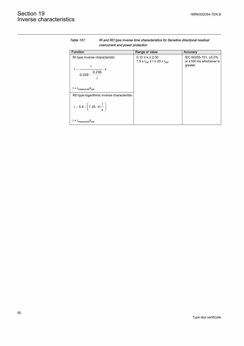
Table 131: RI and RD type inverse time characteristics for Sensitive directional residualovercurrent and power protection
Function Range or value AccuracyRI type inverse characteristic
1
0.2360.339
= ×
-
t k
IEQUATION1137-SMALL V1 EN
I = Imeasured/Iset
0.10 ≤ k ≤ 2.001.5 x Iset ≤ I ≤ 20 x Iset
IEC 60255-151, ±5.0%or ±160 ms whichever isgreater
RD type logarithmic inverse characteristic
5.8 1.35= - ×æ öç ÷è ø
tI
Ink
EQUATION1138-SMALL V1 EN
I = Imeasured/Iset
Section 19 1MRK502054-TEN BInverse characteristics
80Type test certificate

81
Contact us
For more information please contact:
ABB ABSubstation Automation ProductsSE-721 59 Västerås, SwedenPhone +46 (0) 21 32 50 00
www.abb.com/substationautomation
Note:We reserve the right to make technical changes or modifythe contents of this document without prior notice. ABB ABdoes not accept any responsibility whatsoever for potentialerrors or possible lack of information in this document.We reserve all rights in this document and in the subjectmatter and illustrations contained herein. Any reproduction,disclosure to third parties or utilization of its contents – inwhole or in part – is forbidden without prior written consent ofABB AB.
© Copyright 2014 ABB.
All rights reserved.
Scan this QR code to visit our website
1MR
K50
2054
-TE
N