Embed Size (px)
Citation preview
Type SMP ConnectorsProduct Catalog

© 2014 Bel Fuse, Inc. doc rev number
Cinch Connectivity Solutions
299 Johnson Avenue SW, Suite 100
Waseca, MN 56093 USA
+1 507.833.8822
cinchconnectivity.com

TABLE OF CONTENTS
Introduction 1-2
Specifications 3-8
Mounting Holes 7
Applications 9-12
Assembly Tools 13
Assembly Instructions 14-18
Competitor Cross Reference 19
1
SMP Blind-Mate Connectors
INTRODUCTION
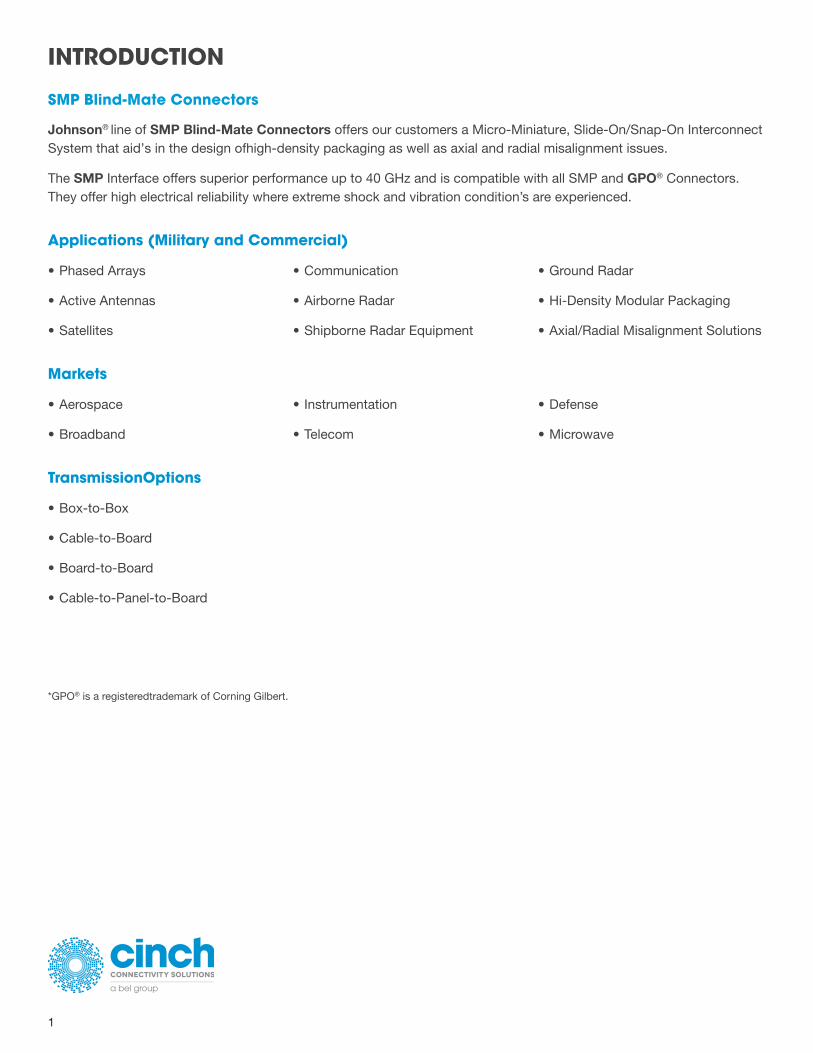
Johnson® line of SMP Blind-Mate Connectors offers our customers a Micro-Miniature, Slide-On/Snap-On Interconnect System that aid’s in the design ofhigh-density packaging as well as axial and radial misalignment issues.
The SMP Interface offers superior performance up to 40 GHz and is compatible with all SMP and GPO® Connectors. They offer high electrical reliability where extreme shock and vibration condition’s are experienced.
Applications (Military and Commercial)
• Phased Arrays
• Active Antennas
• Satellites
• Communication
• Airborne Radar
• Shipborne Radar Equipment
• Ground Radar
• Hi-Density Modular Packaging
• Axial/Radial Misalignment Solutions
Markets
• Aerospace
• Broadband
• Instrumentation
• Telecom
• Defense
• Microwave
TransmissionOptions
• Box-to-Box
• Cable-to-Board
• Board-to-Board
• Cable-to-Panel-to-Board
*GPO® is a registeredtrademark of Corning Gilbert.
+1 507.833.8822
cinchconnectivity.com
2
INTRODUCTION
Description
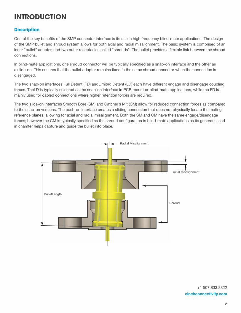
One of the key benefits of the SMP connector interface is its use in high frequency blind-mate applications. The design of the SMP bullet and shroud system allows for both axial and radial misalignment. The basic system is comprised of an inner “bullet” adapter, and two outer receptacles called “shrouds”. The bullet provides a flexible link between the shroud connections.
In blind-mate applications, one shroud connector will be typically specified as a snap-on interface and the other as a slide-on. This ensures that the bullet adapter remains fixed in the same shroud connector when the connection is disengaged.
The two snap-on interfaces Full Detent (FD) andLimited Detent (LD) each have different engage and disengage coupling forces. TheLD is typically selected as the snap-on interface in PCB mount or blind-mate applications, while the FD is mainly used for cabled connections where higher retention forces are required.
The two slide-on interfaces Smooth Bore (SM) and Catcher’s Mit (CM) allow for reduced connection forces as compared to the snap-on versions. The push-on interface creates a sliding connection that does not physically locate the mating reference planes, allowing for axial and radial misalignment. Both the SM and CM have the same engage/disengage forces; however the CM is typically specified as the shroud configuration in blind-mate applications as its generous lead-in chamfer helps capture and guide the bullet into place.
BulletLength
Radial Misalignment
Axial Misalignment
Shroud
3
ELECTRICAL SPECIFICATIONS
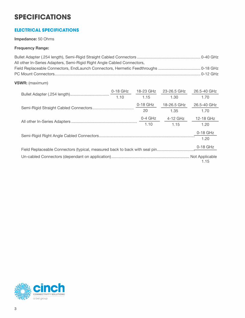
Impedance: 50 Ohms
Frequency Range:
Bullet Adapter (.254 length), Semi-Rigid Straight Cabled Connectors ......................................................... 0-40 GHz All other In-Series Adapters, Semi-Rigid Right Angle Cabled Connectors, Field Replaceable Connectors, EndLaunch Connectors, Hermetic Feedthroughs ...................................... 0-18 GHz PC Mount Connectors ................................................................................................................................... 0-12 GHz
VSWR: (maximum)
SPECIFICATIONS
Bullet Adapter (.254 length) ...................................0-18 GHz
1.10
18-23 GHz
1.15
23-26.5 GHz
1.30
26.5-40 GHz
1.70
Semi-Rigid Straight Cabled Connectors .....................................0-18 GHz
2018-26.5 GHz
1.35
26.5-40 GHz
1.70
All other In-Series Adapters ...........................................................0-4 GHz
1.104-12 GHz
1.15
12-18 GHz
1.20
1.15
Semi-Rigid Right Angle Cabled Connectors ......................................................................................0-18 GHz
1.20
Field Replaceable Connectors (typical, measured back to back with seal pin ..................................0-18 GHz
Un-cabled Connectors (dependant on application) ...................................................................... Not Applicable

+1 507.833.8822
cinchconnectivity.com
4
Insertion Loss: (dB maximum, tested at 10 GHz) In-Series Adapters, Field Replaceable Connectors .........................................................................0.10 √ F (GHz) Semi-Rigid Cabled Connectors .......................................................................................................0.12 √ F (GHz) All other Un-cabled Connector ....................................................................................................... Not Applicable
Working Voltage: 335 Vrms maximum at sea level, 65 Vrms maximum at 70,000 feet Dielectric Withstanding: Voltage: 500 Vrms minimum at sea level RF High Potential Withstanding Voltage: 325 Vrms minimum at sea level, tested at 4 and 7 MHz Corona Level: 190 Vrms minimum at 70,000 feet
Contact Resistance: (milliohms maximum initial, not applicable after environmental testing) Center Contact (Connectors and Adapters) .........................................................................................................6.0 Outer Contact (Connectors and Adapters) ..........................................................................................................2.0 Cable Shield to Body (Semi-Rigid Cabled Connectors Only) ..............................................................................0.5
Insulation Resistance: 5000 megohms minimum
RF Leakage: (dB typical, tested at 2.5 GHz) Cabled and Field Replaceable Connectors ........................................................................................................ -80 In-Series Adapters............................................................................................................................................... -65 All other Un-cabled Connectors ........................................................................................................Not Applicable
5
MECHANICAL SPECIFICATIONS
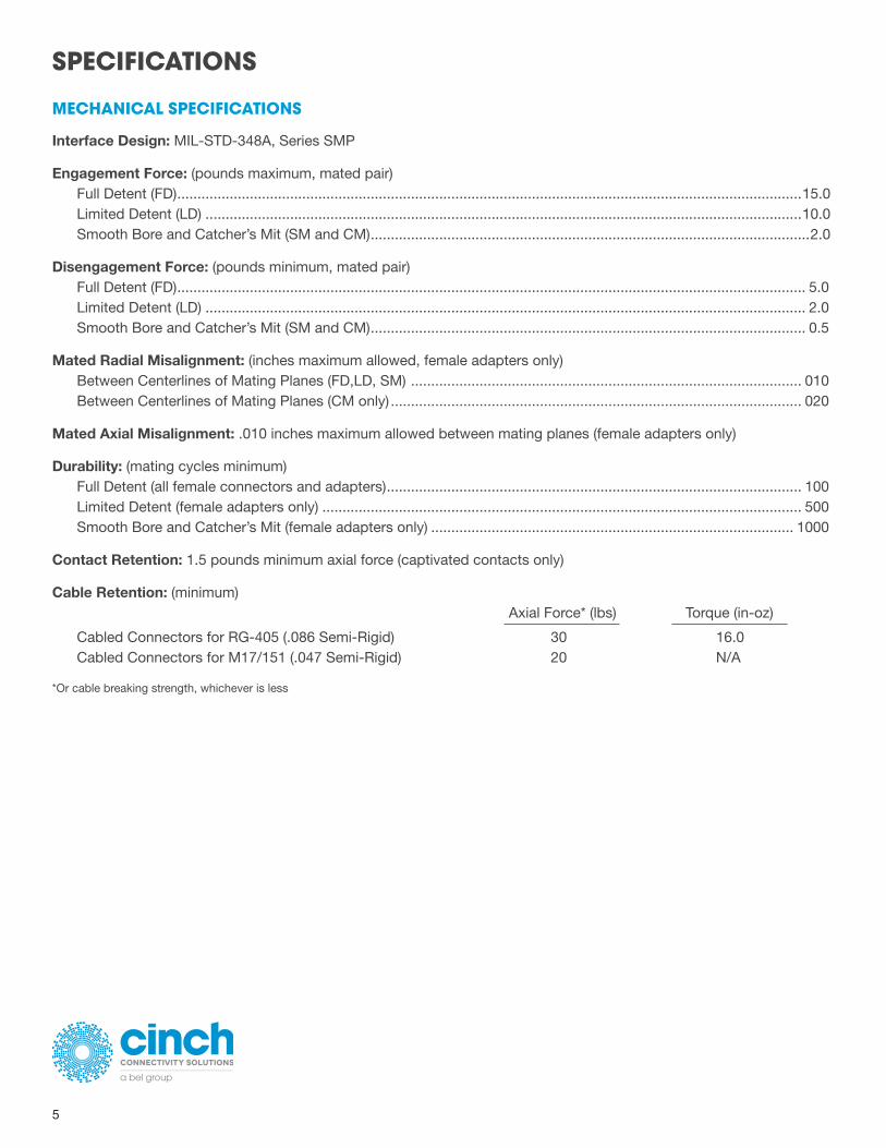
Interface Design: MIL-STD-348A, Series SMP
Engagement Force: (pounds maximum, mated pair) Full Detent (FD) ...........................................................................................................................................................15.0 Limited Detent (LD) ....................................................................................................................................................10.0 Smooth Bore and Catcher’s Mit (SM and CM) .............................................................................................................2.0
Disengagement Force: (pounds minimum, mated pair) Full Detent (FD) ............................................................................................................................................................ 5.0 Limited Detent (LD) ..................................................................................................................................................... 2.0 Smooth Bore and Catcher’s Mit (SM and CM) ............................................................................................................ 0.5
Mated Radial Misalignment: (inches maximum allowed, female adapters only)Between Centerlines of Mating Planes (FD,LD, SM) ................................................................................................. 010 Between Centerlines of Mating Planes (CM only) ...................................................................................................... 020
Mated Axial Misalignment: .010 inches maximum allowed between mating planes (female adapters only)
Durability: (mating cycles minimum) Full Detent (all female connectors and adapters) ....................................................................................................... 100 Limited Detent (female adapters only) ....................................................................................................................... 500 Smooth Bore and Catcher’s Mit (female adapters only) .......................................................................................... 1000
Contact Retention: 1.5 pounds minimum axial force (captivated contacts only)
Cable Retention: (minimum) Axial Force* (lbs) Torque (in-oz)
Cabled Connectors for RG-405 (.086 Semi-Rigid) 30 16.0 Cabled Connectors for M17/151 (.047 Semi-Rigid) 20 N/A
*Or cable breaking strength, whichever is less
SPECIFICATIONS
+1 507.833.8822
cinchconnectivity.com
6
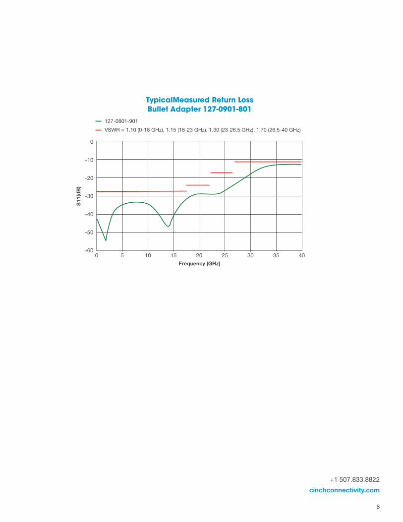
127-0801-901
VSWR = 1.10 (0-18 GHz), 1.15 (18-23 GHz), 1.30 (23-26.5 GHz), 1.70 (26.5-40 GHz)
6
Connectivity for
Business-Critical ContinuitySMP ConnectorsSpecifications
MECHANICAL SPECIFICATIONSInterface Design: MIL-STD-348A, Series SMP
Engagement Force: (poundsmaximum,mated pair)Full Detent (FD) . . . . . . . . . . . . . . . . . . . . . . . . . . . . . . . . . . . . . . . . . . . . . . . . . . . . . . . . . . . . . . . . . . . . . . . . . . . . . . . . . . . . . . . . . 15.0Limited Detent (LD) . . . . . . . . . . . . . . . . . . . . . . . . . . . . . . . . . . . . . . . . . . . . . . . . . . . . . . . . . . . . . . . . . . . . . . . . . . . . . . . . . . . . . 10.0Smooth Bore and Catcher’s Mit (SM and CM) . . . . . . . . . . . . . . . . . . . . . . . . . . . . . . . . . . . . . . . . . . . . . . . . . . . . . . . . . . . . . . . 2.0
Disengagement Force: (poundsminimum,mated pair)Full Detent (FD) . . . . . . . . . . . . . . . . . . . . . . . . . . . . . . . . . . . . . . . . . . . . . . . . . . . . . . . . . . . . . . . . . . . . . . . . . . . . . . . . . . . . . . . . . . 5.0Limited Detent (LD) . . . . . . . . . . . . . . . . . . . . . . . . . . . . . . . . . . . . . . . . . . . . . . . . . . . . . . . . . . . . . . . . . . . . . . . . . . . . . . . . . . . . . . 2.0Smooth Bore and Catcher’s Mit (SM and CM) . . . . . . . . . . . . . . . . . . . . . . . . . . . . . . . . . . . . . . . . . . . . . . . . . . . . . . . . . . . . . . . . 0.5
Mated Radial Misalignment: (inchesmaximum allowed, female adapters only)Between Centerlines of Mating Planes (FD, LD, SM) . . . . . . . . . . . . . . . . . . . . . . . . . . . . . . . . . . . . . . . . . . . . . . . . . . . . . . . . . . .010Between Centerlines of Mating Planes (CM only) . . . . . . . . . . . . . . . . . . . . . . . . . . . . . . . . . . . . . . . . . . . . . . . . . . . . . . . . . . . . .020
Mated Axial Misalignment: .010 inchesmaximum allowed betweenmating planes (female adapters only)
Durability: (mating cycles minimum)Full Detent (all female connectors and adapters) . . . . . . . . . . . . . . . . . . . . . . . . . . . . . . . . . . . . . . . . . . . . . . . . . . . . . . . . . . . . 100Limited Detent (female adapters only) . . . . . . . . . . . . . . . . . . . . . . . . . . . . . . . . . . . . . . . . . . . . . . . . . . . . . . . . . . . . . . . . . . . . 500Smooth Bore and Catcher’s Mit (female adapters only) . . . . . . . . . . . . . . . . . . . . . . . . . . . . . . . . . . . . . . . . . . . . . . . . . . . . . . 1000
Contact Retention: 1.5 poundsminimum axial force (captivated contacts only)
Cable Retention: (minimum)Axial Force* (lbs) Torque (in-oz)
Cabled Connectors for RG-405 (.086 Semi-Rigid) . . . . . . . . . . . . . . . . . . . . . . . . . . . . . . . . . . . . . . . 30 16.0Cabled Connectors for M17/151 (.047 Semi-Rigid) . . . . . . . . . . . . . . . . . . . . . . . . . . . . . . . . . . . . . 20 N/A
*Or cable breaking strength, whichever is less
0 5 10 15 20 25 30 35 40
0
-10
-20
-30
-40
-50
-60
Frequency (GHz)
S11(dB)
Typical Measured Return LossBullet Adapter 127-0901-801
127-0801-901 VSWR = 1.10 (0-18 GHz), 1.15 (18-23 GHz), 1.30 (23-26.5 GHz), 1.70 (26.5-40 GHz)
0 2010
0
-60
-50
-40
-30
-20
-10
305 2515 35 40Frequency (GHz)
S11
(dB
)
TypicalMeasured Return Loss Bullet Adapter 127-0901-801
7
SPECIFICATIONS
ENVIRONMENTAL SPECIFICATIONS
Operating Temperature: -65°C to +165°C
Thermal Shock: MIL-STD-202, Method 107, Condition B (except high temp +165°C or max high temp of cable)
Corrosion: MIL-STD-202, Method 101, Condition B
Shock (specified pulse): MIL-STD-202, Method 213, Condition I
Vibration: MIL-STD-202, Method 204, Condition D
Moisture Resistance: MIL-STD-202, Method 106 (except step 7b omitted)
MATERIAL SPECIFICATIONS
Spring Finger (female) and End Launch (male) Bodies: Beryllium Copper per ASTM B196, Gold* plated per MIL-DTL-45204 (.00005” min)
Hermetic Seal Bodies (male): Kovar Alloy per ASTM F15, Gold* plated per MIL-DTL-45204 (.00005” min)
All other Shroud Bodies (male): Stainless Steel, Type 303, per ASTM A582, Passivated per MIL-DTL-14072 (EL 300)
Connector and Adapter Contacts (male and female): Beryllium Copper per ASTM B196, Gold* plated per MIL-DTL-45204 (.00005” min)
Hermetic Seal Center Pins: Kovar Alloy per ASTM F15, Gold* plated per MIL-DTL-45204 (.00005” min)
EMI/Anti-Rock Rings: Beryllium Copper per ASTM B196, Gold* plated per MIL-DTL-45204 (.00003” min)
PC Mount Legs: Brass per ASTM B16, Gold* plated per MIL-DTL-45204 (.00003” min)
Connector and Adapter Insulators: PTFE per ASTM D1710
Hermetic Seal Glass: Corning 7070
*All gold plated parts include a .00005” min nickel barrier layer.
(Meets or Exceeds the Applicable Paragraph of MIL-PRF-39012)
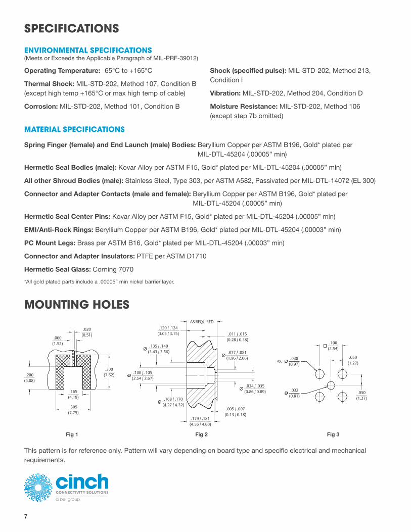
MOUNTING HOLES
This pattern is for reference only. Pattern will vary depending on board type and specific electrical and mechanical requirements.
Fig 1 Fig 3Fig 2
+1 507.833.8822
cinchconnectivity.com
8
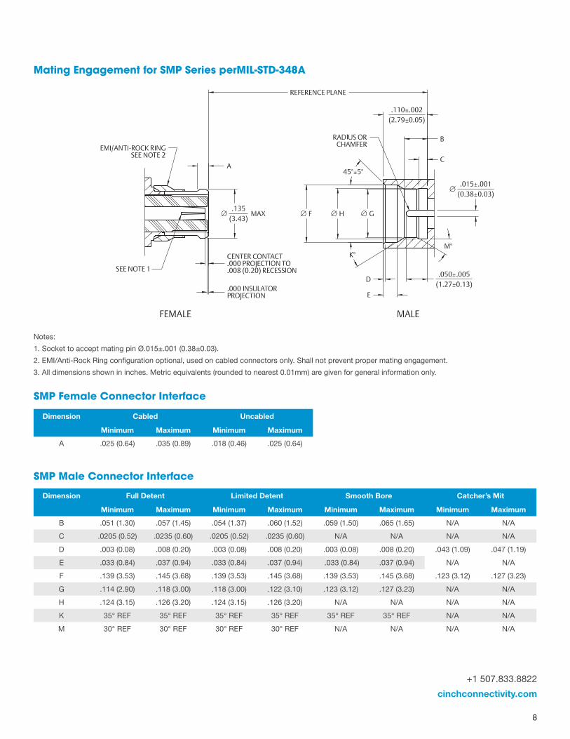
Mating Engagement for SMP Series perMIL-STD-348A
Notes:
1. Socket to accept mating pin Ø.015±.001 (0.38±0.03).
2. EMI/Anti-Rock Ring configuration optional, used on cabled connectors only. Shall not prevent proper mating engagement.
3. All dimensions shown in inches. Metric equivalents (rounded to nearest 0.01mm) are given for general information only.
SMP Male Connector Interface
Dimension Full Detent Limited Detent Smooth Bore Catcher’s Mit
Minimum Maximum Minimum Maximum Minimum Maximum Minimum Maximum
B .051 (1.30) .057 (1.45) .054 (1.37) .060 (1.52) .059 (1.50) .065 (1.65) N/A N/A
C .0205 (0.52) .0235 (0.60) .0205 (0.52) .0235 (0.60) N/A N/A N/A N/A
D .003 (0.08) .008 (0.20) .003 (0.08) .008 (0.20) .003 (0.08) .008 (0.20) .043 (1.09) .047 (1.19)
E .033 (0.84) .037 (0.94) .033 (0.84) .037 (0.94) .033 (0.84) .037 (0.94) N/A N/A
F .139 (3.53) .145 (3.68) .139 (3.53) .145 (3.68) .139 (3.53) .145 (3.68) .123 (3.12) .127 (3.23)
G .114 (2.90) .118 (3.00) .118 (3.00) .122 (3.10) .123 (3.12) .127 (3.23) N/A N/A
H .124 (3.15) .126 (3.20) .124 (3.15) .126 (3.20) N/A N/A N/A N/A
K 35° REF 35° REF 35° REF 35° REF 35° REF 35° REF N/A N/A
M 30° REF 30° REF 30° REF 30° REF N/A N/A N/A N/A
SMP Female Connector Interface
Dimension Cabled Uncabled
Minimum Maximum Minimum Maximum
A .025 (0.64) .035 (0.89) .018 (0.46) .025 (0.64)
9
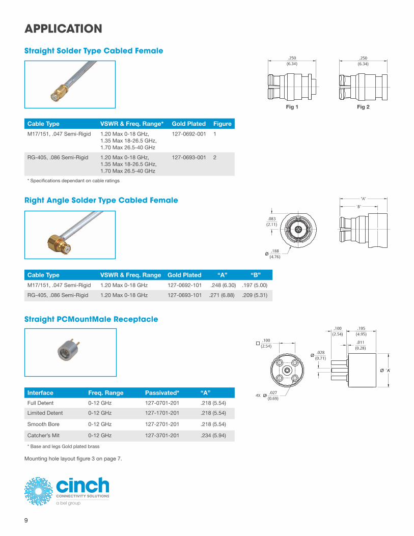
Straight Solder Type Cabled Female
Fig 1 Fig 2
Cable Type VSWR & Freq. Range* Gold Plated Figure
M17/151, .047 Semi-Rigid 1.20 Max 0-18 GHz, 1.35 Max 18-26.5 GHz, 1.70 Max 26.5-40 GHz
127-0692-001 1
RG-405, .086 Semi-Rigid 1.20 Max 0-18 GHz, 1.35 Max 18-26.5 GHz, 1.70 Max 26.5-40 GHz
127-0693-001 2
* Specifications dependant on cable ratings
Right Angle Solder Type Cabled Female
Cable Type VSWR & Freq. Range Gold Plated “A” “B”
M17/151, .047 Semi-Rigid 1.20 Max 0-18 GHz 127-0692-101 .248 (6.30) .197 (5.00)
RG-405, .086 Semi-Rigid 1.20 Max 0-18 GHz 127-0693-101 .271 (6.88) .209 (5.31)
Straight PCMountMale Receptacle
Interface Freq. Range Passivated* “A”
Full Detent 0-12 GHz 127-0701-201 .218 (5.54)
Limited Detent 0-12 GHz 127-1701-201 .218 (5.54)
Smooth Bore 0-12 GHz 127-2701-201 .218 (5.54)
Catcher’s Mit 0-12 GHz 127-3701-201 .234 (5.94)
* Base and legs Gold plated brass
Mounting hole layout figure 3 on page 7.
APPLICATION
+1 507.833.8822
cinchconnectivity.com
10
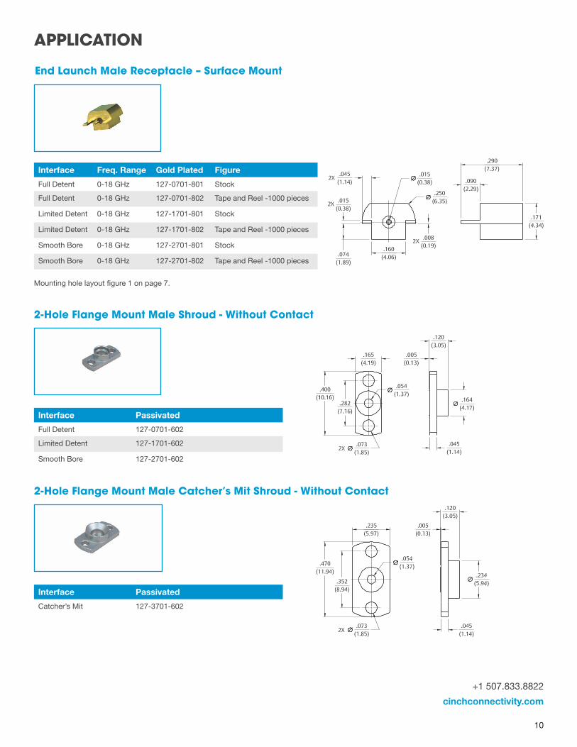
Interface Passivated
Full Detent 127-0701-602
Limited Detent 127-1701-602
Smooth Bore 127-2701-602
2-Hole Flange Mount Male Shroud - Without Contact
Interface Passivated
Catcher’s Mit 127-3701-602
2-Hole Flange Mount Male Catcher’s Mit Shroud - Without Contact
Interface Freq. Range Gold Plated Figure
Full Detent 0-18 GHz 127-0701-801 Stock
Full Detent 0-18 GHz 127-0701-802 Tape and Reel -1000 pieces
Limited Detent 0-18 GHz 127-1701-801 Stock
Limited Detent 0-18 GHz 127-1701-802 Tape and Reel -1000 pieces
Smooth Bore 0-18 GHz 127-2701-801 Stock
Smooth Bore 0-18 GHz 127-2701-802 Tape and Reel -1000 pieces
End Launch Male Receptacle – Surface Mount
Mounting hole layout figure 1 on page 7.
APPLICATION
11
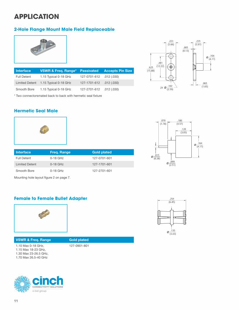
2-Hole Flange Mount Male Field Replaceable
Hermetic Seal Male
Female to Female Bullet Adapter
Interface VSWR & Freq. Range* Passivated Accepts Pin Size
Full Detent 1.15 Typical 0-18 GHz 127-0701-612 .012 (.030)
Limited Detent 1.15 Typical 0-18 GHz 127-1701-612 .012 (.030)
Smooth Bore 1.15 Typical 0-18 GHz 127-2701-612 .012 (.030)
VSWR & Freq. Range Gold plated
1.10 Max 0-18 GHz, 1.15 Max 18-23 GHz, 1.30 Max 23-26.5 GHz, 1.70 Max 26.5-40 GHz
127-0901-801
Interface Freq. Range Gold plated
Full Detent 0-18 GHz 127-0701-601
Limited Detent 0-18 GHz 127-1701-601
Smooth Bore 0-18 GHz 127-2701-601
* Two connectorsmated back to back with hermetic seal fixture
Mounting hole layout figure 2 on page 7.
APPLICATION
+1 507.833.8822
cinchconnectivity.com
12
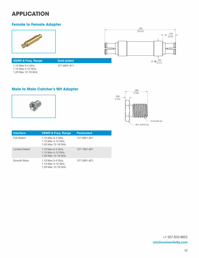
Female to Female Adapter
Male to Male Catcher’s Mit Adapter
VSWR & Freq. Range Gold plated
1.10 Max 0-4 GHz, 1.15 Max 4-12 GHz, 1.20 Max 12-18 GHz
127-0901-811
Interface VSWR & Freq. Range Passivated
Full Detent 1.10 Max 0-4 GHz, 1.15 Max 4-12 GHz, 1.20 Max 12-18 GHz
127-0901-821
Limited Detent 1.10 Max 0-4 GHz, 1.15 Max 4-12 GHz, 1.20 Max 12-18 GHz
127-1901-821
Smooth Bore 1.10 Max 0-4 GHz, 1.15 Max 4-12 GHz, 1.20 Max 12-18 GHz
127-2901-821
APPLICATION

13
C.
D.
A.
G.
H.
E.
F.
I. J.
B.
SMP Customer Tooling
Accurate assembly of the Semi-Rigid Cabled Connectors is obtained with the tools listed below. Industry standard devices are used if possiblefor customer convenience and tool compatibility.
Item Description Park Number
A SMP Bullet Extraction Tool 127-0000-900
B SMP Cabled Connector Removal Tool 127-0000-901
C Soldering Vise (does not include clamp inserts or stop screw) 140-0000-962
D Stop Screw for Soldering Vise 140-0000-981
E Semi-Rigid Cable Clamp Inserts for .086” OD Cable Semi-Rigid Cable Clamp Inserts for .047” OD Cable
140-0000-964 140-0000-997
F Solder Shim for .086” OD Cable 140-0000-984
G SMP Center Contact Holder 127-0000-902
H SMP Interface Locator Tool 127-0000-903
I SMP Right Angle Body Holder 127-0000-904
J SMP FD Shroud Centering Tool SMP LD Shroud Centering Tool SMP SB Shroud Centering Tool
127-0000-905 127-0000-906 127-0000-907
ASSEMBLY TOOLS
+1 507.833.8822
cinchconnectivity.com
14
ASSEMBLY INSTRUCTIONS
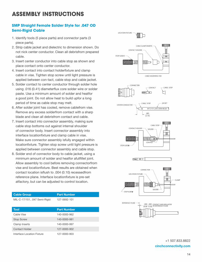
SMP Straight Female Solder Style for .047 OD Semi-Rigid Cable
1. Identify tools (5 piece parts) and connector parts (3piece parts).
2. Strip cable jacket and dielectric to dimension shown. Donot nick center conductor. Clean all debrisfrom preparedcable.
3. Insert center conductor into cable stop as shown andplace contact onto center conductor.
4. Insert contact into contact holderfixture and clampcable in vise. Tighten stop screw until light pressure isapplied between con-tact, cable stop and cable jacket.
5. Solder contact to center conductor through solder holeusing .016 (0.41) diameterflux core solder wire or solderpaste. Use a minimum amount of solder and heatfora good joint. Do not allow heat to build upfor a longperiod of time as cable stop may melt.
6. After solder joint has cooled, remove cablefrom vise.Remove any excess solderfrom contact with a sharpblade and clean all debrisfrom contact and cable.
7. Insert contact into connector assembly, making surecable stop bottoms out against internal shoulderof connector body. Insert connector assembly intointerface locationfixture and clamp cable in vise.Make sure connector assembly isfully engaged withinlocationfixture. Tighten stop screw until light pressure isapplied between connector assembly and cable stop.
8. Solder end of connector body to cable jacket, using aminimum amount of solder and heatfor afullfillet joint.Allow assembly to cool before removing connectorfromvise and locationfixture. Best results are obtained whencontact location isflush to .004 (0.10) recessedfromreference plane. Interface locationfixture is pre-setatfactory, but can be adjusted to control location.
Cable Group Part Number
MIL-C-17/151, .047 Semi-Rigid 127-0692-101
Tool Part Number
Cable Vise 140-0000-962
Stop Screw 140-0000-981
Clamp Inserts 140-0000-997
Contact Holder 127-0000-902
Interface Location Fixture 127-0000-903
15
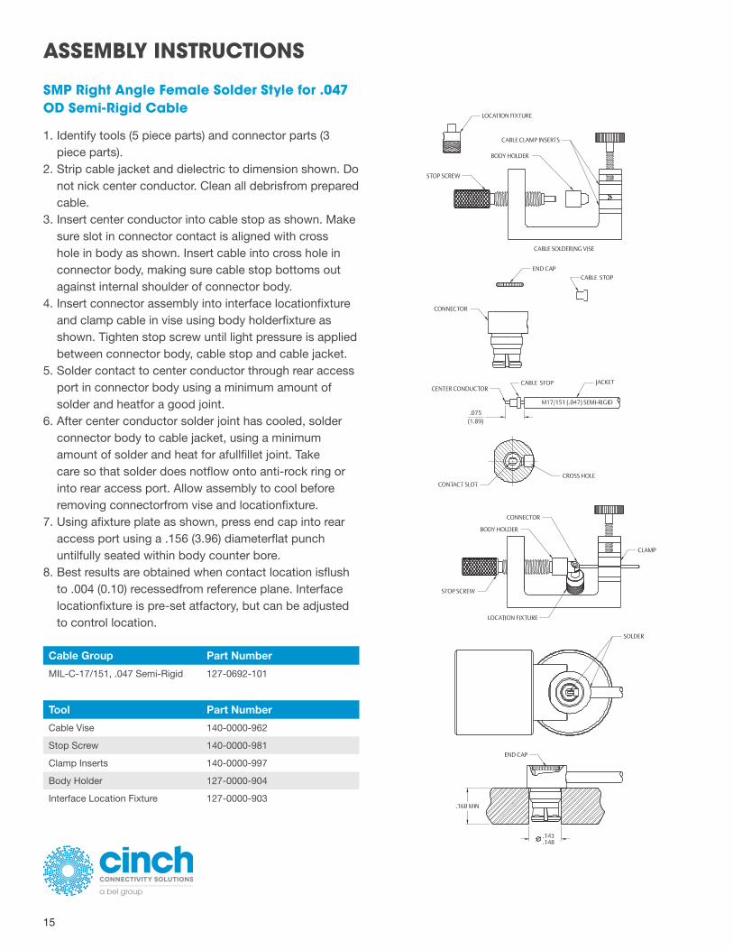
SMP Right Angle Female Solder Style for .047 OD Semi-Rigid Cable
1. Identify tools (5 piece parts) and connector parts (3 piece parts).
2. Strip cable jacket and dielectric to dimension shown. Do not nick center conductor. Clean all debrisfrom prepared cable.
3. Insert center conductor into cable stop as shown. Make sure slot in connector contact is aligned with cross hole in body as shown. Insert cable into cross hole in connector body, making sure cable stop bottoms out against internal shoulder of connector body.
4. Insert connector assembly into interface locationfixture and clamp cable in vise using body holderfixture as shown. Tighten stop screw until light pressure is applied between connector body, cable stop and cable jacket.
5. Solder contact to center conductor through rear access port in connector body using a minimum amount of solder and heatfor a good joint.
6. After center conductor solder joint has cooled, solder connector body to cable jacket, using a minimum amount of solder and heat for afullfillet joint. Take care so that solder does notflow onto anti-rock ring or into rear access port. Allow assembly to cool before removing connectorfrom vise and locationfixture.
7. Using afixture plate as shown, press end cap into rear access port using a .156 (3.96) diameterflat punch untilfully seated within body counter bore.
8. Best results are obtained when contact location isflush to .004 (0.10) recessedfrom reference plane. Interface locationfixture is pre-set atfactory, but can be adjusted to control location.
Cable Group Part Number
MIL-C-17/151, .047 Semi-Rigid 127-0692-101
Tool Part Number
Cable Vise 140-0000-962
Stop Screw 140-0000-981
Clamp Inserts 140-0000-997
Body Holder 127-0000-904
Interface Location Fixture 127-0000-903
ASSEMBLY INSTRUCTIONS
+1 507.833.8822
cinchconnectivity.com
16
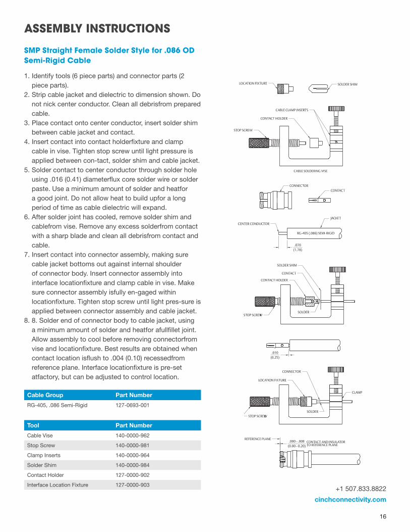
SMP Straight Female Solder Style for .086 OD Semi-Rigid Cable
1. Identify tools (6 piece parts) and connector parts (2 piece parts).
2. Strip cable jacket and dielectric to dimension shown. Do not nick center conductor. Clean all debrisfrom prepared cable.
3. Place contact onto center conductor, insert solder shim between cable jacket and contact.
4. Insert contact into contact holderfixture and clamp cable in vise. Tighten stop screw until light pressure is applied between con-tact, solder shim and cable jacket.
5. Solder contact to center conductor through solder hole using .016 (0.41) diameterflux core solder wire or solder paste. Use a minimum amount of solder and heatfor a good joint. Do not allow heat to build upfor a long period of time as cable dielectric will expand.
6. After solder joint has cooled, remove solder shim and cablefrom vise. Remove any excess solderfrom contact with a sharp blade and clean all debrisfrom contact and cable.
7. Insert contact into connector assembly, making sure cable jacket bottoms out against internal shoulder of connector body. Insert connector assembly into interface locationfixture and clamp cable in vise. Make sure connector assembly isfully en-gaged within locationfixture. Tighten stop screw until light pres-sure is applied between connector assembly and cable jacket.
8. 8. Solder end of connector body to cable jacket, using a minimum amount of solder and heatfor afullfillet joint. Allow assembly to cool before removing connectorfrom vise and locationfixture. Best results are obtained when contact location isflush to .004 (0.10) recessedfrom reference plane. Interface locationfixture is pre-set atfactory, but can be adjusted to control location.
Cable Group Part Number
RG-405, .086 Semi-Rigid 127-0693-001
Tool Part Number
Cable Vise 140-0000-962
Stop Screw 140-0000-981
Clamp Inserts 140-0000-964
Solder Shim 140-0000-984
Contact Holder 127-0000-902
Interface Location Fixture 127-0000-903
ASSEMBLY INSTRUCTIONS
17
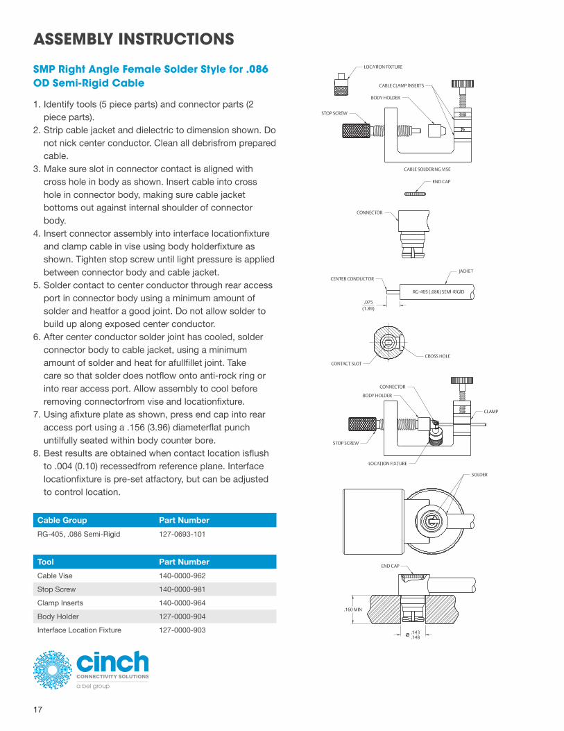
SMP Right Angle Female Solder Style for .086 OD Semi-Rigid Cable
1. Identify tools (5 piece parts) and connector parts (2piece parts).
2. Strip cable jacket and dielectric to dimension shown. Donot nick center conductor. Clean all debrisfrom preparedcable.
3. Make sure slot in connector contact is aligned withcross hole in body as shown. Insert cable into crosshole in connector body, making sure cable jacketbottoms out against internal shoulder of connectorbody.
4. Insert connector assembly into interface locationfixtureand clamp cable in vise using body holderfixture asshown. Tighten stop screw until light pressure is appliedbetween connector body and cable jacket.
5. Solder contact to center conductor through rear accessport in connector body using a minimum amount ofsolder and heatfor a good joint. Do not allow solder tobuild up along exposed center conductor.
6. After center conductor solder joint has cooled, solderconnector body to cable jacket, using a minimumamount of solder and heat for afullfillet joint. Takecare so that solder does notflow onto anti-rock ring orinto rear access port. Allow assembly to cool beforeremoving connectorfrom vise and locationfixture.
7. Using afixture plate as shown, press end cap into rearaccess port using a .156 (3.96) diameterflat punchuntilfully seated within body counter bore.
8. Best results are obtained when contact location isflushto .004 (0.10) recessedfrom reference plane. Interfacelocationfixture is pre-set atfactory, but can be adjustedto control location.
Cable Group Part Number
RG-405, .086 Semi-Rigid 127-0693-101
Tool Part Number
Cable Vise 140-0000-962
Stop Screw 140-0000-981
Clamp Inserts 140-0000-964
Body Holder 127-0000-904
Interface Location Fixture 127-0000-903
ASSEMBLY INSTRUCTIONS
+1 507.833.8822
cinchconnectivity.com
18
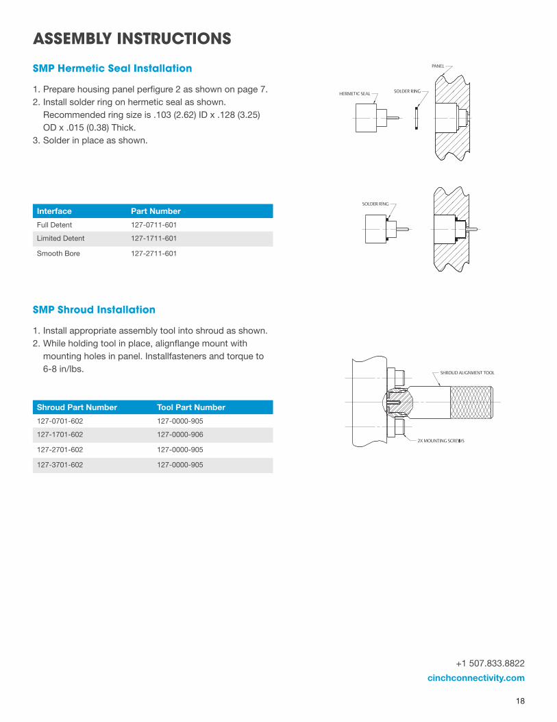
SMP Hermetic Seal Installation
1. Prepare housing panel perfigure 2 as shown on page 7. 2. Install solder ring on hermetic seal as shown.
Recommended ring size is .103 (2.62) ID x .128 (3.25) OD x .015 (0.38) Thick.
3. Solder in place as shown.
SMP Shroud Installation
1. Install appropriate assembly tool into shroud as shown. 2. While holding tool in place, alignflange mount with
mounting holes in panel. Installfasteners and torque to 6-8 in/lbs.
Interface Part Number
Full Detent 127-0711-601
Limited Detent 127-1711-601
Smooth Bore 127-2711-601
Shroud Part Number Tool Part Number
127-0701-602 127-0000-905
127-1701-602 127-0000-906
127-2701-602 127-0000-905
127-3701-602 127-0000-905
ASSEMBLY INSTRUCTIONS
19
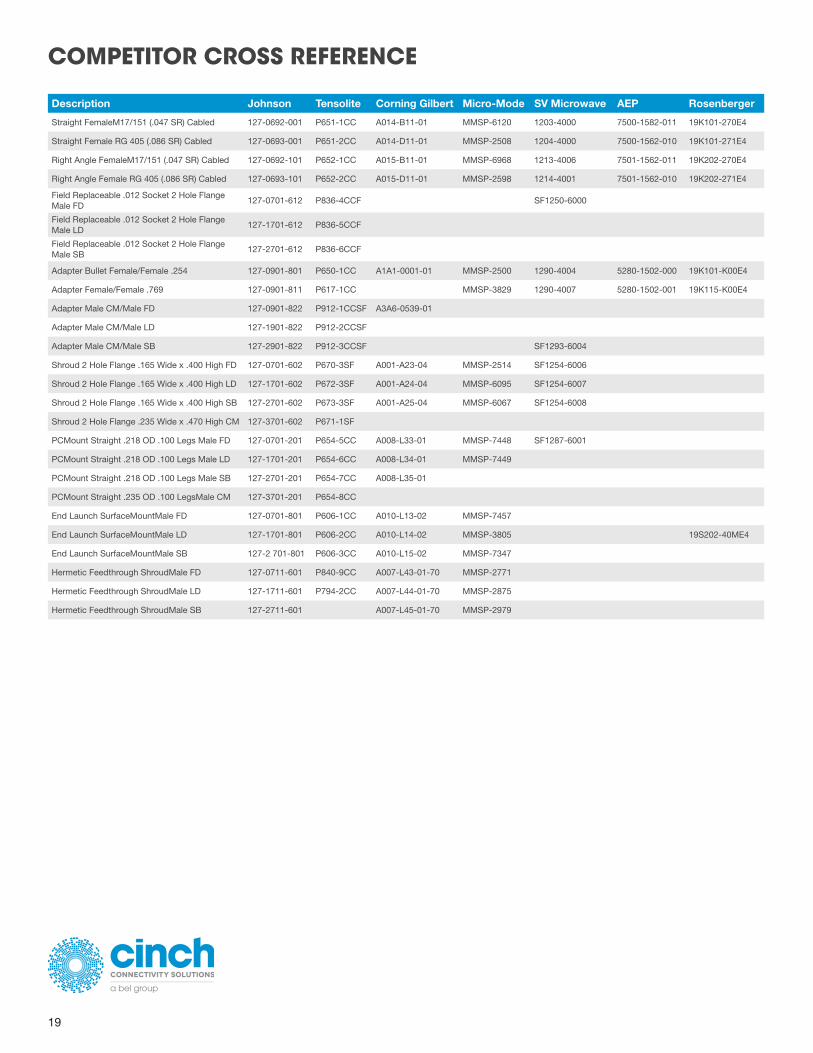
COMPETITOR CROSS REFERENCE
Description Johnson Tensolite Corning Gilbert Micro-Mode SV Microwave AEP Rosenberger
Straight FemaleM17/151 (.047 SR) Cabled 127-0692-001 P651-1CC A014-B11-01 MMSP-6120 1203-4000 7500-1582-011 19K101-270E4
Straight Female RG 405 (.086 SR) Cabled 127-0693-001 P651-2CC A014-D11-01 MMSP-2508 1204-4000 7500-1562-010 19K101-271E4
Right Angle FemaleM17/151 (.047 SR) Cabled 127-0692-101 P652-1CC A015-B11-01 MMSP-6968 1213-4006 7501-1562-011 19K202-270E4
Right Angle Female RG 405 (.086 SR) Cabled 127-0693-101 P652-2CC A015-D11-01 MMSP-2598 1214-4001 7501-1562-010 19K202-271E4
Field Replaceable .012 Socket 2 Hole Flange Male FD
127-0701-612 P836-4CCF SF1250-6000
Field Replaceable .012 Socket 2 Hole Flange Male LD
127-1701-612 P836-5CCF
Field Replaceable .012 Socket 2 Hole Flange Male SB
127-2701-612 P836-6CCF
Adapter Bullet Female/Female .254 127-0901-801 P650-1CC A1A1-0001-01 MMSP-2500 1290-4004 5280-1502-000 19K101-K00E4
Adapter Female/Female .769 127-0901-811 P617-1CC MMSP-3829 1290-4007 5280-1502-001 19K115-K00E4
Adapter Male CM/Male FD 127-0901-822 P912-1CCSF A3A6-0539-01
Adapter Male CM/Male LD 127-1901-822 P912-2CCSF
Adapter Male CM/Male SB 127-2901-822 P912-3CCSF SF1293-6004
Shroud 2 Hole Flange .165 Wide x .400 High FD 127-0701-602 P670-3SF A001-A23-04 MMSP-2514 SF1254-6006
Shroud 2 Hole Flange .165 Wide x .400 High LD 127-1701-602 P672-3SF A001-A24-04 MMSP-6095 SF1254-6007
Shroud 2 Hole Flange .165 Wide x .400 High SB 127-2701-602 P673-3SF A001-A25-04 MMSP-6067 SF1254-6008
Shroud 2 Hole Flange .235 Wide x .470 High CM 127-3701-602 P671-1SF
PCMount Straight .218 OD .100 Legs Male FD 127-0701-201 P654-5CC A008-L33-01 MMSP-7448 SF1287-6001
PCMount Straight .218 OD .100 Legs Male LD 127-1701-201 P654-6CC A008-L34-01 MMSP-7449
PCMount Straight .218 OD .100 Legs Male SB 127-2701-201 P654-7CC A008-L35-01
PCMount Straight .235 OD .100 LegsMale CM 127-3701-201 P654-8CC
End Launch SurfaceMountMale FD 127-0701-801 P606-1CC A010-L13-02 MMSP-7457
End Launch SurfaceMountMale LD 127-1701-801 P606-2CC A010-L14-02 MMSP-3805 19S202-40ME4
End Launch SurfaceMountMale SB 127-2 701-801 P606-3CC A010-L15-02 MMSP-7347
Hermetic Feedthrough ShroudMale FD 127-0711-601 P840-9CC A007-L43-01-70 MMSP-2771
Hermetic Feedthrough ShroudMale LD 127-1711-601 P794-2CC A007-L44-01-70 MMSP-2875
Hermetic Feedthrough ShroudMale SB 127-2711-601 A007-L45-01-70 MMSP-2979

![Universal MATE-N-LOK Connectors Product FactsUniversal MATE-N-LOK Connectors (Continued) Standard Density.250 [6.35] Centerline Universal MATE-N-LOK Connector Mating Combinations Connector](https://img.pdfslide.us/doc/110x75/6121c4fbac4a9135eb3bce66/universal-mate-n-lok-connectors-product-facts-universal-mate-n-lok-connectors-continued.jpg)