Embed Size (px)
Citation preview
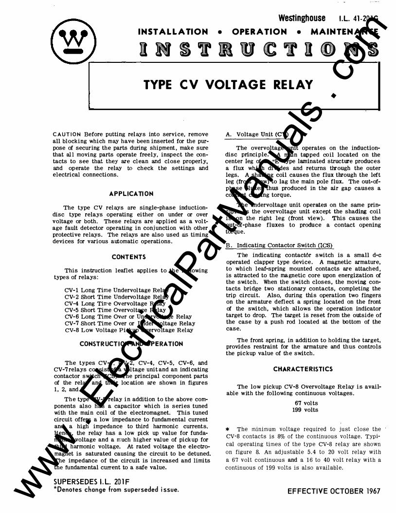
Westinghouse J.L. 41-20lG INSTALLATION • OPERATION • MAINTENANCE
INSTRUCTIONS TYPE CV VOLTAGE RELAY
C AUTION Be fore putting relays into service, remove all blocking which may have been inserted for the purpose of securing the parts during shipment , make sure that al l moving parts operate freely, inspect the contacts to see that they are clean and close properly, and operate the relay to check the settings and electrical connections.
APPLICATION
The type CV relays are single-phase inductiondisc type relays operating either on under or over voltage or both. These relays are applied as a voltage fault detector operating in conjunction with other protective relays. The relays are also used as timing devices for various automatic operations.
CONTENTS
This instruction leaflet applies to the following types of relays:
CV- 1 Long Time Undervoltage Relay CV-2 Short Time Undervoltage Relay CV-4 Long Tiwe Overvoltage Relay CV-5 Short Time Overvoltage Relay CV-6 Long Time Ov�r or Undervoltage Relay CV-7 Short Time Over or Under voltage Relay CV-8 Low Voltage Pickup Overvo ltage Relay
CONSTR UCT ION AND OPERATION
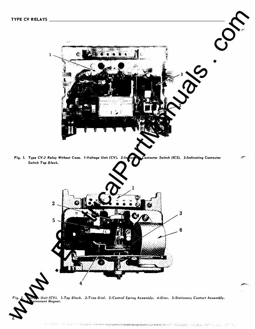
The types CV-1, CV-2, CV-4, CV-5, CV-6, and CV-7 relays consist of a voltage unit and an indicating contactor switch (ICS). The principal component parts of the relay and their loc ation are shown in figures 1, 2, and 3.
The type CV-8 relay in addition to the above components also has a capacitor which is series tuned with the main coil of the electromagnet. This tuned circuit offers a low impedance to fundamental current and a high impedance to third harmonic currents. Hence, the relay has a low pick up value for fundamental voltage and a much higher value of pickup for third harmonic voltage. At rated voltage th e electromagnet is saturated causing the circuit to be detuned. The impedance o f the circuit is increased and limits the fundamental current to a safe value.
SUPERSEDES I. L. 201 F *Denotes change from superseded i ssue.
A. Voltage Unit (CV) The overvoltage unit operates on the induction
disc principle. A main tapped co il located on the center leg of an "E" type laminated structure produces a flux which divides and returns through the outer legs. A shading coil causes the flux through the left leg (front view) to lag the main pole flux. The out-ofphase fluxes thus produced in the air gap causes a contact closing torque.
The undervoltage unit operates on the same principle as the overvoltage unit except the shading coil is on the right leg (front view). This causes the out-of-phase fluxes to produce a contact opening torque.
B. Indicating Contactor Switch (ICS)
T he indicating contact6r switch is a small d-e operated clapper type device . A magnetic armature, to which leaf-spring mounted contacts are attached , is attracted to the magnetic core upon energization of the switc h. When the switch closes, the moving contacts bridge two stationary contacts, completing the trip circuit. Also, during this operation two fingers on the armature deflect a spring located on the front of the switch, which allows the operation indicator target to drop. The target is reset from the outside o f the case by a push rod located at the bottom of the case.
The front spring, in addition to holding the target, provides restraint for the armature and thus controls the pic kup value of the switch.
CHARACTERISTICS
The low pickup CV-8 Overvoltage Relay is available w ith the following continuous voltages.
67 volts 199 volts
* The minimum voltage required to just close the CV-8 contacts is 8% of the continuous voltage. Typical operating times of the type CV-8 relay are shown on figure 8. An adjustable 5.4 to 20 volt relay with a 67 volt continuous and a 16 to 40 volt relay with a continuous of 199 volts is also available.
EFFECTI V E OCTOBER 1967 www . El
ectric
alPar
tMan
uals
. com
TYPE CV R ELAYS
1
Fig. 1. Type CV-2 Relay Without Case. 1-Voltage Unit (CV). 2-lndicating Contactor Switch (ICS). 3-lndicating Contactor
Switch Tap Block.
2
3
5
6
4
Fig. 2. Voltage Unit (CV). 1- Tap B lock. 2- Time D ial. 3-Control Spring Assembly. 4-Disc. 5-Stationary Contact Assembly. 6-P e rmanent Magnet.
2 www . El
ectric
alPar
tMan
uals
. com

TYPECVRELAYS __________________________________________________________ �I. L�-�4�1-� 20�1G
.··�.
Fig. 3. Indicating Contactor Switch (ICS).
The CV - 1 and CV-2 Undervoltage Relays, CV -4 and CV -5 Overvoltage R elays, and CV -6 and CV -7 Over or Undervoltage Relays are available in the following voltage ranges:
R a nge
55-140 55 64 1 10-280 1 10 128
T o p s
70 82 93 105 120 140 140 164 186 210 240 280
A. CV -1 and CV -2 Undervoltage Relays -- CV-4 and CV-5. Overvoltage Relays
Tap value voltage is the minimum voltage required to just close the relay contacts. At this value of voltage, the moving contacts will leave the backstop of the time dial and move to close the front contacts. Normal operation of the two relays is such that the CV-1 and CV -2 undervoltage relays will open its contacts with application of voltages greater than tap value voltage, while the CV -4 and CV -5 overvoltage relay closes its contacts with voltages greater than tap value voltage. Thus, the operaJ;ing curves of figures 9 and 10 of the undervoltage relays apply when the voltage is originally higher than tap value voltage and is suddenly reduc ed to a value shown on the curves. The operating c urves of figures 11 and 12 of the overvoltage relays apply when the voltage is initially below tap value voltage and is suddenly raised to a value shown on the curves.
B. CV -6 and CV -7 Over or Undervoltage Relays
Tap value voltage is the value of voltage at which the stationary front contact closes. The stationary back comact will close within 5% of this value.
When the relay is used as an overvoltage relay, the moving contact is made with the stationary back cortaet for vallles of applied voltage less than tap
value voltage. With ap plication of voltages greater than tap value voltage, the moving contact moves to close the front contact in a time as shown by the right-hand curves of either figures 13 or 14 .
When the relay is used as an undervoltage relay , the moving contact i s ma d e with the st ationary front contact for value s of applied voltage greater than tap value voltage. With the application of voltages les s than tap value voltage, the moving cont act moves to close the back contact in a time as shown on the left-hand curves of either figures 13 or 14 .
Trip Circuit
The main contacts will safely close 30 amperes at 250 volts d-e and the seal-in contacts of the indicating contactor switch will safely carry this current long enough to trip a circuit breaker.
3 www . El
ectric
alPar
tMan
uals
. com
TYP E CV RELAYS ____ ________ __ __________________________________________ __
IIOICATHI!o CCMTACTOR 5111 TCH-
� IIOUCTIOM Ulll T
REDIIAIIDLE TEST SWITCH
TEIIMIUl
1 82A72 5
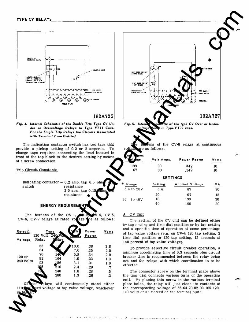
Fig. 4. Internal Schematic of the Double Trip Type CV Under or Overvoltage Relays In Type FTJJ Cas•. For the Single Trip Relays the Circuits Associated with T erm/nal 2 are OmiHed.
The indicating contactor switch has two taps that provide a pickup setting of 0. 2 or 2 amperes. To change taps req uires connecting the lead located in front of the tap block to the desired setting by means of a screw connection.
Trip Circuit Constants
Indicating contactor- 0 . 2 amp. tap 6 .5 ohms d-e switch resistance
2 . 0 amp . tap 0. 15 ohms d-e resistance
ENERGY REQU I REMENTS
The burdens of the CV-1. CV-2, CV-4, CV-5, CV-6, CV-7 relays at rated voltage are as follows:
R oted6 T o ps Volt· P ower 120 Volt 240 Volt A mps. F oetor
V olt a g e Relay Relay
55 1 10 64 128
120 or 70 140 82 1 64
240 Volts 93 186 105 2 10 1 20 240 140 280
10.0 . 38 7 . 0 .35 5 . 8 .34 4 . 0 . 33 3 . 1 . 3 1 2 . 4 . 29 1 . 8 . 28 1 . 3 . 26
Watts
3 . 8 2. 5 2 .0 1 . 3 1 . 0
. 7
. 5
. 3
6These relays will continuously stand either 1 10% of rated voltage or tap value voltage, whichever is higher.
4
LEFT WD CONTACT (FIOIT WID!}
IIIOICATIJY COtiTACTOR SWITCH EST SWITCN
FIOIT ¥11¥
1 82A727
Fig. 5. Internal Schematic of the type CV Over or Undervoltage Relay in Type FT l l case.
The burdens of the CV-8 relays at continuous voltage are as follows:
Cant i n u o us V oltage
199 67
* Range
5 . 4 to 20V
16 to 40V
A. C V Unit
Volt A m ps.
30 30
P ower F ac tor
.342
. 342
SETTINGS Settin g Applied Voltage
5 . 4 67
20 67 16 199 4 0 199
Watts
10 10
V A
30
15 30 2 0
The setting of the C V unit can be defined either by tap setting and time dial position or by tap setting and a specific time of operation at some percentage of tap value voltage (e. g. on CV-4 120 tap setting, 2 time dial position or 120 tap setting, 12 seconds at 140 percent of tap value voltage).
To provide selective circuit breaker operation , a minimum coordinating time of 0 .3 seconds plus circuit breaker time is recommended between the relay being set and tbe relays with which coordination is to be effected.
The connector screw on the terminal plate above the time dial connects various -turns of the operating coil. By placing this screw in the various terminal �" plate holes, the relay will just close its contacts at the corresponding voltage of 55-64-7D-82-93-105- 120-140 volts or as marked on the terminal plate.
www . El
ectric
alPar
tMan
uals
. com
TYPECV RELAYS·------------------------------------------------------------���.L�·�41�-2�0�1G
FIIOIIT YIIW
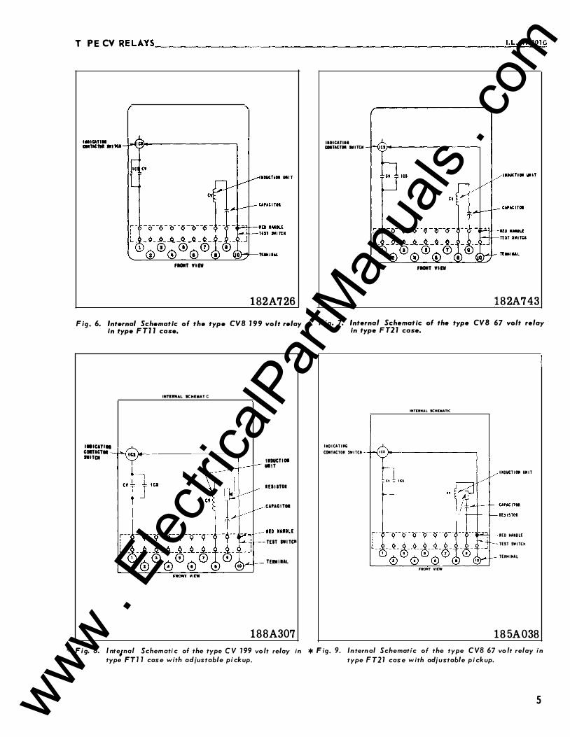
1 82A726
Fig. 6. Internal Schematic of the type CVB 199 volt relay In type F TJ 1 case.
I.ICATIII COlT ACT• IWilCI
r--
' ' '- --
INUitfiiAL SCH(IIIAT C
1
IIDUCliOI Ulll
IUIIlOI
CAPAOilOI
lUl IWilCII
lUIIIIAL
1 88A307
* Fig. 8. lnte1nal Schemati c of the type C V 199 vo lt relay in type F T 1 1 case with adjustable pick up.
IIDitlTIII 1:11111TACTOI SlfiTCM
FIIOIIT YIIW
182A743
Fig. 7. Internal Schematic of the type CVB 67 volt relay In type F T21 case.
IMDICATI•G
COIITACTOft SWITCtt
INTERNAL SCHEMATtc
'" ..._ _________ _
FltONT VI[W
UDUCTIOII UMIT
lEO tlAMDLE
-TEST SWITCh
TERM I HAL
1 85A038
* F ig. 9. In tern al Schematic of the type C VB 67 vo lt relay in type FT21 case w i th adju stable p i ck up.
5 www . El
ectric
alPar
tMan
uals
. com
TYPE CV R ELAYS __________________________________________________________ _
The nylon screw on the terminal plate holds the tap plate in position when taps are being c hanged. To
use the position on the terminal plate in which the nylon screw is used, remove the nylon screw and place it in one of the unused holes. Then remove the tap screw and insert it in the terminal plate hole.
Instantaneous Reclosing
The factory adjustment of the voltage unit contacts provides a contact follow. Where circuit breaker reclosing will be initiated immedi ately after a trip by the over voltage contact, the time of the opening of the contacts should be a minimum. This condition is obtain ed by loosening the stationary contact mounting screw, removing the contact plate and then replacing the plate with the bent en d resting against the contact spring.
For double trip relays, the upper stationary contact is adjusted such that the contact rests solidly aga inst the back stop. The lower stationary contact is then adjusted such that both stationary contacts make contact simultaneously with their respective moving contact.
B . Indicating Contactor Switch (ICS)
No setting is required on the ICS unit except the selection of the 0.2 to 2.0 ampere tap setting. This selection is made by connecting the lead loc ated in front of the tap block to the desired setting by means of the oonnecting screw.
INSTALLATION The relays should be mounted on switchboard
panels or their equivalent in a location free from dirt, moisture, excessive vibration, and heat. Mount the relay vertically by me ans of the four mount ing holes on the flange for semi-flush mounting or by means of the rear mounting stud or studs for projection mounting. Either a mounting stud or the mounting screws may be utilized for grounding the relay. The electrical connections may be made directly to the termin als by means of screws for steel panel mounting or to the terminal studs furnished with the relay for thick panel mounting. The terminal studs may be easily removed or inserted by locking two nuts on the stud and then turning the proper nut with a wrench.
For detailed FT Case information refer to I.L. 41-076.
ADJUSTMENTS AND MAINTENANCE
The proper adjustments to insure correct operation of this relay have been made at the factory. Upon receipt of the relay, no customer adjustments, other than those covered under "Settings", should be required.
Acceptance Check
The following check is recommended to insure that the relay is in proper working order:
6
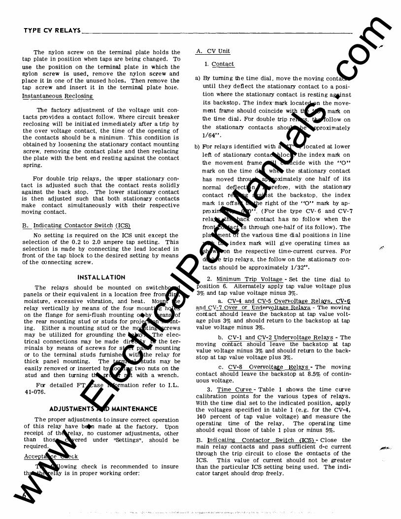
A. CV Unit
1. Contact
a) By turning the time dial, move th e moving contacts until they deflect the stationary contact to a position where the stationary contact is resting against its backstop. The index·mark located on the movement frame should coincide with the "0'' mark on the time diaJ. For double trip relays, the follow on the stationary contacts should be a pproximately 1/64".
b) For relays identified with a "T" , located at lower
left of stationary contact block, the index mark on the movem ent frame will coincide with the "0" mark on the time dial when the stationary contact
has moved through approximately one half of its
normal deflection. Therefore, with the stationary
contact resting against the backstop, the index malk is offset to the right of the "0" mark by approximately .020". (For the type CV- 6 and CV-7
relays the back contact has no follow when the front contact is through one-half of its follow). The placement of the various time di al position s in line
with the index mark will give operating times as shown on the respective time-current curves. For
double trip relays, the follow on the stationary co n
tacts should be approximately 1/32".
2. Minimum Trip Voltage - Set the time dial to position 6. Alternately apply tap value voltage plus 3% and tap value voltage minus 3%.
a. CV-4 and CV-5 Overvoltage Relays, CV-6 and CV-7 Over or Undervoltage Relays - The moving cont act should leave the backstop at tap value voltage plus 3% and should return to the backstop at tap value voltage minus 3%.
b. CV-1 and CV-2 Undervoltage Relays- The moving contact should leave the backstop at tap value voltage minus 3% and should return to the backstop at tap value voltage plus 3%.
c. CV-8 Overvoltage Relays - The moving contact should leave the backstop at 8.5% of continuous voltage.
3. Time Curve - Table 1 shows the time c urve calibration points for the various types of relays. With the time dial set to the indicated position, apply the voltages specified in table 1 (e.g. for the CV-4, 140 percent of tap value voltage) and measure the operating time of the relay. The operating time should equal those of table 1 plus or minus 5%.
B . Indicating Contactor Switch (ICS) - Close the main relay contacts and pass sufficient d-e current through the trip circuit to close the contacts of the ICS. This value of current should not be greater than the particular ICS setting being used. The indicator target should drop freely.
www . El
ectric
alPar
tMan
uals
. com
TYPECVRELAYS __________ ________________________________________________ �1-�L -�4�1�-2� 0 l�G
(/) a
16
1�
12
10
�8 u UJ (/)
6
2
0 0
TIME
11
10
8 9_,�1-o
7 6
5 �
fii 3 """ 2 1
1/ 2 �00 800 1200
P E R CEN T PICK-UP VOLTAGE
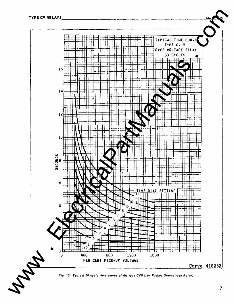
TYPICAL TIME CURVES TYPE CV-8
OVER VOLTAGE RELAY
60 CYCLES
DIAL SETTING
.. I'-
1�00
Curve 4182 52
Fig . 10. Typical 60-cyc le t ime c urves of the type CVB Low P ic k up Overvoltage Relay.
7 www . El
ectric
alPar
tMan
uals
. com
TYPECVRELAYS __________________________________________________________ __
0
8
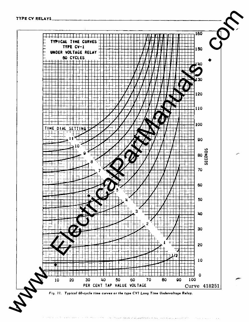
l I 1 I II I I I I 'I r- TYP I CAl TtM£ CURVES 1-- TYPl CV-1 � r- UNDER VOlTAGE RELAY II 1- IJ 1- 80 CYCL ES 1
1 11
II
I
1/ 'I
£ I
/ / J � 1/ I 1/ If T I M E D I Al SETT I NJ � If � ..1 IL _I I_ "' I�
,_ � IL 1 1'"1 1/ I/ I-" .... p..o 1 0 lL _j /
g � 1..;1 I� L,..o I i""' a' / J 1/ 1/' I--' io"" / /
l.ool-" 7
I/
� I-"
6 .... .... 5
I' II" ..... ill.J J,.ooi-" I-" I'
1-" 3 i""' 1/ ....
.... I-" 2 ...... .... � ........ .... �--
,. .... .... -I-
1 0 20 30 l.JO 50 60 70
PER CEN T TAP VAL U E VOL TAGE
• I 1 J
II
II • IJ .I
IJ 1
I I II
I
J I I II
1/_ I
!f
1/'
1/
1 v
i""'
80
I II
II
�
II
I
II 'i
I
II J
160
1�
1 110
130
120
110
100
90
II) 0 80 �
70
60
50
30
20
0 w II)
J/2
go 1 00
1 0
0
Curve 41 82 51
Fig . 1 1 . Typical 60-cycle time curves or the type CVl Long Time Undervoltoge Relay.
www . El
ectric
alPar
tMan
uals
. com
TYPECV RELAYS--------------------------------------------------------���.L�·�41�-2�0�1G
0
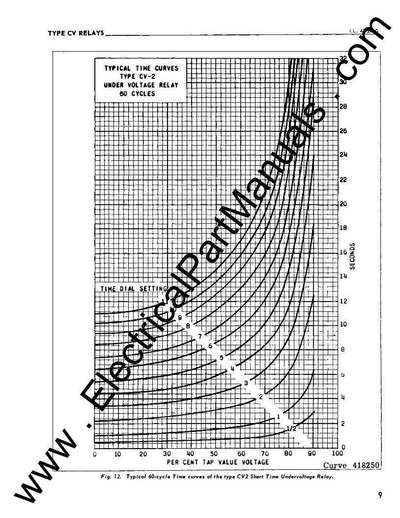
TY,ICAL T I ME CURVES
TYP E CV-2
UNDER VOLTAGE REL AY
60 CYCLES
IJ 11 r J 11 II
IIIII I
II IHJ 1/ II rr
II � IJ II---,
I� II II 'I J , , 'J II n lJ
II' " v T l � D I Al SETTIN G
""' v � J T ... r..,.. � J II l I
.... �11 "" [;Oil � � II ""'""" "'" � 10 L.o � � ] r..,.. j " II I "'" g
... "" a"' J..o' !J r � .... 7 � "' II """ 6
Ll II "'" lJ J.jll j;iii , , ... j;oo 5 II' 1/ ""'"" .... ""' � 1,1 11 � "'
3 IJ" � "fl' ,... 2 IJ ,.
�
1 """ ,;.rt .... II TTl
10 20 30 �0 50 60 70 80
P ER CENT T AP VALU E VOLTAGE
n
II
fT
---, T
rT
�
32
30
28
26
22
20
18
V)
1 6 �
1�
1 2
10
8
0
2
0
0 u \&J V)
90 100
Curve 41 82 50
Fig. 1 2. Typical 60-cyc/e Time curves ol the type CV2 Short Time Unclervoltage Relay.
9 www . El
ectric
alPar
tMan
uals
. com
TYPECVRELAYS ____________________ __ __ ____ __ ______________________ ____ __
10
160
1 !50
130
120
110
100
IJ) a z 80 8 ... IJ)
70
50
50
�0
30
20
10
0 0
TYP I CAL T I ME C U R VES
TYPE C V-�
OVER VOLTAGE R E L A Y
6 0 CYCL ES
.
I
11 Tl E O I A L SETT I N G
10
9
8
7
5
!5
�
3
2
1 '1.. J/��
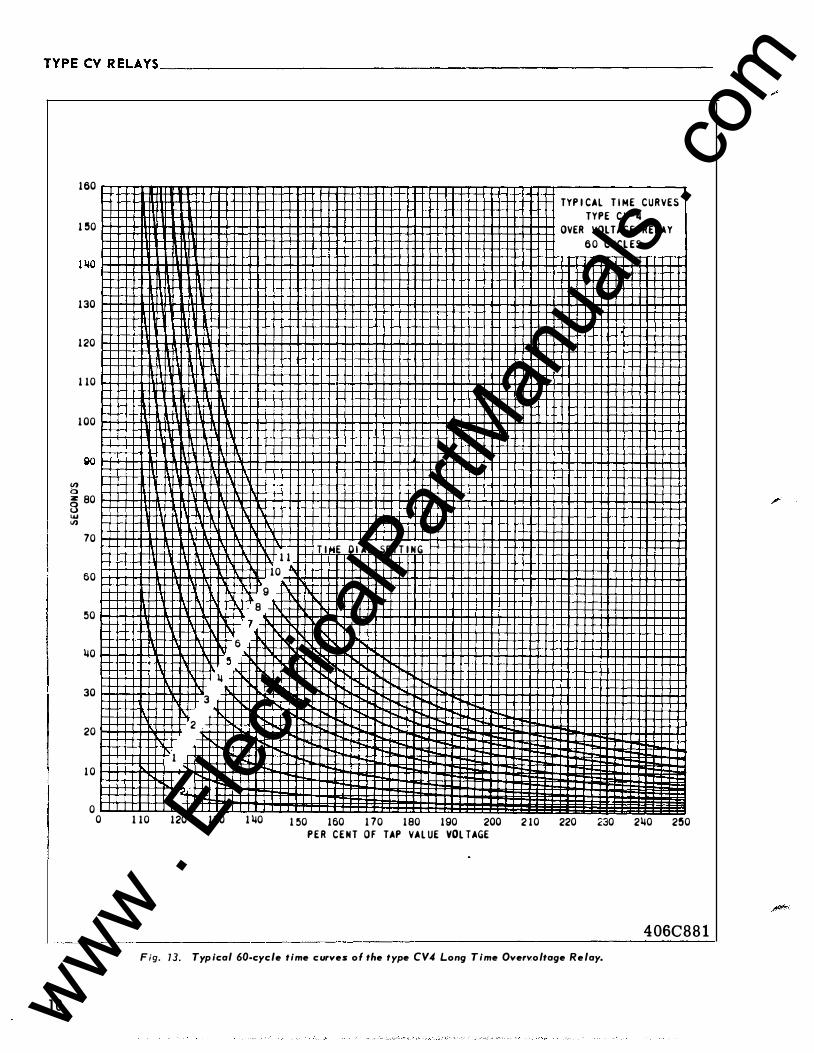
l 110 120 130 1 �0 150 160 170 180 190 200 210 220 230 2�0 2!50
P E R C E N T OF TAP VALUE VOLTAGE
406C881
Fig. 73. Typical 60-cycle time curves ol the type CV4 Long Time Overvoltage Relay.
www . El
ectric
alPar
tMan
uals
. com
TYPECV RELAYS--------------------------------------------------------�'·�L�-�41�-2�0�1G
� ... � ,.. <!I - � :I ... u., •
<n ... t ...... Z>..,� -u•u .... ... � ..,�u .,jLO ��,..� - -L ... � ,.. ... 0
• - "' -
;z -1-1-... "' .,j
• -0 ... :z: 1-
... - 2 CD
� ,.. SONOOJS
00 .... <0
10 :::t
<') N
-
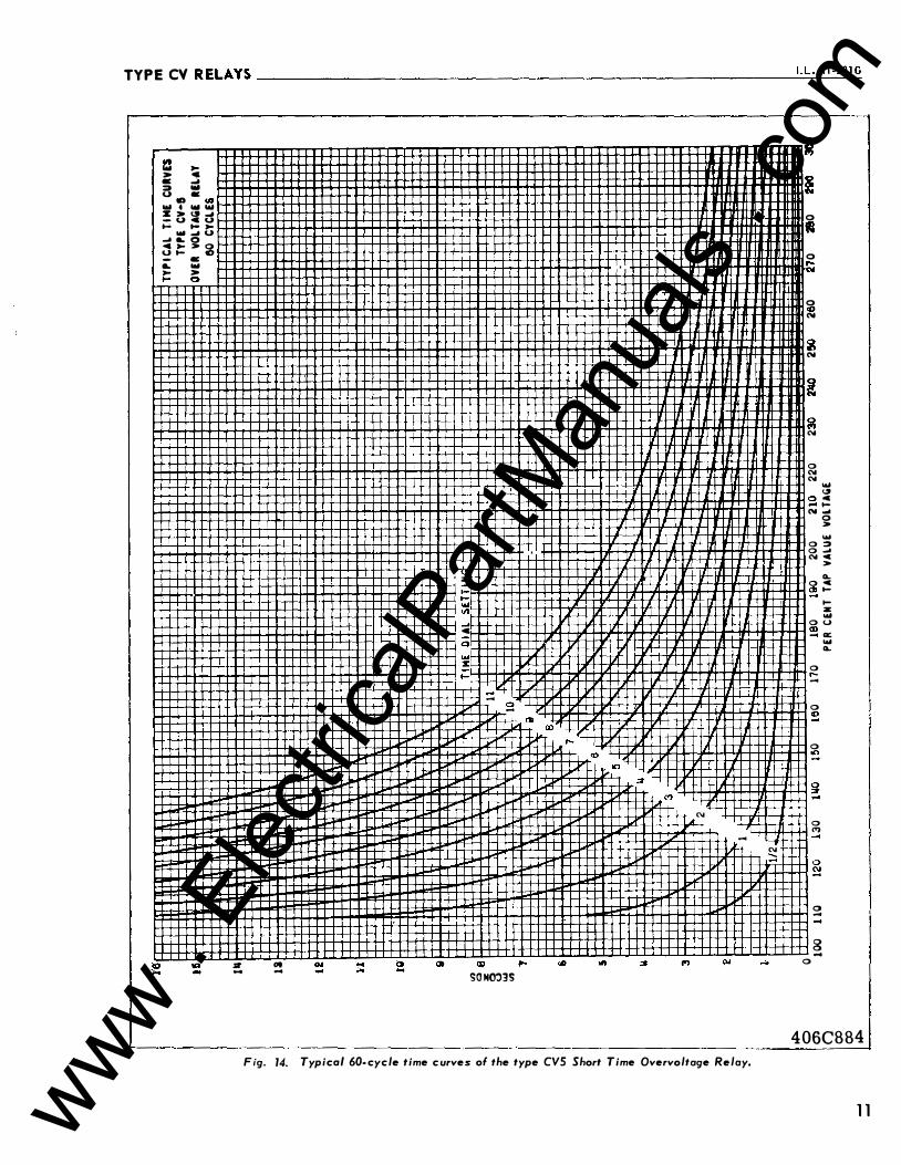
Fig. 14. Typical 60-cycle time curves of the type CVS Short Time Overvoltage Relay.
N :::;
! 0 • 0 ,.... "" 0 Cl N
� N
! � N
0 N N
2 N
0 0 N
0 � 0 s
0 ,.... -0
0
0 <')
0 -
8 -0
... "' .. 1-... 0 > ... :::» .,j c >
CL. c ....
.... ;z ... 0 a:; ... CL.
406CBB4
1 1 www . El
ectric
alPar
tMan
uals
. com
TYPECVRELAYS·----------------------------------------------------------
12
a: .., > 0
0 "' 0 0 0 Cl) SONOJ3S
0 ....
"' CD
.... c
0
... %
- sa
0 "'
.,..., ....
"' "'
0
"' ..,
2 N
0 � 0 ... N
0 N N
0 (;j g ...
0 � 0 � 0 ...
� lil � ... -�
c t-....
0 0 "'"' ...
N 3 c
0 >
N "' .... _,.. c t-
Ot-- z _..,
u "' � o§�
0 .,.
"' ::: 0 CD
0 ....
0 .,
0 "'
0 ..
i
0
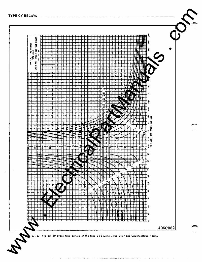
Fig. 1 5. Typical 60-cycle time curves of the type CV6 Long Time Over and Undervoltage Relay.
406C882
�
�·
www . El
ectric
alPar
tMan
uals
. com
TYPECVRELAYS ___________________________________________________________ I.L_._4_1-_20_1_G
8 ...
0 <» ..
� "'
.. ... ... > " .. c
0 Ill => � u ...
0<1> >::: ! :� ... 0 .... "'
au � !g u
0 � E: i .. ... > 0
� �
� 0 "' "'
0 "'
� � 0 � 0 ....
0 "'
� a :! g
� -
a "'
0
0 :: 'on �
SONOJ3S 0 "'
s 0 "'
R :5 0 "'
0 "
0 ...
::: � �
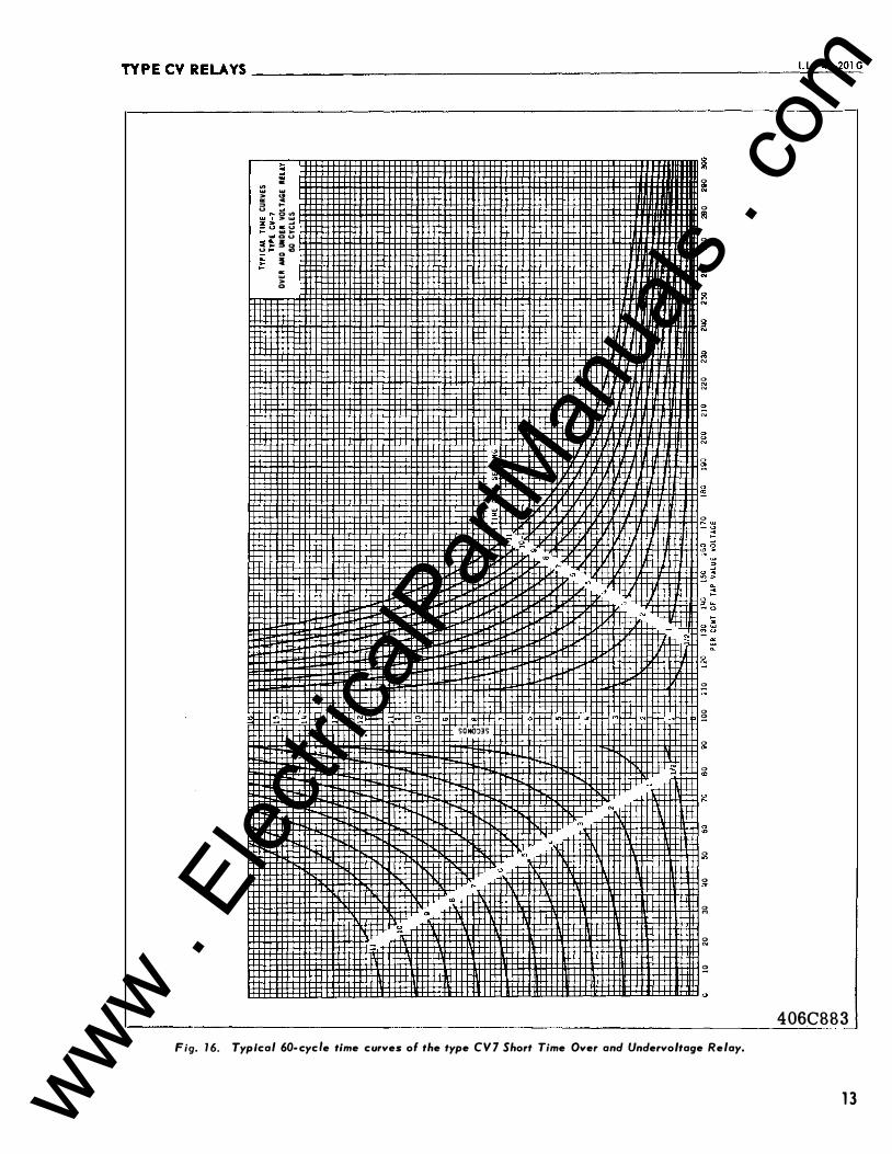
406C883
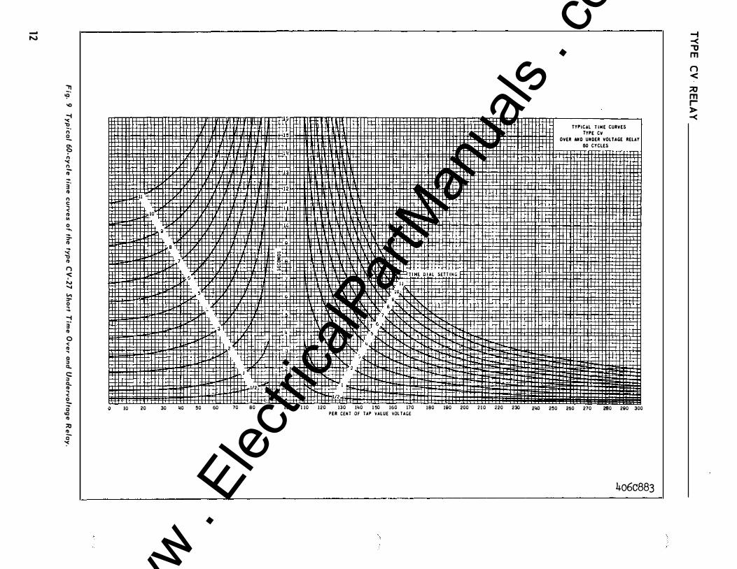
Fig. 16. Typical 60-cycfe time curves ol the type CV7 Short Time Over and Undervoltage Relay.
13 www . El
ectric
alPar
tMan
uals
. com
TYPECVRELAYS�---------------------------------------------------------
}TO TIMER START
(TIMER STOPS IIHEM AUX. RELAY CONTACT OPENS)
(TIMER STARTS IIHEM SWITCH "S" CLOSES)
A. C. SUPPLY
1 83A02 3
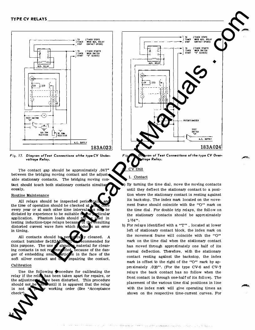
Fig. 1 7 . Diagram ofTest Connections ofthe type CV Undervoltage Relay.
The contact gap should be approximately .047" between the bridging moving contact and the adjust
able stationary contacts. The bridging moving con
tact should touch both stationary contacts simultaneously.
Routine Maintenance
All relays should be inspected periodically and the time of operation should be c hecked at least once every year or at such other time intervals as may be dictated by experience to be suitable to the particular app lication. Phantom loads should not be used in testing induction-type relays because of the resulting distorted current wave form which produces an error in timing.
All contacts should be periodically cleaned. A contact burnisher S1tl82A836H01 is recommended for this purpose. The use of abrasive material for cleaning contacts is not recommended, because of the danger of embedding small particles in the face of the soft silver contact and thus impairing the contact.
Calibration
Use the following procedure for calibrating the relay if the relay has been taken apart for repairs, or the adjustments have been disturbed. This procedure should not be used until it is apparent that the relay is not in proper working order (See "Acceptance check").
1 4
} TO TIMER START
(TIMER STOPS OHEN AUX. RELAY CONTACT OPENS)
( Tl MER STARTS OHEN SWITCH 'S" CLOSES)
TEST SWITCH
L-----��------
----_.--Q t::�·-
s_•_A_.C_.-�-PP-LY-
183A024
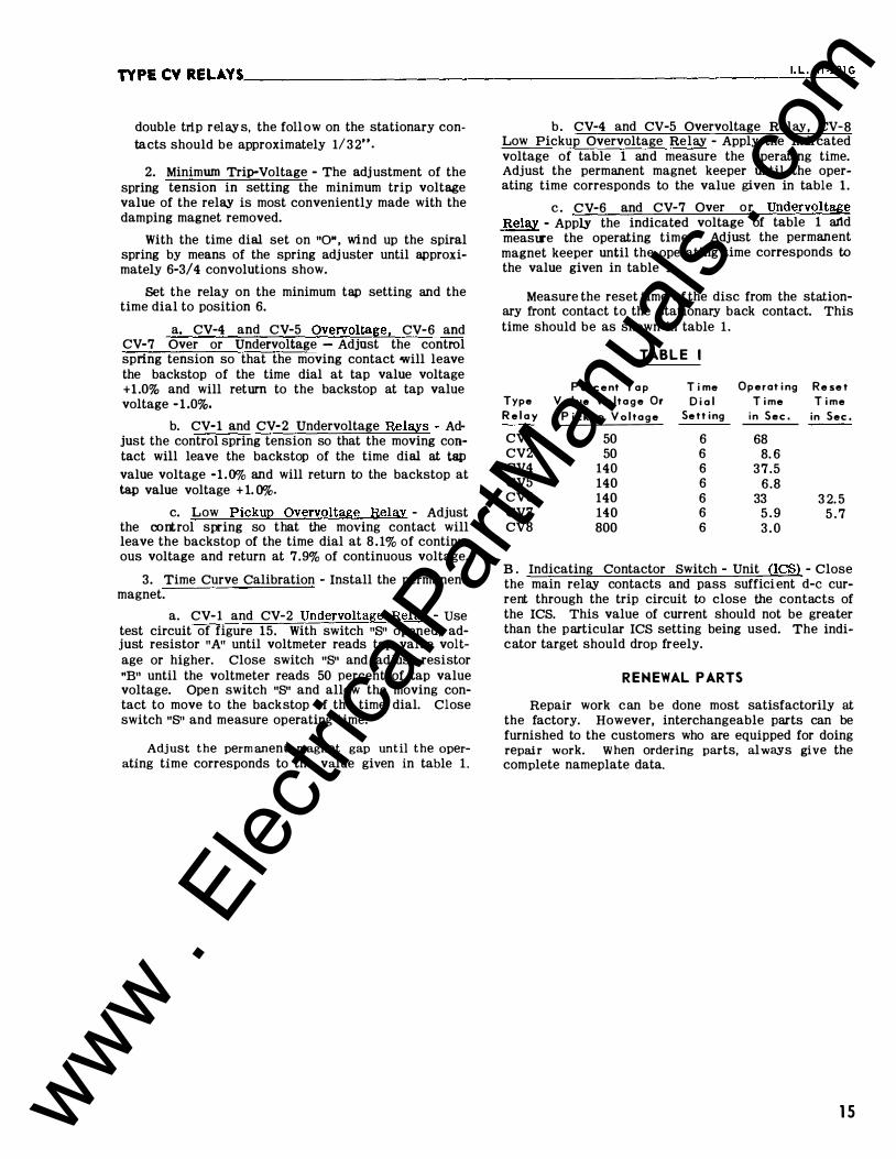
Fig. 18. Diagram of Test Connections of the type CV Over• voltage Relay.
A. CV Unit
1. Contact
a) By turning the time dial, move the moving contacts
until they deflect the stationary contact to a posi
tion where the stationary contact is resting against
its back stop. The index mark located on the move
ment frame should coincide with the "0" mark on
the time diaL For double trip relays, the foll ow on
the stationary contacts should be approximately
1/64".
b) For relays identified with a "T" , located at lower
left of stationary contact block, the index mark on
the moveme nt frame will coincide with the "0,. mark on the time dial when the stationary contact
has moved through approximately one half of its
normal deflection. Therefore, with the stationary
contact resting against the backstop, the index
mark is offset to the right of the "0,. mark by ap
proximately .020". (For the type CV-6 and CV-7
relays the back contact has no follow when the
front contact is throug h one-half of its foll ow). The
placement of the various time dial positions in 1 ine
with the index mark will give operating times as
shown on the respective time-current curves. For
www . El
ectric
alPar
tMan
uals
. com
TYPE CVRELAYS'--------------------------------------------------------'·_L_._41�·2_0�1G
double trip rel ay s, the foll ow on the stationary contacts should be approximately 1/ 3 2 ...
2. Minimum Trip-V oltage - The adj ustment of the spring tension in setting the minimum trip voltage value of the relay is most conveniently made with the damping magnet removed.
With the time dial set on "0", wind up the spiral spring by means of the spring adj uster until approximately 6-3/4 convolutions show.
Set the relay on the minimum tap setting and the time dial to position 6.
a. CV -4 and CV -5 Overvoltage, CV -6 and CV -7 Over or Undervoltage - Adjust the control spring tension so that the moving contact will leave the backstop of the time dial at tap value voltage +1 .0% and will return to the backstop at tap value voltage - 1.0%.
b. CV -1 and CV -2 Undervoltage Relays - Adjust the control spring tension so that the moving contact will leave the backstop of the time dial at tap value voltage -1 .0% and will return to the backstop at tap value voltage + 1. ()%.
c. Low Pickup Overvoltage Relav - Adjust the oortrol spring so that the moving contact will leave the backstop of the time dial at 8 . 1 % of continuous voltage and return at 7.9% of continuous voltage.
3. Time Curve Calibration - Install the permanent magnet.
a. CV -1 and CV -2 Undervoltage Relay - use test circuit of figure 15. With switch "8" opened, adjust resistor "A" until voltmeter reads tap value voltage or higher. Close switch "8" and adjust resistor "B" until the voltmeter reads 50 percent of tap value voltage. Ope n switch "8" and allow the moving contact to move to the backstop of the time dial. Close switch "8" and measure operating time.
Adjust the permanent magnet gap until the operating time corresponds to the value given in table 1 .
b . CV -4 and CV-5 Overvoltage Relay, CV-8 Low Pickup Overvoltage Relay - Apply the indi cated voltage of table 1 and measure the operating time. Adjust the permanent magnet keeper until the operating time corresponds to the value given in table 1 .
c . CV -6 and CV -7 Over or Undervoltage R elay - Apply the indicated voltage of table 1 artd measlJ'e the operating time. Adjust the permanent magnet keeper until the operating time corresponds to the value given in table 1 .
Measure the reset time o f the disc from the stationary front contact to the stationary back contact. This time should be as shown in table 1 .
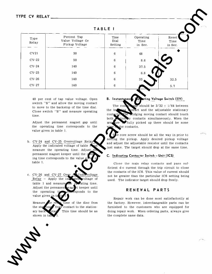
TABL E I
P erc e nt T a p Time O p e r ating R e set Type V a l ue V o lt a g e Or Di a l Time Time R e l a y Pick up V o lt a g e Setting in Sec . in Sec .
CV 1 50 6 68 CV 2 50 6 8. 6 CV 4 140 6 37.5 CV 5 140 6 6.8 CV 6 140 6 33 3 2. 5 CV 7 140 6 5 . 9 5 . 7 CV8 800 6 3 . 0
B . Indicating Contactor Switch - Unit (ICS) - Close the main relay contacts and pass suffici ent d-e current through the trip circuit to close the contacts of the ICS. This value of current should not be greater than the particular ICS setting being used. The indicator target should drop freely.
RENEWAL PARTS
Repair work can be done most satisfactorily at the factory. However, interchangeable parts can be furnished to the customers who are equipped for doing repair work. When ordering parts, always give the complete nameplate data.
1 5 www . El
ectric
alPar
tMan
uals
. com
16
TEIIMIUL AIID MOUniiG DETAILS
--(5 ���t "DIA. q HOLES FOR lnf . I90-32 �3. SCREW�
2ft I+-
'
. .....
PAIIEL DRILLIIIG OR CUTOUT FOR PRO«CTIOI MTG.
(FROIT YIEW)
� _3, �, �) T£11111Al rtf IIUMBEI
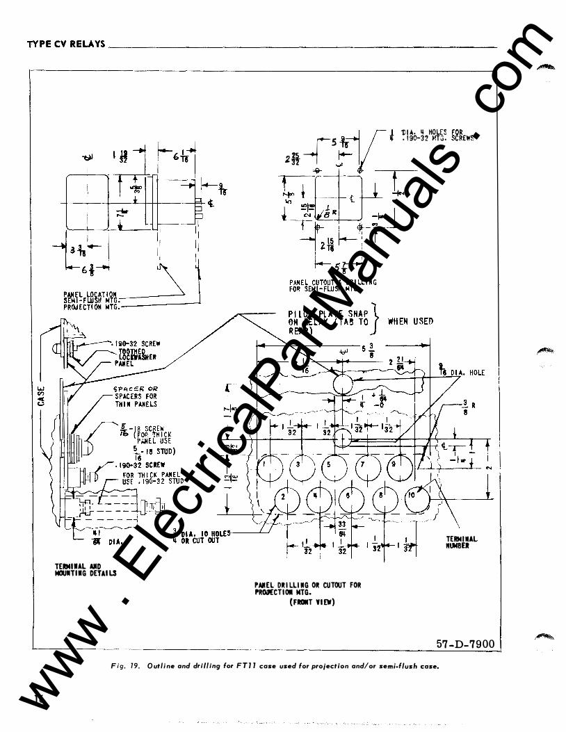
Fig. 79· Outline and d ·tt·
57 -D-7900
" '"9 for F T Jl case used for projection and/or se . f/ m•· ush case.
www . El
ectric
alPar
tMan
uals
. com
TYPE CV RELAYS----------------------------------------------------------��·�L�·�41�-2�0�1G
w Cl) oC u
.. � -
3.!. r--II -•!--
i _1__ I : : I I II II 11 11 11 11 II I I
NIIEL �TIOII� SEMI FWSH M\'1._/ / PICW!CTIOII MTI •
• I 10-32 SCit£W TOOTli£D LOCDMSKEJ
PAIIEL
3PACEIS FIJI THIII1U£LS
.!. -11 SCit£W II �FIJI THICK
MEL USE I li -·· mD) ,190-32 SCREW
I 'i"DIA.IO KOW OR CUT OUT
TERMIIIAL AIID ICIUIITIMCI DETAILS
r I ��--1 .!. DIA •• KCUS F01 2 21 ---1 - I ./' . 1 10-12 Nri.ICIM
32 ¥-_,!!
PAIIEL DRILLIIIQ 011 CUTOUT FOil PIOJECTICIII Nrl.
( FROIIT VIEW)
:lrL
N
57-D-7901
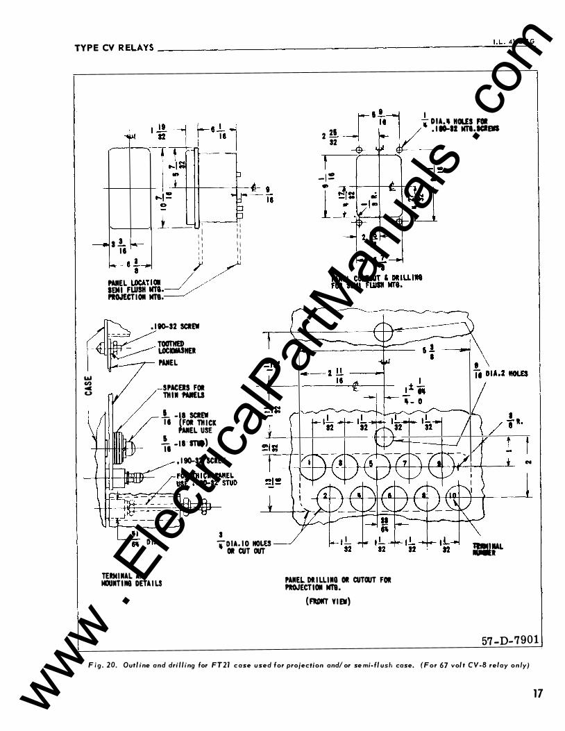
Fig. 20. Outline and drilling for FT21 c ase used for projec tion and/or se mi- flush case. (For 67 volt CV-8 relay only)
17 www . El
ectric
alPar
tMan
uals
. com

www . El
ectric
alPar
tMan
uals
. com

www . El
ectric
alPar
tMan
uals
. com
WESTINGHOUSE ELECTRIC CORPORATION R E LAY- INSTRUM ENT D IVI S I O N NEWARK, N. J.
Printed in U.S.A. www . El
ectric
alPar
tMan
uals
. com
I N ST A L L A TI O N Westinghouse 1 . L . 41-20l .2B
• O P E R A T I O N • M A I N TEN A N C E
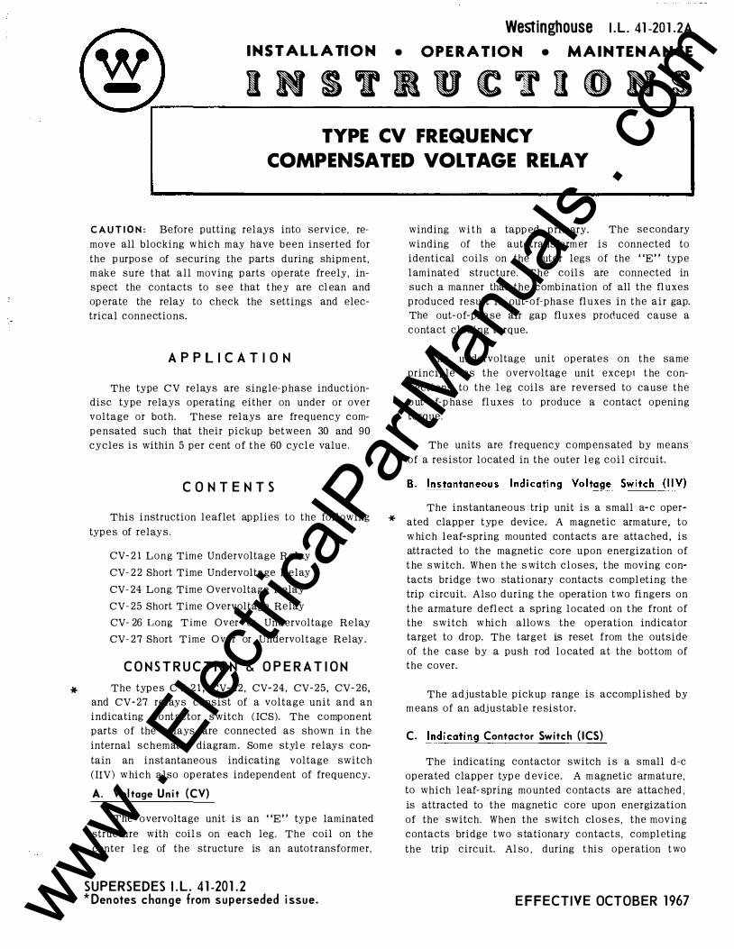
INSTRUC T I ON S TYPE CV FREQUENCY
COMPENSATED VOLTAGE RELAY
C A U TIO N : Before putting relays i nto service , re
move all blocking w hich m ay hav e been inserted for
the p urpo se of securing the parts during ship ment,
make sure that all moving parts operate fr eely, in
spect the contacts to see that t hey are cl ean and
operate the relay to check t he settings and elec
trical connectio ns.
A P P L I C A T I O N
The type CV relays are single-p hase induction
disc type relays operating either on under or over
voltage or both. Thes e relays are frequency com
p ensated such that their pickup between 30 and 90
cycles is within 5 per cent o f the 60 cycl e value .
C O N T E N T S
This i nstruction leaflet applies t o the following
typ es of relays.
CV- 2 1 Long Time Undervoltage Relay
CV- 22 Short Time Undervoltage Relay
CV- 24 Long Tim e Overvoltage Relay
CV- 25 Short Time Overvoltage Relay
CV- 26 Long Time Over or Und ervolt age Relay
CV- 2 7 Short Time Over or Undervoltage Relay.
C O N S T R U C T I O N & O P E R A T I O N
The typ e s CV- 2 1 , CV- 2 2 , CV- 2 4 , CV- 25, CV- 26,
and CV- 27 relays consist of a voltage unit and an
indicating cont actor switch ( ICS) . The compon ent
p arts of t he relays are connect ed as shown in the
internal schematic diagram . Som e style relays c on
tain an i nstantaneous indicating voltage switch
( !IV) w hi c h also operates indep endent of frequency.
A. Vol tage Un i t (CV)
The overvoltage unit is an "E" typ e laminated
structure with coil s o n each leg. The coil o n the
center leg of the structure is an autotransformer ,
SU PERSEDES I . L. 41-201.2A * Denotes change from su perseded 1 ssue.
winding with a tapp ed primary. The seco ndary
winding of the autotransformer is connected to
id entical coil s o n the o uter legs of the "E" typ e
laminated structure. The coil s are connected in such a manner that the co mbination of all the fl uxes
produced re sult in out-of-phase fluxes in the air gap.
The out- o f-phas e air gap fluxes produced cause a
contact clo sing torque.
The und ervoltage unit op erates on the same
principle as the over voltage unit exceiJt the con
nections to the leg coils ar e reversed to cause the
out-of-p hase fluxes to produce a contact opening
torque.
The u nits are frequency comp ensated by means
of a resistor located in the o uter l e g coil circuit.
The instantaneous trip unit is a small a- c oper
ated clapp er typ e device. A m agnetic armature , to
w hich leaf- spring mounted cont act s are attached, is
attracted to the m agnetic core upon energization of
the switch. When t he switch closes, t he moving con
tacts bridge two st ati onary contacts completing the
trip circuit. Also during the operation two fi ngers on
the arm ature deflect a spring located on t he front o f t h e switch which allows t h e operation indicator target to drop. The target is reset from the outside
of the case by a push rod lo cated at the bottom o f
t h e cover.
The adj ustable pickup range is ac complished by
m eans of an adj ustable resistor.
C. Indicat ing Contoctor Switch ( ICS)
The indicating contactor switch is a s mall d- e
op erated clapper type device. A m agnetic arm ature ,
to w hich leaf- spring mo unted contacts are attached ,
is attracted to the magnetic core upon energization
of the switch. When the switch clo s e s , the moving
contacts bridge two statio nary contact s , completing
the trip circuit. Al so , during this operation two
EFFECTI V E OCTOBER 1970 www . El
ectric
alPar
tMan
uals
. com
TYP E CV R ELAY ________________________________________________ _
I I I ICATIIIG C ITACTOR SWI TCH
CQNTACT POS I T I ON RELAY DE·EMEIIGIZ£0 OVER-VOLTAGE • OP£11 UMDER-YOL T AGE -CLOSED
INTERNAL SCHEMATIC
I IIDUCTION UN I T
INDUCTION UMIT
LAG COILS
RED H.I.MOLE
fEST SWITCH
TERMIIIAL
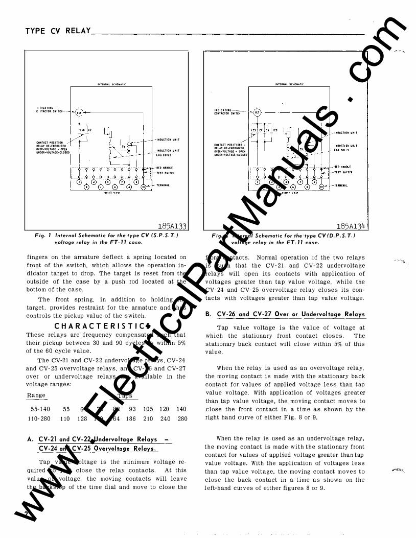
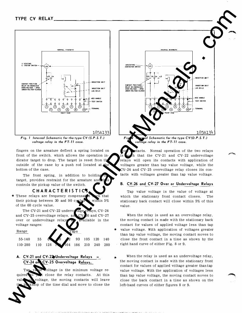
185Al33 Fig. 1 Internal Schemati c for the type CV (S. P . S. T. )
voltage relay in the FT- 1 1 case.
fingers on the armature deflect a spring l ocated on
front of the switch, which allows the op eration in
dicator target to drop. The target is reset from the
outside o f the case by a push rod located at the
botto m o f the case.
The front spring, in addition to holding the
target , provides restraint for the armature and thus
controls the pickup val ue of the s witch.
C H A R A C T E R I S T I C S The s e rel ays are frequency compensated such that
their pickup between 30 and 90 cycles is within 5%
of the 60 cycle value.
The CV-2 1 and CV- 2 2 undervoltage rel ays , CV- 24
and CV- 25 o vervoltage relay s , and CV- 26 and CV- 27
over or und ervoltage rel ays are available in the
voltage ranges:
Range
5 5- 1 40
1 1 0- 280
Tap s
5 5 6 4 70 8 2 9 3 1 0 5 1 20 140
1 10 1 28 140 164 1 86 2 10 240 280
A. CV-2 1 and CV-22 Undervo l tage Rel ays CV-24 and CV-25 Overvo l tage Relays.
Tap value voltage i s the minimum voltage re
quired to just clo s e the relay contacts. At this
val u e o f voltage, the moving contacts will leave
the back stop of the ti me dial and move to clo s e the
2
IMDICATIIIG-CONTACTOR SWITCH -
CDtiTACT POS I T I DIIS RELAY DE-ENERGIZED OVER·YOLUGE - OPEN UNDER-VOLTAGE-CLOSED
INTERNAl SCHEMATIC
� INDUCTION UNIT
185Al34 Fig. 2 Internal Schematic for the 'type CV (D. P . S. T. )
voltage relay in the FT- 11 case.
front contacts . Normal op eration of the two relays
is such that the CV- 2 1 and CV- 2 2 undervoltage
relays will open its contacts with appl ication of
voltages greater than tap value voltag e , while the
CV- 24 and CV- 25 o vervoltage rel ay cl o ses its con
tacts with voltages greater than tap value vol tage.
B. CV-26 and CV-27 Over or Undervol tage Rel ays
Tap value voltage i s the value of voltage at
which the stationary front contact clos e s . The
stationary b ack contact will close within 5% of this
value .
When the relay is used as an overvoltage relay,
the moving contact i s m ade with the s tationary back
contact for values of applied voltage l e s s than t ap
value voltage. With application of voltages great er
than tap value voltage , the mo ving c ontact moves t o
close the front cont act in a t i m e a s s hown b y the
right hand curve of either Fig . 8 or 9.
When the relay is used as an undervolt age relay ,
t h e moving contact is m ade w i t h t h e s tationary front
contact for values of app lied vo ltag e greater than tap
value voltage. With the application of voltages l e s s
than tap val ue volt age, the moving contact m o v e s t o
close t h e b ack contact in a t i m e a s shown on the
l eft-h and curves of either fi gures 8 or 9 .
www . El
ectric
alPar
tMan
uals
. com
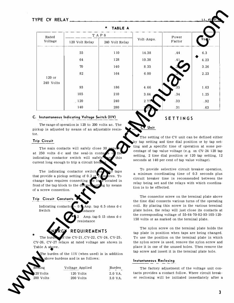
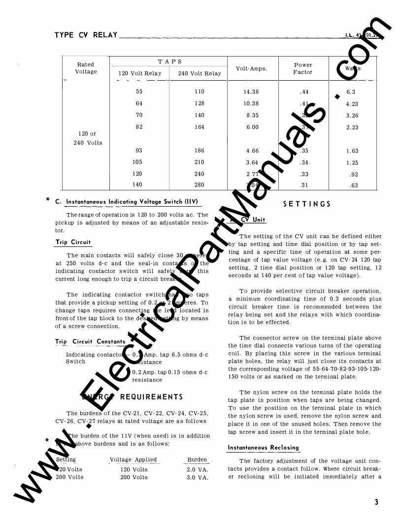
TYPE CV RELAY I . L . 41 -2o1 .2 a * TABL E A
Rated T A P S
Voltage 1 20 Volt Relay 240 Volt Relay --·
55 1 10
64 1 28
70 1 4 0
8 2 1 64 1 20 or
240 Volts
93 1 86
1 0 5 2 10
1 20 240
1 40 280
C. Instantaneous Ind icat ing Vol tage Swi tch ( I I V)
The range of op eration is 1 20 to 200 volts ac. The
pickup is adj usted by m eans of an adj ustable resis
tor.
Tri p C i rcu it
The m ain contacts will safely cl ose 30 amp eres
at 250 volts d-e and the seal- in co ntacts of the
indicating contactor s witch will safely carry this
current long enough to trip a circuit breaker.
The indicating contactor switch has two tap s
that provide a pickup setting of 0 . 2 or 2 amperes. To
chang e tap s requires connecting the lead lo cated in
front of the tap block to the de sired s etting by means
of a screw connectio n.
Trip C i rcu i t Constants
Indicating contactor - 0 . 2 Amp . tap 6 . 5 ohms d- e Switch resi stance
* 2 Amp. tap 0. 15 ohms d- e
resistance
E N E R G Y R E Q U I R E M E N T S *
The b urdens of t he CV-2 1 , C V-2 2 , CV-24 , C V-25 ,
CV-26 , CV-27 relays at rated v oltage are s hown in
Table A above .
The b urden of the 1 1 V ( when us ed) is in addition
to the above burdens and is as foll ow s :
setting
1 20 Volts
200 Volts
Voltage Applied ----
1 20 Volts
200 Volts
Burden
2 . 0 VA . 3 . 0 VA.
Power Volt- Amp s .
F actor Watts
1 4 . 3 8 . 44 6 . 3
1 0 . 38 . 4 1 4 . 23
8 . 3 5 . 39 3 . 26
6 . 00 . 37 2 . 23
4 . 6 6 3 5 1 . 63
3 . 64 . 34 1 . 25
2 . 7 7 . 3 3 . 9 2
2 . 0 4 0 3 1 . 63
S E T T I N G S
A. CV Un it
T h e setting of t h e CV unit can b e defined either
by tap setting and tim e dial p o sition or by tap set
ting and .a specific time of op eration at some per
centage of tap val ue voltage ( e . g. on CV- 24 1 20 tap
setting, 2 time dial po sition or 1 20 tap setting, 1 2
seconds at 1 40 per cent o f tap value voltage).
To p rovide sel ective circuit br eak er op eratio n ,
a m inimum coordinating t i m e o f 0 . 3 seconds plus
circuit breaker time i s r ecommended b etween the
relay b eing set and t he relay s with w hich coordina
tion i s to be effected.
The connector screw o n the terminal plate above
the time dial connects v arious turns of the operating
coiL By placing t his screw in the various terminal
plate hol e s , the relay will j ust clo se its contacts at
the corresponding voltage of 55- 64- 7 0- 8 2- 93- 1 05- 1 20-
1 50 volts or as m arked on the terminal plat e .
T he nylon screw on the terminal plate holds the
tap plate i n po sition when taps are b eing changed.
To use the po sition on the terminal plate in which
the nylon screw is us ed, remove the nylon s crew and
place it in one of the unused holes. T hen r e move t he
tap screw and insert it in the terminal plate hol e.
I nstantaneous Rec los ing
T he factory adj ustment. of t h e voltage unit con
t acts provide s a contact follow . W here circuit break
er reclo sing will b e initiated immediately after a
3 www . El
ectric
alPar
tMan
uals
. com
TYP E C V R ELAY ________________________________________________ __
l[FT HAND CONTACT ( FRONT Y I E'W )
R I GHT H U D CONTACT ( FROIIT Y I £W)
I N D I C A T I II G __COIITlCTOR SWI TCH
cv
I"DUC T I OII UII I T
L A G COILS
ED HAKOLE
TEST SWITCH
T£RMIIIAL
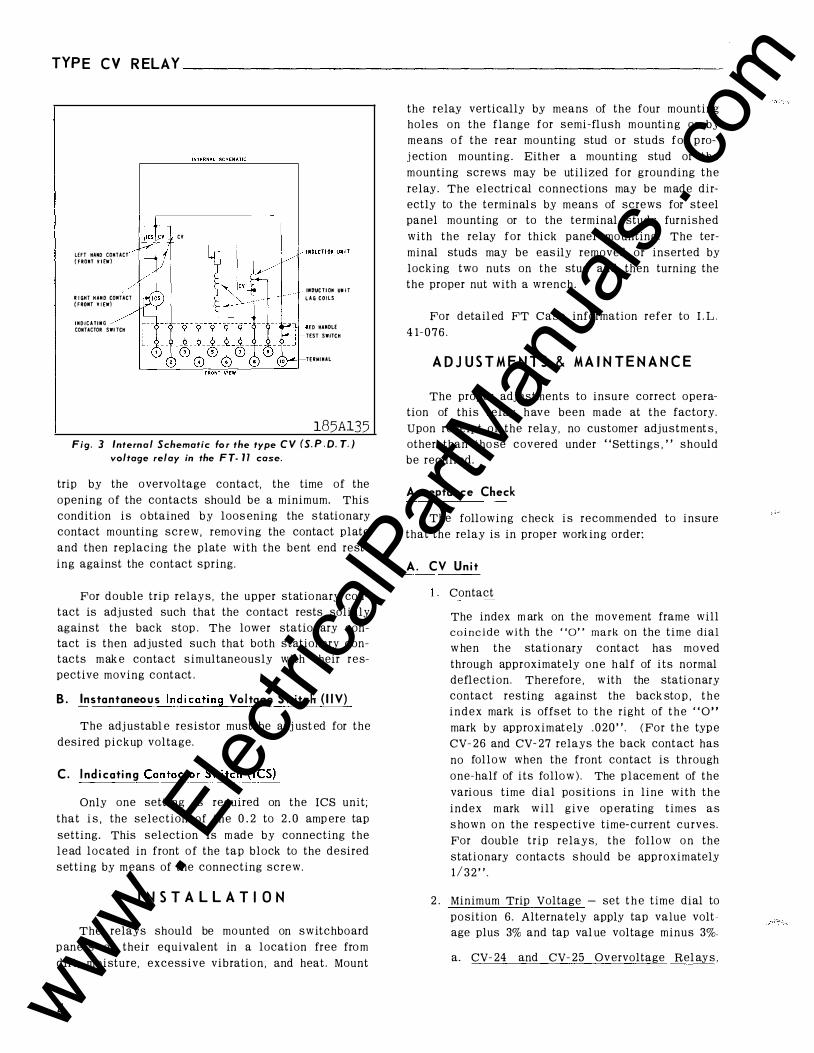
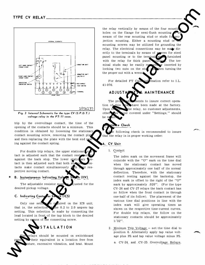
185Al35 Fig. 3 Internal Schematic fo r the type C V (S. P . D. T. )
voltage relay in the F T- 11 case.
trip by the o vervoltage contact, the time of the
opening of the contacts should be a minimum. This
condition i s o btained b y loos ening the s tationary
contact mounting screw, remo ving the contact plate
and then replacing the plate with the bent end rest
ing against the contact spring.
For double trip relay s , the upper statio nary con
tact is adj usted such that the contact rests solidly
against the back stop . The lower stationary con
tact is then adjusted such that both stationary con
tacts m ak e contact simultaneously with their res
pective moving contact .
B . Instantaneous Ind i cating Voltage Switch ( I I V)
The adj ustabl e resistor must be adj ust ed for the
desired pickup voltage.
C. I nd i cati ng Contacto��_t_c:h_il9}_
Only one setting is required on the ICS unit;
that i s , the selection of the 0 . 2 to 2 . 0 amp ere tap
setting. This sel ection is m ade by connecting the
l e ad located in front o f the tap block to the desired
setting by m ean s of the connecting screw.
I N S T A L L A T I O N
The relays should be mo unted on switchbo ard
p anels or their equivalent in a location free fro m
dirt, moisture, excessive vibration , and heat . Mount
4
the relay vertically by means of the four mounting
holes on the flange for semi-flush m o unti n g or by
me ans o f the rear mo unting stud o r studs for p ro
j ection mountin g . Eith er a mounting stud or the
mounting screws m ay be utilized for grounding the
relay. The electri c al connections may be m ade dir
ectly to the terminal s by mean s of screws for steel
panel mo unting or to the terminal stud s furnished
with the relay for thick panel mo unting . The ter
minal studs may be eas ily removed or inserted by
locking two nuts on the stud and then turning the
the proper nut with a wrench.
For detail ed FT Case information refer to I . L .
4 1- 0 7 6 .
A D J U S T M E N T S & M A I N T E N A N C E
The proper adj ustments to insure correct opera
tion of this relay h ave been m ade at the factory.
Upon receipt of the relay, no customer adjustment s ,
other than tho se covered under "Settings , " should
be required.
Acceptance Check
The following check i s recommended to insure
that the relay is in proper work ing order:
A. CV Un i t
Contact
The index m ark on the movement frame will
coincide with the "0" mark on the time dial
w hen the stationary contact has moved
through approximately o n e h alf of its normal
deflection. Therefore , w ith the stationary
contact resting against the back sto p , t h e
i n d e x mark is offs et to t h e right of t h e " 0 " mark by approximat ely . 0 2 0 " . ( For t h e typ e
CV- 2 6 and CV- 27 relays the b ack cont act has
no follow when the front contact is through
one-half of its follo w ). The p l acem ent of the
various time dial po sitions in line with the
index m ark will give op erating times as
s hown o n the r e sp ective time- c urrent curves.
For double trip relays, the follow o n the
stationary contacts s hould be approximately
1 / 3 2 " .
2 . Minimum Trip Voltage - set t h e time dial to
po sition 6. Alternately apply tap value volt
age plus 3% and tap val ue voltage minus 3%.
a. CV- 24 and CV- 25 Ov ervoltage Rel ay s ,
www . El
ectric
alPar
tMan
uals
. com
TY P E CV R ELAY----------------------------------------------------���.L�-�41�-2�0l�J�_s
CV- 2 6 and CV- 27 Over or Undervoltage
Relays - The movi ng c ontact should
leav e the back stop at tap value voltage
plus 3% and sho uld return to the b ack
stop at tap value voltage minus 3%
b. CV- 2 1 and CV- 2 2 Undervolt age Relays
The moving contact s ho uld le ave the
b ack stop at t ap value voltage minus 3%
and should return to the b ackstop at tap
value voltage plus 3%.
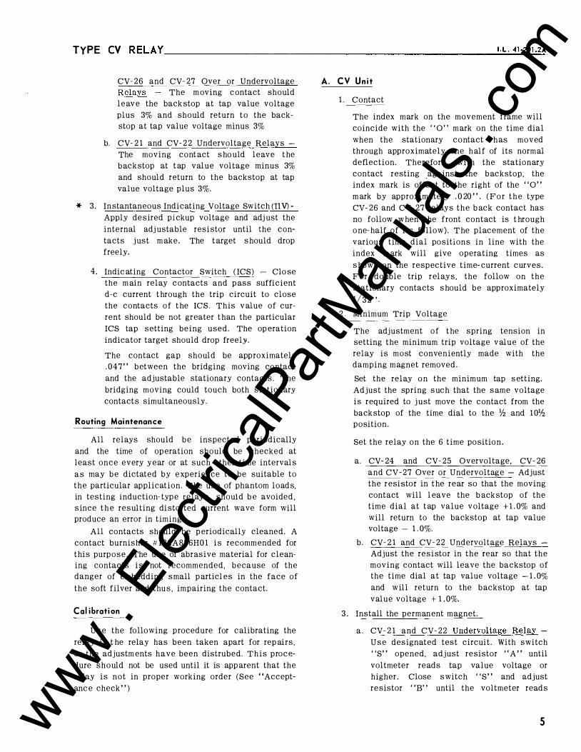
3 . In stantaneous Indicating Voltage Switch (liV) Apply de sired pickup voltage and adjust the
internal adj ustable resi stor until the con
tacts j ust m ake. The t arget s hould drop
freely.
4 . Indicating Contacto r Switch (ICS) - Close
the m ain relay contacts and p as s sufficient
d-e current t hrough the trip circuit to close
the contacts o f the res . This value of cur
rent should be not gr eater than the particul ar
res tap setting being used. The op eration
indicator target should drop freely.
The contact gap should b e appro ximately
. 047" between t he bridging m o ving contact
and the adj ustable stationary contacts . The
bridging mo ving could touch both stationary
contacts simultaneously.
Routing Maintenance
All relays should b e inspected periodically
and the time o f op eration s hould b e checked at
least once every year o r at such other time intervals
as may b e dictated by experience to be suitable to
t he particular application. T he use of phantom loads,
in testing induction- typ e relay s , should be avoided,
since the resulting distorted current wave form will
produce an error in timing.
All contacts should be perio dically cleaned. A
contact burnisher # l 82A836H0 1 i s recomm ended for
this purpose. The u s e of abr asive material for cl e an
ing contacts i s not recomme nded, b ecause of the
danger of embedding small p articl es in the face o f
t h e soft fil v e r and t h u s , impairing t he contact.
Cal ibration
Use the following p rocedure for calibrating the
relay if t he relay has been tak e n apart for rep airs ,
or the adjustm ents have been distrubed. This proce
dure should not be used until it i s app arent that the
relay is not i n prop er working o rder (See "Accept
anc e check " )
A. CV Unit
1 . Contact
The index m ark on the mo ve ment frame will
coincide with the " 0 " m ark on the time dial
when the stationary contact h as moved
through approximately one half of its normal
deflectio n . Therefore , with the stationary
contact re sting against the b ack stop , the
index mark is offset to the right of the "0 " m ark by approximately . 0 20 " . (For the typ e
cv- 26 and cv- 2 7 relays the b ack contact h as
no follow w hen the front contact is t hrough
one-half of its follow ) . T he placement of the
v arious time dial po sitions in line with the
index m ark will give operating times as
shown on the respective time- current curves.
For double trip r el ay s , the follow on the
stationary contacts s hould b e app roximately
1 / 3 2 " .
2 . Minimum Trip Voltage
The adj ustment of the spring tension in
setting t he minimum trip voltage value of the
relay is most conve ni ently m ade with the
damping m agnet removed . * Set the relay o n the m inimum tap setti ng .
Adj ust the spring until the c ontact j ust
leaves the b ackstop of the t ime dial at the
1 0Yz positi o n within 0.5 volt of t he value
that it j u st leav e s t he bac kstop with t he tim e
dial set at the lh position. Set the relay on the 6 time po sitio n .
a. CV- 24 and CV- 25 Overvoltage, CV- 26
and CV- 27 Over or Und ervoltage - Adj ust
the resistor in t he rear so that the moving
contact will 1 eave the b ack stop of the
time dial at t ap val ue v oltage + 1 . 0% and
will return to the back stop at tap value
voltage - 1 . 0%.
b . CV- 2 1 and CV- 2 2 Undervoltage Relays -
Adjust t he r esistor in the rear so that the
moving contact will leave the b ackstop of
the time dial at tap value voltage - 1 . 0%
and will return to the back stop at tap
value voltage + 1 . 0%.
3. Install the perman ent m agnet.
a. CV- 2 1 and CV- 2 2 Undervoltage Relay -
U s e designated test circuit. With switch
"S " opened, adjust resistor " A " until
voltmeter reads tap value voltage or
higher . Clo se s witch "S" and adjust
re sistor ' 'B ' ' until the voltmeter reads
5 www . El
ectric
alPar
tMan
uals
. com
TYP E CV R ELAY ________________________________________________ _
6
T A B L E I
Typ e P ercent Tap
Rel ay V alue Voltage Or
P ickup Voltage
CV 2 1 50
CV- 2 2 5 0
CV- 24 1 40
CV- 25 1 40
CV- 26 1 40
CV- 27 1 4 0
40 p er cent of t ap value voltage. Open
switch "S " and allow the moving contact
to move to the back stop of the time dial .
Clo se s witch "S " and m e asure op erating
tim e .
Adj ust the permanent m agnet gap until
the operati n g time corresponds to the
value given in table L
b . CV-24 and CV- 25 O vervol t age Relay -
Apply the i ndicated voltage of table 1 and
m eas ure the op erating time. Adj ust the
permanent m agnet k e eper until the operat
ing time c orresponds to the val ue given in
table L
c . CV- 2 6 and CV- 27 Over or Undervoltage
Relay - Apply the i ndic ated voltage of
table 1 and m easure the operating ti m e .
Adj ust t h e p ermanent m agnet keeper until
the op erating time corresponds to the
value given in table L Measure the reset time of the dis c from
the stationary front contact to the station
ary back contact. This time should be as
shown in table 1 .
I
Time Operating Reset Dial Tim e Time
Setting in Sec. in Sec.
6 68
6 8 . 6
6 3 7 . 5
6 6 . 8
6 3 3 3 2 . 5
6 5 . 9 I 5 . 7
B . I n stantaneous Indi cati ng Vo ltage Swi tch ( I I V)
The contact gap should be 3/32 ± 1 / 64 between
the bridging cont act and the adj ustable statio nary
contacts. The bridging moving contact s hould touch
bo th station ery contact s simultaneously . When the
arm ature is fully picked up there should b e some
wipe of the contact s .
T h e core screw should be all the way i n prior t o
setting the p ickup . Apply de sired pickup voltage
and adj ust the adj ustable resistor until the contact s
j ust mak e. The target should drop at the same time.
C. I n di cati ng C()lltactor Swi t�h_- Uni_t_(ICSl_
Clo s e the m ain relay contacts and p as s s u ffi cient d-e current through the trip circuit to close
the co ntacts of the res. This value of current should
not be greater than the particular res settin g being
used. The indicator target should drop fr eely.
R E N E W A L P A R T S
Repair work can b e done most satisfactorily at
the factory. Ho wever, i nterchangeable parts can be
furnished to the customers who are equipped for
doing repair work . When ordering part s , always give
the complete name data.
www . El
ectric
alPar
tMan
uals
. com
TYPE CV RELAY ___________________________________________________ ,_.
L_. _
41�
��
o1_.
2�
B
11 11 1 11 11 1 I I I I I 160
f- TYP I CAL T t ME CURVES t-- TYPl CY 1- 1 50 f- UMOER VOlTAGE RELAY 1- 60 CYCL ES fT II f- Il l IT 1 �0
If 1/ IJ 1/ 1 30
II J 1/ 1/ J --, 1 1 1 20
t-r- -I 1 10 II J
/ 1 J 11 1./ 1 00 l..ol If rT T I M E 0 1 AL SETT UH """ 1/ _ I I 7 r,- J II .... I-' u · [,i [.; rT 90 l.oof-'"
�.ooloooo 1 0 L; II' IT / I V) ,; II
g 0 .... 80 �
l.ool-' a' � 1/ 7 u ""' II' w
1,; ..... ./ 7 II V) ... 7 � 70 7 1,; � l.oo II' .... 6 j 1/ I;' 60 .... 7 7 1-' 5 ... 1/ � II" J.,. .... � � 50 L,.. ... 1-- .... ..... 3 1/ .... � 1-1-+-" J.o' 1/
... 2 IJ ......... ),<' 30 IJ I
j..o 1 J.,..j;O 20 � � L,.. /2 j;;li"' ... 1 0 L...oi"" L...o ....
0 0 10 20 30 l+O 50 60 70 80 go 1 00
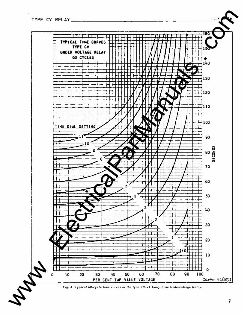
P ER CENT TAP VALUE VOLTAGE Curve 418251 Fig. 4 Typ ical 60-cycle time curves or the type CV- 2 1 Long Time Undervo ltage Re lay.
7 www . El
ectric
alPar
tMan
uals
. com
TYP E CV R EL AY-------------------------
0
8
lYr i CAL T I ME CURVES
TYPE C�
UNDER VOL TAGE REl AY
60 CYCL ES
•
1 1 .
II I II I
I
ll I I ll l
II II I II II I J
_l
IJ II
II II 1 r , , If II
IL_ Ll 'I lJ � I
If' J I It' J ,l
� I; It' L IJ I II T l �I D I Al SETTIN G
I' io"" If" I I I "" 1.;' � LJ IJ I I I I
1 1 ,_ !.;' 1..1' !I IJ "" � � � If II .... r- 10 I.; ...... 1 IL J .... B � 1.;'
.... � 8 ... "" J J I I""' 7 I' .,. 'I I-' , . 6 1/ I"" � ... � I' ...... 5 If" 1/ ""'""" """' � I"" � � II
...... 3 , ... ,... II" , , . - 2 .... I""' 1.;'
1
. ,J/'E � I . I I I I 10 20 30 �0 50 60 70 80
PER CEN T TAP VAL U E VOL TAGE
I II
II
II
90
32
30
28
26
22
20
18
U)
1 6 �
1 �
1 2
10
8
0 ,,
2
0 100
0 u \.LI U)
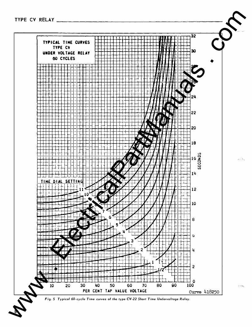
Cu...-ve 418250 F i g. 5 Typical 60- cycle Time curves of the type CV-22 Short T ime Undervo ltage R elay.
www . El
ectric
alPar
tMan
uals
. com
TYPE CV RELAY ____________________________________________________ I
.L_._
41_
�_
o_L
_2 B
1 60
1 50
1 110
130
120
(/) a
1 10
100
90
z 80 8 .... (/)
70
60
50
110
30
20
1 0
0 0
::'\;
8
7
0 !5
II 3
2
IS 1 r "': . 1/!)
1 10 120 130 1 110
TYP I CA L T I M E C U R V ES
T Y P E C 'i
OVER VOL T AG E R E L A Y
60 CYCL ES
IS 1 1 T I E D I A L SET T I N G
10
g
1 50 160 170 180 1 90 200 210 220 230 2110 2!50 P E R C E N T OF TAP V A L U E VOL TAGE
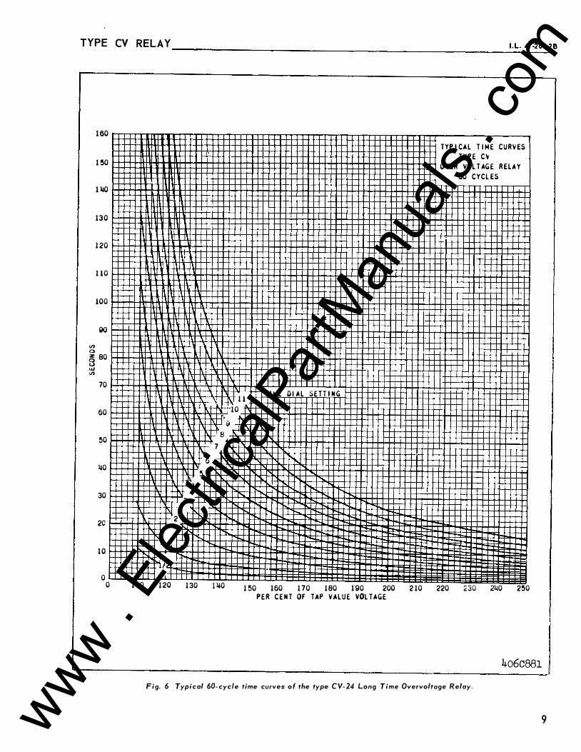
4o6C881 Fig. 6 Typical 60- cyc/e time curves of the type CV- 24 Long Time Overvoltoge Relay.
9 www . El
ectric
alPar
tMan
uals
. com
TYPE CV R ELAY ________________________________________________ __
10
en 1M ,.. > c ... � ::I ...
u ... en ... ... ... :Z: > UO � u c u .... .... ,..
... .... .., -' L O . ,.. .., .... -
L ,.. ....
>
c ... > 0
... ..
0 co
f !
l
;z -
t-t-... <J') ..... c -
0 ...
:z: ....
-- � a.
Q) r-
<() 10
� (')
"'
-
;I Gil - -
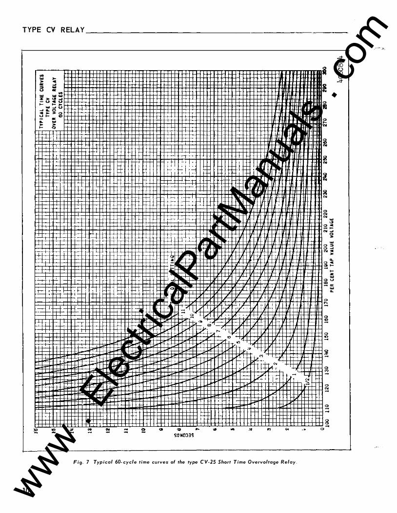
Fig. 7 Typ ical 60- cycle time curves of the type C V-25 Short Time Overvoltage Relay.
� � co 0 \0 0 ...::t ! 0
tQ 0 ,._ "'
0 C) "'
� "'
� � "'
0 "' "'
... <.5 o -c ... .... "' �
0 > ...
0 :::0 0 -' "' ..
>
L o c � ....
.... ;z ...
o u CD - a: ... L
0 r--
0 co -
0 tO
g -
0 M
"' ..... -
0 "' -
0 -
8 ...
0
www . El
ectric
alPar
tMan
uals
. com
TYPE CV RELAY ______________________________________________________ I
._L
_.4_
1_-2
_o1
_.2
_B
..
� ... ... c ... ... > .. c c :::> ,_ u ... i :: ll > ... - u a:: u ,_ ... ... "' 0 U ..... ... .. <C >- ::J O 0 ,_ C>
0 .... .. ... .. .... "' ...
> 0
0 "'
0 0
0 <D
so Nons
0 ....
"'
,_ ....
"' ... ..
... % ....
<D
- sa
....
0 It)
"' .. ....
i! ...
0 � 0 ... "'
0 ... N
� N
8 N
0 � 0 !!! 0 � � 0 "'
:i ... _ .... .. ,_ "' ...
0 0 "' > - ... 3
c 0 > � "' - a.. ..
,_
0 ,_ - :;.!:!: _ ..,
0
a:
0 � o§� 0 "'
� 0 a>
"' 0 ....
0 <D
0 "'
0 :#
� 0 N
� 0
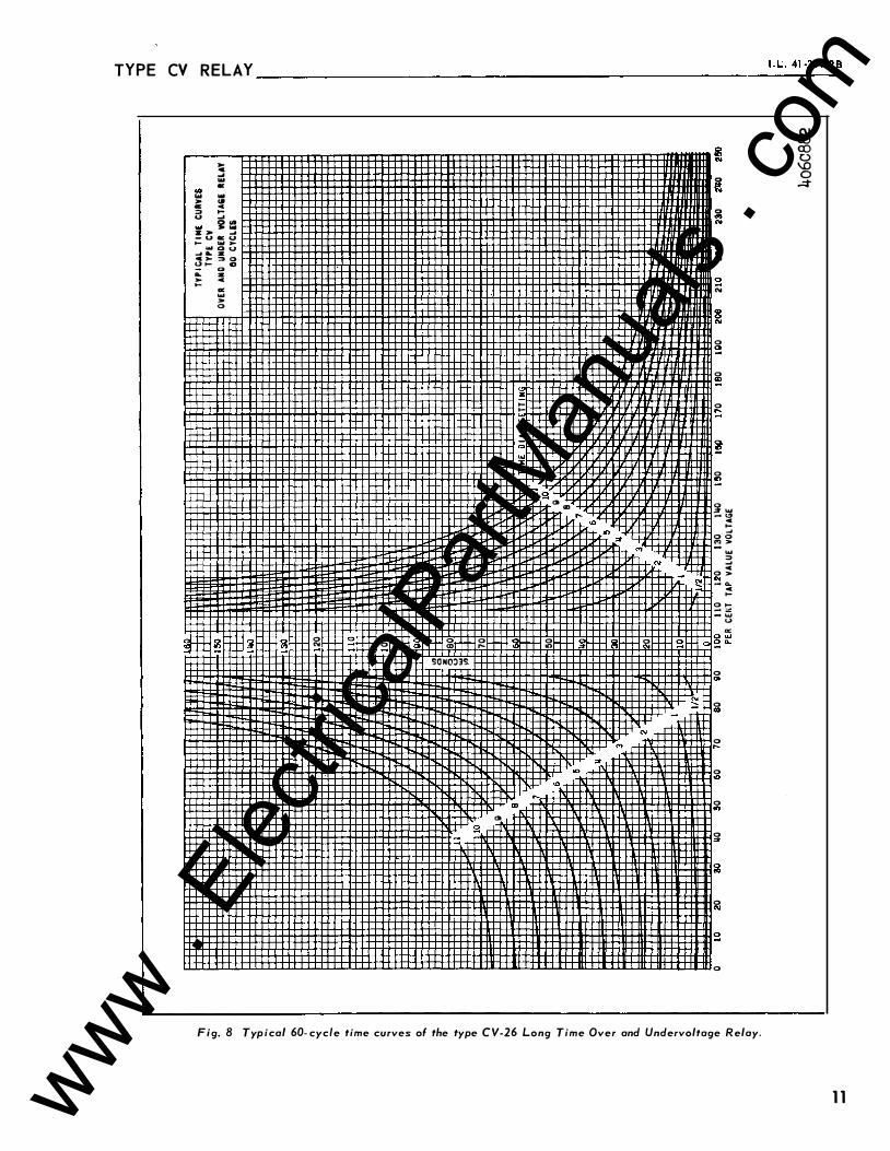
Fig. B Typ ical 60- cyc/e time curves of the type CV-26 Long Time Over and Undervoltage Relay.
C\1 co co 0 \.0 0 .=t
1 1 www . El
ectric
alPar
tMan
uals
. com
-N
:!! '!l '()
-t '< "tl n 2.. 0. ? n '< n iD ... 3' .,. n c: ... '< .,. .. 0 ..... ;. .,.
� .,. I') ;::: N � "' � � -t 3 .,. 0 '< .,. ... Q ::J Q, c: ::J :} ... '< 2.. ii IQ .,. :0 .,. Q �
11
10
...
6
10 20 30 �0 50 60
T I NE D I AL SETT I NG '
11,
l!l ll l l�llrHJii1llF:}
1/2 H-EI::l-ttU lin ! I ! ! I ! I ! I I I II ! ! ! ! I I I ! I I 70 80 90 IOD 1 10 120 130 1�0 1 50 160 170 180 190 200 2 1 0 220 230
PER CENT OF TAP VALUE VOL UGE
TYPICAL T INE CURVES
TYPE CV
OVER AIID UNDER VOLTAGE RELAY
60 CYCLES
• 2� 250 250 270 280 290 300
4o6c883
-f -< "'tJ m n < ;;o m r> -<
www . El
ectric
alPar
tMan
uals
. com
TYPE CV R ELAY
, To :' T I MER
STOP
' TO I T I MER
) START
( T I MER STOPS WHEN AUX. RELAY CONTACT OPEN S )
( T I MER STARTS WHEN SWI TCH "S" CLOSES)
A. C. SUPPLY
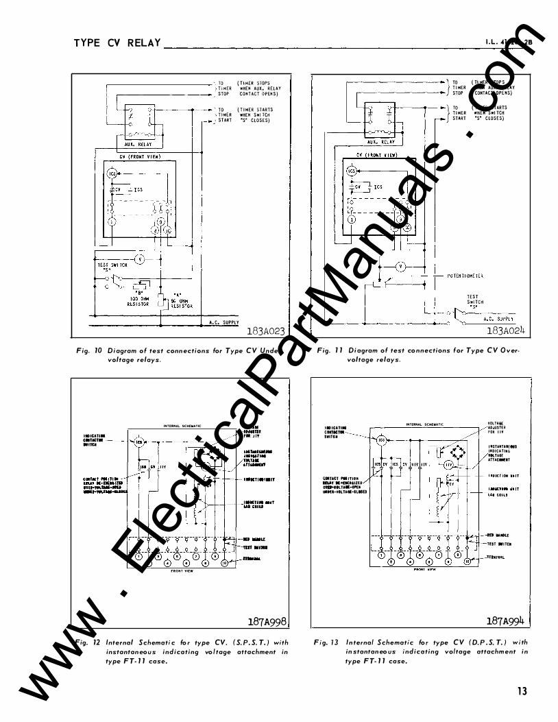
183A023 Fig. 10 Diagram of test conn ections for Type CV Under
voltage relays.
INTERNAL SCHEMATIC
I• ICATIM c•TM:TOI ---_._..! •nu
FRONT VIEW
187A998 Fig. 12 Internal Schemati c fo r type CV. ( S. P. S. T. ) with
instantan eous indicating vo ltage attachment in type FT- 1 1 case.
I . L . 41 -201 .28
ro ( T1 MER STOP S T I MER WHEN AUX. RELAY STOP CONTACT OPENS)
ro ( Tl MER STARTS T I MER WHEH SWI TCH START "S" CLOSES)
TEST Swl TCH
il'o�
"
-S
"
--A-. C-.-SU_P_P_L __ Y L--------+------------------+�� � 183A024
Fig. 1 1 Di agram of test co nnections for Type CV O vervoltage relays.
I ID ICATII& CIIIOTM:TOI SWITell
COITAtT PII ITIOM U'-At ·K�IUGIZED Olft'>IILTA··OP'E• UIHI·VILTAII·CLISED
INTERNAL SCHEMATIC VOLTA&£ ADJUSTER: FOR I IV
I MSTAtiTUEtaS IIIDICATIMG VIllAGE
AITAC-IT
ED 'I&IIK.E
TEST ··ITCII
187A994 Fig. 1 3 In ternal Schematic fo r type CV ( D. P . S. T. ) with
in stantan eo us indicating voltage attachm ent in type FT- 1 1 case.
13 www . El
ectric
alPar
tMan
uals
. com
TYPE CV RELAY
14
----------------
TE�INAL /lftO �UIITI IIG DETAI LS
• 190-32 SCREW
PAIIEL
SPACERS FOR TN Ill PANELS
5 j6 18 SCI!EW ( FOR THICK PANEL USE fr18 STUD)
• 1 90-32 SCI!EW
9 Ts
.. .... _{ 5 !I" -+jL. � l>I A.IJ IIOLES FO"
6 A � v _ I . l90-32 NTG; SCREWS
32 1- ' �
PAIIIEL CUTOUT & DR I LLING FOI! SEMI-FLUSH MTG •
s 1 8
����-1 !..+ 1 .!...-+ 1 ..!.. 32 32 32
�:��c�1��L���.
OI!
CUTOUT FOR
(FI!OIIT V I EW)
9 f& D I A. HOLE
3 - I! [l
TER�1 1 MAL NUMBER
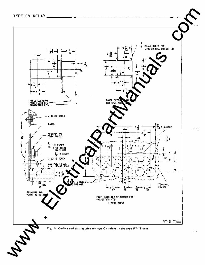
57-D-7900 Fi g. 14 Outline and drilling plan f t or ype C V relays in the type F T- 1 1 case.
www . El
ectric
alPar
tMan
uals
. com

www . El
ectric
alPar
tMan
uals
. com
W E S T I N G H O U S E E L E C T R I C C O R P O R A T I O N R E LAY - I N STR U M E N T D I V I S I 0 N N EWA R K , N . J.
Printed i n U .S .A. www . El
ectric
alPar
tMan
uals
. com
I N S T A L L A TI O N Westinghouse I . L . 41-2D l .2A
• O P E R A T I O N • M A I N TEN A N C E
INSTRUC T I ON S TYPE CV FREQUENCY
COMPENSATED VOLTAGE RELAY
C A U T I O N : Before putting rel ays into service, re
move all blocking w hich m ay have been inserted for
the p urpo se of securing the parts during shipm ent,
m ake sure that all moving p arts op erate fr eely, in
spect the contacts to s e e that t he y are cl ean and
op erate the relay to check the s ettings and elec
trical connectio ns.
A P P L I C A T I O N
The type CV relays are single-p hase induction
disc type relays operating either on under or over
voltage or both. These rel ays are frequency com
p e nsated such that their pickup between 30 and 90
cycles is within 5 per c ent o f the 60 cycl e value.
C O N T E N T S
This instruction leaflet applies to the following
typ es of relay s .
CV- 2 1 L o n g Tim e Undervoltage Relay
CV- 2 2 Short Time Undervoltage Relay
CV- 24 Long Time Overvoltage Relay
CV- 25 Short Time O vervoltage Relay
CV- 26 Long Time Over or Und ervoltage Relay
CV- 2 7 Short Time O ver or Undervoltage Relay .
C O N S T R U C T I O N & O P E R A T I O N
* The typ e s CV- 2 1 , CV- 2 2 , CV- 24, CV- 2 5 , CV- 26,
and CV- 27 relays consist of a voltage unit and an
indicating cont actor s witch ( ICS). The comp on ent
parts of the relays are connected as shown in the
internal schematic diagram . Som e styl e relays con
tain an inst antaneous indicating voltage switch
( IIV) w hich also op erates independ ent of frequency.
A. Vol tage Un i t (CV)
The o vervoltage unit is an "E" typ e laminated
structure with coil s on each leg. The coil on t he
center l e g of the structure is an autotransformer,
SUPERSEDES I . L . 4 1-20 1 . 2 * Denotes change from superseded i ssue.
winding w i t h a tapp ed p rimary. The se condary
winding of the autotransfo rm er is connected to
identical coils on the o uter legs of the "E" typ e
l aminated structure. The coil s are connected in
such a manner that the combination of all the fl uxes
p roduced result in out- o f-phase fl uxes in the air gap. The out- of-phase air gap fluxes produced cause a
contact closing torque.
The undervoltage unit op erates on the same
principle as the overvoltage unit except t he con
nections to the l eg coils are reversed to cause the
o ut- o f-p hase fl uxes to produce a contact opening
torque.
The units are frequency comp en sated by means
of a resistor located in the outer l e g coil circuit.
The instantan eous trip unit is a s m all a- c oper-
* ated clapp er typ e device. A m agnetic arm atur e , to
w hich leaf-spring mounted cont act s are attached , is
attracted to the magnetic core upon energization of
t he s witch. When t he s witch closes, t he moving con
tacts bridge two stati onary contacts c ompl eting the
trip circuit. Also during t he operation two fi ngers on
the armature defl ect a spring located on t he front of
the switch w hich allow s the op eration indicator
target to drop. The target is reset from the outside
of the case by a push rod lo cated at the bottom of
the cover.
The adjustable pickup range is accomplished by
m eans of an adj ustable resistor.
C. Indicat ing Contactor Switch ( ICS)
The indicating contactor switch i s a small d-e
op erated clapper typ e d evice. A m agnetic arm ature,
to which leaf- spring mo unted contacts are attached ,
is attracted to the magnetic core upon energization
of the switch. When the switch clo s e s , the moving
contacts bridge two s tationary contacts, compl eting
the trip circuit. Al so , during t his operation t wo
E F FECTIVE OCTOBER 1967 www . El
ectric
alPar
tMan
uals
. com
TYP E CV R ELAY ________________________________________________ _
I I IICATING C ITACTOR SWI TCH
COIITACT POS I T I ON RELAY OE-EMERG IZED OYER·YOLTAG£ - OPEN UIIDER-VOL TAG£-CLOS£0
IIIOUCTION UN I T
INDUCTION UJI I T
LAG CO ILS
RED HANDLE
lEST SWITCH
TERMUIAL
185Al33 Fig. 7 Internal Schematic for the type C V (S. P . S. T. )
voltage relay in the F T- 1 7 case.
fingers on t he armature defl ect a spring l ocated on
front of the switc h , which allows the operation in
dicator target to drop. The target is reset fro m t he
outside of t he case by a push rod located at the
bottom o f the case.
The front spring , in addition to holding the
target , p ro vides restraint for the armature and thus
controls the pickup value o f the s witch.
C H A R A C T E R I S T I C S * These relays are frequency co mp ensated such t hat
their pickup between 30 and 9 0 cycles is within 5%
of the 60 cycle value.
The CV-2 1 and CV- 22 undervoltage relays, CV- 24
and CV- 25 o vervoltage relay s , and CV- 26 and CV- 27
over or undervoltage rel ays are available in the
voltage ranges:
Range Tap s
5 5- 1 4 0 5 5 6 4 7 0 8 2 93 1 05
1 10- 280 1 10 1 2 8 1 40 1 6 4 1 8 6 2 1 0
A. CV-2 1 and CV-22 Undervo l tage Rel ays CV-24 and CV-25 Overvoltage Rel ays .
1 20 1 40
240 280
Tap value voltage i s the m inimum voltage r e
quired to just clo s e the relay contact s . A t this
value o f voltage, the moving contacts will leave
the back stop of the time dial and move to clo s e the
2
*
UIOICATING ------.._______ COJITACTOR SWITCH -
Ci»>TACT POS I T IONS RELAY DE-ENERG IZED OYER-VOLTAGE - OPEN UNDER-VOLTAGE-CLOSED
ED HANDLE
TEST SWI TC'ft
TERMINAL
185Al34 Fig. 2 Internal Schematic for the type C V (D . P . S. T. )
voltage relay in the F T- 7 7 case.
front contacts. Normal op eration of the two relays
is such that the C V- 2 1 and CV- 2 2 undervoltag e
relays will open its contacts with app lication of
voltages greater than tap v alue voltag e , while the
CV- 24 and CV- 25 overvoltage relay clo ses its con
tacts with voltages greater than t ap value voltage.
B. CV-26 and CV-27 Over or Undervol tage Relays
Tap value voltage i s the value o f voltage at
which t he stationary front contact clos e s . The
stationary b ack contact will close within 5% of this
value.
When the relay is used as an overvoltage relay ,
t h e moving contact i s m ade w i t h the stationary back
co ntact for values o f applied voltage l es s than tap
value v oltage. Wit h application of voltag e s great ei
t han tap value voltage, the moving c ontact moves t o
close the front cont act i n a t i m e as s hown by the
right hand curve o f either Fig. 8 or 9.
When the relay is used as an undervolt ag e r el ay,
t he moving cont act is m ade with the stationary front
contact for values of app l ied vo ltag e great er than t ap
value voltage. With the application of voltages l e s s
than tap value voltage, the moving contact m o v e s t o
close t h e b ack contact i n a t i m e a s s h o w n on t h e
l eft-hand curves of either fi gures 8 or 9.
www . El
ectric
alPar
tMan
uals
. com
TYPE CV RELAY------------------------------------------------�'�-L�.4�1�-2�01�.2�A
Rat ed T A P S
-
Voltage 1 20 Volt Relay 240 Volt Relay
5 5 1 1 0
64 1 28
7 0 1 40
8 2 1 64 1 20 o r
2 4 0 Volts
93 1 86
1 0 5 2 1 0
1 20 240
1 40 280
* C. In stantaneou s Indi cati ng Vol tage Swi tch (I I V)
*
The range of operation is 1 20 to 200 volts ac. The
pickup is adj usted by means of an adj ustable resis
tor.
Tri p C i rcu i t
T h e m ain contacts will s afely close 3 0 amp eres
at 250 volts d- e and the seal- in contacts of the
indicating contactor switch will safely carry this
curr ent long enough to trip a circuit breaker.
The indicating cont actor switch has two tap s
that provide a pickup setting of 0 . 2 or 2 amp eres. To
change tap s requires co nnecting the lead lo cated in
fro nt of the tap block to the de sired s etting by means
of a screw co nnection.
Tri p C i rcu i t Constants
Indic ating co ntactor - 0 . 2 Amp . tap 6 . 5 ohms d- e Switch resi stance
0 . 2 Amp . tap 0 . 1 5 o hms d- e
resi stance
E N E R G Y R E Q U I R E M E N T S
The burdens o f the CV-2 1 , CV- 2 2 , CV- 2 4 , CV- 2 5 ,
CV- 2 6 , CV- 2 7 relays at rated voltage are a s follows
The b urden of the 1 1 V ( when used) is in addition
to the above burdens and is as follow s :
setting - ----
1 20 Volts
200 Volts
Voltage App lied -- -- ----
1 20 Volts
200 Volts
Burden
2 . 0 VA.
3 . 0 VA.
Power Volt-Amp s . Watts
F actor
1 4 . 3 8 . 44 6. 3
1 0 . 3 8 . 4 1 4 . 23
8 . 3 5 . 3 9 3 . 26
6 . 00 . 3 7 2 . 23
4 . 6 6 . 35 1 . 63
3 . 64 . 34 1 . 25
2 . 7 7 . 3 3 . 9 2
2 . 0 4 . 3 1 . 63
S E T T I N G S
A. CV Un i t
T h e setting o f t h e CV unit can b e defined either
by tap setting and time dial po sition or by tap set
ting and a specific time of op eration at some p er
centage of tap value voltage ( e . g. o n CV- 24 1 20 tap
settin g , 2 time dial po sition or 1 20 tap setting, 1 2
seconds at 1 40 per cent o f tap value voltage ) .
T o p rovide sel ective circuit breaker op eration ,
a minimum coordinating time o f 0 . 3 seconds plus
circuit breaker time is r ecommended b etween the
relay b eing set and the relays with w hich coordina
tion i s to be effected.
The connector screw on the terminal plate above
the time dial connects v arious turns of t he operating
coil. By placing t his screw in the various terminal
plate holes , the relay will just close its co ntacts at
the corresponding voltage of 5 5- 64- 7 0- 8 2- 9 3- 1 0 5- 1 20-
1 50 volts or as marked on the terminal plat e .
T he nylon screw o n the terminal plate holds the
tap plate in po sition when tap s are being c hanged.
To use the po sition o n the terminal plate in which
the nylon screw is used, remove the nylon screw and
place it in one of the unused holes. T hen remo ve the
tap screw and insert it in the terminal plate hol e .
I n stantaneous Rec los ing
T he factory adj ustment of the volt age unit con
tacts provides a contact follow. Where circuit break
er reclosing will be i nitiated immediately after a
3 www . El
ectric
alPar
tMan
uals
. com
TYP E CV R ELAY ______________________________________________ ___
LEFT HAND CONTACT ( FRONT V I EW )
/ R I GHT HAJID CONTACT (FROMT YlfW)
IMDICATIIG COIHACTOR SWITCH
INTERNAL SCHEMATIC
ED HAIIDLE
TEST SWI TCH
TERMIIIAL
185Al35 Fig. 3 Intern a l Schematic for the type CV (S. P. D. T. )
voltage relay in the F T- 1 1 case.
trip by the o vervoltage contact , the time of the
op ening of the contacts should be a minimum. This
condition is obtained by loos ening the s tationary
contact mounting scr e w , removi n g the contact pl ate
and then r eplacing the plate with the bent end rest
ing against the co ntact spring.
For double trip relay s , the upper statio nary con
tact is adj usted such that the contact rests solidly
against the b ack stop . The lower stationary con
tact is then adjusted such that both stationary con
tacts m ak e contact sim ultaneously with their res
pective moving cont act.
* B . In stantaneous Ind icat ing Voltage Switch ( I IV)
T h e adj ustabl e resistor m ust be adj usted for t h e
desired pickup voltag e .
C. I nd i cat ing Contactor Switc:� ( IC�
Only one setting i s required on the res unit;
that i s , the sel ection of the 0 . 2 to 2 . 0 amp ere tap
setting. This s el ection is m ad e by connecting the
l e ad located in front o f the tap block to the desired
setting by m eans of the connecting screw.
I N S T A L L A T I O N
The relays should be mo unted on switchboard
panels or their equivalent in a lo cation free from
dirt , moistur e , excessive vibration, and heat . Mount
4
the relay vertically by means o f the four mounting
holes on the flange for semi-flush mo unting or by
m eans o f the r e ar mo unting stud o r studs for pro
j ection mountin g . Either a mounting s tud or the
mo unting screws m ay be utilized for grounding the
relay. The electrical connections may be m ade dir
ectly to the terminal s by means o f screws for steel
panel mo unting or to the terminal studs furnished
with the relay for thick panel mounting . The ter
minal studs may be e asily removed or ins erted by
locking two nuts on the stud and then turning the
the proper nut with a wrench.
For detailed FT Case information refer to I . L .
4 1- 0 7 6 .
A D J U S T M E N T S & M A I N T E N A N C E
The proper adj ustments to i nsure correct opera
tion o f this relay h ave b een m ade at the factory.
Upon receipt o f the relay, no customer adjustment s ,
other than tho s e covered under "Settin g s , " should
be required.
Acceptance Check
The following c heck is recomm ended to insure
that the relay i s in prop er working o rder:
A. CV Un i t
1 . Contact
The index m ark on t he movement frame will
coincide with the "0" mark on the time dial
when the stationary contact has moved
through approximately one h alf of its normal
deflection. Therefore , w ith the stationary
contact re sting agai nst the back stop , the
index m ark is offset to the right of the "0" mark by approximately . 0 2 0 " . (For t h e typ e
CV- 2 6 and CV- 27 rel ays the b ack cont act has
no follow when the front contact is thro u gh
one-half of its follow). The p l acem ent of the
various time dial po sitio ns in line with the
index m ark will give op erating times as
s ho wn on the r e sp ective time- c urrent curves.
For double trip relay s , the follow o n the
stationary contacts s ho uld be approximately
1 / 3 2 " .
2 . Minimum Trip Voltage - s e t t h e time dial to
po sition 6. Alternately apply tap value volt
age plus 3% and tap value voltage minus 3%.
a. CV-24 and CV- 25 Ov ervoltage Rel ays ,
www . El
ectric
alPar
tMan
uals
. com
TYPE CV R ELAY----------------------------------------------------��·�L .�4�1 -�20�1�.2A
CV- 2 6 and CV- 27 Over or Undervoltage
Relays - The m oving c ontact should
l e av e the back stop at tap value voltage
plus 3% and should return t o the back
stop at tap value voltage minus 3%
b. CV- 2 1 and CV- 2 2 Undervoltage Relays -
The moving cont act s ho uld leave t he
b ack stop at t ap value voltage minus 3%
and should return to the b ackstop at tap
value voltage plus 3%.
* 3. In stantaneous Indicating Voltage Switch (11V) Apply de sired pi ckup voltage and adj ust the
internal adj ustable resi stor until the con
tacts j ust m ake. The t arget s hould drop
freely.
4 . Indic ating Contactor Switch ( ICS) - Clo se
the m ain relay c ontacts and p ass sufficient
d-e current t hrough the trip circuit to close
the contacts o f t he res . This v alue of cur
rent should be not gr eater t han the particular
ICS tap setting being used. The op eration
indicator target should drop freely.
The contact gap should be approximately
. 047" b etween the bridging moving co ntact
and the adjustable stationary contacts. The
bridging moving could touch both stationary
contact s simultaneously.
Routing Maintenance
All relays should b e inspected periodically
and the time of op eration should be checked at
least once every year or at such other time interval s
a s may b e dictated by e xperience to be suitable to
the particular application. T he use of phantom load s,
in testing induction- typ e relay s , should b e avoided ,
since t h e resulting di storted current wave form will
produce an error in timing.
All contacts should be p eriodically cleaned. A
contact burnisher # 1 82A836H0 1 i s recomm ended for
this purp o s e . The use of abrasive material for clean
ing contacts i s not recommended, b ecause of the
danger of embedding s mall p articl es in the face of
the soft filver and thu s , impairing the contact.
Cal ibration
U s e the following procedure for calibrating the
relay if t he relay has been taken apart for rep airs ,
or the adjustm ents have been distrubed. This proce
dure should not be used until it is app arent that the
relay is not in proper working order (See "Accept
anc e check " )
A. CV Un i t
1 . Contact
The index m ark on the movement frame will
coincide with the " 0 " m ark on the time dial
when the stationary contact h as moved
through approximately one h alf of its norm al
deflection. Therefore , with the stationary
contact resting against the b ackstop, the
index mark is offs et to the right of the " 0 " m ark by approximately . 0 20 " . ( F o r t h e type
cv- 26 and cv- 27 relays t h e b ack contact has
no follow w hen t he front contact is t hrough
o ne- half of its follow). T he placement of the
various time dial po sitions in line with the
index m ark will give operating times as
s hown on the respective time- current curves.
For double trip r elays, the follow on the
stationary contacts s hould b e approximately
1 / 3 2 " .
2 . Minimum Trip Voltage
The adjustment o f t he spring tension in
setting the minimum trip voltage v alue of the
relay is most conveniently made with the
damping m agnet removed .
Set the relay o n the minimum tap s etting.
Adjust the spring s uch that the s ame voltage
is required to j ust move the contact from the
back stop of the time dial to the Vz and 1 0%
position.
Set the relay on the 6 time po sitio n .
a. CV- 24 and CV- 25 Overvoltage, CV- 26
and cv- 27 Over or Undervoltage - Adjust
the r esistor in t he rear so that the moving
contact will l eave the b ack stop of the
time dial at t ap value v oltage + 1 . 0% and
will return to the backstop at tap value
voltage - 1 . 0%.
b. CV- 2 1 and CV- 2 2 Undervoltage Relays -
Adjust the resistor in the rear so that the
moving contact will leave the backstop of
the time dial at tap value voltage - 1 . 0%
and will return to the b ackstop at tap
value voltage + 1 . 0%.
3 . Install the perman ent m agnet.
a . CV- 2 1 and CV- 2 2 Undervoltage Relay -
U s e designated test circuit . With switch
"S" opened, adjust resistor " A " until
voltmeter reads tap value voltage or
higher . Close s witch " S " and adjust
re sistor "B" until the voltmeter read s
5 www . El
ectric
alPar
tMan
uals
. com
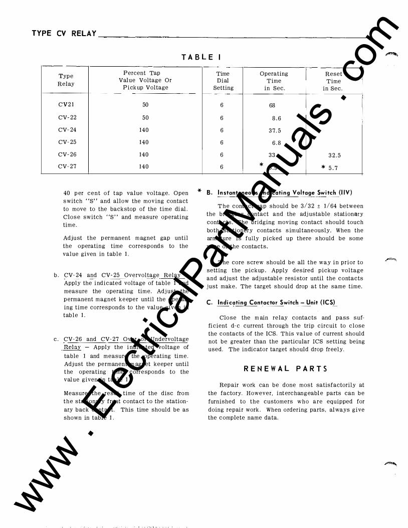
TYPE CV RELAY ________________________________________________ _
6
T A B L E I
Typ e P ercent Tap
Relay Value Voltage Or
P i ck up Voltage
C V 2 1 50
CV- 22 50
CV- 24 140
CV- 25 140
CV- 26 140
CV- 27 1 4 0
40 p er c e n t o f t ap value voltage. Open
s witch "S" and allow the moving contact
to move to the back stop of the time di al .
Clo s e switch "S " and m easure op erating
time.
Adju st the p er m anent m agnet gap until
the operatin g time correspond s to the
value given in table 1 .
b . CV- 24 and CV- 25 Overvoltage Relay -
Apply the i ndicated voltage of table 1 and
measure the operating tim e . Adj ust the
p ermanent m agnet k e eper until the operat
ing time corresponds to the value given in
table 1 .
c . CV- 26 and CV- 27 Over o r Undervolt age
Relay - Apply the i ndicated voltage of
table 1 and m easure the operating ti m e .
Adj ust the permanent m agnet keeper until
t he operating time corr e sponds to the
value given in table 1 .
Measure the reset time of the disc fro m
t h e stationary front contact t o the station
ary b ack cont act. This time should be as
shown in table 1 .
Time Operating Reset Dial Time Time
Setting in Sec. in Sec.
6 68
6 8 . 6
6 3 7 . 5
6 6 . 8
6 3 3 3 2 . 5
6 * : 5 . 9 * 5 . 7
* B . I n stantaneous Ind i cati ng Vol tage Swi tch ( I IV )
T h e cont act gap should be 3 / 3 2 ± 1 / 64 between
the bridging contact and the adj ustable stationary
contacts. The bridging moving co ntact should touch
bo th stationery contacts s imultane ously. When the
arm ature is fully picked up there s hould b e some
wipe of the contact s.
The core s crew should b e all the way i n prior to
setting the pickup . Apply desired pickup voltage
and adjust the adj ustabl e resi stor until the c o ntacts
just mak e . The target should drop at t he same time.
C. Ind i cati ng Contactor Switch - Unit ( ICS)
Clo se the m ain relay contacts and pass suf
fi cient d- e current through the trip circuit to close
the contacts of the res. This value of current should
not b e greater than the particular res setting being
used. The indicator target should drop fr eely.
R E N E W A L P A R T S
Rep air work can b e done most satisfactorily at
the factory. However, i nt erchan g eabl e parts can b e
furnished to t h e customers w h o a r e equipped for
doing repair work . When o rdering parts , al ways give
the complete name data.
www . El
ectric
alPar
tMan
uals
. com
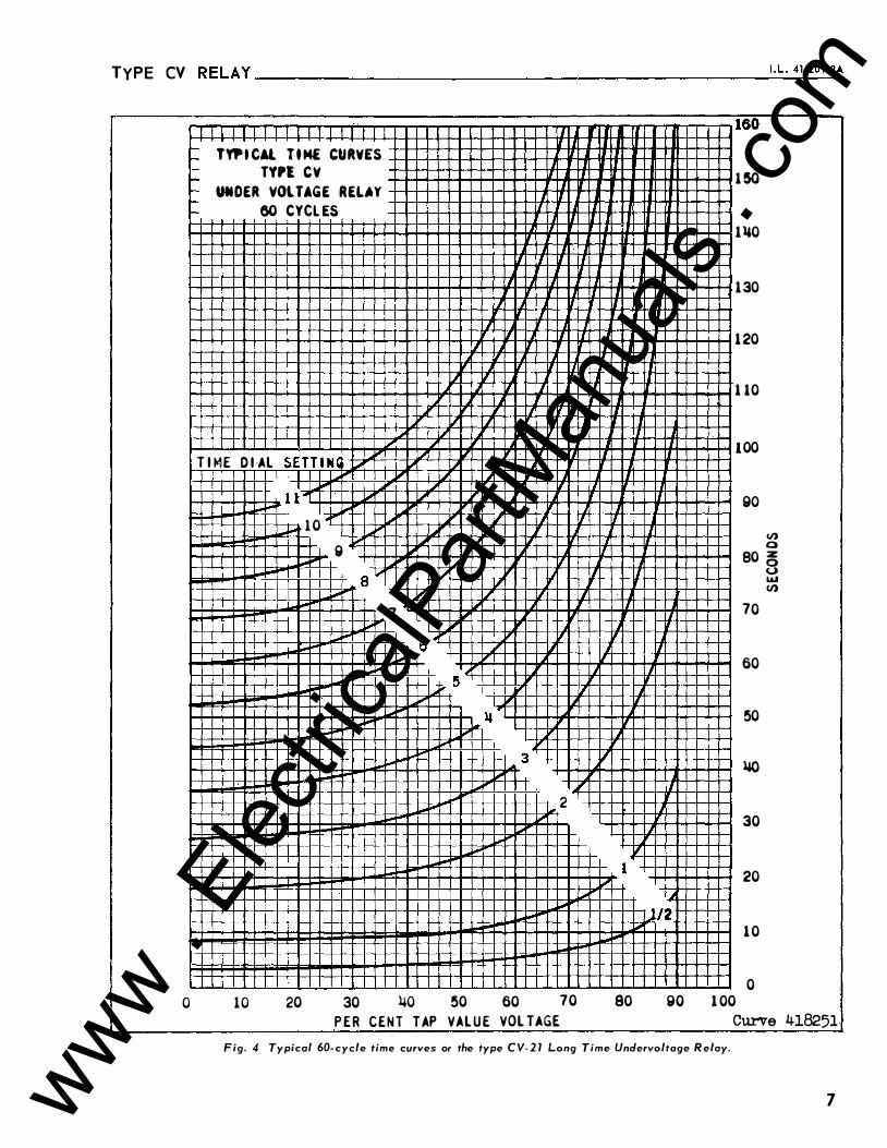
TYPE CV R ELAY --------------------------------------------------�I . L�·-4_1 -�20_l .�2A
I
11 1 11 1 11 11 I I I I I � TYP I CAl T t M£ CURVES � - TYPl CY � f-- UNDER VOlTAGE RELAY r- 60 CYCL ES f--
v T I ME
0
O I ·AL SEll i N (
10
_I I I I 1 1..,.. ....
"'
_ ... 1 0 .. g
....
...
....
1--
1-1-'
20
!." ""
� ,. �
8�
7 ...
...
... l..o
I,..
30 ltO
1..1'
/
6
,.
l..o
P ER CENT TAP
J
1.1' ljl 1/ WI' 1/ I�
[/
[,I
1/ � ., "
' � 5
�... ll ""
J...,. j,.o
"""
loool-'
50 VAL U E
r1 r 1 160
1 50
1 II 1 rT 1 ll0
I rT if 1 30
IJ II II l I I 1 20
7 II if 1 10 I ' II rT II
'T rJ rT IT 100
if IT go
/ J 7 IT I II) 0 80 �
IT rT <.,) , 1&1 1/ (J)
IT 70 � i
V' ., � I J , / 60
7' 'T 50
3 ljl lW """ r1
2 l J...,. IJ 30
J.,.. 1 20 J,;;;ii
,_, j,.o l/2 � ""' 1 0 '-""" L-0
60 70 80 go 1 00 VOLTAGE Curve
Fig. 4 Typical 60- cycle time curves or the type CV- 2 1 Long Time Undervoltage R elay.
'
418251
7 www . El
ectric
alPar
tMan
uals
. com
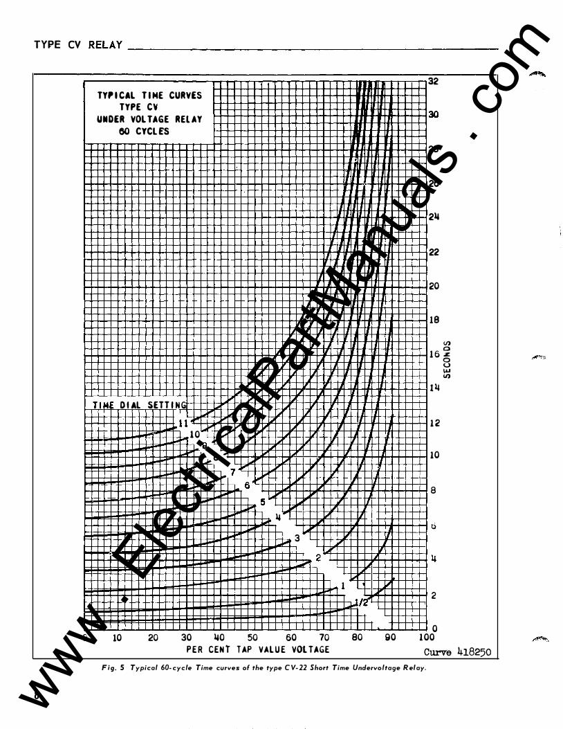
TYPE CV R ELAY-------------------------
0
8
TY, I CAL T I ME CURVES
TYPE CY UNDER VOL TAGE REl AY
60 CYCL ES
'
.
II ILLl
II J
lL
llll II '# II
lL l1 11 11 II
II II J _1 ll_
II II II II I J If , If II II � L1 11 IJ v
1,; v lL u JL lL T l tot D IAL SETTIN G
,.,. � I..- , u I J..oo � IJ II I J II I
J..loo l l ,.. " J...- L..l !I I � v 1.' v II loorr"' 10 """ " l...- v L1 looo 9 ....
�-� 8 ... " J � 7 .,... 'I .... . 6 " 'L ll """ � .... ""' l..or 5 " II �-� � ""' IL ""' lJ � IL
""" 3 , � ,., . 2 io"" � 1
'r!JI� . I I
_l j_ I
10 20 30 lJO 50 60 70 80
P E R CEN t TAP VAL U E VOL TAGE
lJ
I I '1
I .
II ,
�
90
32
30
28
26
216
22
20
18
en
1 6 � 0
t lJ
1 2
10
8
0
2
0 1 00
u � en
Curv-e 418250 Fig. 5 Typical 60- cycle Time curves of the type C V- 22 Short Time Unclervoltage R elay.
""""""""
l!!l!fi�;JI'f�
www . El
ectric
alPar
tMan
uals
. com
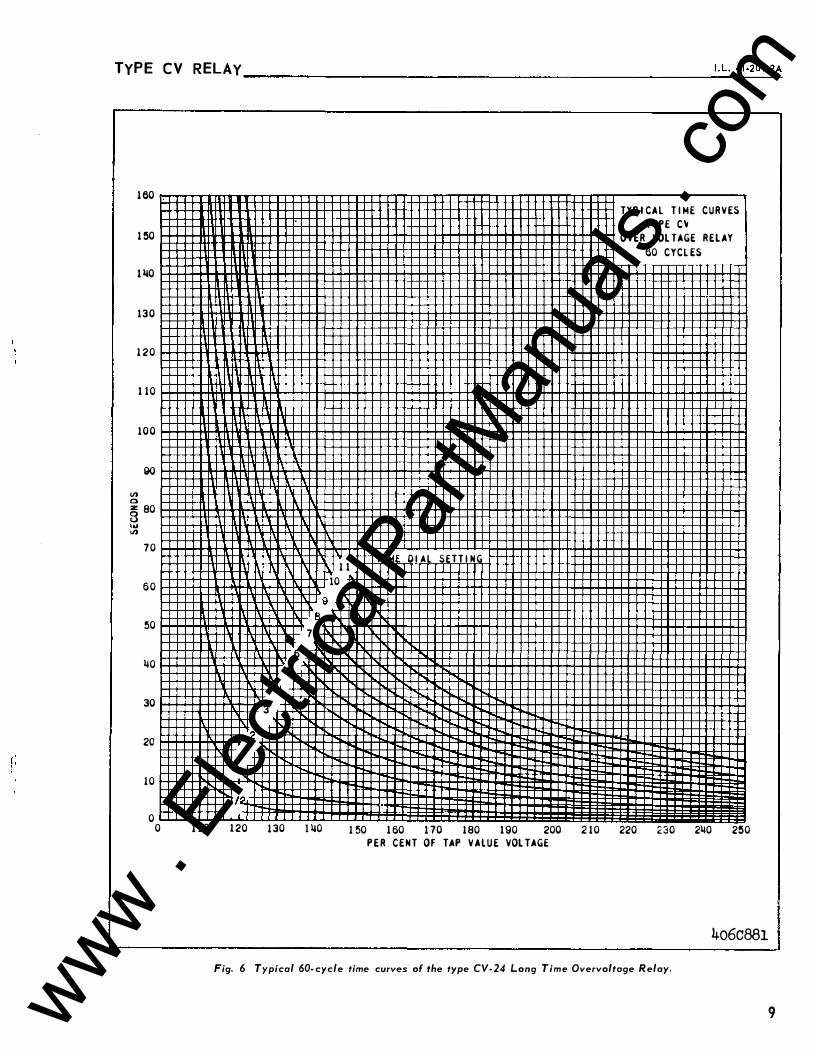
! :
TYP E C V RELAY ____________________________________________________ I . L_. _4 1_·2_o_L_2A
1 60
1 �0
1 140
130
120
1 10
1 0 0
90 VI a z 80 8 .... VI
70
60
50
140
30
20
10
0 0
B
7
6
� 14
3
2 IS
1 <;[ 9;�
110 120 130 1 140
9
TYP I CA L T I ME C U R V ES
TYPE C �
OVER VOL TAGE R E L AY
60 CYCL ES
.
1 1 T IME O I A L SETT I N G
10
.
1 50 1 60 1 70 180 1 90 200 210 220 230 2140 2�0 P E R C E N T OF TAP V A L U E VOL TAGE
4o6c881 Fig. 6 Typical 60- cycle time curves of the type CV- 24 Long Time Overvoltage Relay.
9 www . El
ectric
alPar
tMan
uals
. com
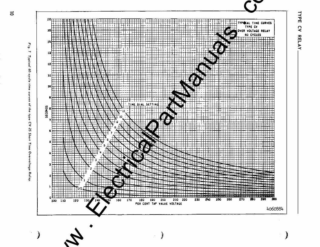
-0
::!) '!l ...... -1 "< 1J n 2.. 0\ c;:> n "< n j) ... 3" ID n c: ., '( ID Ill 0 ..... ... :I" ID � ID () -::=: "' tl1 "' :I" 0 :::. -1 3" ID 0 '( ID ., '( 0 Q IQ ID ::0 � c ;<
)
1'6"
i )15
Jll I
li i
12 !
u I �· tO' i
<n Q � 8 ... <n ., i
5
"
3 ' 1!
�
0
14 3
2
1
1/2
I IV\ 1 t n t '> n t '!>n l im
T I ME D I AL SETT I H 11
10
II 8
7 6
!l
ll'in t An 170 IRQ IQO 200 2 10 220 PER CENT TAP VALUE VOLTA(iE
) ,.#'
TYP I
OV£11
230 2l&O 2!50 260 70
CAL T I M£ CURVES
TYI'£ CV
VOLTAii£ RELAY
60 CYCL£S
210 HO 304 4o6c884
)
-t -< -o m n < ;;o m r > -<
www . El
ectric
alPar
tMan
uals
. com
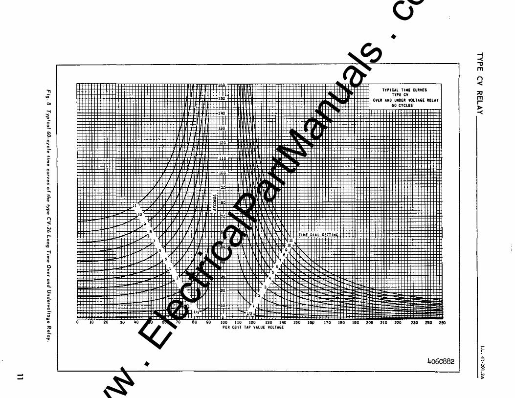
., �-co
..... '< , n !!... 0.. � n '< !!. ID ... 3" ID n c: ., < ID .. 0 .... ;. ID � , ID I") ..;: t... 0.. r-0 :I IQ -t I 3" ID f l Q :I a.. I c: :I a.. ID �
f l "' ID Q �
--
II I I I·�· 1 1 1 1 1 1 I 1 1 1H1TI I I I I I IM1 1 1 1 1 e
1 1 1 1 1 1 1 1 1 1 1 1 tmrnmftiDUHl� . 3
I I I I I I fll I I I I I I I I I I I I I I U I'Offl I I I I I I l 2
II l l l l l l l l l l l l l l l l l l l l l l l l l l ll l l l l l l l l l l :'121 0 10 20 ao 110 !SO 60 70 eo so
I �
i 1 110
I! 130
m 120
m 1 10
m 100
I V) 0 3Hao ... V) ..-W-J 70
�0
0
10
Jo
3
2
/2
II
6 �
7
11 10 Q
8
T I ME D I A L SETT I N
TY P I CAL T I ME CURY£5 TYPE CY
OYER AND UNDER VOLTA&£ RELAY
00 CYCLES
100 1 10 120 130 1 110 1!10 l&p 170 180 ISO 200 210 220 230 2110 2!10 P E R CEtH TAP VALUE VOLTAGE
4o6c882
-i -< '"'IJ m n < :::0 m r > -<
r ""' ;, 0 ..., >
www . El
ectric
alPar
tMan
uals
. com
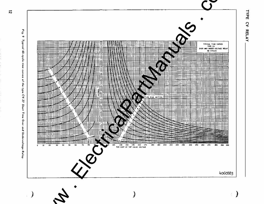
-N
"11 '!l '() ..... "< "'J n 2.. a.. ? n "< n iD ... i f1) n !; < f1) Ill 0 ..... ... ::r-11)
� f1) (') -:::: N � "' ::r-0 :::. ..... 3" f1) 0 < � § 0.. c: " � .. < � Q IQ f1) :::0 f1) Q ':"
10 20 30 �0 �0 60 70
)
I �
I �
1/2� l
1112 I I I II I II II I II if I II I I I I I BO go 100 1 10 120 130 1�0 1 �0 160 170 180 190 200 210 220 230
PER CENT OF UP VALUE VOlTAGE
) 11'
TYPI CAL T l NE CUR YES
TYPE CY
OYER AIID UNDU YOL UGE RELAY 80 CYCLES
2� 280 260 270 2BO 2go 3oo
4o6c883
)
-f -< "tt m n < :::0 m r )>--<
www . El
ectric
alPar
tMan
uals
. com
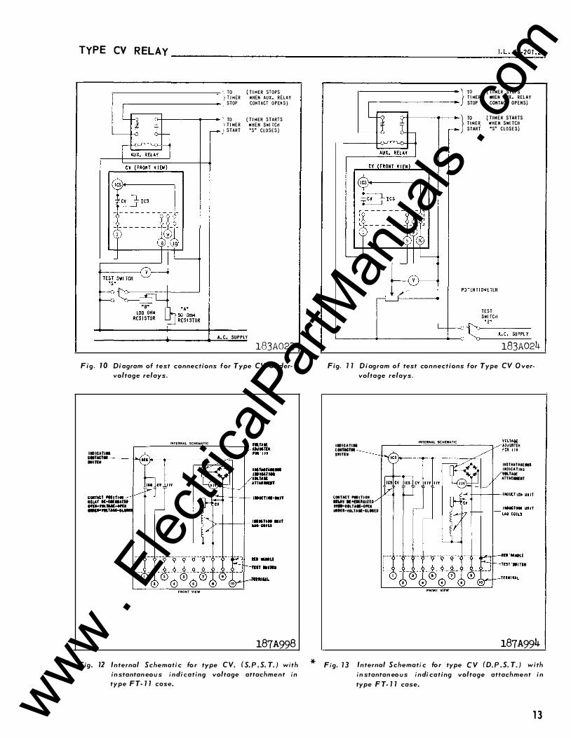
*
TYPE CV R ELAY J . L . 41 -2D1 .2A ------------------------------------------------------���
• TO ( T I MER STOPS I T i MER WHEH AUX, RElAY STOP CONTACT OPEN S )
' TO ( T I MER STARTS \ T I MER WHEN SWI TCH
) START "S" CLOSES )
A. C. SUPPLY 183A023
Fig. 10 Di agram of test connections for Type CV Un dervoltage relays.
INTERNAL SCHEMATIC
I., ICATIM ctiTACT. ----4->o./ •• Tell
FRONT VIEW
187A998 Fig. 12 Internal Schemati c fo r type CV. (S. P . S. T. ) with
in stantan eou s indi eating voltage attachment in type FT- 1 1 case.
*
ro ( Tl MER STOPS TI MER WHEH AUX, RELAY STOP CONTACT OPENS)
ro ( TIMER STARTS TIMER •HEH SWI TCH START "S" CLOSES)
TEST SWI TCri
�--------�-----------------4---o i:::�-· s_" __ A_.-c.--su-P-PL_Y_
183A024 Fig. 1 1 Diagram of test connections for Type CV O ver
voltage relays.
I.ICATIII COIITKTOI SWITCII
COITACT ,.JTIOIII 11"' ·n•nuaozto 0111-IILTA··OPEI UIHI-WOLTAGI·CLISED
INTERNAL SCHEMATIC
IIISTANTAIEtiiS IJIDICATJIG VIllA&£ AITAC-IT
187A994 Fig. 1 3 Internal Schemati c fo r type C V (D. P . S. T. ) with
in stantan eo us indi cating voltage attachment in type F T- 1 1 case.
13 www . El
ectric
alPar
tMan
uals
. com
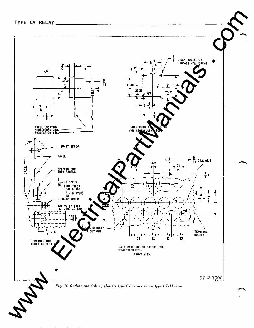
TYPE CV R ELAY
14
--------
- I • ....
-f
�II
6 1 1 I I 6 i
�·
PANEL LOCATI 011 SEMI-FLUSH MTG· PROJECTION MTG.------_j
PANEL
SPACERS FOil THIN PAIIELS
5 j6 1 8 SCI!EW ( FOI! THICK PANEL USE L 1 s STUD) 1 6 . 1 90-32 SCitEW
9 Ts
3 'i 0 1 1 .. 1 0 HOLES 01! CUT OUT TERM INAL AIID MOUNTI NG DETA I LS
I -r 5 ! 1 r 'i .DI A.II MOLES FOR
7 �1- .f }'_ . 1 .... 32 MTG; SC"W!
+ t -I.,..
PANEL CUTOUT & DR I LLI•G FOR SEMI-FLUSH MTG.
�:��C��b�L��g,o�t
CUTOUT FOI!
( FRONT V I EW)
s l 8 3 - I! �
TE""' INAL NUMBER
57-D-7900 Fig. 14 O ut/ in e ancl cl ·tt · I rr rng p an for type CV I . re ays rn the type F T- 1 1 case.
www . El
ectric
alPar
tMan
uals
. com

www . El
ectric
alPar
tMan
uals
. com

W E S T I N G H O U S E E L E C T R I C C O R P O R A T I O N R E LAY- I N ST R U M E N T D I VI S I O N N EWA R K , N . J.
Printed in U.S .A . www . El
ectric
alPar
tMan
uals
. com
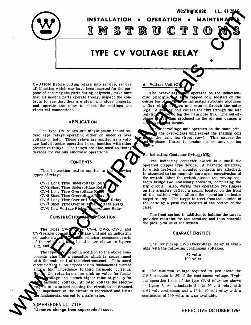
Westinghouse I . L. 41 -20 1 G INSTALLATION • OPERATION • MAINTENANCE
INSTRUCTIONS TYPE CV VOLTAGE RELAY
C AU T I O N Before putting relays into service , remove all blocking which may have been inserted for the purpose of securing the parts during shipment , make sure that all moving parts operate freely, inspect the contacts to see that they are clean and close properly, and operate the relay to check the settings and electrical connections.
APP LICATI ON
The type CV relays are single-phase inductiondisc type relays operating either on under or over voltage or both. These relays are applied as a voltage fault detector operating in conjunction with other protective relays. The relays are also used as timing devices for various automatic operations.
CONTENTS
This instruction leaflet applies to the following types of relays:
CV- 1 Long Time Undervoltage Relay CV-2 Short Time Undervoltage Relay CV-4 Long Till'e Overvoltage Relay CV-5 Short Time Overvoltage Relay CV-6 Long Time Over or Undervoltage Relay CV-7 Short Time Over or Under voltage Relay CV-8 Low Voltage Pickup Overvoltage Relay
CONSTR UCTION AND OPERATION
The types CV- 1 . CV-2, CV-4, CV-5, CV-6, and CV-7 relays consist of a voltage unit and an indicating contactor switch (ICS). The principal component parts of the relay and their loc ation are shown in figures 1 , 2, and 3.
The type CV-8 relay in addition to the above components also has a capacitor which is series tuned with the main coil of the electromagnet. This tuned circuit offers a low impedanc e to fundamental current and a high impedance to third harmonic currents. Hence, the relay has a low pick up value for fundamental voltage and a much higher value of pickup for third harmonic voltage. At rated voltage the electromagnet is saturated causing the circuit to be detuned. The impedance of the circuit is increased and limits the fundamental current to a safe value.
SUP ERSEDES I. L. 20 1 F *Denotes change from superseded i ssue.
A. Voltage Unit (CV) The overvoltage unit operates on the induction
di sc principle. A main tapped coil located on the center leg of an "E" type laminated structure produces a flux which divides and returns tlrough the outer legs. A shading coil causes the flux through the left leg (front view) to lag the main pole flux. The out-ofphase fluxes thus produced in the air gap causes a contact closing torque.
The undervoltage unit operates on the same principle as the overvoltage unit except the shading coil is on the right leg (front view). This causes the out-of-phase fluxes to produce a contact opening torque.
B. Indicating Contactor Switch (ICS)
The indicating contact6r switch is a small d-e operated clapper type device. A magnetic armature, to which leaf-gpring mounted contacts are attached, is attracted to the magnetic core upon energization of the switch. When the switch closes, the moving contacts bridge two stationary contacts, completing the trip circuit. Also , during this operation two fingers on the armature deflect a spring located on the front of the swi tch, which allows the operation indicator target to drop. The target is reset from the outside of the case by a push rod located at the bottom of the case.
The front spring, in addition to holding the target, provides restraint for the armature and thus controls the pickup value of the switch.
CHARACTERISTICS
The low pickup CV-8 Overvoltage Relay is available with the following continuous voltages.
67 volts 199 volts
* The minimum voltage required to just close the
CV-8 contacts is 8% of the continuous voltage. Typi
cal operating times of the type CV-8 relay are shown
on figure 8. An adjustable 5 . 4 to 20 volt relay with
a 67 volt continuous and a 1 6 to 40 volt relay with a
continuous of 199 volts is al so available.
E FFECTIVE OCTOBER 1 967 www . El
ectric
alPar
tMan
uals
. com
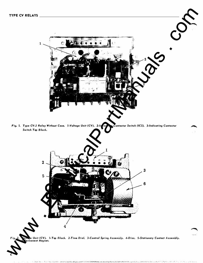
TYPE CV RELAYS
1
Fig. 1. Type CV-2 Relay Without Case. 1-Voltage Unit (CV). 2-lndicating Contactor Switch (ICS). 3-lndicating Contactor
Switch Tap B lo ck.
2
3
5
6
4
Fig. 2. Voltage Unit (CV). 1- Tap Block. 2- Time Dial. 3- Control Spring A ssembly. 4-Disc. 5-Stationary Contact A ssembly. 6-Permanent Magnet.
2 www . El
ectric
alPar
tMan
uals
. com
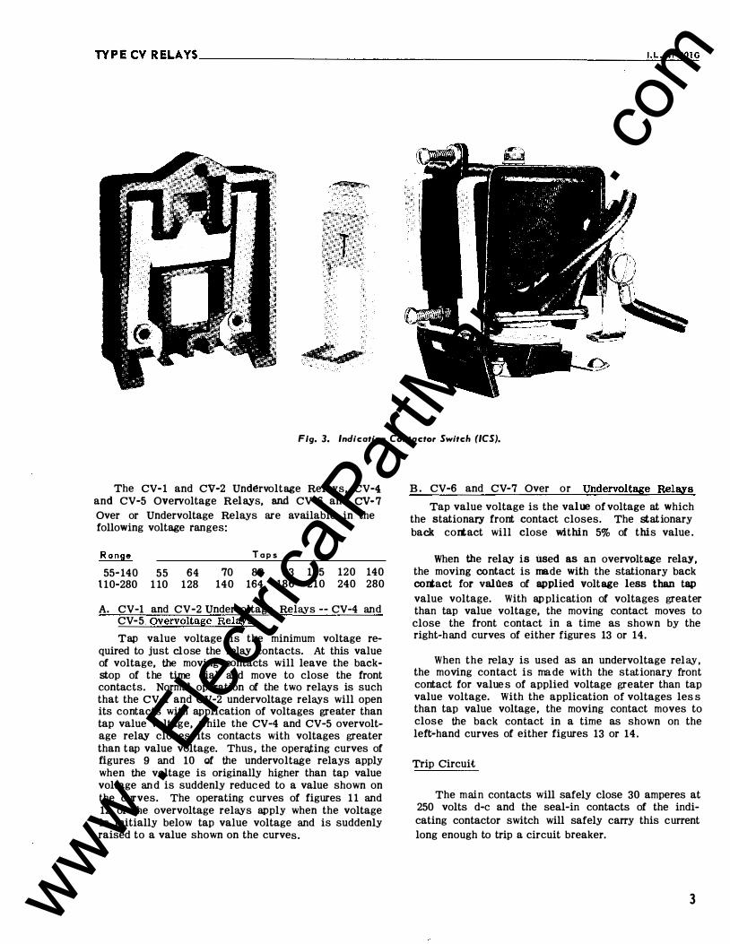
TYPECVRELAYS __________________________________________________________ �I . L�-�4�1 -�20�1 G
··�
-�f. ""''\ , ,, , ,
Fig. 3. Indicating Contactor Switch (ICS).
The CV- 1 and CV-2 Und�rvoltage Relays, CV-4 and CV-5 Overvoltage R elays, and CV-6 and CV- 7
Over or Undervoltage Relays are available in the following voltage ranges:
R a nge
55• 140 55 64 1 10-280 1 10 128
T o p s
70 82 140 164
93 1 05 186 210
120 140 240 280
A. CV-1 and CV-2 Undervoltage Relays -- CV-4 and CV-5. Overvoltage Relays
Tap value voltage is the minimum voltage required to just close the relay contacts. At this value of voltage, the moving contacts will leave the backstop of the time dial and move to close the front contacts. Normal operation of the two relays is such that the CV-1 and CV-2 undervoltage relays will open its contacts with application of voltages greater than tap value voltage, while the CV-4 and CV-5 overvoltage relay closes its contacts with voltages greater than tap value voltage. Thus , the oper;:U;ing curves of figures 9 and 10 of the undervoltage relays apply when the voltage is originally higher than tap value voltage an d is suddenly reduc ed to a value shown on the curves. The operating curves of figures 1 1 and 12 of the overvoltage relays apply when the voltage is initially below tap value voltage and is suddenly raised to a value shown on the curves.
B. CV-6 and CV -7 Over or Undervoltage Relays
Tap value voltage is the value of voltage at which the stationary frort contact closes. The stationary back cortact will close within 5% of this value .
When the relay is 1Jsed as an overvoltage relay, the moving contact is made with the stationary back cortact for vallles of applied voltage less than tap
value voltage. With ap plication of voltages greater than tap value voltage, the moving contact moves to close the front contact in a time as show n by the right-hand curves of either figures 13 or 14.
When the relay is used as an undervoltage relay, the moving contact is ma de with the stationary front cortact for value s of applied voltage greater than tap value voltage. With the application of voltages les s than tap value voltage, the moving contact moves to close the back contact in a time as shown on the le ft-hand curves of either figures 13 or 14.
Trip Circuit
The main contacts will safely close 30 amperes at 250 volts d-e and the seal-in contacts of the indicating contactor switch will safely carry this current long enough to trip a circuit breaker.
3 www . El
ectric
alPar
tMan
uals
. com
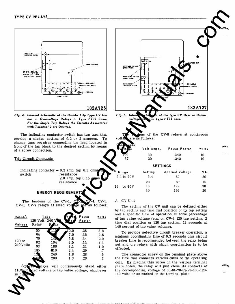
TYPECVRELAYS. ________________________________________________________ �
IIIOitATIIHo t•TACTOI SWITCH
fiiOIIT Ylh
RED IIAIIOLE
TEST SWITCM
TffiMIUl
1 82A72 5
Fig. 4. Internal Schematic of the Double Trip Type CV Un· der or Overvoltage Relays In Type FT l l Cas•. For the Single Trip Relays the Circuits Associated with T ermlnal 2 are Omitted.
The indicating contactor switch has two taps thll.t provide a pickup setting of 0. 2 or 2 amperes. To change taps req uires connecting the lead located in front of the tap block to the desired setting by means of a screw connection.
Trip Circuit Constants
Indicating contactor - 0 . 2 amp. tap 6 .5 ohms d-e switch resistance
2 . 0 amp. tap 0. 15 ohms d-e resistance
E NERGY REQU I REMENTS
The burdens of the CV- 1 , CV-2, CV-4, CV-5, CV-6, CV-7 relays at rated voltage are as follows:
R ated6 T a ps V o lt· P ow e r 120 Volt 240 Volt Amps. F a ctor
V olt a g e Relay Relay
55 1 10 64 128
120 or 70 140 82 164
240 Volts 93 1 86 105 210 1 20 240 140 280
10.0 . 38 7 . 0 . 3 5 5 .8 .34 4 . 0 . 3 3 3 . 1 . 3 1 2.4 . 29 1 . 8 . 28 1 . 3 . 26
Watts
3 . 8 2 . 5 2 .0 1 .3 1 .0
.7
. 5
. 3
6These relays will continuously stand either 110% of rated voltage or tap value voltage , whichever is higher.
4
IIIDICATIAil tOITACTOI SWITtM
FIIOIIT YIIV
Ell SWITCI
1 82A727
Fig. 5. Internal Schematic ol the type CV Over or Undervoltage Relay in Type FT l l case.
The burdens of the CV-8 relays at continuous voltage are as follows:
C o nt i n u o us Volt a g e
199 67
* Rang e
5 . 4 to 2 0 V
1 6 t o 4 0 V
A. CV Unit
V olt Amps.
30 30
P ower F actor
.342
. 342
SETTINGS Sett i n g A p pl i e d Volta g e
5 . 4 67
20 67 16 1 99 4 0 1 99
Watts
10 10
V A
30
1 5 30 20
The setting of the CV unit can be defined either by tap setting and time dial position or by tap setting and a spe c ific time of operation at some percentage of tap value voltage (e.g. on CV-4 120 tap setting, 2 time dial position or 120 tap setting, 12 seconds at 140 percent of tap value voltage).
To provide selective circuit breaker operation, a minimum coordinating time of 0.3 seconds plus circuit breaker time is recommended between the relay being set and the relays with which coordination is to be effected.
The connector screw on the terminal plate above the time dial connects various .turns of the operating coil . By placing this screw in the various terminal plate holes, the relay will just close its contacts at �, the corresponding voltage of 55-64-7Q-82-93- 105- 120-140 volts or as marked on the terminal plat e .
www . El
ectric
alPar
tMan
uals
. com
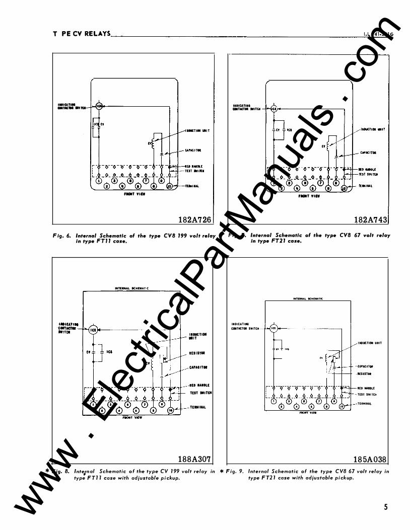
TYPECV RELAYS----------------------------------------------------------��·=L�.4�1�-2�0l�G
IIIICATIII CIITAC'III ., Tal
fDT Willi
1 82A726
F ig. 6. Internal Schematic of the type CVB 1 99 volt relay In type FTJ J case,
tNTIItfiiAL ICHIIIIAT C
IIDUCTIOI lilT
IUI ITOI
CAPAG ITOI
llD IAIOLl TliT IWITCII
TliMIIAL
1 88A307
IIIICATIII CIITACTII WITCA
fDT Willi
1 82A743
Fig. 7. Internal Schematic of the type CVB 67 volt relay In type FT2 J case.
IIDICATIIHI
COITACTOI SWITCM
INTIItNAL SCHt:IIIAnC
I IDUCTIOI UIIT
lED IIAIDLE
- TEST SWI TCI1
TERMUIAL
1 85A038
* Fig. 8. lnte1n al Schematic o f the type CV 1 99 volt relay in * Fig. 9. Internal Schematic of the type CVB 67 volt relay in type F T 1 1 case with adjustable p i ckup. type F T2 1 case with adjustable p i ckup.
5 www . El
ectric
alPar
tMan
uals
. com

TYPE CV R ELAYS __________________________________________________________ __
The nylon scre w on the terminal plate holds the tap plate in pos ition when taps are be ing changed. To
use the position on the terminal plate in which the nylon screw is used, remove the nylon screw and place it in one of the unused holes. Then remove the tap screw and insert it in the terminal plate hole,
Instantaneous Reclosing
The factory adjustment of th e voltage unit cont acts p ro vides a contact foll o w. Where circuit breaker reclosing will be initiated imme di ately after a trip by th e over voltage contact . the time of the opening o f the contacts should b e a minimum . This condition i s obtained by loosening th e stationary contact mounting screw, removing the contact pl ate an d th en replacing th e plate with th e b ent en d resti n g against th e contact spring.
For double trip relays , the upper stationary contact is adjusted such that the contact rests solidly against the back stop . The lower stationary contact is then adjusted s uch that both stationary contacts make contact simultaneously with their respective moving contact .
B. Indicating Contactor Switch ( ICS)
No setting is required on the ICS unit except the selection of the 0 . 2 to 2 . 0 ampere tap setting. Thi s selection is made by connecting the lead located in front of the tap block to the desired setting by means of the conne cting scre w .
INSTAL LAT ION
The relay s should be mounted on switchboard panels or their equivalent in a location free from dirt, moisture, excessi ve vibration , and heat. Mount the relay vertically by means of the four mounting holes on the flange for semi-flush mounting or by means of the rear mounting stud or studs for proj ection mounting. Either a mounting stud or the mounting screws may be utilized for grounding the relay. The electrical connections may be made directly to the terw inals by means of screws for steel panel mounting or to the terminal studs furnished with the relay for thic k p an el mounting. The terminal stud s may be easily removed or inserted by locking two nuts on the stud and then turning the proper nut with a wrench.
For d etailed FT Case information refer to I .L. 4 1-076.
ADJUSTMENTS AND MAINT ENANCE
The proper adjustments to insure correct operation of this relay have been made at the factory. Upon receipt of the relay, no customer adj ustment s, other than those co vered und er "Settings", should be required .
Acceptance Check
The following check is recommended to insure that the relay is in proper working order:
6
A. CV Unit
1 . Contact
a) BY turnin g th e time dial , mo ve the moving contacts
until they d e fl ect th e stationary contact to a posi
tion where the stationary contact is resting against
its backsto p . The index· mark located on the move
ment frame shoul d coincide with the "0" wark on
the time di al . For doub l e trip relays, the foll ow o n
the stationary contacts shoul d be approximately
1/64" .
b) For relays identifi ed with a "T" , lo cated at lower
left of stationary cont act block , the inde x mark on
the movem ent fram e will coincide with the "0" mark on the time dial when the stationary contact
has move d through approximately one hal f o f its
normal defl ection. There fore , with the station ary
contact resting against th e backsto p , th e index
mart< i s off set to the right of the "0" mark by ap
pro xim ately .0 20 " . (For th e typ e CV- 6 and CV-7
relays the back contact has no follo w wh en th e
front contact is through one-half of its follow). The
placem ent of th e various time dial p o sition s in line
with the index mark will give operatin g times as
shown on th e respecti ve time- current curves. For
doubl e trip relays, the follow on the stationary con
tacts should be appro ximately 1/3 2".
2. Minimum Trip Voltage - Set the time dial to position 6. Alternately apply tap val ue voltage pl us 3% and tap value voltage minus 3%.
a. CV-4 and CV-5 Overvoltage Rela,ys, CV-6 and CV-7 Over or Und ervoltage Relays - The moving cont act should leave the backstop at tap val ue ·voltage plus 3% and should return to the backstop at tap value voltage minus 3%.
b. CV- 1 and CV-2 Undervoltage Relay s - The moving cont act should leave the backstop at tap value voltage minus 3% and should return to the backstop at tap value voltage plus 3%.
c. CV-8 Overvoltage Relays - The moving contact should leave the backstop at 8.5% of continuous voltage.
3. Time Curve - Table 1 shows the time curve calibration points for the various types of relays. With the time dial set to the indicated position, apply the voltages specified in table 1 ( e . g. for the CV-4, 140 percent of tap value voltage) and measure the ope rating time of the relay. The operating time should equal those of table 1 plus or minus 5%.
B . Indicating Contactor Switch (ICS) - Close the main relay contacts and pass sufficient d-e current through the trip circuit to close the contacts of the ICS. This value of current should not be gr eat er than the p articular ICS setting being used. The indicator target should drop freely.
www . El
ectric
alPar
tMan
uals
. com
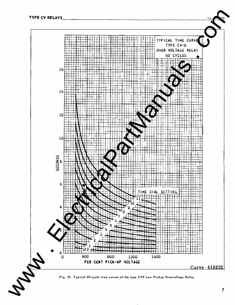
TYPECVRELAYS __________________________________________________________ �,·�L�. 4�1�-2�0�1 G
(/) a
16
14
12
1 0
�8 u Uol (/)
6
2
0 0
TIME
1 1
10
8 9 ·I-r-o ·
7 6
5 �
3 2
1 112
�00 800 1200
P ER CEN T P I CK-UP VOLTAGE
TYPICAL TIME CURVES TYPE CV-8
OVER VOLTAGE RELAY 60 CYCLES
DIAL SETTING
1 600
Curve 41 82 52
Fig. 10. T yp ical 60-cycle time c urves of the type CVB Low P ickup Overvoltage Relay.
7 www . El
ectric
alPar
tMan
uals
. com
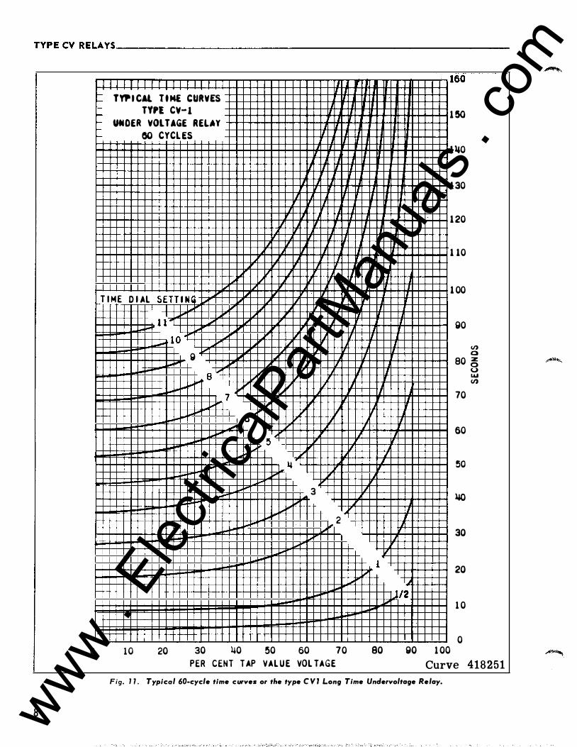
TYPECVRELAYS __________________________________________________________ __
0
8
I I I I I 11 1-1- TYP I CAl T t M£ CURVES - TYPl CY- 1 1/ ,_ � VNOER VOLTAGE RELAY I-
80 CYCL ES IJ 1- J
II II
II II
'J v
IJ v 1/ II
II' IJ 1/ II [.,; T I ME D I AL SETT I N (
.....
.....
1 0
I I I I 1 1 "'1 ,.... 1-- 1 0 .
.... -
20
1..,1 V' � v J [.,; � J 1/ II g !..-II" ,..,. v
a " v "" v 1/ v
7 ""' I'
6 .... ,.. � ,... _ ll L,..o � f-"'
3
1-- 2 ..... ,
..... j,..l""'
""' """"' i""'
30 1+0 50 60 70 PER CENT TAP VAL UE VOL TAGE
r
_l lL
l1 IL
lL II
1 1 I
IJ _j II I II II
II lL
v IJ
II l1 II
_j_
IJ
'( .1_ /
1 , ""'
80
j II
I J
1/
160
1 50
1110
1 30
1 20
1 10
I I 1 00
lJ go
V) 0 80 � 0 LLI V)
II 70
60
�0
lW I
30
20
/2
go 1 00
1 0
0
Curve 418251 Fig. 1 7 . Typical 60-cycle time curves or the type C V J Long Time Unclervoltage Relay.
,......,,
www . El
ectric
alPar
tMan
uals
. com
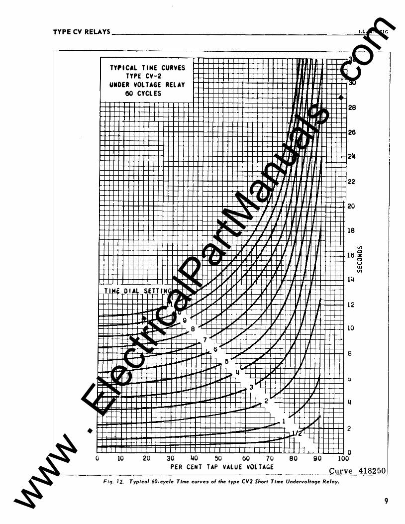
TYPECV RELAYS --------------------------------------------------------���-L�-�41�-2�0�1G
0
32
TYP I CAL T I ME CURVES
TYPE CV-2
UNDER VOLTAGE REL AY 30 60 CYCL ES
28
' J 26
I
I 22
I 20
I '
18 I� II I I r r , I J " 7 !/ I 1
II � J IT 1 ""' 7 T l -41 D I AL SETTIN G
'f' � 1.) I � I� I� , I I I .. 1 1 ,.,.
1 � I I 2 ... 10 """ ,_, g ""
1,.. 8 � 1 ""' � .J J II 0
7 ..... Iii" 6 !iii' """ ""' 8 :.- 5 ...... J
14 1/ , 0
3 , I j;ii L... � ... 2
.... " 1 � �rt 2
I I I I I I 0 10 20 30 140 50 60 70 80 90 100
P E R CEN T T AP VAL U E VOL TAGE Curve 41 82 50
Fig. 7 2. Typical 60-cycle Time curves ol the type CV2 Short Time Undervoltage Relay.
9 www . El
ectric
alPar
tMan
uals
. com

TYPECVRELAYS ________________________________________________________ __
1 0
1 60
1 !50
1 110
130
1 20
1 1 0
1 0 0
V) a z 80 8 .... V)
70
60
!50
110
30
20
1 0
0 0
I
9 8
7
6
!5 11
3
2
1 "!.. !/2.
1 10 1 20 1 30 1 110
TYP I CAL T I M E C U R V ES
TYPE C V-�
OVER VOLTAGE RELAY
60 CYCL ES
1 1 T I ME D I AL SETT I N G
10
1 !50 1 60 1 70 180 1 90 200 2 1 0 220 230 2110 2!50 P E R C E N T OF TAP V A L U E VOL TAGE
406C881
Fig. 13. Typical 60-c ycle time curves of the type CV4 Long Time Overvoltage Relay.
www . El
ectric
alPar
tMan
uals
. com
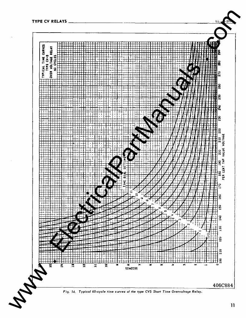
TYPECV RELAYS--------------------------------------------------------��·�L�·�41�-2�0�1G
Ill ... ,.... > <!I • � � ... (,J •
., Ill ... . ... ... ::E > UI � - u•u ... ... ,....
... � (,J -' IL O
� � > � -
.. ,.. ...
• ... > 0
lA .. Sit - ... .,.. -
:z -... ... ... <J'I ... • -a ... % ...
..... .... 2
01
c;(l ,.. SON003S
(X) ....
<0
10
;t
M
N
.....
Fig. 14. Typical 60-cycle time c urves of the type CVS Short Time Overvoltage Relay.
N :::;
! 0
fJ 0 ....
'W
� N
� N
� � N
0 N N
0 -N
0 0 N
0 � 0 s
0 ....
0 10
0 -
8 -
0
406C884
1 1 www . El
ectric
alPar
tMan
uals
. com
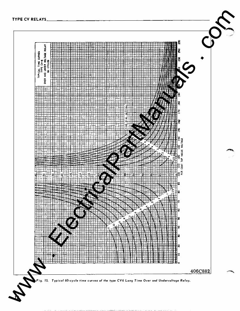
TYPECVRELAYS ________________________________________________________ __
1 2
"' ... > 0
0 "' 0 0 0 a 0 <D
SONOJ3S
0 ....
,_ ,_ "' ... oC
Q ... :1:
0 "'
<D
� "'
N
2 N
0 � 0 ... N
0 N N
� N
s .. 0 � 0 � 0 � � � :i ... - "'
oC ,_ ...
0 0 <'> > ...
N :: oC
0 > � N - a.. oC ,_ 0 1-- z - ...
u a: � 0 � �
0 "' � 0 "'
0
F i g. 1 5. Typ ical 60- cycle time c urves of the type CV6 Long T i me Over and Undervoltage Relay.
406C882
�
www . El
ectric
alPar
tMan
uals
. com
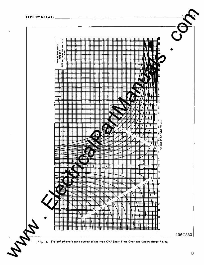
TY PE CV RELAYS __________________________________________________________ �I. L�-�4�1 -�20�1�G
-� ,. 0
:::
::: 2
I
"'
SONO:l3S
s
8 ..,
0 � 0 ill 0 t;; 0 "' "'
� g "'
� 0 g: 0 N
0 � 0 s 0 � 0 ,_
0 ::! 0 �
0 =: g 0 "'
0
0 0
0 "'
0 "'
g g 0 .,
0 "'
0 ..,
� 2
Fig. 1 6. Typical 60·cycle time curves of the type CV7 Short Time Over and Unclervoltage Relay.
406C883
1 3 www . El
ectric
alPar
tMan
uals
. com
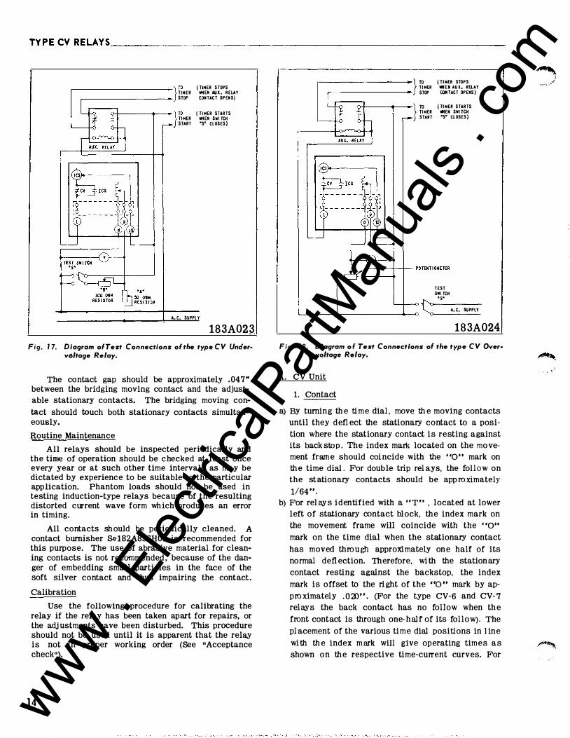
TYPECVRELAYS ________________________________________________________ ___
r (TIMER STOPS TINER WHEN AUX. RELAY STOP CONTACT OPEIIS)
r (TI MER STARTS TI MER WHEN SOl TCH START 'S' CL OSES)
A. C. SUPPL Y
183A02 3 Fig. 1 7. Diagram ofTest Connections of the type CV Unc!er·
v6ltage Relay.
The contact gap should be approximately . 047" between the bridging moving contact and the adjustable stationary contacts. The bridging moving con
tact should touch both stationary contacts simultaneously.
Routine Maintenance
All relays should be inspected periodically and the time of operation should be checked at least once every year or at such other time intervals as may be dictated by experience to be suitable to the particular application. Phantom loads should not be used in testing induction-type relays because of the resulting distorted current wave form wh ich produces an error in timing.
All contacts sh ould be periodically cleaned. A contact burnisher S1tl82A836H01 is recommended for this purpose. The use of abrasive material for cleaning contacts is not recommended , because of the danger of embedding small particles in the face of the soft silver contact and thus impairing the contact .
Calibration
Use the following procedure for calibrating the relay if the relay has been taken apart for repairs, or the adj ustments have been disturbed. This procedure should not be used until it is apparent that the relay is not in proper working order (See "Acceptance check").
1 4
ro TI NER STOP
ro TI MER START
( Tl MER STOPS WHEII AUX. RUAY CONTACT OPEIIS)
(TINER STARTS WHEII SOl TCH 'S' Cl OSES)
TEST SOl TCH
L-....___.....__,t: •s•
A. C. SUPPLY
183A024
Fig. 18. Diagram of Test Connections ol the type CV Over• voltage Relay.
A. CV Unit
1. Contact
a) BY turning th e time dial , move th e moving contacts until they defl ect the stationary contact to a posi
tion where the stationary contact is resting against its back stop . The index mark located on the mo vement fram e should coi ncide with the "0" mark on th e time dia L For double trip rel ays, the follow on the st ationary contacts should be app ro ximately
1/64 " . b) For rei ay s identified with a " T " , located at lower
left of stationary contact block, the index mark on the movement frame will coincide with the "o•• mark on the time dial when the stationary contact
has moved thro u gh approximately on e half of its
normal defl ection. Therefore, wi th the station ary
contact resting against the backstop, the index
mark is offset to the ri ght of the "0 " mark by ap
pro ximately . O al" . (For the type CV-6 and CV- 7 relays the back contact has no follow when th e
front contact is through one-half of its follow). The
pl acement of the various tim e dial positions in l ine
wi th th e index m ark will give operating times as shown on th e respective time-current curves. For
� ",j/
www . El
ectric
alPar
tMan
uals
. com
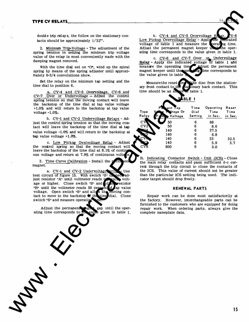
TYPE CV RELAYS __________________________________________________________ I_. L_. _41_·2�0�1 G
doubl e trip rel ay s, the follow on the stationary contacts should be approximately 1/32".
2. Minimum Trip-Voltage - The adj ustment of the spring tension in setting the minimum trip voltage value of the relay is most conveniently made with the damping magnet removed.
With the time dial set on "0", wind up the spiral spring by means of the spring adjuster until approximately 6-3/4 convolutions show.
Set the relay on the minimum tap setting and the time dial to position 6.
a. CV-4 and CV-5 Overvoltage, CV-6 and CV-7 Over or Undervoltage - Adjust the control spring tension so that the moving contact will leave the backstop of the time dial at tap value voltage + 1 .0% and will return to the backstop at tap value voltage -1.0%.
b. CV-1 and CV-2 Undervoltage Relays - Adjust the control spring tension so that the moving contact will leave the backstop of the time dial at tap
value voltage -1.0% and will return to the backstop at tap value voltage +1.0%.
c. Low Pickup Overvoltage Relay - Adjust the cortrol spring so that the moving contact will leave the backstop of the time dial at 8. 1% of continuous voltage and return at 7.9% of continuous voltage.
3 . Time Curve Calibration - Install the permanent magnet.
a. CV-1 and CV-2 Undervoltage Rela,y - use test circuit of figure 15. With switch "S" opened , adjust resistor "A" until voltmeter reads tap value voltage or higher. Close switch "S" and adjust resistor "B" until the voltmeter reads 50 percent of tap value voltage. Ope n switch "S" and allow the moving contact to move to the backstop of the time dial. Close switch "8" and measure operating time.
Adjust the permanent magnet gap until the operating time corresponds to the value given in table 1 .
b . CV-4 and CV-5 Overvoltage Rel ay, CV-8 Low Pickup Overvoltage Relay - Apply the indicated voltage of table 1 and measure the operating time. Adjust the permanent magnet keeper until the operating time corresponds to the value given in table 1 .
'
c. CV-6 and CV-7 Over or Undervoltage � - Apply the indicated voltage of table 1 artd meastre the operating time. Adjust the permanent magnet keeper until the operating time corresponds to the value given in table 1.
Measure the reset time of the disc from the stationary front contact to the stationary back contact. This time should be as shown in table 1 .
TABLE I
P er c e nt T a p T i me Operat i n g R e set Type V a l ue V o l t a g e Or D i o l T i me T i me R e l a y P i c k u p Vo l t a g e Sett i n g i n Se c . i n Sec .
CV1 50 6 68 CV2 50 6 8. 6 CV4 140 6 37.5 CV5 140 6 6. 8 CV6 140 6 33 32.5 CV7 140 6 5 . 9 5 . 7 cvs 800 6 3.0
B. Indicating Contactor Switch - Unit (ICS) - Close the main relay contacts and pass sufficient d-e current throug h the trip circuit to close the contacts of the ICS. This value of current should not be greater than the particu lar ICS setting being used. The indicator target should drop freely.
RENEWAL PARTS
Repair work can be done most satisfactorily at the factory. However, interchangeable parts can be furnished to the customers who are equipped for doing repair work. When ordering parts, always give the complete nameplate data.
1 5 www . El
ectric
alPar
tMan
uals
. com
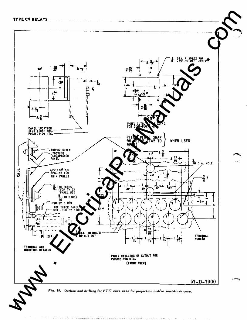
1 6
!-l�o�c��fcK PANEL USE !._- 18 SlUD) 18
• 190-32 SCREW FOR TH I CK PAII EL USE • 1 90-32 STUD .._.,.,�---
TEIIMIIAL AIID MOUITI.G DETAILS
f
� I L OT Pl ATE SHAP} R�A�LAY ( TA� TO WHEH USED
�� DRILLIMG OR CUTOUT FOR .-.. �CTIOI MTG.
(FDT YIEW)
s ! 8
Fig. 1 9· Outline and drilling f FTJ l 57 -D-7900
or case d I use or projection and/or se . f/ h ml• us case.
www . El
ectric
alPar
tMan
uals
. com
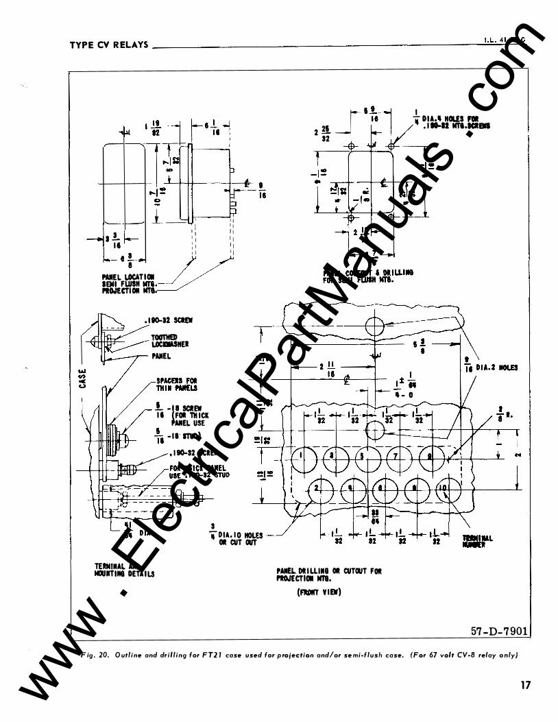
TYPE CV RELAYS --------------------------------------------------------�� -�L�- �41�·2�0l�G
.... �
a .!. r---I t
- e .L.,.. i
l _ _ , : :
I I II I I 1 1 1 1 1 1 1 1 I I I I I'AIIEL �TIOII __/ / SEMI FWS11 m.� .. O.ItCTI OII Nf'8,
. 1 80-32 SCI£W TOOT1t£D LOCIIASKEJ
�..-r-- I'AIIEL
.!_ ·18 SCIEW I I FOit THICK
TERMIIIAL AIID MOUIITIIIG DETA I LS
AIIEL USE �� - II ITID) , 1 80-32 SCREW
3 "i"DIA. I O NOW Olt CUT OUT
_[I �� ___, .!. DIA,, KOUS Fell
2 21 _ 1 ./' . r eo-at m.�e�aa 32 ¥-
I'AIIEL DI I UIIIG Olt CUTOUT FOR I'IOJtCTIOII Mra.
(FIDIO' VIEW)
57-D-7901
F ig . 20. O utline and drilling for F Tl l case used for p rojection and/or se mi-flush case. (For 67 volt CV-8 relay o nly)
1 7 www . El
ectric
alPar
tMan
uals
. com

www . El
ectric
alPar
tMan
uals
. com

www . El
ectric
alPar
tMan
uals
. com
W ESTINGHOUSE ELE C T R I C C O R P O R A T I O N RELAY- I NSTRU MENT D IVI S I O N NEWARK, N. J.
Printed in U.S.A. www . El
ectric
alPar
tMan
uals
. com
Westinghouse I .L.41-20 1 F
INSTALLATION • OPERATION • MAINTENANCE
INSTRUCTION S
TYPE CV VOLTAGE RELAY
C AU T I ON Before putting relays into servi ce , remove all blocking which may have been inserted for the pur· pose of securing the parts during shipment , make sure that all moving parts operate freely, insp ect the co n· tacts to see that they are cl ean and close properly, and operate the relay to check the settings and electrical connections.
APP LICATI ON
The type CV rel ays are single-phase inductiondi sc type relays operating either on under or over voltage or both. These relays are applied as a voltage fault detector operating in conjunction with other protective relays. The relays are also used as timing devices for various automatic operations.
CONTENTS
This instruction leaflet applies to the following types of relays:
CV-1 Long Time Undervoltage Relay CV-2 Short Time Undervoltage Relay CV-4 Long TilT'e Overvoltage Relay CV-5 Short Time Overvoltage Relay CV-6 Long Time Over or Undervoltage Relay CV-7 Short Time Over or Under voltage Relay CV-8 Low Voltage Pickup Overvoltage Relay
CONSTRUCTION AND OPERATION
The types CV- 1 , CV-2, CV-4, CV-5, CV-6, and CV-7 relays consist of a voltage unit and an indicating contactor switch (ICS). The principal component parts of the relay and their loc ation are shown in figures 1, 2, and 3.
The type CV-8 relay in addition to the above components also has a capacitor which is series tuned with the main coil of the electromagnet. This tuned circuit offers a low impedance to fundamental current and a high impedance to third harmonic currents. Hence, the relay has a low pick up value for fundamental voltage and a much higher value of pickup for third harmonic voltage. At rated voltage the electromagnet is saturated causing the circuit to be detuned. The impedance of the circuit is increased and limits the fundamental current to a safe value.
SU P E RSEDES I . L. 41-20 1 E * Denotes ch ange from superseded i ssue.
A. Voltage Unit (CV)
The overvoltage unit operates on the inductiondisc principle. A main tapped co il located on the center leg of an "E" type laminated structure produces a flux which divides and returns through the outer legs. A shading coil causes the nux through the left leg (front view) to lag the main pole flux. The out-ofphase fluxes thus produced in the air gap causes a contact closing torque.
The undervoltage unit operates on the same principle as the overvoltage unit except the shading coil is on the right leg (front view). This causes the out-of-phase fluxes to produce a contact opening torque.
B. Indicating Contactor Switch (ICS)
The indicating contactor switch is a small d-e operated clapper type device . A magnetic armature, to which leaf-spring mounted contacts are attached , is attracted to the magnetic core upon energization of the swi tch. When the switch closes, the moving contacts bridge t wo stationary contacts, completing the trip circuit. Also, during this operation two fingers on the armature deflect a spring located on the front of the switch, which allows the operation indicator target to drop. The target is reset from the outside of the case by a push rod located at the bottom of the case.
The front spring, in addition to holding the target, provides restraint for the armature and thus controls the pickup value of the switch.
CHARACTERISTICS
The low pickup CV-8 Overvoltage Relay is available with the following continuous voltages .
6 7 volts 199 volts
The m1rumum voltage required to just close the CV-8 contacts is 8% of the continuous voltage. TYPi· cal operating time s of the type CV-8 relay are shown on figure 8.
The CV-1 and CV-2 Undervoltage Relays, CV-4 and CV-5 Overvoltage Relays, and CV-6 and CV- 7
EFFECTI V E NOV EMBER 1 965 www . El
ectric
alPar
tMan
uals
. com
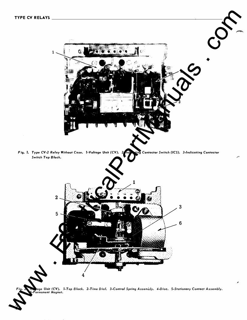
TYPE CV R E LAYS
1
2
F ig. 1. Type CV-2 Relay Without Case. 1-Voltage Unit (CV}. 2-lndicating Contactor Switch (ICS}. 3-lndicating Contactor
Switch Tap B lock.
2
3
5
6
4
Fig. 2. Voltage Unit (CV}. 1- Tap B lock. 2- Time D ia l. 3- Control Spring A ssembly. 4-D isc, 5-Stationary Contact A ssembly. 6-Permanent Magnet.
2 www . El
ectric
alPar
tMan
uals
. com
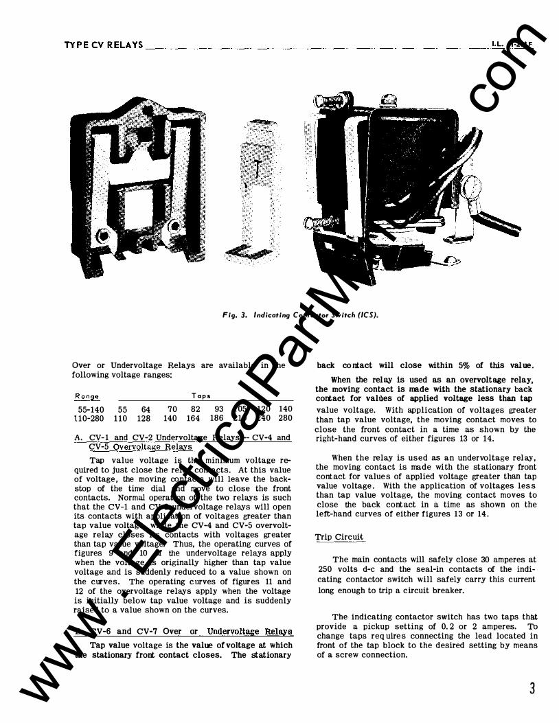
TYPECVRELAYS __________________________________________________________ �I�. L�· �41�-2�0�1 F
Fig. 3. Indicating Contactor Switch (ICS).
Over or Undervoltage Relays are available in the following voltage ranges:
R a nge
55-140 55 64 1 10-280 1 10 128
T a p s
70 82 140 164
93 1 05 120 140 186 210 240 280
A . CV- 1 and CV-2 Undervoltage Relays -- CV-4 and CV-5 Overvoltage Relays
Tap value voltage is the minimum voltage required to just close the relay contacts. At this value of voltage , the moving contacts will leave the backstop of the time dial and move to close the front contacts. Normal operation of the two relays is such that the CV-1 and CV-2 undervoltage relays will open its contacts with application of voltages greater than tap value voltage , while the CV-4 and CV-5 overvoltage relay closes its contacts with voltages greater than tap value voltage. Thus, the operating curves of figures 9 and 10 of the undervoltage relays apply when the voltage is originally higher than tap value voltage and is suddenly reduced to a value shown on the curves. The operating c urves of figures 11 and 12 of the overvoltage relays apply when the voltage is initially below tap value voltage and is suddenly raised to a value shown on the curves.
B. CV-6 and CV-7 Over or Undervoltage Relays
Tap value voltage is the value of voltage at which the stationary front contact closes. The stationary
back co ntact will close within 5% of this value .
When the relay is used as an overvoltage relay, the moving contact is made with the stationary back cortact for values of applied voltage less than tap
value voltage. With application of voltages greater than tap value voltage, the moving contact moves to close the front contact in a time as shown by the right-hand curves of either figures 13 or 14.
When the relay is used as an undervoltage relay, the moving contact is made with the st ationary front cont act for value s of applied voltage greater than tap value voltage . With the application of voltages les s than tap value voltage, the moving contact moves to close the back cont act in a time as shown on the left-hand curves of either figures 13 or 14 .
Trip Circuit
The main contacts will safely close 30 amperes at 250 volts d-e and the seal-in contacts of the indicating contactor switch will safely carry this current long enough to trip a circuit breaker.
The indicating contactor switch has two taps that provide a pickup setting of 0. 2 or 2 amperes. To change taps req uire s connecting the lead located in front of the tap block to the desired setting by means of a screw connection.
3 www . El
ectric
alPar
tMan
uals
. com
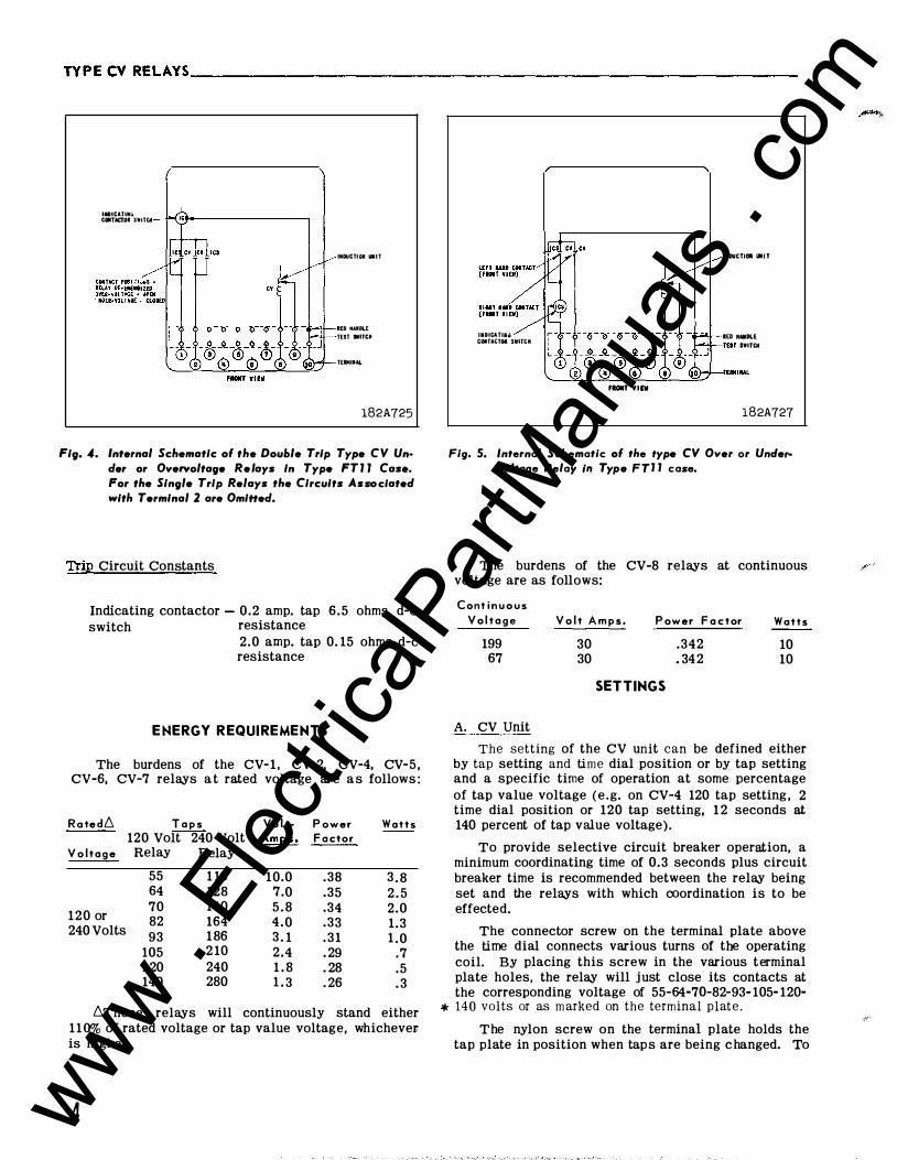
TYPECVRELAYS __________________________________________________________ __
IIDICATUIIO CCMTACI'OI SWITCM
IIIDUCTI OII UIIT
RED MAIIDLE
TEST IIITCII
TEJMIIIAL
182A725 Fig. 4. Internal Schematic of the Double Trip Type CV Un·
Jer or Overvoltage Relays In Type FT J J Case. For the Single Trip Relays the Circuits As-elated with Terminal 2 are OmiHeJ.
Trip Circuit Constants
Indicating contactor - 0.2 amp. tap 6.5 ohms d-e switch resistance
2.0 amp. tap 0. 15 ohms d-e resistance
ENERGY REQUIREMENTS
The burdens of the CV- 1 , CV-2, CV-4, CV-5 , CV-6, CV-7 relays a t rated voltage are a s follows :
R o te d6
V o lt a g e
120 or 240 Volts
T a p s 120 Volt 240 Volt
Relay Relay
55 1 10 64 128 70 140 82 164 93 1 86
105 2 10 1 20 240 140 280
Vo l tAmp s .
10.0 7.0 5 . 8 4 . 0 3 . 1 2 . 4 1 . 8 1 . 3
P ower F a ctor
.38
.35
.34
.33
. 3 1
. 29
. 28
. 26
W a t t s
3 . 8 2 . 5 2.0 1.3 1 .0
.7
.5
. 3
6These relays will continuously stand either 1 1 0% of rated voltage or tap value voltage, whichever. is higher.
4
UIDICATIAU COtiTACTOI SWITttl
FROIIT YIEV
IIIDUCTIOI llll l
lED MAIIDI.E TEST SWITCM
182A727
Fig. 5. Internal Schematic of the type CV Over or Undervoltage Relay il! Type FTJ J case.
The burdens of the CV-8 relays at continuous voltage are as follows:
Cont i n u o u s V o l t a g e
199 67
A. CV Unit
V o l t A m p s .
30 30
P ower F a c tor
.342
. 34 2
SETTINGS
W a t t s
10 10
The setting of the CV unit can be defined either by tap setting and time dial position or by tap setting and a specific time of operation at some percentage of tap value voltage (e .g. on CV-4 120 tap setting , 2 time dial position or 120 tap setting, 1 2 seconds at 140 percent of tap value voltage).
To provide selective circuit breaker operation, a minimum coordinating time of 0.3 seconds plus circuit breaker time is recommended between the relay being set and the relays with which coordination is to be effected.
The connector screw on the terminal plate above the time dial connects various turns of the operating coil. By placing this screw in the various terminal plate holes, the relay will just close its contacts at the corresponding voltage of 55-64-7G-82-93- 105- 120-* 140 volts or as m arked on the terminal plat e .
The nylon screw on the terminal plate holds the tap plate in position when tap s are being c hanged. To
www . El
ectric
alPar
tMan
uals
. com
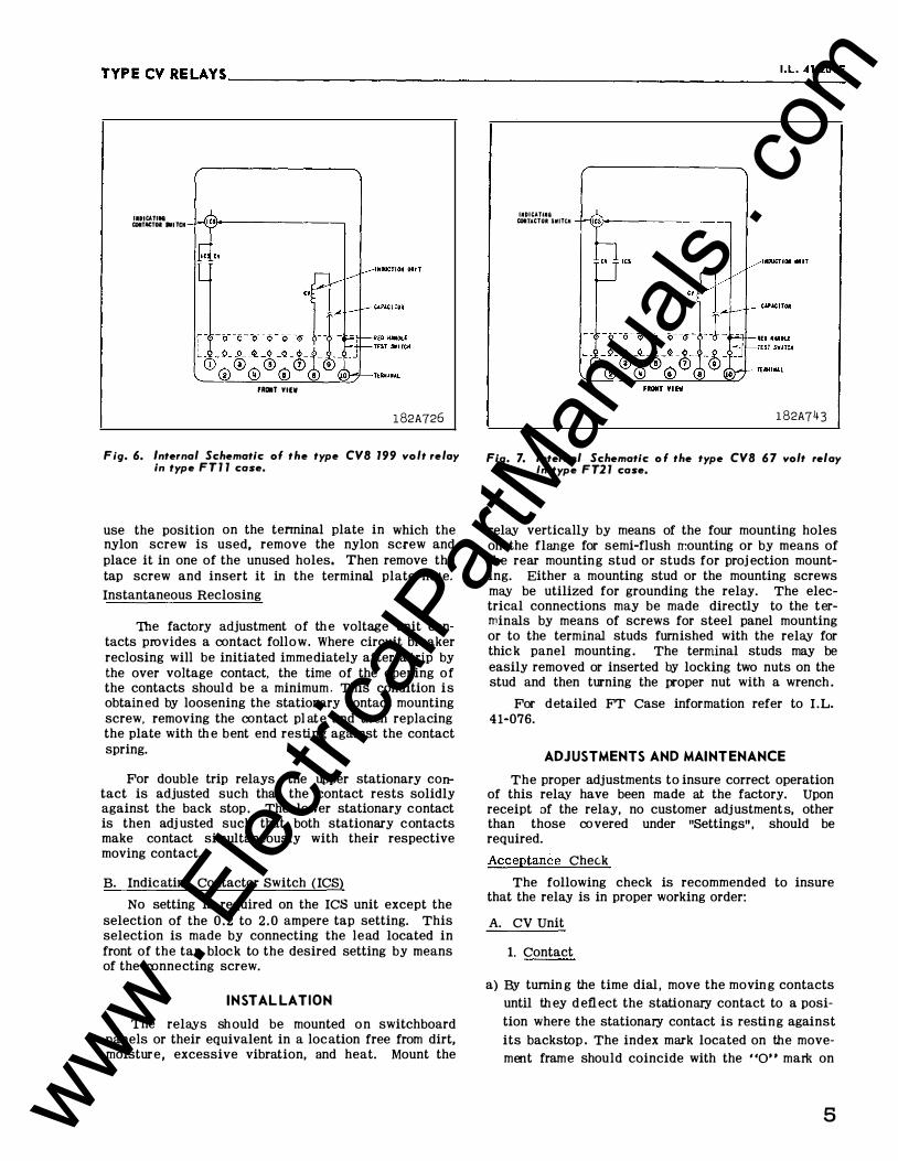
TYPECVRELAYS ___________________________________________________________ 1 · L_•_4_1 -_
2o_l_F
IIDICATIII8 COIT&CTDI IWI TCH
fROIIT YllW
182A726
Fig. 6. Internal Schematic of the type CVB 199 volt relay in type F T 1 1 case.
use the position on the tenninal plate in which the nylon screw is used, remove the nylon screw and place it in one of the unused holes. Then remove the tap screw and insert it in the terminal plate hole.
Instantaneous Reclosing
The factory adjustment of th e voltage unit contacts provides a contact follow. Where circuit breaker reclosing will be initiated immediately after a trip by the over voltage contact, the time of the opening of the contacts shoul d be a minimum . This condition is obtain ed by loosening the stationary contact mounting screw, removing the contact pl ate and th en replacing the plate with th e bent end resting against the contact spring.
For double trip relays , the upper stationary contact is adjusted such that the contact rests solidly against the back stop . The lower stationary contact is then adj usted such that both stationary contacts make contact simultaneously with their respective moving contact.
B. Indicating Contactor Switch (ICS)
No setting is required on the ICS unit except the selection of the 0 . 2 to 2 . 0 ampere tap setting. This selection is made by connecting the lead located in front of the tap block to the desired setting by means of the ronnecting screw.
INSTAL LATION
The relays sh ould be mounted on switchboard panels or their equivalent in a location free from dirt, moisture, excessive vibration, and heat. Mount the
UID"ATIIUi COITACTOR SWITCH
182A743
Fig. 7. Internal Schematic o f the type CVB 6 7 volt relay In type F T2 1 case.
relay vertically by means of the four mounting holes on the flange for semi-flush rr.ounting or by means of the rear mounting stud or studs for proj ection mounting. Either a mounting stud or the mounting screws may be utilized for grounding the relay. The electrical connections may be made directly to the terminals by means of screws for steel panel mounting or to the terminal studs furnished with the relay for thic k panel mounting . The terminal studs may be easily removed or inserted by locking two nuts on the stud and then turning the proper nut with a wrench .
For detailed FT Case information refer to I .L. 41-076.
ADJUSTMENTS AND MAINTENANCE
The proper adjustments to insure correct operation of this relay have been made at the factory. Upon receipt of the relay, no customer adjustment s, other than those covered under "Settings" , should be required.
Acceptance CheC;k
The following check is recommended to insure that the relay is in proper working order:
A. CV Unit
1. Contact
a) By turnin g the time dial , move the movin g contacts
until th ey d efl ect the stationary contact to a posi
tion where the stationary contact is resting against
its backstop . The index mark located on the movement frame should coincide with the "0" mark on
5 www . El
ectric
alPar
tMan
uals
. com
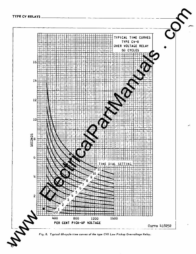
TYPECVRELAYS __________________________________________________________ ___
6
<./) 0
16
12
1 0
� 8 u UJ <./)
6
2
0 0
TIME
1 1
10
9 8
7 6
5 �
3
2
1 112
�00 800 1200
P ER CEN T P I CK-UP VOL T AGE
TY P I CAL T I ME CURVES TYP E CV-8
OVER VOLTAGE RELAY 60 CYCL ES
DIAL SETTING
1 600
Curve 418252 Fig. 8. Typical 60-cyde time curves of the type CVB Low P ickup Overvoltage Relay.
www . El
ectric
alPar
tMan
uals
. com

TY PE CV RELAYS ___________________________________________________________ I ._L._4_1 -_2o_l_F
0
I I I I I I I I I I I I I 1- TYP I CAl HM£ CURVES 1-- TYPl CV-1 1-� VNDER VOLTAGE RELAY I f--� 60 CYCL ES
II IT 1
I I II IT
I
IJ If 1/ II
II li 1.1 II v v T I ME D I AL SETT I N ' WI' :,... �
1 0
I I 1 I
� l l "'': ...
.... 1 0
--
...
....
20
� � 1.1 ;t .I
/ J 1.1 ... 9 LJ I"'" I� If
81,' t...o'
;;;; � 1.1 1/
7 � ... � 6 ... � , , !5 ... � � 4 """ ..... 17' ..... 3
!.-'
.... 2 ..... v ""' I--' ""' r-
� ........
........
....
30 40 50 60 70
PER CEN T TAP VAL U E VOL TAGE
7
II
I
II J II I J w I II IT If
II
1 II
1 I II
I
J
I./
v 1
�
�;;iii � I-"
80
11
l
!/
I I
If
7
11
IJ I I
� 1/2
QO
160
1 �
1 40
1 30
1 20
1 10
100
90
II) a 80 �
70
60
50
30
20
10
0 1 00
0 w (I)
Curve 418251 Fig. 9. Typical 60-cycle time curves or the type C V J Long Time Unclervoltage Relay.
7 www . El
ectric
alPar
tMan
uals
. com
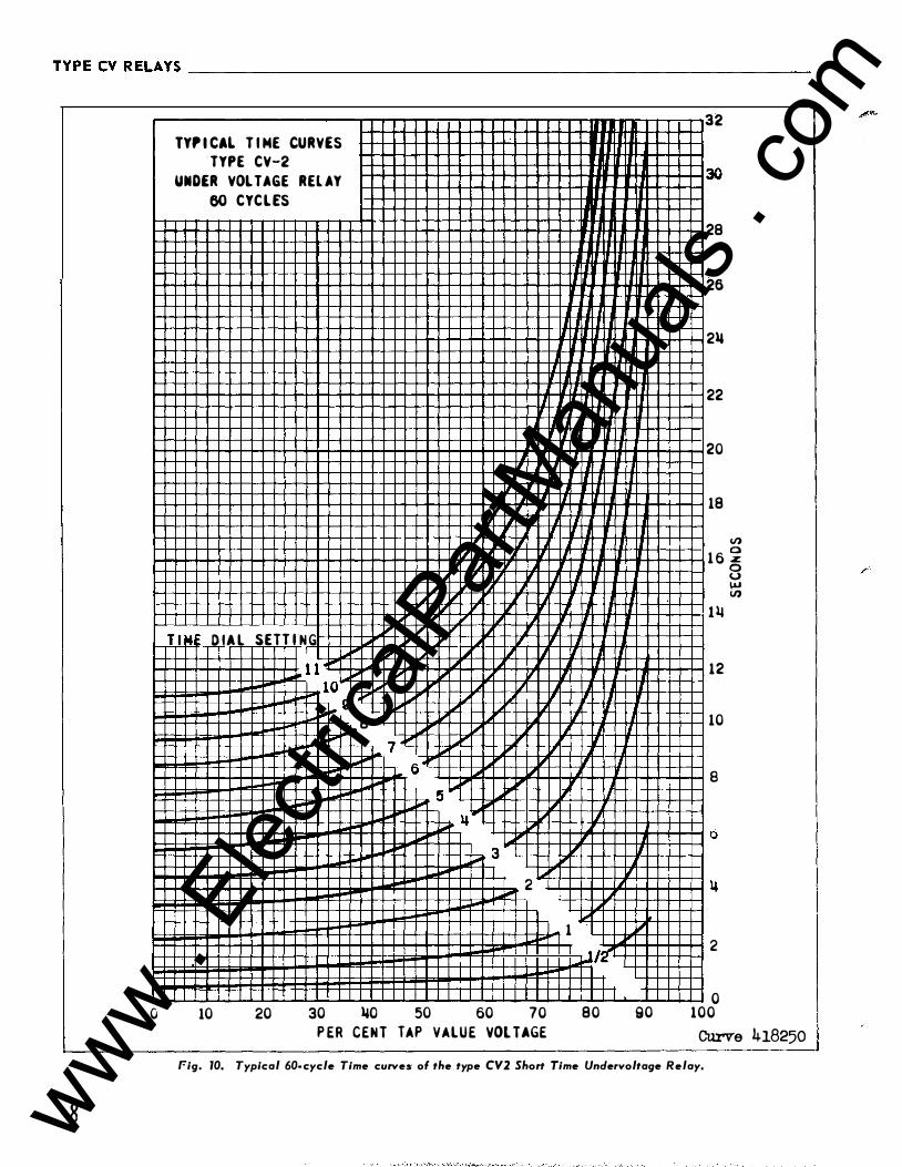
TYPECVRELAYS ________________________________________________________ ___
0
8
lYr i CAL T I ME CURVES
TYPE CV-2
UNDER VOLTAGE REL AY
60 CYC L ES
I
I
'( I� I� II , If L II'
I;" T l � D IA L SETT IN G
""' ""' � II'" I L.; i.o" � .I J
.... � 1 1 � I' , � � � I""' 10 L.; io- 9 "
.. 8 .. � I""' 7 I' � I""' If I""' 6 L..o' II" I' � """'"" 5 ...
ll II'"
... , 3
I"' - 2 I"" ...
"""
10 20 30 llO 50 60 70
P ER CENT TAP VALUE VOL TAGE
II
l
II
I lL
L j l1 II 'I ' 'l
l l
If I I
I 'I
II J I 'I
, I
, ""'
1
.,_ J-r I
80
I I
' I
II
I I
1-'
90
32
30
28
26
2ll
22
20
18
V) 1 6 �
1�
12
10
8
2
0 100
0 u � II)
Curve 418250 r-ig. 10. Typical 60- cycle Time curves of the type CV2 Short Time Undervoltage Relay.
,_,,
www . El
ectric
alPar
tMan
uals
. com
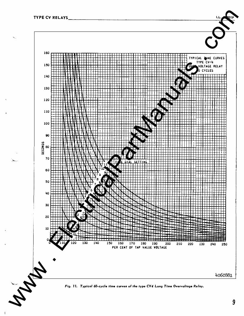
'"""'" ''
TYPECVRELAYS __________________________________________________________ I._L._4_1_-�_t __ F
1 60
1 !50
1 �0
130
1 20
1 10
100
90 "' 0 z 80 8 .... "'
70
60
!50
�0
30
20
10
0 0 1 10
9 8
7
6
!5
�
3
2
1
l/?,
1 20 130 1 �0
TYP I CAL T I ME C U R V E S
TYPE C V•li
OVER VOLTAGE R E L A Y
60 C Y C L ES
1 1 T I ME D I AL SETT I NG
10
� 1 50 1 60 1 7 0 1 80 1 90 200 2 1 0 220 230 2�0 2!50
P E R C E N T OF TAP V A L U E VOLTAGE
4o6c88I Fig. J J. Typical 60-cycle time curves ol the type CV4 Long Time Overv.oltage Re lay.
9 www . El
ectric
alPar
tMan
uals
. com
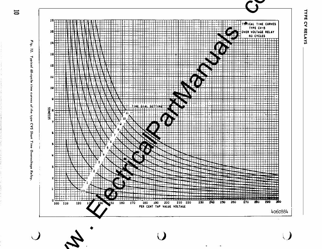
""""'" c:;:)
., �-� -1 � n· 2.. ? n '< n ii" ... 3" ID n !; < ID .. 0 ..... ... ,... ID � ID I") -<: VI "' ,... 0 ::t -1 3" ID 0 < ID .. < 0 :;Q IQ ID ::0 ID Q �
�J
�'' r t i
I
I
!
1'.
t' tO' ' 9
<n Q � 8 ... <n ' 1
i i 5 i
ll I
3 I
�
J,
0
6 !5
14 3
2
1 112.,..
t nn t t n t<>n t <�n l lU\ 1 11 0
T I ME D I AL SETT I H
l l 10
II 8
7
l AO 1 70 IRO IQO 200 2 10 220 230
PER CEHT TAP VALUE VOLTAGE
l)
2'10 2!50 260
TYP I CAL T I ME CURVES
TYPE CV•5
OVER VOL TAG£ RELAY
60 CYCLES
70 280 2iO 3CO 4o6c884
\ )
-1 -< "tl m n < ;;o m r ,.. -< Cit
www . El
ectric
alPar
tMan
uals
. com
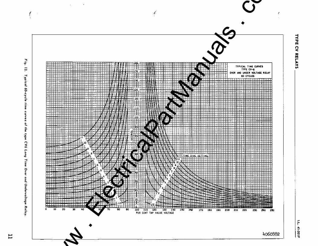
...... ......
"TT �· -!-"' -1 "< 'tl ;:;· � 0\ '? n "< n ii" .. 3' ID n c: .. < ID .. 0 .... ;. ID � 'tl ID I") "< 0\ r-0 :J ICI -1 3' ID 0 < ID .. 0 :J 0... c:: :J 0... ID .. < 0 .. Q ICI ID ;;o ID Q �
I
I
I
1 1
10
Q 8
7
6 5
lj ' 3
I I I I I I I I I I I I I I I I I I I I I I I � lo<l'1l I I I I 11 • 2
1 1 1 1 1 1 1 1 1 1 1 1 1 1 1 1 1 1 1 1 1 1 1 1 1 1 1 1 1 1 1 1 1 1 1 1 1 ffl :'121 0 10 20 ao 110 50 50 70 80 90
m 1 50 If 1110 ±f 130
m 120
m 1 1 0
m 100
I "' 0 8Hao .... "' _,_j_j_j
70
50
lj ill 0
10
l 0
l
2 /2
lj 3
6 5 7
1 1 10 Q 8
T I ME D I AL SETT I N
TY P I CAL T I M( CURY£5 TYP£ CY•O
OVER AND UNDER VOLTA&£ R flAY
00 CYCLES
f
100 1 1 0 120 130 1 ll0 1 !10 1041 1?0 180 190 200 210 220 230 2110 2SO PER CENT TAP VALUE VOLTAGE
4o6c882
� ., m n < ::a m r ?( Cit
:-r � 0 ... 0 -"'I
www . El
ectric
alPar
tMan
uals
. com
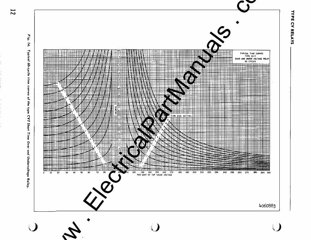
....... �
'11 �· � .... � ;;· 2.. 9 n
"< n ;;-... 3' ., n � ., "' 0 .... ... ::..,
:i ., () � " "" a :::. .... 3' ., 0 < ., .. Q :I a..
� t < 0 :;-.g ., :::0 Ill a�
\_)
11
10 20 30 �0
8
f./i! I I I I I Ill I I I Ill IIIlllTI I l l
[ �
112H'fi±±±il 112
8
7
11
10,
g
T I ME D I AL SETT ING
I I! I I I I I I I I I I I I I I I I I jj �0 60 70 80 90 100 1 10 120 130 1�0 150 160 170 180 190 200 210 220 230
PER CENT OF UP VALUE VOL TAG£
\J
TYPI CAL T I ME CURVES TYPE CV-7
OVER AND UNDU VOL TAG£ RELAY 60 CYCLES
2� 2!50 260 270 280 290 300
4o6c883
\L)
:J "'V m n < ;liD m .... ,.. -< CA www .
Elec
tricalP
artM
anua
ls . c
om
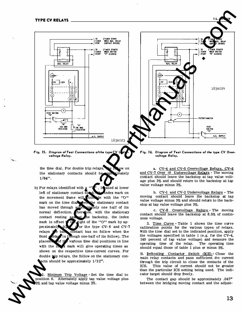
TYPE CV RELAYS
r (TIMER STOPS TIMER MIEN AUX. RElAY STOP CONTACT OPEIIS)
r ( TIMER STARTS TIMER MIEN S•l TCK START '$' CLOSES)
A. C. SUPPlY
l83A023
F ig. 15. Diagram of Test Connections ofthe type CV Unclerv6ltage Relay.
the time dial . For double trip relays, the foll ow on
the stationary contacts shoul d be approximately
1/64" .
b) For relays identified with a "T .. , located at lower
left of stationary contact block , the index mark on the movement fram e will coincide with the "0 .. mark on the time dial when the stationary contact has moved through approximately one h al f of its normal defl ection. Therefore , with the station ary contact resting against the backstop , the index
ma!k is offset to the ri ght of the "0" mark by appro xim ately .0 20". (For th e type CV· 6 and CV-7 relays the back contact has no fol lo w when th e front contact i s through one-half o f its follow) . Th e placem ent of the various time dial positions in line
with the index mark will give operatin g times as shown on the respective time- current curves. For
double trip rel ays, the follow on the stationary con
tacts should be approximately 113 2••,
2. Minimum Trip Voltage - Set the time dial to position 6. Alternately apply tap value voltage plus 3% and tap value voltage minus 3%.
I .L. 41-201F
ro ( TIMER SlliPS TI MER MIEN AUX. RELAY SlliP CONTACT OPENS) } �MER
( TI MER STARTS MIEll S•l TCK
START 'S' CLOSES)
l83A024
TEST S•I TCK •s•
�----ol-------+--o 't::: A,C, SUPPlY
F ig. 1 6. Diagram of Test Connections of the type CV Over• voltage Relay.
a. CV-4 and CV-5 Overvoltage Relays, CV-6 and CV-7 Over or Undervoltage Relays - The moving cont act should leave the backstop at tap value voltage plus 3% and should return to the backstop at tap value voltage minus 3%.
b. CV-1 and CV-2 Undervoltage Relays - The moving contact should leave the backstop at tap value voltage minus 3% and should return to the backstop at tap value voltage plus 3%.
c. CV-8 Overvoltage Rela,ys - The moving contact should leave the backstop at 8.5% of continuous voltage.
3. Time Curve - Table 1 shows the time curve calibration points for the various types of relays. With the time dial set to the indicated position, apply the voltages specified in table 1 (e. g. for the CV-4, 140 percent of tap value voltage) and measure the ope rating time of the relay. The operating time should equal those of table 1 plus or minus 5%.
B. Indicating Contactor Switch (ICS) - Close the main relay contacts and pass sufficient d-e current throug h the trip circuit to close the contacts of the ICS. This value of current should not be greater than the particular ICS setting being used. The indicator target should drop freely.
The contact gap should be approximately .047" between the bridging moving contact and the adjust-
13 www . El
ectric
alPar
tMan
uals
. com
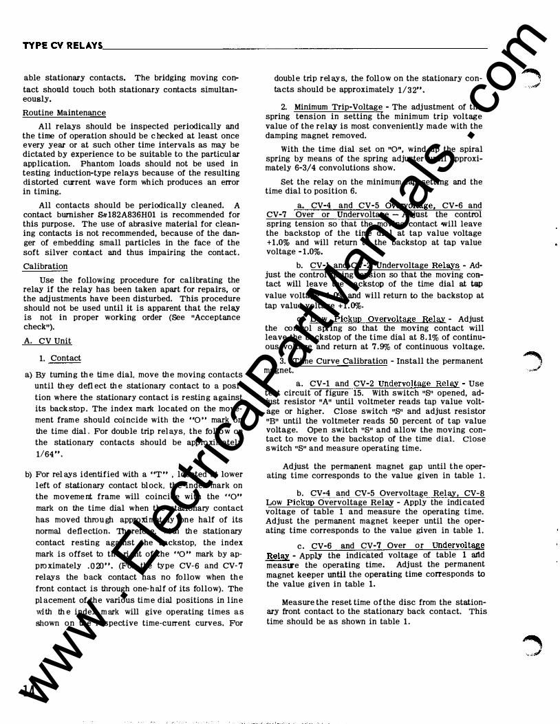
TYPE CV RELAYS. ________________________________________________________ ___
able stationary contacts. The bridging moving con
tact should touch both stationary contacts simultaneously.
Routine Maintenance
All relays should be inspected periodically and the time of operation should be c hecked at least once every year or at such other time intervals as may be dictated by experience to be suitable to the particular application. Phantom loads should not be used in testing induction-type relays because of the resulting di storted current wave form which produces an error in timing.
All contacts should be periodically cleaned. A contact burnisher SI/:182A836H01 is recommended for this purpose. The use of abrasive material for cleaning contacts is not recommended, because of the danger of embedding small particles in the face of the soft silver contact and thus impairing the contact .
Calibration
Use the following procedure for calibrating the relay if the relay has been taken apart for repairs, or the adj ustments have been disturbed. This procedure should not be used until it is apparent that the relay is not in proper working order (See "Acceptance check").
A. CV Unit
1. Contact
a) By turning th e tim e dial, move th e moving contacts until th ey defl ect th e stationary contact to a posi
tion where the stationary contact is restin g against its back stop . The index mark loc ated on the movement fram e should coincide with the "0" mark on
the time dial . For double trip rei ays, the foll o w on the stationary contacts should be app ro ximately
1/64 " .
b) For rel ays identified with a "T " , loc ated at lower left of stationary contact block, th e index mark on the moveme nt frame will coincide with the "0" mark on the time dial when the stationary contact
has moved throu gh approxi mately on e half of its
normal defl ection. Therefore, wi th th e station ary
contact resting against the backstop, the index
mark is offset to the ri ght of the "0 " mark by ap
pro ximately . O :D ". (For the type CV-6 and CV- 7
relays the back contact has no follow when th e
front contact is through one-half of its follow). The
pl acement of the various tim e dial positions in lin e
with th e index m ark will give operating times as shown on th e respective time-current curves. For
14
doubl e trip rel ay s, the foll ow on the stationary contacts should be approximately 1/32".
2. Minimum Trip-Voltage - The adjustment of the spring tension in setting the minimum trip voltage value of the relay is most conveniently made with the damping magnet removed.
With the time dial set on "0", wind up the spiral spring by means of the spring adjuster until approximately 6-3/4 convolutions show.
Set the relay on the minimum tap setting and the time dial to position 6.
a. CV-4 and CV-5 Overvoltage, CV-6 and CV-7 Over or Undervoltage - Adjust the control spring tension so that the moving contact will leave the backstop of the time dial at tap value voltage + 1 .0% and will return to the backstop at tap value voltage - 1 .0%.
b. CV-1 and CV-2 Undervoltage Relays - Adjust the control spring tension so that the moving contact will leave the backstop of the time dial at tap value voltage - 1 . 0% and will return to the backstop at tap value voltage +1.0%.
c. Low Pickup Overvoltage Relay - Adjust the control spring so that the moving contact will leave the backstop of the time dial at 8. 1% of continuous voltage and return at 7 .9% of continuous voltage.
3. Time Curve Calibration - Install the permanent magnet.
a. CV-1 and CV-2 Undervoltage Relay - Use test circuit of figure 15. With switch "8" opened, adjust resistor "A" until voltmeter reads tap value voltage or higher. Close switch "8" and adjust resistor "B" until the voltmeter reads 50 percent of tap value voltage. Open switch "8" and allow the moving contact to move to the backstop of the time dial. Close switch "8" and measure operating time.
Adjust the permanent magnet gap until the operating time corresponds to the value given in table 1 .
b. CV-4 and CV-5 Overvoltage Relay, CV-8 Low Pickup Overvoltage Relay - Apply the indicated voltage of table 1 and measure the operating time. Adjust the permanent magnet keeper until the operating time corresponds to the value given in table 1 .
c. CV-6 and CV-7 Over or Undervoltage Relay - Apply the indicated voltage of table 1 artd meas\l'e the operating time. Adjust the permanent magnet keeper until the operating time corresponds to the value given in table 1.
Measure the reset time of the disc from the stationary front contact to the stationary back contact. This time should be as shown in table 1 .
www . El
ectric
alPar
tMan
uals
. com
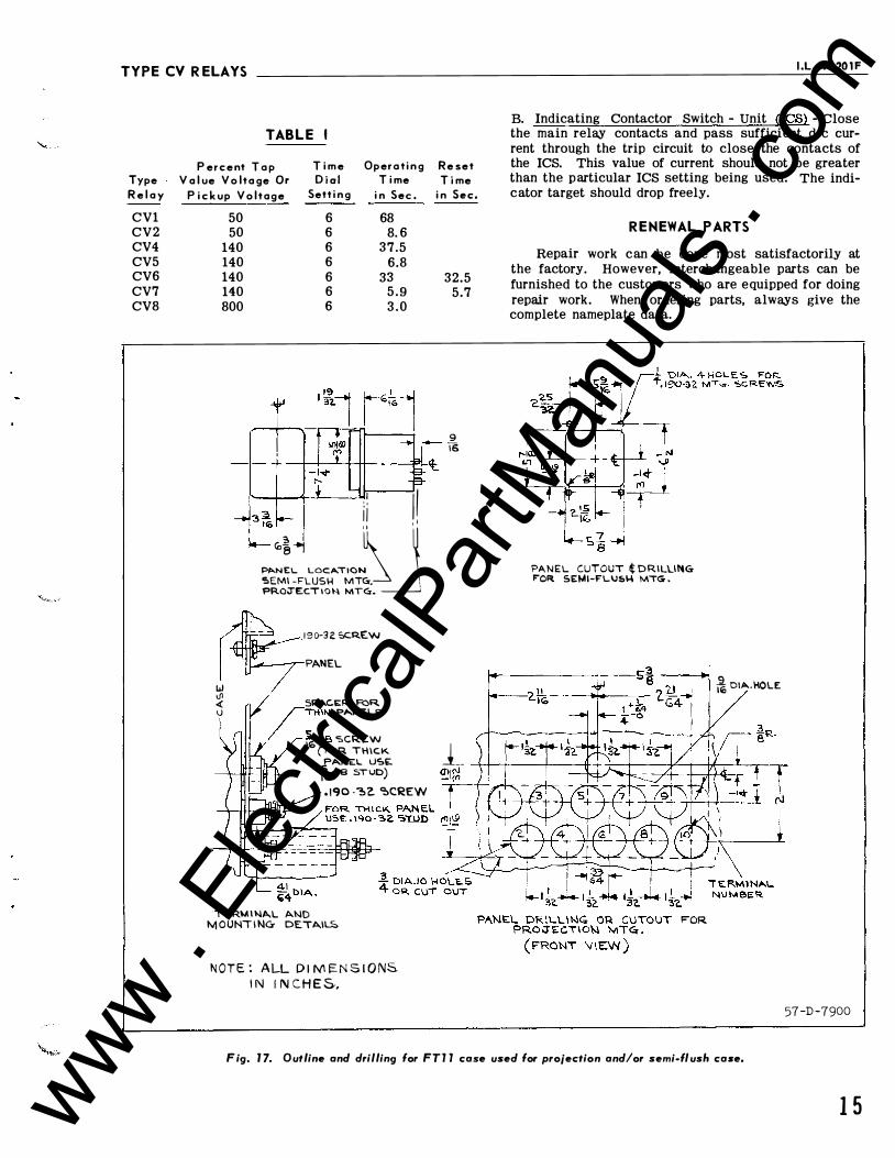
TYPE CV R ELAYS I .L. 41-20 1 F
Type R e l a y
CV1 CV2 CV4 CV5 CV6 CV7 CV8
TABLE I
P er c e nt T o p T i m e Ope r o t i n g R e set V a l ue V o lta ge Or D ia l T i me T i me
P i c k up V o l t a g e Sett i n g i n Sec . i n Sec.
50 50
140 140 140 140 800
6 6 6 6 6 6 6
68 8. 6
37.5 6.8
33 5 . 9 3 . 0
t .. � \!1 �! ! PI>.N:L LOCA.TI()N '!>EMI -FLUS\4 MTGr. , PROJ'ECT I 0 \-.1 MTGr. ______]
w \ll
1 9 o-n sc.R.E.w PANEL
..( 5PAC.ER FOR. U /THI"' P..._NEL'O
/ � :i - 1e ':.CREW
32.5 5.7
9 T6
B. Indicating Contactor Switch - Unit (ICS) - Close the main relay contacts and pass sufficient d-e current through the trip circuit to close the contacts of the ICS. This value of current should not be greater than the particular ICS setting being used. The indicator target should drop freely.
RENEWAL PARTS
Repair work can be done most satisfactorily at the factory. However, interchangeable parts can be furnished to the customers who are equipped for doing repair work. When ordering parts, always give the complete nameplate data.
PANEL CUTOUT t DRILUNGr F'OR SEMI-FLU�\-\ MTG .
9 � 011>-.HOLE
16 ( f"OR THICK 1 f""NEL USE __ ----.jt-+--+---l---4 1,.,- ta !:.TUO) .190 -�z �CREW
TC:RMI "'AL AND M OUNT I NG- DETAIL!:.
N O T E : A LL D l M I=.N S I O NS. I N I N C H E S,,
FOR
F ig. 1 7. Outline and drilling for FT l l case used for projection and/or semi-flush case.
57-D-7900
1 5 www . El
ectric
alPar
tMan
uals
. com
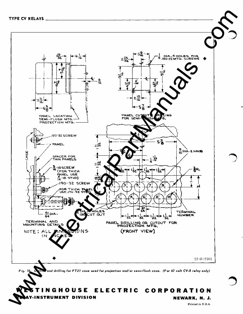
TYPECVRELAYS ______________________________________________________ ___
&..------- . tc;:,0-32. SC.RE.W � � PANEL ' w � SPACER FOR 0 T\-IIN PANELS
.fl -IB SCRE.W 16 (rOR. 11·\IC\o<.. �NEL USE 16- 18 O:.TUD) . ! CJ0 · '3'2. SCREW
TERMIN�L �N D 1-1\0\..lNTI N q Ot:'T,._I\ ... � N O T E : A L L D I M E N5 \ 0 N S I N I N C H E S
! 01 ..... . 4- HOLES ¥"OR + . te0-31. MTC:r. SCREW$
PANEL CUTOUT 4 DR.ILL\ WG�OR. SEMI-F \..U5\-I MTG.
I 'i"l.. ?AWE\.. CR\L\...\ NG- OR. CUTOUT PROJ"E.C.T\ON MTG.
(rRO)..lT V\E.W)
57 -D -7901
Fig. 78. Outline and drilling for FT2 1 case used for projection and/or semi-flush case. (For 67 volt CV-8 relay only)
W ESTINGHOUSE ELECTR I C R E LAY- I N STRU M E NT D IVI S I O N
COR P OR A T ION N E WARK, N. J.
Printed in U.S.A. www . El
ectric
alPar
tMan
uals
. com