Embed Size (px)
Citation preview
®
CU-119
July 10, 2018
e x i d a F M E D AS I L 3
DESCRIPTION The Fireye Phoenix Series 2 type 85UVF/IRF flame scanners are microprocessor based devices utilizing a solid state flame detection sensor. The Phoenix flame scanners incorporate an internal flame relay with automatically set ON/OFF thresholds, thereby eliminating the need for a remote flame amplifier or flame switch. Phoenix scanners detect the amplitude of the modulations (the flame “flicker”) that occur within the tar-geted flame, over a wide frequency. During the scanner setup procedure, the amplitudes of the target flame are automatically stored by the flame scanner, together with optimum ON/OFF criteria. The appro-priate sensor gain is automatically selected. Phoenix scanners incorporate full self-diagnostics and elec-tronic self-checking.
The Phoenix 85UVF/IRF is available in multiple models differentiated by spectral range, levels of hazard-ous area certifications and agency approvals. Refer to Table 1 on page 3 for an overview of model num-bers versus product certifications.
The Phoenix 85UVF/IRF flame scanner is powered by 24Vdc. Electrical connection is via an 8-pin elec-trical quick-disconnect (QD). An analog 4 to 20mA output of flame strength is standard. Note: The Phoenix QD models with electrical quick-disconnect have replaced the original models equipped with ten feet of captive cable. The QD models (with 59-546-x cables) are suitable for use in Class I Division 2 hazardous areas, thereby eliminating the need for “EX” models. The “CEX” models remain unchanged for use in Ex II 2 G/D hazardous areas.
Important: When a Phoenix Series 2 scanner replaces an older generation Phoenix scanner (e.g., 85UVF1-1EX, 85IRF1-1QD), the mounting flange must also be replaced.
APPLICATION Fireye Phoenix 85UVF self-checking scanners are used to detect 295 to 340 nanometers wavelength ultra-violet emissions. The Fireye Phoenix 85UVF1A-1QDK3 and 85UVF1A-1CEX-K3 Flame Scanners are derivatives of the standard Phoenix product but utilizing an advanced optical filter. This filter adjusts the optical sensitivity of the detection cell to pick up wavelengths of light from the standard 310 nm range up to 500 nm.
Typical Applications: Duct Burners, Industrial Gas Burners, Refinery Applications, Low NOx Burners, Waste Gas Units and Incinerators. The K3 scanner is particularly suited to measure the light emissions from steel plant applications such as burners firing blast furnace gas and coke oven gas.
Fireye Phoenix 85IRF self-checking scanners are used to detect 830 to 1100 nanometers wavelength infrared emissions. They are suited for application to duct burners, industrial gas burners, refinery applications ignition systems and Low NOx detection and for continuous or non-continuous burner operation.
Typical Applications: Duct Burners, Industrial Oil Burners, Refinery Applications, Waste Oil Units and Incinerators. NOTE: Because the sensors in the Phoenix are solid state devices they can perform well with many different fuels. For example UV is typically used on gaseous fuels but can also be applied to oils and heavy oils. To be 100% sure of correct application a test should be performed.
We DO NOT recommend the Phoenix scanner for use on small pilot flames or obstructed sighting.
OPERATOR & SYSTEM INTERFACE
Operator interface to the Phoenix scanner is via a pushbutton keypad and informative LEDs. These pro-vide continuous indication of flame signal, flame relay status, scanner status as well as selected mode of operation. Simplified keystroke routines are used for setup and this can be completed in seconds. For remote interface, outputs are provided for flame switch, fault relay and 4 to 20mA flame strength.
1
TYPE 85UVF/IRF Integrated Flame Scanner with Internal Flame Relay
See table on page 3
SPECIFICATIONS
FIGURE 1. DIMENSIONS
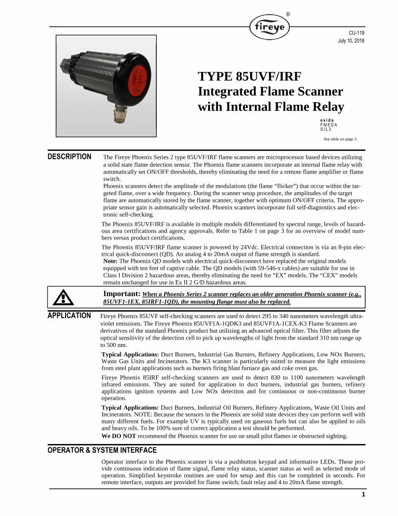
FIGURE 2. PHOENIX SCANNER in ATEX HAZARDOUS AREA HOUSING (mounting flange kit ordered separately)
All models of the Phoenix 85UVF1/IRF1-1CEX and 85UVF1-1CEX-K3 flame scanners are housed within an ATEX approved housing for application in Ex II 2 G/D hazardous rated environment. In addition the ATEX housing is designed to meet the requirements of IP66 (NEMA 4X).
2
®
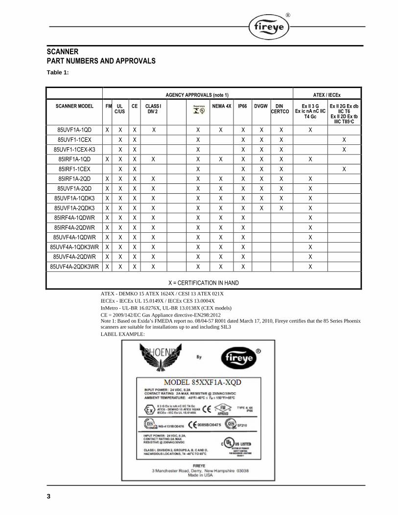
SCANNER PART NUMBERS AND APPROVALS
Table 1:
AGENCY APPROVALS (note 1) ATEX / IECEx
SCANNER MODEL FM UL C/US
CE CLASS I DIV 2
NEMA 4X IP66 DVGW DIN CERTCO
Ex II 3 G Ex ic nA nC IIC
T4 Gc
Ex II 2G Ex db IIC T6
Ex II 2D Ex tb IIIC T85oC
85UVF1A-1QD X X X X X X X X X X
85UVF1-1CEX X X X X X X X
85UVF1-1CEX-K3 X X X X X X X
85IRF1A-1QD X X X X X X X X X X
85IRF1-1CEX X X X X X X X
85IRF1A-2QD X X X X X X X X X X
85UVF1A-2QD X X X X X X X X X X
85UVF1A-1QDK3 X X X X X X X X X X
85UVF1A-2QDK3 X X X X X X X X X X
85IRF4A-1QDWR X X X X X X X X
85IRF4A-2QDWR X X X X X X X X
85UVF4A-1QDWR X X X X X X X X
85UVF4A-1QDK3WR X X X X X X X X
85UVF4A-2QDWR X X X X X X X X
85UVF4A-2QDK3WR X X X X X X X X
X = CERTIFICATION IN HAND
ATEX - DEMKO 15 ATEX 1624X / CESI 13 ATEX 021X
IECEx - IECEx UL 15.0149X / IECEx CES 13.0004X
InMetro - UL-BR 16.0276X, UL-BR 13.0138X (CEX models)
CE = 2009/142/EC Gas Appliance directive-EN298:2012 Note 1: Based on Exida’s FMEDA report no. 08/04-57 R001 dated March 17, 2010, Fireye certifies that the 85 Series Phoenix scanners are suitable for installations up to and including SIL3
LABEL EXAMPLE:
3
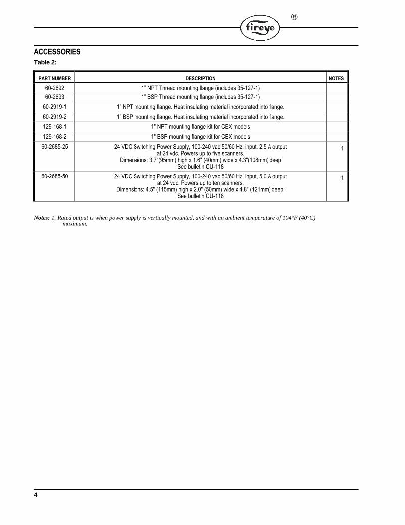
ACCESSORIES Table 2:
PART NUMBER DESCRIPTION NOTES
60-2692 1” NPT Thread mounting flange (includes 35-127-1) 60-2693 1” BSP Thread mounting flange (includes 35-127-1)
60-2919-1 1” NPT mounting flange. Heat insulating material incorporated into flange. 60-2919-2 1” BSP mounting flange. Heat insulating material incorporated into flange. 129-168-1 1" NPT mounting flange kit for CEX models 129-168-2 1" BSP mounting flange kit for CEX models 60-2685-25 24 VDC Switching Power Supply, 100-240 vac 50/60 Hz. input, 2.5 A output
at 24 vdc. Powers up to five scanners. Dimensions: 3.7"(95mm) high x 1.6" (40mm) wide x 4.3"(108mm) deep
See bulletin CU-118
1
60-2685-50 24 VDC Switching Power Supply, 100-240 vac 50/60 Hz. input, 5.0 A output at 24 vdc. Powers up to ten scanners.
Dimensions: 4.5" (115mm) high x 2.0" (50mm) wide x 4.8" (121mm) deep. See bulletin CU-118
1
Notes: 1. Rated output is when power supply is vertically mounted, and with an ambient temperature of 104°F (40°C) maximum.
4
®
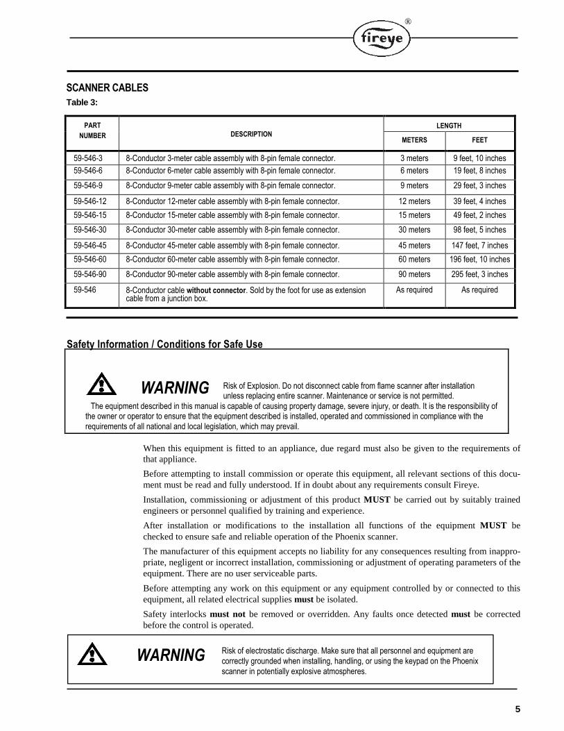
SCANNER CABLES Table 3:
PART
NUMBER DESCRIPTION LENGTH
METERS FEET
59-546-3 8-Conductor 3-meter cable assembly with 8-pin female connector. 3 meters 9 feet, 10 inches
59-546-6 8-Conductor 6-meter cable assembly with 8-pin female connector. 6 meters 19 feet, 8 inches
59-546-9 8-Conductor 9-meter cable assembly with 8-pin female connector. 9 meters 29 feet, 3 inches
59-546-12 8-Conductor 12-meter cable assembly with 8-pin female connector. 12 meters 39 feet, 4 inches
59-546-15 8-Conductor 15-meter cable assembly with 8-pin female connector. 15 meters 49 feet, 2 inches
59-546-30 8-Conductor 30-meter cable assembly with 8-pin female connector. 30 meters 98 feet, 5 inches
59-546-45 8-Conductor 45-meter cable assembly with 8-pin female connector. 45 meters 147 feet, 7 inches
59-546-60 8-Conductor 60-meter cable assembly with 8-pin female connector. 60 meters 196 feet, 10 inches
59-546-90 8-Conductor 90-meter cable assembly with 8-pin female connector. 90 meters 295 feet, 3 inches
59-546 8-Conductor cable without connector. Sold by the foot for use as extension cable from a junction box.
As required As required
Safety Information / Conditions for Safe Use
WARNING Risk of Explosion. Do not disconnect cable from flame scanner after installation unless replacing entire scanner. Maintenance or service is not permitted.
The equipment described in this manual is capable of causing property damage, severe injury, or death. It is the responsibility of the owner or operator to ensure that the equipment described is installed, operated and commissioned in compliance with the requirements of all national and local legislation, which may prevail.
When this equipment is fitted to an appliance, due regard must also be given to the requirements of that appliance.
Before attempting to install commission or operate this equipment, all relevant sections of this docu-ment must be read and fully understood. If in doubt about any requirements consult Fireye.
Installation, commissioning or adjustment of this product MUST be carried out by suitably trained engineers or personnel qualified by training and experience.
After installation or modifications to the installation all functions of the equipment MUST be checked to ensure safe and reliable operation of the Phoenix scanner.
The manufacturer of this equipment accepts no liability for any consequences resulting from inappro-priate, negligent or incorrect installation, commissioning or adjustment of operating parameters of the equipment. There are no user serviceable parts.
Before attempting any work on this equipment or any equipment controlled by or connected to this equipment, all related electrical supplies must be isolated.
Safety interlocks must not be removed or overridden. Any faults once detected must be corrected before the control is operated.
WARNING Risk of electrostatic discharge. Make sure that all personnel and equipment are correctly grounded when installing, handling, or using the keypad on the Phoenix scanner in potentially explosive atmospheres.
5
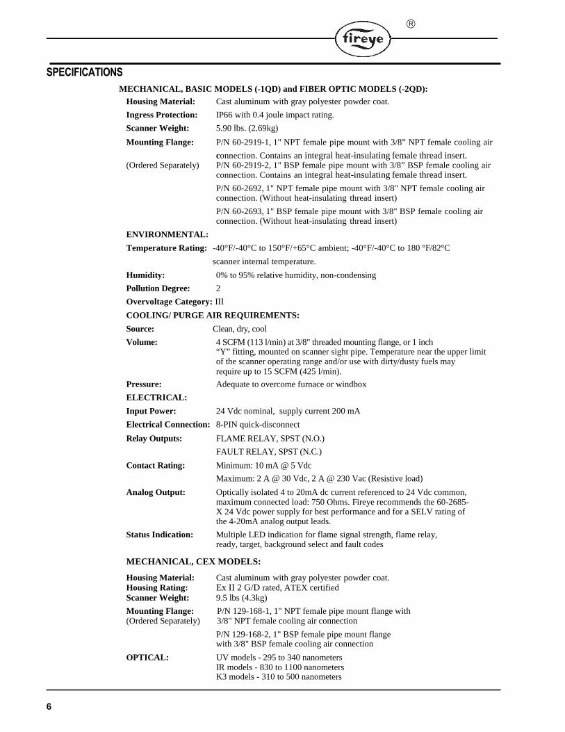
SPECIFICATIONS
MECHANICAL, BASIC MODELS (-1QD) and FIBER OPTIC MODELS (-2QD):
Housing Material: Cast aluminum with gray polyester powder coat.
Ingress Protection: IP66 with 0.4 joule impact rating.
Scanner Weight: 5.90 lbs. (2.69kg)
Mounting Flange: P/N 60-2919-1, 1" NPT female pipe mount with 3/8” NPT female cooling air
connection. Contains an integral heat-insulating female thread insert.(Ordered Separately) P/N 60-2919-2, 1" BSP female pipe mount with 3/8” BSP female cooling air
connection. Contains an integral heat-insulating female thread insert.
P/N 60-2692, 1" NPT female pipe mount with 3/8" NPT female cooling air connection. (Without heat-insulating thread insert)
P/N 60-2693, 1" BSP female pipe mount with 3/8" BSP female cooling air connection. (Without heat-insulating thread insert)
ENVIRONMENTAL:
Temperature Rating: -40°F/-40°C to 150°F/+65°C ambient; -40°F/-40°C to 180 °F/82°C
scanner internal temperature.
Humidity: 0% to 95% relative humidity, non-condensing
Pollution Degree: 2
Overvoltage Category: III
COOLING/ PURGE AIR REQUIREMENTS:
Source: Clean, dry, cool
Volume: 4 SCFM (113 l/min) at 3/8" threaded mounting flange, or 1 inch“Y” fitting, mounted on scanner sight pipe. Temperature near the upper limit of the scanner operating range and/or use with dirty/dusty fuels may require up to 15 SCFM (425 l/min).
Pressure: Adequate to overcome furnace or windbox
ELECTRICAL:
Input Power: 24 Vdc nominal, supply current 200 mA
Electrical Connection: 8-PIN quick-disconnect
Relay Outputs: FLAME RELAY, SPST (N.O.)
FAULT RELAY, SPST (N.C.)
Contact Rating: Minimum: 10 mA @ 5 Vdc
Maximum: 2 A @ 30 Vdc, 2 A @ 230 Vac (Resistive load)
Analog Output: Optically isolated 4 to 20mA dc current referenced to 24 Vdc common, maximum connected load: 750 Ohms. Fireye recommends the 60-2685-X 24 Vdc power supply for best performance and for a SELV rating of the 4-20mA analog output leads.
Status Indication: Multiple LED indication for flame signal strength, flame relay, ready, target, background select and fault codes
MECHANICAL, CEX MODELS:
Housing Material: Cast aluminum with gray polyester powder coat. Housing Rating: Ex II 2 G/D rated, ATEX certified Scanner Weight: 9.5 lbs (4.3kg)
Mounting Flange: P/N 129-168-1, 1" NPT female pipe mount flange with(Ordered Separately) 3/8" NPT female cooling air connection
P/N 129-168-2, 1" BSP female pipe mount flange with 3/8" BSP female cooling air connection
OPTICAL: UV models - 295 to 340 nanometersIR models - 830 to 1100 nanometers K3 models - 310 to 500 nanometers
6
®
CABLE SPECIFICATION:
Specification: P/N 59-546:
Multi-core, 8 conductor (color coded), with foil wrap and overall braided shield. PLTC-ER rating
Eight #18 AWG
Temperature Rating: -40° F to +221°F (-40°C to +105°C)
Cable Jacket: PVC
Nominal O.D. 0.44" (11.2 mm)
Maximum O.D. 0.48" (12.2 mm)
INSTALLATION NOTES
The Phoenix flame scanners determine the presence or absence of flame by monitoring the amplitude of the flame across a wide flicker frequency spectrum. The scanner should initially be mounted so that the primary combustion zone is within the scanner’s line of sight.
The location and sighting instructions listed in the following sections are rough guidelines for the location of the scanner. The scanner provides feedback via LEDs and the 4-20ma output to assist in the adjustment and proper alignment of the flame scanner. Refer to the set-up procedures described in this bulletin.
Note: An acceptable scanner location must ensure the following:
Reliable main flame and/or igniter flame detection at all air flow and furnace loads (ranges of fuel firing).
Rejection of the igniter flame if too short or in the wrong position to ignite the main flame reliably, thus is prohibiting the delivery of fuel to the burner.
Note: Ensure the correct FFRT (Flame Failure Response Time) is selected prior to commissioning.
INSTALLATION PROCEDURE
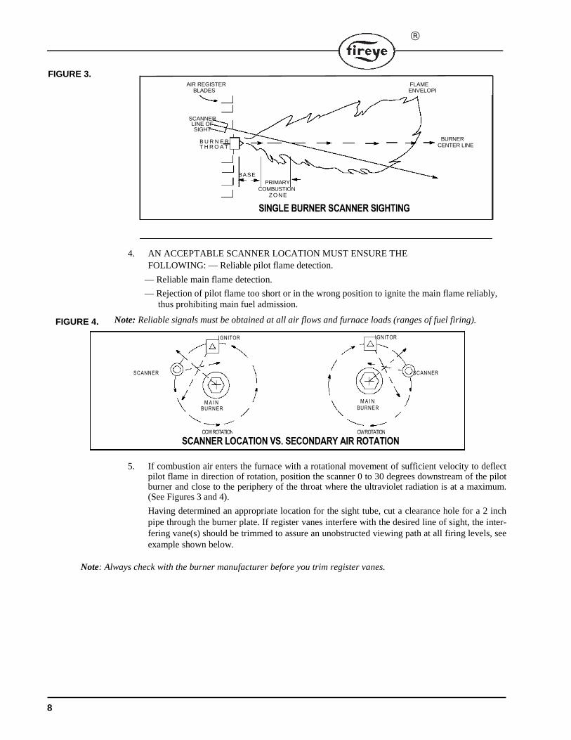
1. The best results are obtained when the scanner is aimed so that the scanner’s line of sight inter-sects the burner center at a slight angle (e.g. 5 degrees) and sees a maximum of the primary combustion zone, as shown in Figure 3. If only one scanner is used per burner, the line of sight should also intersect the igniting flame.
2. For installations where separate scanners are used to monitor main and igniter flames, the main flame scanner should be sighted so it does not detect the igniter flame.
3. The scanner should have an unrestricted view of flame as far as possible. Physical obstructions such as air register blades, interfering vanes, or other hardware should be cut away or notched so they do not fall within the scanner’s line of sight as shown in Figure 3.
Note: Always check with the burner manufacturer before you trim the register blades.Note: When installing flange 35-318-1 or 35-318-2, only torque to 60 in/lbs. (5 ft./lbs. or 6.8Nm) on the sight pipe or damage can occur. (Hand tight plus 1 turn max)
7
WARNING: Protective filtered lenses should be worn when viewing flame; infrared and ultraviolet energy from the flame can be damaging to the eyes.
WARNING – All installation, service and troubleshooting of Fireye products must be performed
AIR REGISTER FLAMEBLADES ENVELOPE
SCANNER LINE OF SIGHT
B U R N E R T H R O A T
BASE
PRIMARY COMBUSTION
SINGLE BURNER SCANNER SIGHTING
Z O NE
BURNER CENTER LINE
SCANNER
SCANNER LOCATION VS. SECONDARY AIR ROTATIONCCW ROTATION
BURNERM A I N
IGNITOR
CW ROTATION
BURNERM A I N
IGNITOR
SCANNER
FIGURE 3.
4. AN ACCEPTABLE SCANNER LOCATION MUST ENSURE THE
FOLLOWING: — Reliable pilot flame detection.
— Reliable main flame detection.
— Rejection of pilot flame too short or in the wrong position to ignite the main flame reliably, thus prohibiting main fuel admission.
Note: Reliable signals must be obtained at all air flows and furnace loads (ranges of fuel firing).
5. If combustion air enters the furnace with a rotational movement of sufficient velocity to deflect pilot flame in direction of rotation, position the scanner 0 to 30 degrees downstream of the pilot burner and close to the periphery of the throat where the ultraviolet radiation is at a maximum. (See Figures 3 and 4).
Having determined an appropriate location for the sight tube, cut a clearance hole for a 2 inch pipe through the burner plate. If register vanes interfere with the desired line of sight, the inter-fering vane(s) should be trimmed to assure an unobstructed viewing path at all firing levels, see example shown below.
Note: Always check with the burner manufacturer before you trim register vanes.
8
FIGURE 4.
®
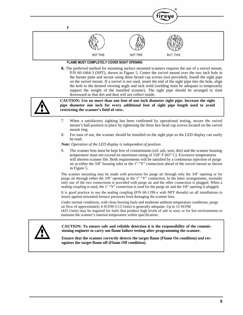
NOT THIS NOT THIS BUT THIS
F
FLAME MUST COMPLETELY COVER SIGHT OPENING
6. The preferred method for mounting surface mounted scanners requires the use of a swivel mount, P/N 60-1664-3 (NPT), shown in Figure 5. Center the swivel mount over the two inch hole in the burner plate and secure using three hexed cap screws (not provided). Install the sight pipe on the swivel mount. If a swivel is not used, insert the end of the sight pipe into the hole, align the hole to the desired viewing angle and tack weld (welding must be adequate to temporarily support the weight of the installed scanner). The sight pipe should be arranged to slant downward so that dirt and dust will not collect inside.
CAUTION: Use no more than one foot of one inch diameter sight pipe. Increase the sight pipe diameter one inch for every additional foot of sight pipe length used to avoid restricting the scanner’s field of view.
7. When a satisfactory sighting has been confirmed by operational testing, secure the swivel mount’s ball position in place by tightening the three hex head cap screws located on the swivel mount ring.
8. For ease of use, the scanner should be installed on the sight pipe so the LED display can easily be read.
Note: Operation of the LED display is independent of position.
9. The scanner lens must be kept free of contaminants (oil, ash, soot, dirt) and the scanner housing temperature must not exceed its maximum rating of 150° F (65° C). Excessive temperatures will shorten scanner life. Both requirements will be satisfied by a continuous injection of purge air at either the 3/8" housing inlet or the 1" “Y” connection ahead of the swivel mount as shown in Figure 5.
The scanner mounting may be made with provision for purge air through only the 3/8" opening or for purge air through either the 3/8" opening or the 1" “Y” connection. In the latter arrangements, normally only one of the two connections is provided with purge air and the other connection is plugged. When a sealing coupling is used, the 1" “Y” connection is used for the purge air and the 3/8" opening is plugged.
It is good practice to use the sealing coupling (P/N 60-1199-x with NPT threads) on all installations to insure against unwanted furnace pressures from damaging the scanner lens.
Under normal conditions, with clean burning fuels and moderate ambient temperature conditions, purge air flow of approximately 4 SCFM (113 l/min) is generally adequate. Up to 15 SCFM (425 l/min) may be required for fuels that produce high levels of ash or soot, or for hot environments to maintain the scanner’s internal temperature within specification.
CAUTION: To ensure safe and reliable detection it is the responsibility of the commis-sioning engineer to carry out flame failure testing after programming the scanner.
Ensure that the scanner correctly detects the target flame (Flame On condition) and rec-ognizes the target flame off (Flame Off condition).
9
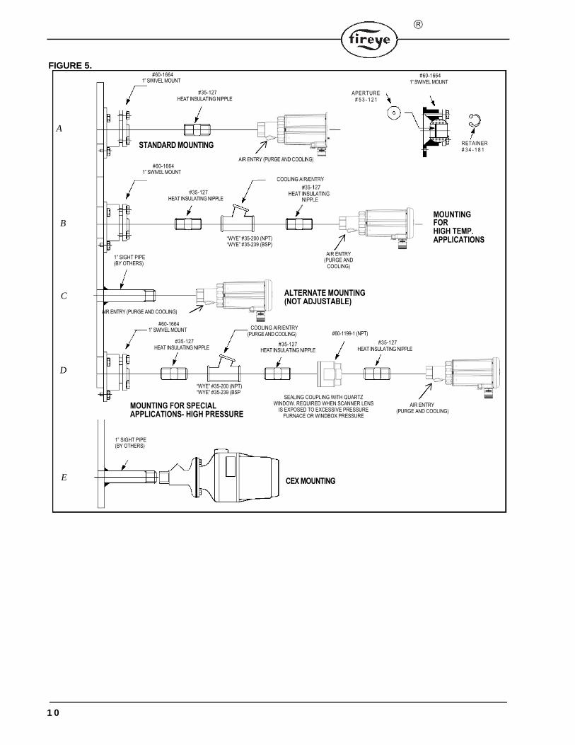
FIGURE 5.
1” SIGHT PIPE (BY OTHERS)
AIR ENTRY (PURGE AND COOLING)
#60-16641” SWIVEL MOUNT
#35-127HEAT INSULATING NIPPLE
“WYE” #35-200 (NPT) “WYE” #35-239 (BSP
MOUNTING FOR SPECIAL APPLICATIONS- HIGH PRESSURE
SEALING COUPLING WITH QUARTZ WINDOW. REQUIRED WHEN SCANNER LENS
IS EXPOSED TO EXCESSIVE PRESSURE FURNACE OR WINDBOX PRESSURE
MOUNTING FOR HIGH TEMP. APPLICATIONS
AIR ENTRY (PURGE AND COOLING)
D
COOLING AIR/ENTRY(PURGE AND COOLING)
#35-127HEAT INSULATING NIPPLE
A
#60-16641” SWIVEL MOUNT
B
AIR ENTRY (PURGE AND
COOLING)
C
COOLING AIR/ENTRY
#35-127 HEAT INSULATING
NIPPLE
#35-127HEAT INSULATING NIPPLE
“WYE” #35-200 (NPT) “WYE” #35-239 (BSP)
ALTERNATE MOUNTING (NOT ADJUSTABLE)
STANDARD MOUNTING
AIR ENTRY (PURGE AND COOLING)
#60-16641” SWIVEL MOUNT
#35-127HEAT INSULATING NIPPLE
#60-16641” SWIVEL MOUNT
APERTURE# 5 3 - 1 2 1
RETAINER# 3 4 - 1 8 1
1” SIGHT PIPE (BY OTHERS)
E CEX MOUNTING
#60-1199-1 (NPT)
#35-127HEAT INSULATING NIPPLE
1 0
®
A N A L O G O U T P U T 4 - 2 0 m A
PHOENIX 85UVF/IRF
INPUT POWER 2 4 V D C
F L A M E R E L A Y(Note 1)
F A U L T R E L A Y(Note 2)
F A U L T R E L A Y(Note 2)
(NOTE 6)
(+)
(-)
(+)
(-)
SHIELDQUICK-DISCONNECT PIN NUMBER
FIREYE 59-546-X CABLE
3
5
8
2
6
7
4
1
(NOTE 5)
BLACK (+)
VIOLET
ORANGE
YELLOW
RED
T A N
B L U E ( - )
BROWN
CHASSIS
+
TO BMS
INPUT (NOTES 3 & 4)
TO BMS INPUT (NOTES 3, 7 & 8)
TO BMS
INPUT (NOTES 3 & 4)
24VDC F I R E Y E 6 0 - 2 6 8 5 P O W E R S U P P L Y
GROUND
EARTH
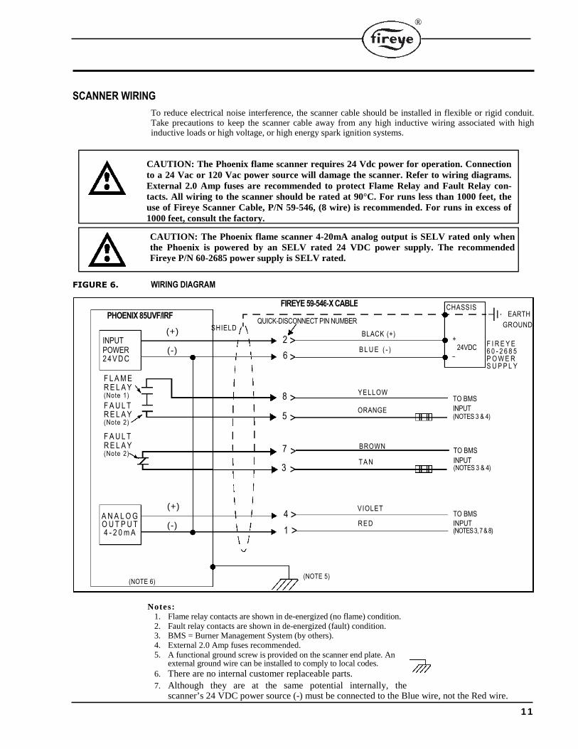
SCANNER WIRING
To reduce electrical noise interference, the scanner cable should be installed in flexible or rigid conduit. Take precautions to keep the scanner cable away from any high inductive wiring associated with high inductive loads or high voltage, or high energy spark ignition systems.
CAUTION: The Phoenix flame scanner requires 24 Vdc power for operation. Connection to a 24 Vac or 120 Vac power source will damage the scanner. Refer to wiring diagrams. External 2.0 Amp fuses are recommended to protect Flame Relay and Fault Relay con-tacts. All wiring to the scanner should be rated at 90°C. For runs less than 1000 feet, the use of Fireye Scanner Cable, P/N 59-546, (8 wire) is recommended. For runs in excess of 1000 feet, consult the factory.
CAUTION: The Phoenix flame scanner 4-20mA analog output is SELV rated only when the Phoenix is powered by an SELV rated 24 VDC power supply. The recommended Fireye P/N 60-2685 power supply is SELV rated.
FIGURE 6. WIRING DIAGRAM
Notes: 1. Flame relay contacts are shown in de-energized (no flame) condition. 2. Fault relay contacts are shown in de-energized (fault) condition. 3. BMS = Burner Management System (by others). 4. External 2.0 Amp fuses recommended. 5. A functional ground screw is provided on the scanner end plate. An
external ground wire can be installed to comply to local codes. 6. There are no internal customer replaceable parts.
7. Although they are at the same potential internally, the scanner’s 24 VDC power source (-) must be connected to the Blue wire, not the Red wire.
1 1
>
>
>
>
>
>
>
>
-
8 CONDUCTOR CABLE FEMALE END VIEW
8 (YELLOW)
4
(TAN)
5(BLACK) (ORANGE)
(VIOLET)
2
(RED) 7 (BLUE)
(BROWN)
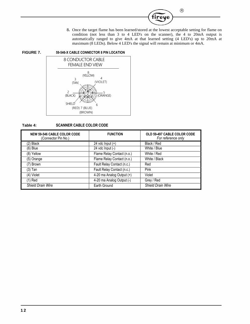
8. Once the target flame has been learned/stored at the lowest acceptable setting for flame on condition (not less than 3 to 4 LED's on the scanner), the 4 to 20mA output is automatically ranged to give 4mA at that learned setting (4 LED's) up to 20mA at maximum (8 LEDs). Below 4 LED's the signal will remain at minimum or 4mA.
FIGURE 7. 59-546-X CABLE CONNECTOR 8 PIN LOCATION
Table 4: SCANNER CABLE COLOR CODE
NEW 59-546 CABLE COLOR CODE (Connector Pin No.)
FUNCTION OLD 59-497 CABLE COLOR CODE For reference only
(2) Black 24 vdc Input (+) Black / Red(6) Blue 24 vdc Input (-) White / Blue
(8) Yellow Flame Relay Contact (n.o.) White / Red
(5) Orange Flame Relay Contact (n.o.) White / Black
(7) Brown Fault Relay Contact (n.c.) Red
(3) Tan Fault Relay Contact (n.c.) Pink
(4) Violet 4-20 ma Analog Output (+) Violet
(1) Red 4-20 ma Analog Output (-) Grey / Red
Shield Drain Wire Earth Ground Shield Drain Wire
1 2
SHIELD 6
3
®
T B1
T B 2
4 3 2 1
1 2 3 4
INTERNAL FACTORY WIRING
(KEYPAD END OF SCANNER)
(KEYPAD END OF SCANNER)
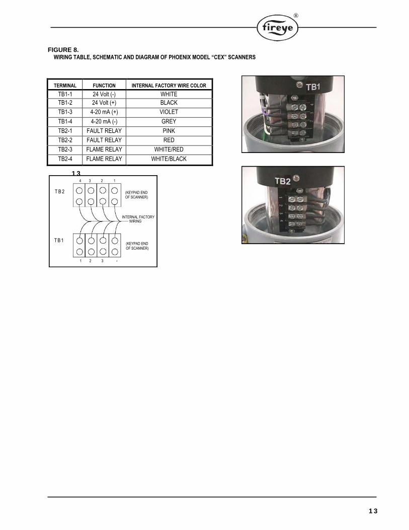
FIGURE 8.WIRING TABLE, SCHEMATIC AND DIAGRAM OF PHOENIX MODEL “CEX” SCANNERS
TERMINAL FUNCTION INTERNAL FACTORY WIRE COLOR
TB1-1 24 Volt (-) WHITE
TB1-2 24 Volt (+) BLACK
TB1-3 4-20 mA (+) VIOLET
TB1-4 4-20 mA (-) GREY
TB2-1 FAULT RELAY PINK
TB2-2 FAULT RELAY RED
TB2-3 FLAME RELAY WHITE/RED
TB2-4 FLAME RELAY WHITE/BLACK
1 3
1 3
FLAME STRENGTH
READY FLAME ON/OFF
READY FLAME
BACKGROUND FLAME SELECT
LEARN BACKGROUND FLAME
TARGET FLAME SELECT
LEARN TARGET FLAME
BASIC PROGRAMMING AND OPERATION
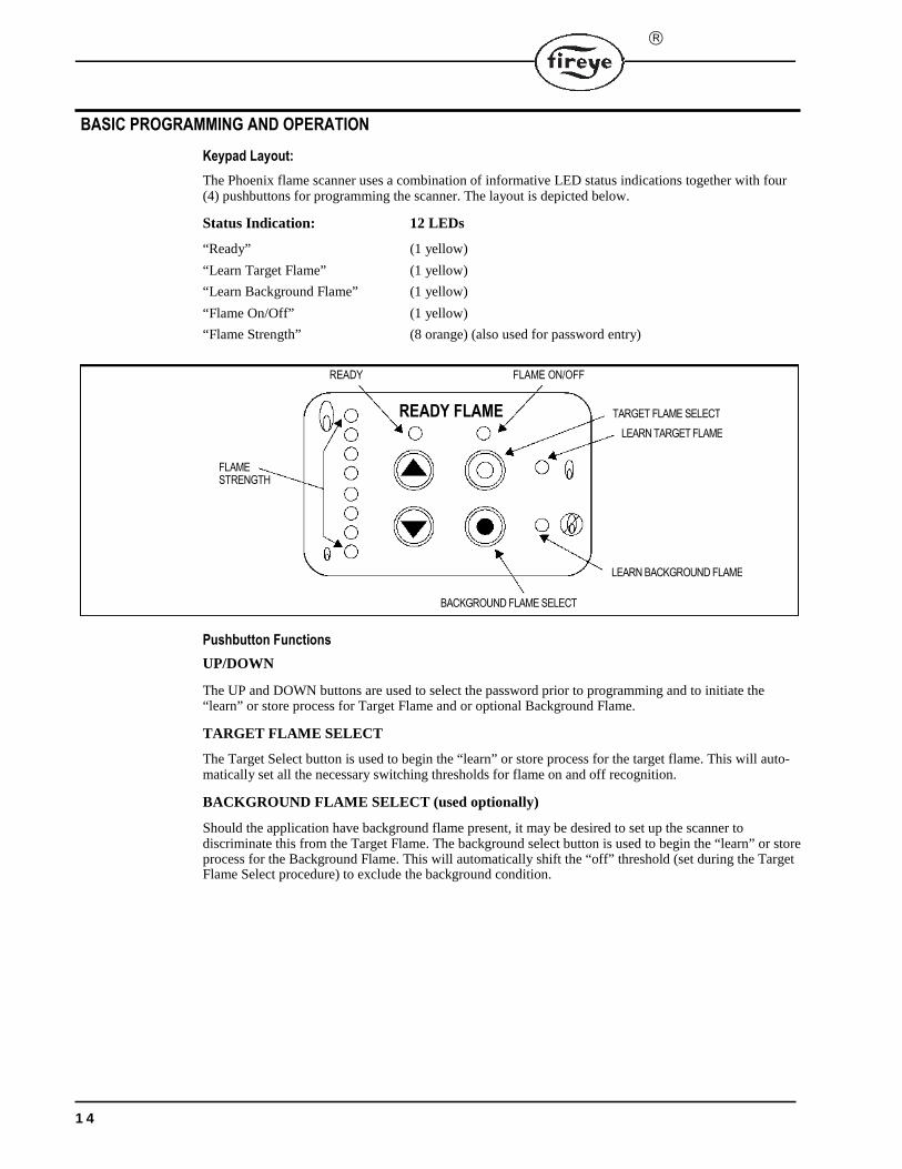
Keypad Layout:
The Phoenix flame scanner uses a combination of informative LED status indications together with four (4) pushbuttons for programming the scanner. The layout is depicted below.
Status Indication: 12 LEDs
“Ready” (1 yellow)
“Learn Target Flame” (1 yellow)
“Learn Background Flame” (1 yellow)
“Flame On/Off” (1 yellow)
“Flame Strength” (8 orange) (also used for password entry)
Pushbutton Functions
UP/DOWN
The UP and DOWN buttons are used to select the password prior to programming and to initiate the “learn” or store process for Target Flame and or optional Background Flame.
TARGET FLAME SELECT
The Target Select button is used to begin the “learn” or store process for the target flame. This will auto- matically set all the necessary switching thresholds for flame on and off recognition.
BACKGROUND FLAME SELECT (used optionally)
Should the application have background flame present, it may be desired to set up the scanner to discriminate this from the Target Flame. The background select button is used to begin the “learn” or store process for the Background Flame. This will automatically shift the “off” threshold (set during the Target Flame Select procedure) to exclude the background condition.
1 4
®
READY FLAME
= OFF
= ON
= FLASHING
P
Pre-Commissioning Settings
FFRT Set-Up Description
Using the keypad the scanner flame failure response time can be set by the user to the desired timing. Each unit comes from the factory preset at 1 second. To change the factory default to a different FFRT, see Set-Up Procedure below. To verify the current FFRT setting, press and hold the UP push button with the scanner in the normal operating mode. The “flame strength” LED set will display 1st, 2nd, 3rd or 4th LED as appropriate and these correspond to the FFRT in seconds.
FFRT Set-Up Procedure
If the Flame Failure Response Time needs modifying, follow the procedure listed below.
Press both the Target Flame Select and Background Flame Select buttons simultaneously.
Use the up button to drive the LEDs until LED number [8] (pass code) is illuminated on the flame strength LEDs right hand set.
Press both the Target Flame Select and Background Flame Select buttons simultaneously.
Press UP or DOWN push buttons to select required FFRT (the selected FFRT is displayed on the
flame strength LEDs as either 1st, 2nd, 3rd or 4th). Once you have selected the correct value, Press both
the Target Flame Select and Background Flame Select buttons simultaneously to store. The stored
value can be displayed and checked at any time while in the normal run mode. Pressing and holding
the UP pushbutton at any time will display the stored FFRT on the flame LEDs right hand set. Verify
that the correct FFRT has been stored.
Commissioning the Scanner /Learning the Flame Condition
Step 1 – Enter the pass code
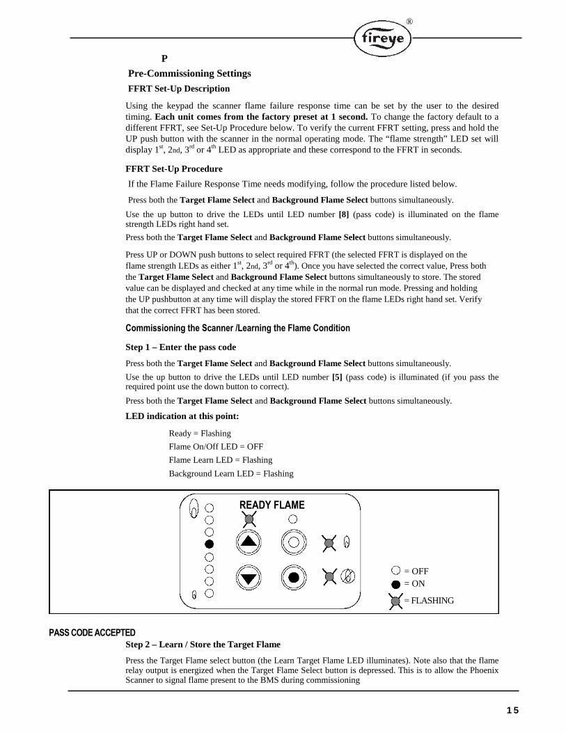
Press both the Target Flame Select and Background Flame Select buttons simultaneously.
Use the up button to drive the LEDs until LED number [5] (pass code) is illuminated (if you pass the required point use the down button to correct).
Press both the Target Flame Select and Background Flame Select buttons simultaneously.
LED indication at this point:
Ready = Flashing
Flame On/Off LED = OFF
Flame Learn LED = Flashing
Background Learn LED = Flashing
PASS CODE ACCEPTED Step 2 – Learn / Store the Target Flame
Press the Target Flame select button (the Learn Target Flame LED illuminates). Note also that the flame relay output is energized when the Target Flame Select button is depressed. This is to allow the Phoenix Scanner to signal flame present to the BMS during commissioning
1 5
READY FLAME
= OFF
= ON
= FLASHING
TARGETFLAME STRENGTH
READY FLAME
= OFF
= ON
= FLASHING
.
WARNING: Flame must be present during scanner setup. Verify flame condition prior to depressing the Target Flame select button and energizing the flame relay output. During the setup process, run the flame at the lowest acceptable setting for flame on condition, e.g. low fire or pilot if the scanner is required to detect the condition. The scanner is at maxi-mum gain during this mode.
Note: There is a time limit function associated with manual use of the flame relay output. If this time period of two minutes is exceeded, repeat from step one.
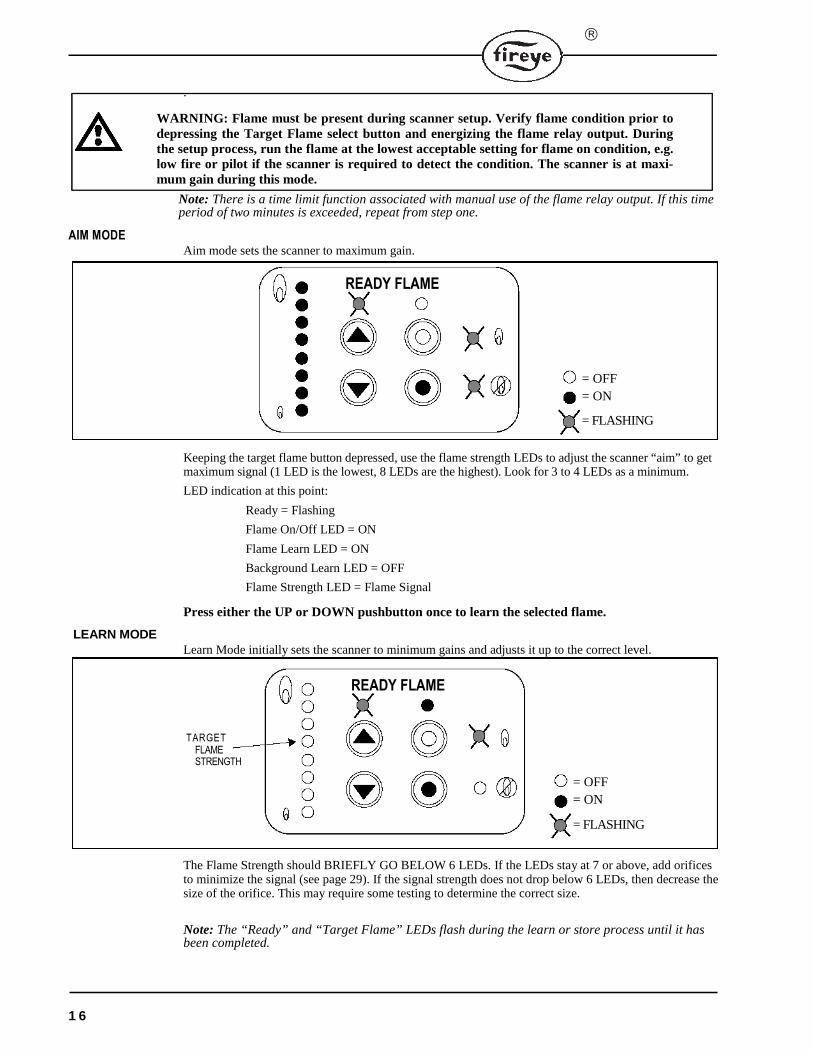
AIM MODEAim mode sets the scanner to maximum gain.
Keeping the target flame button depressed, use the flame strength LEDs to adjust the scanner “aim” to get maximum signal (1 LED is the lowest, 8 LEDs are the highest). Look for 3 to 4 LEDs as a minimum.
LED indication at this point:
Ready = Flashing
Flame On/Off LED = ON
Flame Learn LED = ON
Background Learn LED = OFF
Flame Strength LED = Flame Signal
Press either the UP or DOWN pushbutton once to learn the selected flame.
LEARN MODE Learn Mode initially sets the scanner to minimum gains and adjusts it up to the correct level.
The Flame Strength should BRIEFLY GO BELOW 6 LEDs. If the LEDs stay at 7 or above, add orifices to minimize the signal (see page 29). If the signal strength does not drop below 6 LEDs, then decrease the size of the orifice. This may require some testing to determine the correct size.
Note: The “Ready” and “Target Flame” LEDs flash during the learn or store process until it has been completed.
1 6

®
LEARNING THE TARGET FLAME
Ensure that the scanner is operating correctly prior to commissioning.
Note: Step 1 and Step 2 must be completed as a minimum to operate the scanner. Once Step 2 “Learn/Store the Target Flame” is completed the scanner will automatically set all flame switching thresholds. This would apply to a single flame application. Optionally Step 3 “Learn/Store the Background Flame” can be used to adjust the off switching threshold to discriminate a background flame condition. Refer to Step 3.
FIGURE 9. Examples of Flame Detection Thresholds (Learning Target Flame Only)
Step 3 – Learn/ Store the Background Flame (optional, see note above)
Note: Use Step 1 instructions on page 15 to enter the pass code before Step 3 can be carried out.
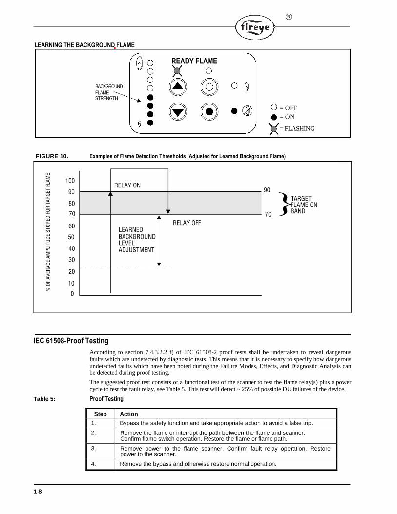
Press the background flame select button (the Learn Background Flame LED illuminates) to learn the selected background.
LED indication at this point:
Ready = Flashing
Flame On/Off LED = OFF
Flame Learn LED = OFF
Background Learn LED = ON
Note: The “Ready” LED flashes and the “Background Flame” LED is on steady during the learn process until it has been completed.
17
FLAME STRENGTH
BACKGROUND
READY FLAME
= OFF
= ON
= FLASHING
IEC 61508-Proof Testing
According to section 7.4.3.2.2 f) of IEC 61508-2 proof tests shall be undertaken to reveal dangerous faults which are undetected by diagnostic tests. This means that it is necessary to specify how dangerous undetected faults which have been noted during the Failure Modes, Effects, and Diagnostic Analysis can be detected during proof testing.
The suggested proof test consists of a functional test of the scanner to test the flame relay(s) plus a power cycle to test the fault relay, see Table 5. This test will detect ~ 25% of possible DU failures of the device.
Table 5: Proof Testing
Step Action
1. Bypass the safety function and take appropriate action to avoid a false trip.
2. Remove the flame or interrupt the path between the flame and scanner. Confirm flame switch operation. Restore the flame or flame path.
3. Remove power to the flame scanner. Confirm fault relay operation. Restore power to the scanner.
4. Remove the bypass and otherwise restore normal operation.
1 8
LEARNING THE BACKGROUND FLAMEdone
FIGURE 10. Examples of Flame Detection Thresholds (Adjusted for Learned Background Flame)
®
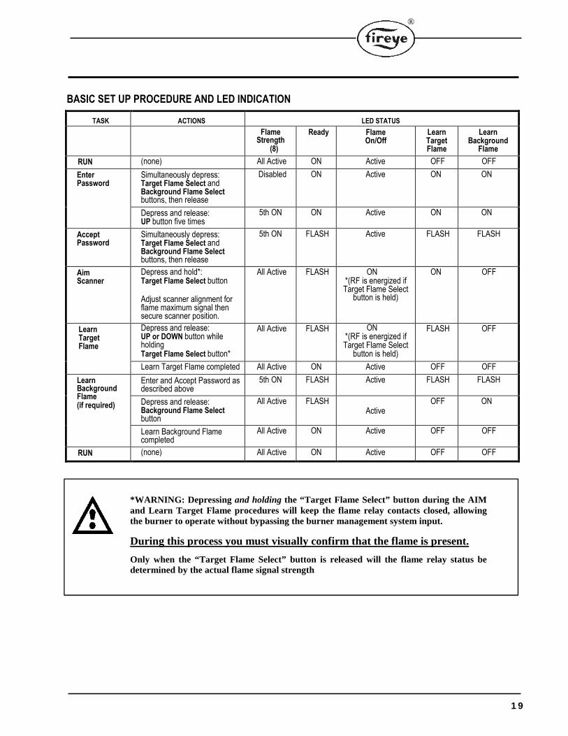
BASIC SET UP PROCEDURE AND LED INDICATION
TASK ACTIONS LED STATUS
Flame Strength
(8)
Ready Flame On/Off
Learn Target Flame
Learn Background
Flame
RUN (none) All Active ON Active OFF OFF
Enter Password
Simultaneously depress: Target Flame Select and Background Flame Select buttons, then release
Disabled ON Active ON ON
Depress and release: UP button five times
5th ON ON Active ON ON
Accept Password
Simultaneously depress: Target Flame Select and Background Flame Select buttons, then release
5th ON FLASH Active FLASH FLASH
Aim Scanner
Depress and hold*:Target Flame Select button
Adjust scanner alignment for flame maximum signal then secure scanner position.
All Active FLASH ON*(RF is energized if Target Flame Select
button is held)
ON OFF
Learn Target Flame
Depress and release:UP or DOWN button whileholding Target Flame Select button*
All Active FLASH ON*(RF is energized if Target Flame Select
button is held)
FLASH OFF
Learn Target Flame completed All Active ON Active OFF OFF
Learn Background Flame (if required)
Enter and Accept Password as described above
5th ON FLASH Active FLASH FLASH
Depress and release: Background Flame Select button
All Active FLASH Active
OFF ON
Learn Background Flame completed
All Active ON Active OFF OFF
RUN (none) All Active ON Active OFF OFF
*WARNING: Depressing and holding the “Target Flame Select” button during the AIM and Learn Target Flame procedures will keep the flame relay contacts closed, allowing the burner to operate without bypassing the burner management system input.
During this process you must visually confirm that the flame is present.
Only when the “Target Flame Select” button is released will the flame relay status be determined by the actual flame signal strength
1 9
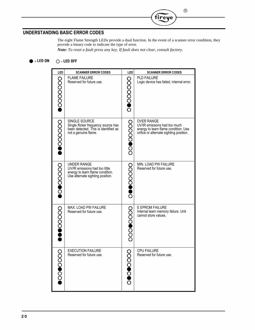
= LED ON = LED OFF
UNDERSTANDING BASIC ERROR CODES
The eight Flame Strength LEDs provide a dual function. In the event of a scanner error condition, they provide a binary code to indicate the type of error.
Note: To reset a fault press any key. If fault does not clear, consult factory.
LED SCANNER ERROR CODES LED SCANNER ERROR CODES
FLAME FAILURE Reserved for future use.
PLD FAILURE Logic device has failed, internal error.
SINGLE SOURCE Single flicker frequency source has been detected. This is identified as not a genuine flame.
OVER RANGE UV/IR emissions had too much energy to learn flame condition. Use orifice or alternate sighting position.
UNDER RANGE UV/IR emissions had too little energy to learn flame condition. Use alternate sighting position.
MIN. LOAD PW FAILURE Reserved for future use.
MAX. LOAD PW FAILURE Reserved for future use.
E EPROM FAILURE Internal learn memory failure. Unit cannot store values.
EXECUTION FAILURE Reserved for future use.
CPU FAILURE Reserved for future use.
2 0
®
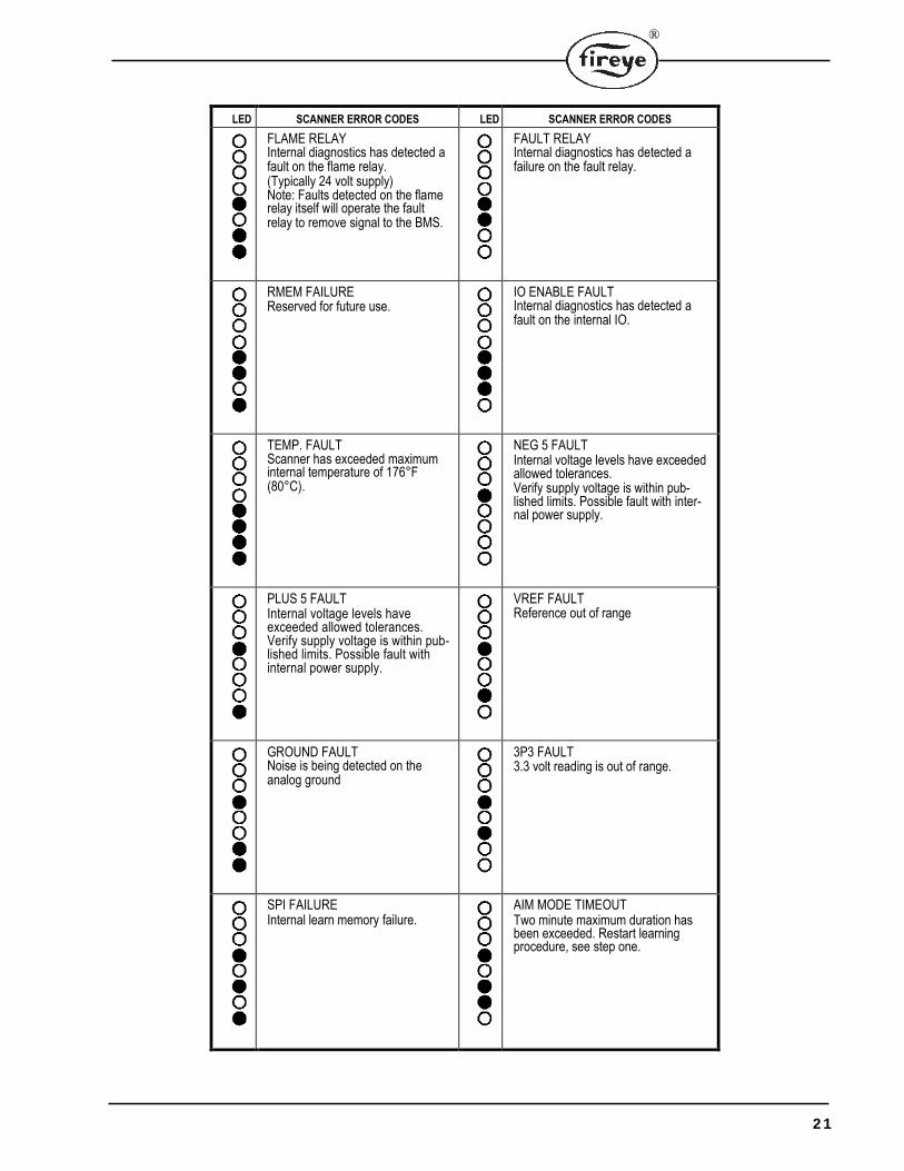
LED SCANNER ERROR CODES LED SCANNER ERROR CODES
FLAME RELAY Internal diagnostics has detected a fault on the flame relay. (Typically 24 volt supply) Note: Faults detected on the flame relay itself will operate the fault relay to remove signal to the BMS.
FAULT RELAY Internal diagnostics has detected a failure on the fault relay.
RMEM FAILURE Reserved for future use.
IO ENABLE FAULT Internal diagnostics has detected a fault on the internal IO.
TEMP. FAULT Scanner has exceeded maximum internal temperature of 176°F (80°C).
NEG 5 FAULT Internal voltage levels have exceeded allowed tolerances. Verify supply voltage is within pub-lished limits. Possible fault with inter-nal power supply.
PLUS 5 FAULT Internal voltage levels have exceeded allowed tolerances. Verify supply voltage is within pub-lished limits. Possible fault with internal power supply.
VREF FAULT Reference out of range
GROUND FAULT Noise is being detected on the analog ground
3P3 FAULT 3.3 volt reading is out of range.
SPI FAILURE Internal learn memory failure.
AIM MODE TIMEOUT Two minute maximum duration has been exceeded. Restart learning procedure, see step one.
2 1
READY FLAME
= OFF
= ON
= FLASHING
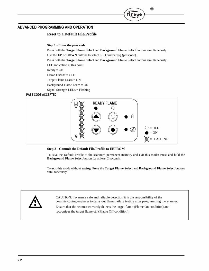
ADVANCED PROGRAMMING AND OPERATION
Reset to a Default File/Profile
Step 1 - Enter the pass code
Press both the Target Flame Select and Background Flame Select buttons simultaneously.
Use the UP or DOWN buttons to select LED number [6] (passcode).
Press both the Target Flame Select and Background Flame Select buttons simultaneously.
LED indication at this point:
Ready = ON
Flame On/Off = OFF
Target Flame Learn = ON
Background Flame Learn = ON
Signal Strength LEDs = Flashing
PASS CODE ACCEPTED
Step 2 - Commit the Default File/Profile to EEPROM
To save the Default Profile to the scanner's permanent memory and exit this mode: Press and hold the Background Flame Select button for at least 2 seconds.
To exit this mode without saving: Press the Target Flame Select and Background Flame Select buttons simultaneously.
CAUTION: To ensure safe and reliable detection it is the responsibility of the commissioning engineer to carry out flame failure testing after programming the scanner.
Ensure that the scanner correctly detects the target flame (Flame On condition) and
recognizes the target flame off (Flame Off condition).
2 2
®
Advanced Trip Diagnosis
The Phoenix scanner provides trip diagnosis for several advanced parameters including: Power Spec-trum Density, Average Amplitude, Best Fit, Single Source, Internal Fault, or a combination of these.
Whenever the scanner trips in response to a flame out condition, the reason for the trip is stored in a Trip Register. A total of eight (8) trip events are stored in the Trip Register with the oldest stored in the bottom position LED (1) and the newest in the top position LED (8).
NOTE: Once filled, the Trip Register MUST be reset in order to store subsequent trips. It will NOT automatically reset or roll-over.
Step 1 - Enter the pass code
Press both the Target Flame Select and Background Flame Select buttons simultaneously.
Use the UP or DOWN buttons to select LED number [2] (passcode).
Press both the Target Flame Select and Background Flame Select buttons simultaneously.
Step 2 - Selecting the Trip Event in the Trip Register
The contents of the Trip Register show the reason for a scanner trip and will be displayed using the
LEDs. To select a specific trip event in the Trip Register, use the UP button to scroll to the top of
the Trip Register and the DOWN button to scroll to the bottom of the Trip Register. Neither button
will roll over.
The oldest trip event is stored in the bottom LED position (LED = 1) and the newest trip event is
stored in the topmost LED position (2 through 8 depending on how many events are logged). Only
eight (8) trip events can be stored. They will not automatically reset or roll-over.
2 3
= LED ON = LED OFF
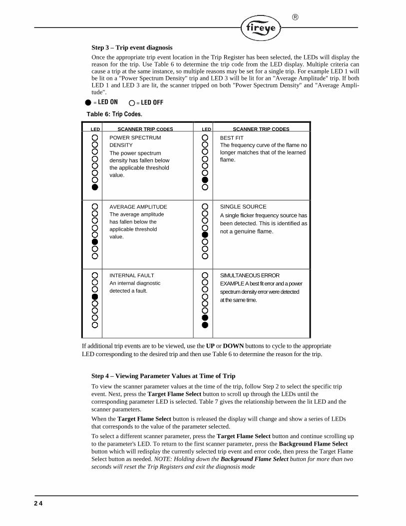
Step 3 – Trip event diagnosis
Once the appropriate trip event location in the Trip Register has been selected, the LEDs will display the reason for the trip. Use Table 6 to determine the trip code from the LED display. Multiple criteria can cause a trip at the same instance, so multiple reasons may be set for a single trip. For example LED 1 will be lit on a "Power Spectrum Density" trip and LED 3 will be lit for an "Average Amplitude" trip. If both LED 1 and LED 3 are lit, the scanner tripped on both "Power Spectrum Density" and "Average Ampli-tude".
Table 6: Trip Codes.
LED SCANNER TRIP CODES LED SCANNER TRIP CODES
POWER SPECTRUM
DENSITY
The power spectrum
density has fallen below
the applicable threshold
value.
BEST FIT
The frequency curve of the flame no
longer matches that of the learned
flame.
AVERAGE AMPLITUDE
The average amplitude
has fallen below the
applicable threshold
value.
SINGLE SOURCE
A single flicker frequency source has
been detected. This is identified as
not a genuine flame.
INTERNAL FAULT
An internal diagnostic
detected a fault.
SIMULTANEOUS ERROR
EXAMPLE A best fit error and a power
spectrum density error were detected
at the same time.
If additional trip events are to be viewed, use the UP or DOWN buttons to cycle to the appropriate LED corresponding to the desired trip and then use Table 6 to determine the reason for the trip.
Step 4 – Viewing Parameter Values at Time of Trip
To view the scanner parameter values at the time of the trip, follow Step 2 to select the specific trip event. Next, press the Target Flame Select button to scroll up through the LEDs until the corresponding parameter LED is selected. Table 7 gives the relationship between the lit LED and the scanner parameters.
When the Target Flame Select button is released the display will change and show a series of LEDs that corresponds to the value of the parameter selected.
To select a different scanner parameter, press the Target Flame Select button and continue scrolling up to the parameter's LED. To return to the first scanner parameter, press the Background Flame Select button which will redisplay the currently selected trip event and error code, then press the Target Flame Select button as needed. NOTE: Holding down the Background Flame Select button for more than two seconds will reset the Trip Registers and exit the diagnosis mode
2 4
®
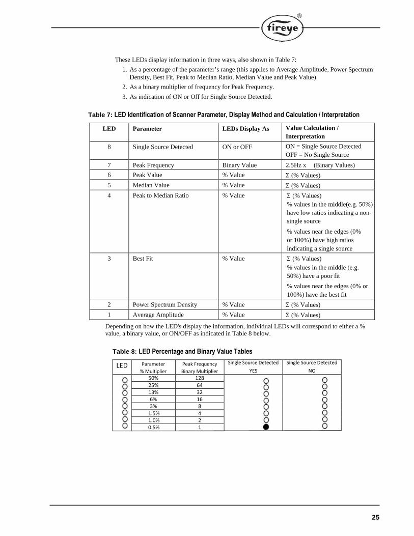
These LEDs display information in three ways, also shown in Table 7:
1. As a percentage of the parameter’s range (this applies to Average Amplitude, Power Spectrum Density, Best Fit, Peak to Median Ratio, Median Value and Peak Value)
2. As a binary multiplier of frequency for Peak Frequency.
3. As indication of ON or Off for Single Source Detected.
Table 7: LED Identification of Scanner Parameter, Display Method and Calculation / Interpretation
LED Parameter LEDs Display As Value Calculation /
Interpretation
8 Single Source Detected ON or OFF ON = Single Source Detected
OFF = No Single Source
7 Peak Frequency Binary Value 2.5Hz x (Binary Values)
6 Peak Value % Value Σ (% Values)
5 Median Value % Value Σ (% Values)
4 Peak to Median Ratio % Value Σ (% Values)
% values in the middle(e.g. 50%)
have low ratios indicating a non-
single source
% values near the edges (0%
or 100%) have high ratios
indicating a single source
3 Best Fit % Value Σ (% Values)
% values in the middle (e.g.
50%) have a poor fit
% values near the edges (0% or
100%) have the best fit
2 Power Spectrum Density % Value Σ (% Values)
1 Average Amplitude % Value Σ (% Values)
Depending on how the LED's display the information, individual LEDs will correspond to either a % value, a binary value, or ON/OFF as indicated in Table 8 below.
Table 8: LED Percentage and Binary Value Tables
LED Parameter
% Multiplier
Peak Frequency
Binary Multiplier
Single Source Detected
YES
Single Source Detected
NO
50% 128
25% 6413% 326% 163% 8
1.5% 41.0% 20.5% 1
25
How to Calculate a Parameter's Value using % Values:
The method sums the percentage associated with each LED to determine parameter's value.
1. View the LED display to determine which LEDs are lit.
2. Using Table 8, for each lit LED take the corresponding percentage (Parameter % Multiplier) and add them together.
How to Calculate Peak Frequency using the Binary Value:
The method sums binary values associated with each LED and then multiplies this sum by 2.5Hz to calculate peak frequency.
1. View the LED display to determine which LEDs are lit.
2. Using Table 8, for each lit LED take the corresponding binary value (Peak Frequency Binary Value) and add them together.
3. Multiply this sum times 2.5Hz for the Peak Frequency.
Determining Single Source:
Single Source Detected determination is simple. If no LED is lit, a single source has not been detected. If LED 1 is lit, a single source has been detected. The two LED configurations are shown in Table 8.
Step 5 - Resetting the Trip Register and Exiting the Trip Diagnosis Mode
To reset the Trip Register and exit this mode, hold the Background Flame Select button for at least 2 seconds.
To exit this mode without resetting the Trip Register press both the Target Flame Select and Back-ground Flame Select buttons.
NOTE: Once filled, the Trip Register MUST be reset in order to store subsequent trips. It will NOT auto-matically reset or roll-over.
2 6
®
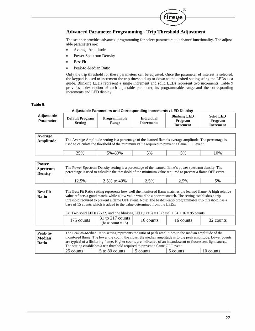
Advanced Parameter Programming - Trip Threshold Adjustment
The scanner provides advanced programming for select parameters to enhance functionality. The adjust-able parameters are:
• Average Amplitude
• Power Spectrum Density
• Best Fit
• Peak-to-Median Ratio
Only the trip threshold for these parameters can be adjusted. Once the parameter of interest is selected, the keypad is used to increment the trip threshold up or down to the desired setting using the LEDs as a guide. Blinking LEDs represent a single increment and solid LEDs represent two increments. Table 9 provides a description of each adjustable parameter, its programmable range and the corresponding increments and LED display.
Table 9:
Adjustable Parameters and Corresponding Increments / LED Display
Adjustable
Parameter Default Program
Setting Programmable
Range Individual Increments
Blinking LED Program
Increment
Solid LED Program
Increment
Average Amplitude The Average Amplitude setting is a percentage of the learned flame’s average amplitude. The percentage is
used to calculate the threshold of the minimum value required to prevent a flame OFF event.
25% 5%-80% 5% 5% 10%
Power Spectrum Density
The Power Spectrum Density setting is a percentage of the learned flame’s power spectrum density. The percentage is used to calculate the threshold of the minimum value required to prevent a flame OFF event.
12.5% 2.5% to 40% 2.5% 2.5% 5%
Best Fit Ratio
The Best Fit Ratio setting represents how well the monitored flame matches the learned flame. A high relative value reflects a good match, while a low value would be a poor mismatch. The setting establishes a trip threshold required to prevent a flame OFF event. Note: The best-fit-ratio programmable trip threshold has a base of 15 counts which is added to the value determined from the LEDs.
Ex. Two solid LEDs (2x32) and one blinking LED (1x16) = 15 (base) + 64 + 16 = 95 counts.
175 counts 31 to 217 counts (base count = 15)
16 counts 16 counts 32 counts
Peak-to- Median Ratio
The Peak-to-Median Ratio setting represents the ratio of peak amplitudes to the median amplitude of the monitored flame. The lower the count, the closer the median amplitude is to the peak amplitude. Lower counts are typical of a flickering flame. Higher counts are indicative of an incandescent or fluorescent light source. The setting establishes a trip threshold required to prevent a flame OFF event.
25 counts 5 to 80 counts 5 counts 5 counts 10 counts
27
Step 1 - Enter the Passcode
Press both the Target Flame Select and Background Flame Select buttons simultaneously.
Use the UP or DOWN buttons to select LED number [4] (passcode).
Press both the Target Flame Select and Background Flame Select buttons simultaneously.
Step 2 - Parameter Selection
The user selects which of the four parameters to program using the UP and DOWN buttons. A single LED will be lit (LED 1 to 4, bottom to top) to identify which parameter is selected, as follows. Once the appropriate LED is selected, press the Target Flame Select button to enter the program mode for the corresponding parameter.
LED Parameter8 Not used7 Not used6 Not used5 Not used4 Peak-to-Median Ratio3 Best Fit2 Power Spectrum Density1 Average Amplitude
Step 3 - Programming Parameter Trip Threshold
After pressing the Target Flame Select button in Step 2, the current parameter setting will be displayed. The user may increase or decrease the setting by pressing the UP or DOWN buttons (Reference Table 9 for parameter increments and corresponding LED displays).
Once the desired setting is entered, press the Background Flame Select button to save the setting in temporary memory and exit back to the parameter select menu.
If programming additional parameters is desired, continue to the next parameter using the UP or DOWN buttons and program the parameter as previously discussed.
Step 4 - Saving or Discarding Parameter Settings
To SAVE the modified parameters to permanent memory and EXIT this mode, press and hold the Back-ground Flame Select button for at least 2 seconds.
NOTE: Changes to the parameters will NOT be stored unless valid flame data is already present in the scanner's permanent memory. Either a flame must have been previously learned or the Default Profile must have been loaded.
To DISCARD any changes to these parameters, press the Background Flame Select and Target Flame Select buttons simultaneously. This will discard all parameter changes while remaining in the program mode.
To DISCARD any changes and EXIT the mode, press and hold the Background Flame Select and Tar-get Flame Select buttons down for at least 2 seconds.
CAUTION: To ensure safe and reliable detection it is the responsibility of the commissioning engineer to carry out flame failure testing after programming the scanner.
Ensure that the scanner correctly detects the target flame (Flame On condition) and
recognizes the target flame off (Flame Off condition).
2 8
®
®
FIELD OF VIEW
F I E L D O F
V I E W
SWIVEL MOUNT
1” SWIVEL MOUNT
BALL
ORIFICE ORIFICERETAINER
ALTERNATE PURGE AIR SUPPLY
60-1199-1,2 SEALING COUPLING with Quartz Window
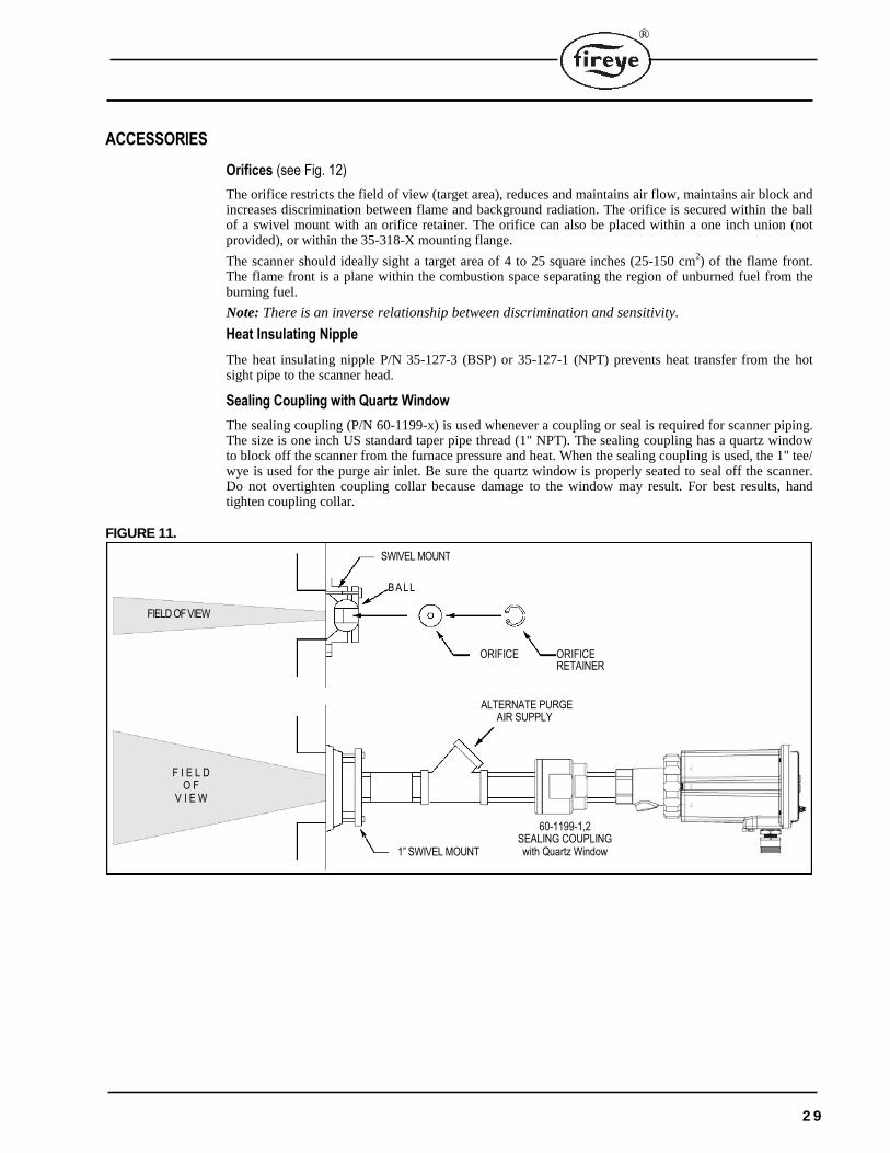
ACCESSORIES
Orifices (see Fig. 12)
The orifice restricts the field of view (target area), reduces and maintains air flow, maintains air block and increases discrimination between flame and background radiation. The orifice is secured within the ball of a swivel mount with an orifice retainer. The orifice can also be placed within a one inch union (not provided), or within the 35-318-X mounting flange.
The scanner should ideally sight a target area of 4 to 25 square inches (25-150 cm2) of the flame front. The flame front is a plane within the combustion space separating the region of unburned fuel from the burning fuel.
Note: There is an inverse relationship between discrimination and sensitivity.
Heat Insulating Nipple
The heat insulating nipple P/N 35-127-3 (BSP) or 35-127-1 (NPT) prevents heat transfer from the hot sight pipe to the scanner head.
Sealing Coupling with Quartz Window
The sealing coupling (P/N 60-1199-x) is used whenever a coupling or seal is required for scanner piping. The size is one inch US standard taper pipe thread (1" NPT). The sealing coupling has a quartz window to block off the scanner from the furnace pressure and heat. When the sealing coupling is used, the 1" tee/ wye is used for the purge air inlet. Be sure the quartz window is properly seated to seal off the scanner. Do not overtighten coupling collar because damage to the window may result. For best results, hand tighten coupling collar.
FIGURE 11.
2 9
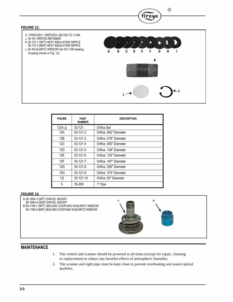
A. THROUGH I. ORIFICES .062 DIA TO .5 DIAJ. 34-181 ORIFICE RETAINER K.35-127-1 (NPT) HEAT INSULATING NIPPLE
35-127-3 (BSP) HEAT INSULATING NIPPLE L. 92-48 QUARTZ WINDOW (for 60-1199 Sealing
Coupling shown in Fig. 13).
A.60-1664-3 (NPT) SWIVEL MOUNT 60-1664-4 (BSP) SWIVEL MOUNT
B.60-1199-1 (NPT) SEALING COUPLING W/QUARTZ WINDOW 60-1199-2 (BSP) SEALING COUPLING W/QUARTZ WINDOW
A B
MAINTENANCE
1. The control and scanner should be powered at all times (except for repair, cleaning or replacement) to reduce any harmful effects of atmospheric humidity.
2. The scanner and sight pipe must be kept clean to prevent overheating and assure optical qualities.
3 0
FIGURE 12.
FIGURE PART NUMBER
DESCRIPTION
12(A-J) 53-121 Orifice Set
12A 53-121-2 Orifice .062" Diameter
12B 53-121-3 Orifice .078" Diameter
12C 53-121-4 Orifice .093" Diameter
12D 53-121-5 Orifice .109" Diameter
12E 53-121-6 Orifice .125" Diameter
12F 53-121-7 Orifice .187" Diameter
12G 53-121-8 Orifice .250" Diameter
12H 53-121-9 Orifice .375" Diameter
12I 53-121-10 Orifice .50" Diameter
5 35-200 1" Wye
FIGURE 13.
®
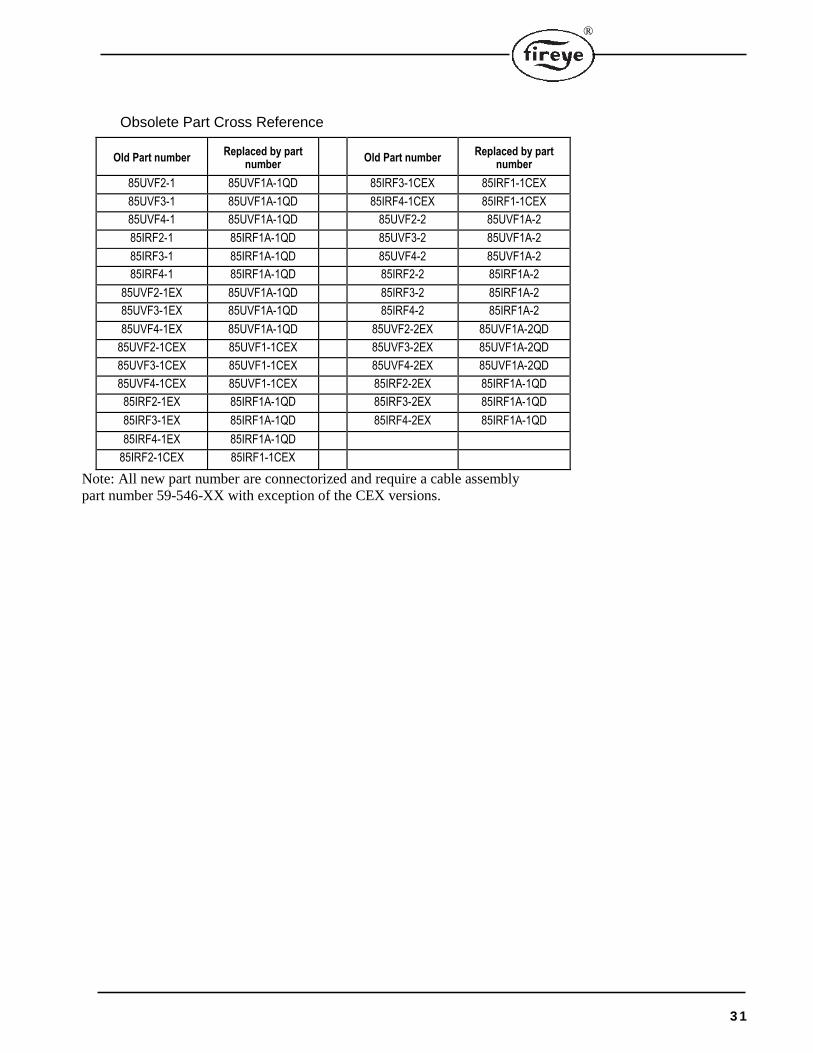
Obsolete Part Cross Reference
Old Part number Replaced by part
number Old Part number
Replaced by part number
85UVF2-1 85UVF1A-1QD 85IRF3-1CEX 85IRF1-1CEX
85UVF3-1 85UVF1A-1QD 85IRF4-1CEX 85IRF1-1CEX
85UVF4-1 85UVF1A-1QD 85UVF2-2 85UVF1A-2
85IRF2-1 85IRF1A-1QD 85UVF3-2 85UVF1A-2
85IRF3-1 85IRF1A-1QD 85UVF4-2 85UVF1A-2
85IRF4-1 85IRF1A-1QD 85IRF2-2 85IRF1A-2
85UVF2-1EX 85UVF1A-1QD 85IRF3-2 85IRF1A-2
85UVF3-1EX 85UVF1A-1QD 85IRF4-2 85IRF1A-2
85UVF4-1EX 85UVF1A-1QD 85UVF2-2EX 85UVF1A-2QD
85UVF2-1CEX 85UVF1-1CEX 85UVF3-2EX 85UVF1A-2QD
85UVF3-1CEX 85UVF1-1CEX 85UVF4-2EX 85UVF1A-2QD
85UVF4-1CEX 85UVF1-1CEX 85IRF2-2EX 85IRF1A-1QD
85IRF2-1EX 85IRF1A-1QD 85IRF3-2EX 85IRF1A-1QD
85IRF3-1EX 85IRF1A-1QD 85IRF4-2EX 85IRF1A-1QD
85IRF4-1EX 85IRF1A-1QD
85IRF2-1CEX 85IRF1-1CEX
Note: All new part number are connectorized and require a cable assembly part number 59-546-XX with exception of the CEX versions.
3 1
®
NOTICEWhen Fireye products are combined with equipment manufactured by others and/or integrated into sys-tems designed or manufactured by others, the Fireye warranty, as stated it its General Terms and Condi-tions of Sale, pertains only to the Fireye products and not to any other equipment or to the combined system or its overall performance.
WARRANTIESFIREYE guarantees for one year from the date of installation or 18 months from date of manufacture of its products to replace, or, at its option, to repair any product or part thereof (except lamps and photo-cells) which is found defective in material or workmanship or which otherwise fails to conform to the description of the product on the face of its sales order. THE FOREGOING IS IN LIEU OF ALL OTHER WARRANTIES AND FIREYE MAKES NO WARRANTY OF MERCHANTABILITY OR ANY OTHER WARRANTY, EXPRESS OR IMPLIED. Except as specifically stated in these general terms and conditions of sale, remedies with respect to any product or part number manufactured or sold by Fireye shall be limited exclusively to the right to replacement or repair as above provided. In no event shall Fireye be liable for consequential or special damages of any nature that may arise in con-nection with such product or part.
FIREYE® CU-119 3 Manchester Road July 10, 2018 Derry, New Hampshire 03038 USA www.fireye.com
3 2