Embed Size (px)
Citation preview
www.belman.com
weighing technology. Its very low inherent resistance makes it very suitable for decoupling scales / load cells
Bellow designHigh-corrugated rubber bellow with reinforcement and shaped sealing bead with core ring, self-sealing (no additional seals required). Suitable for swiveling flanges.
Vacuum resistanceCan be used up to -200 mbar without additional accessories, full vacuum possible with vacuum supporting spiral/ring.
Flange versionBoth sides with swiveling flange made of galvanized steel with threaded holes, drilled according to DIN PN 10 (standard). Other materials and dimensions are possible.
Approvals/ConformitySimilar to DIN 4809 / TÜV approved, drinking water and shipbuilding approval, FDA and EG 1935/2004 conform.
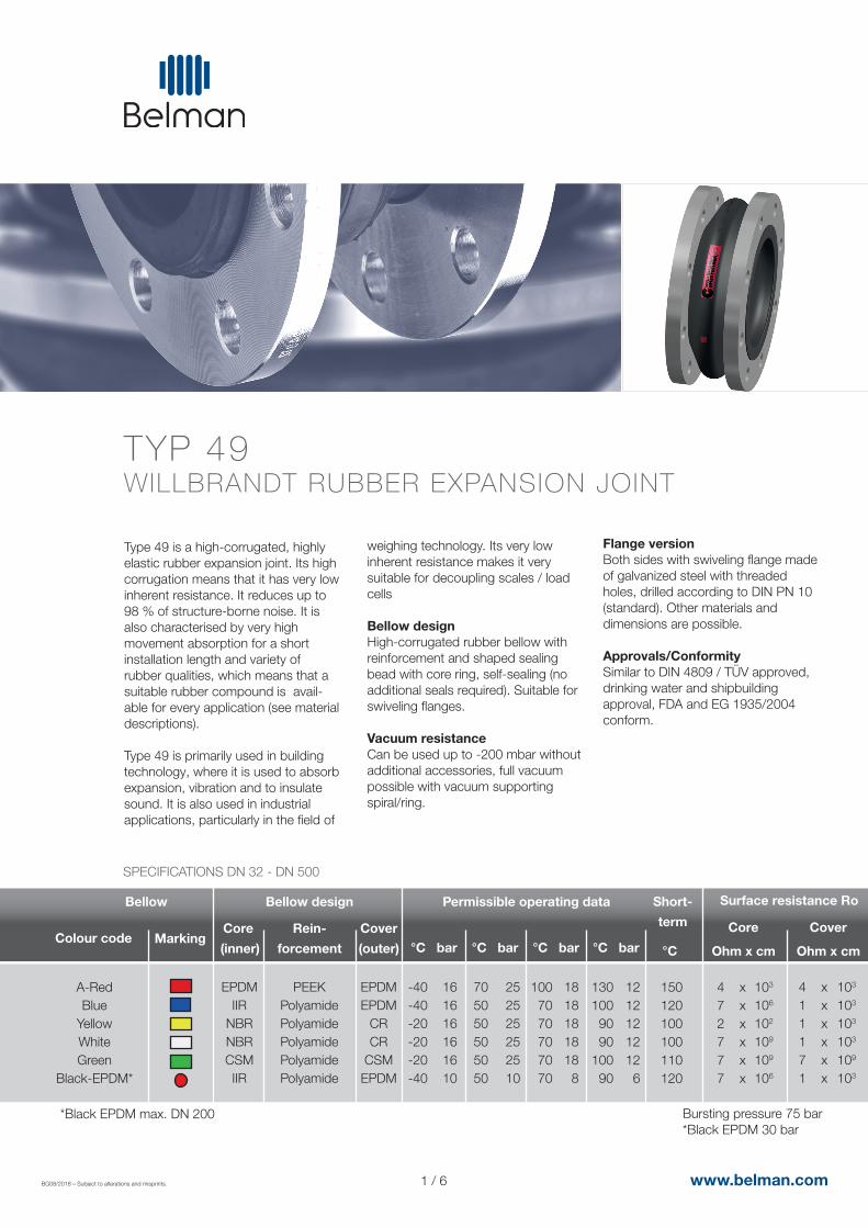
Type 49 is a high-corrugated, highly elastic rubber expansion joint. Its high corrugation means that it has very low inherent resistance. It reduces up to 98 % of structure-borne noise. It is also characterised by very high movement absorption for a short installation length and variety of rubber qualities, which means that a suitable rubber compound is avail-able for every application (see material descriptions).
Type 49 is primarily used in building technology, where it is used to absorb expansion, vibration and to insulate sound. It is also used in industrial applications, particularly in the field of
TYP 49 WILLBRANDT RUBBER EXPANSION JOINT
1 / 6
Colour code
EPDMIIR
NBRNBRCSMIIR
MarkingCore
(inner)
Rein-
forcement
Cover
(outer)
Short-
term
Surface resistance Ro
°C bar °C bar °C bar °C bar
A-RedBlue
YellowWhiteGreen
Black-EPDM*
PEEKPolyamidePolyamidePolyamidePolyamidePolyamide
EPDMEPDM
CRCR
CSMEPDM
-40-40-20-20-20-40
705050505050
1007070707070
1301009090
10090
12121212126
150120100100110120
472777
xxxx xx
103
106
102
109
109
106
18181818188
252525252510
161616161610
Bellow Bellow design Permissible operating data
SPECIFICATIONS DN 32 - DN 500
BG08/2018 – Subject to alterations and misprints.
Bursting pressure 75 bar*Black EPDM 30 bar
°C
Core Cover
Ohm x cm Ohm x cm
411171
xxxx xx
103
103
103
103
109
103
*Black EPDM max. DN 200
2 / 6
Important information For aggressive media, please see the resistance table (can be requested separately).
The bellows should not be painted or insulated. Please refer to the installation instructions.
We will be happy to send you further information on the individual types and designs.
solutions, weak acids and weakalkaline solutions. Not suitable for oil products or cooling water withadditives containing oil. Electrially dissipative inner surface andelectrically conductive outer surface.
Type 49 yellowFor oils, lubricants, fuels, gases, city and natural gas (not liquefied). Electrically conductive surface.
Type 49 whiteFor foodstuffs containing oil and fat (rubber in food-grade). Electrically insulating inner surface,
APPLICATION
Type 49 A-red For heating installations according to DIN 4809. For many years of opera-tion under constant loading with hot water and heating water at 100°C/ 110°C at 10 bar/6 bar operating pressure. Electrically conductive surface. Not suitable for media with additives containing oil.
Type 49 blueFor drinking water, hot water, sea water, cooling water with chemicaladditives for treating water, saline
electrically conductive outer surface. Not suitable for drinking water.
Type 49 greenFor chemicals, aggressive chemical wastewater and compressor air containing oil. Electrically insulating sufrace.
Type 49 black, EPDMFor hot and cold water, sea water, cooling water, weak acids and alkali solutions, technical alcohols, esters and ketones. Electrically dissipative inner surface, conductive outer surface. Max. pressure 10 bar.
BG08/2018 – Subject to alterations and misprints. www.belman.com
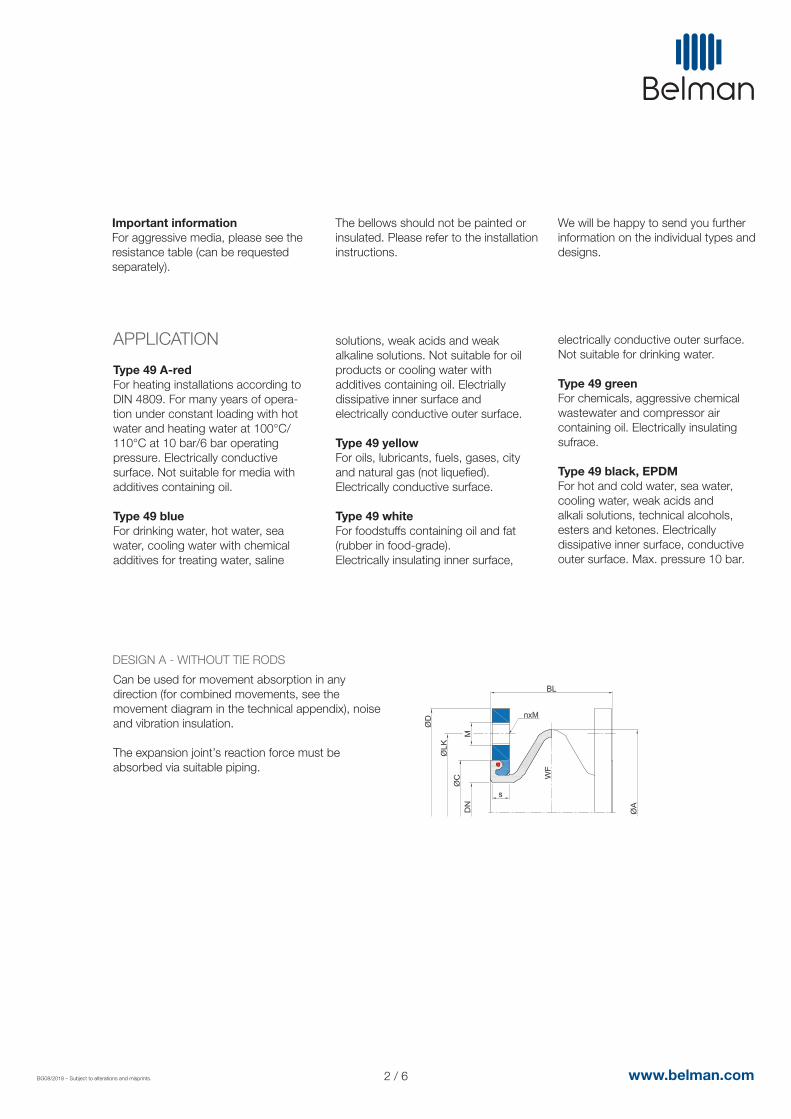
Can be used for movement absorption in any direction (for combined movements, see the movement diagram in the technical appendix), noise and vibration insulation.
The expansion joint’s reaction force must be absorbed via suitable piping.
DESIGN A - WITHOUT TIE RODS
Permissible degree of utilisation for movement areas:- up to 50 °C: Utilisation ~ 100 %- up to 70 °C: Utilisation ~ 75 %- up to 90 °C: Utilisation ~ 60 %
*1 WF = effective area *2 Other standards/dimensions possible.
3 / 6
DN WeightBL
mm
Flange PN 10*2 Movement absorption
AX LA
Bellow
ØA
mm
ØD
mm
ØLK
mm kg
M s
mm
+
mm
-
mm
+/-
mm
°
+/-
nWF*1
mm2
3240506580
100125150200250300350400500
100100100100100100100100100100100100110110
110110120135150170195260310360410460515615
18001800350056008700
130001900026300416006070083000
110000138500209100
140150165185200220250285340395445505565670
100110125145160180210240295350400460515620
M16M16M16M16M16M16M16M20M20M20M20M20M24M24
444888888
1212161620
1616161618181820202020202525
2020202020202020202020202020
3030303030303030303030303030
3030303030303030303030303030
77777777777777
3.03.64.45.36.57.38.9
12.316.220.323.130.143.253.8
BG08/2018 – Subject to alterations and misprints. www.belman.com
DIMENSIONS FOR DESIGN A
AN
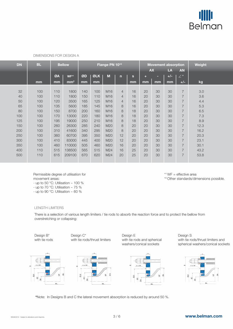
There is a selection of various length limiters / tie rods to absorb the reaction force and to protect the bellow from overstretching or collapsing:
Design B*with tie rods
Design C*with tie rods/thrust limiters
Design Ewith tie rods and spherical washers/conical sockets
Design Swith tie rods/thrust limiters and spherical washers/conical sockets
*Note: In Designs B and C the lateral movement absorption is reduced by around 50 %.
LENGTH LIMITERS
4 / 6BG08/2018 – Subject to alterations and misprints. www.belman.com
Accessories
l Vacuum supporting spirals/rings
l Guide sleeves
l Potential equalisation
l Flame-resistant protective covers
l Dust and splash protection covers
l Earth cover hoods
DN
Flange PN 10 (example dimensions)
S
mm
nBL
mm
3240506580
100125150200250300350400500
100100100100100100100100100100100100110110
1616161618181820202020202525
444888888
1212161620
B
mm
230240255275290310340375440509559619700810
ØD
mm
140150165185200220250285340395445505565670
ØPCD
mm
100110125145160180210240295350400460515620
M
M16M16M16M16M16M16M16M20M20M20M20M20M24M24
ØC
mm
797989
104119142169195245295345396450550
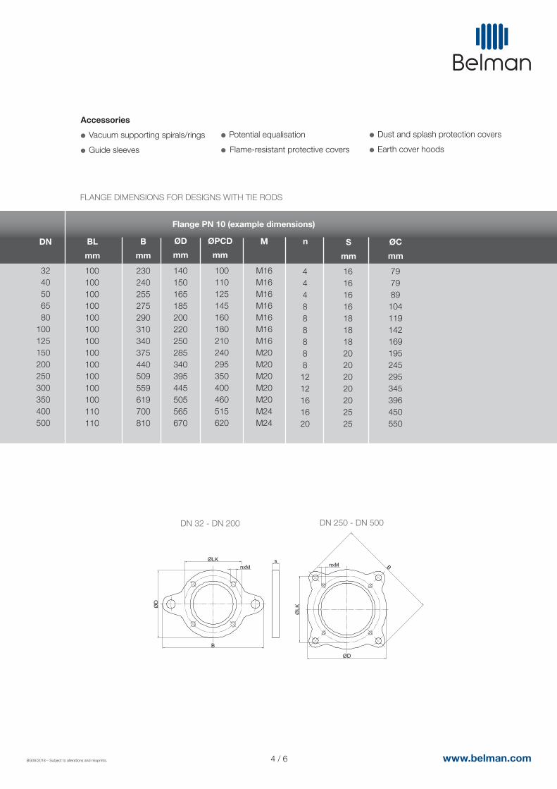
FLANGE DIMENSIONS FOR DESIGNS WITH TIE RODS
DN 32 - DN 200 DN 250 - DN 500
5 / 6BG08/2018 – Subject to alterations and misprints. www.belman.com
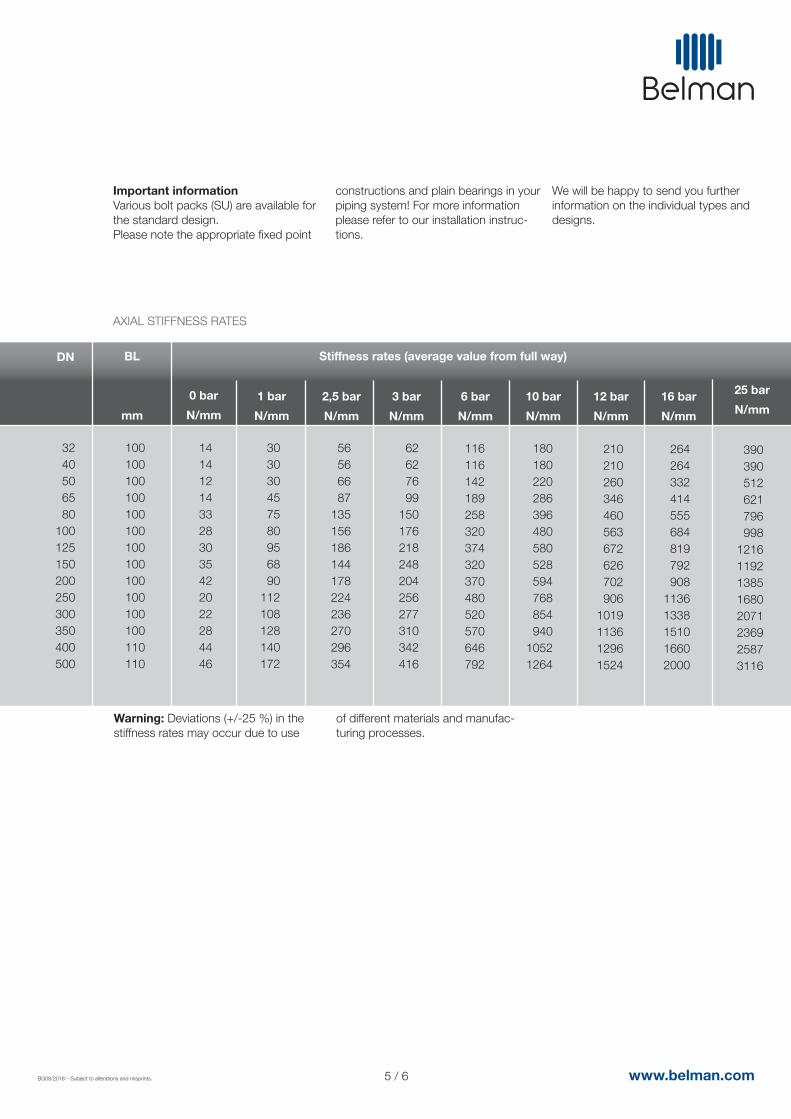
Important information Various bolt packs (SU) are available for the standard design.Please note the appropriate fixed point
constructions and plain bearings in yourpiping system! For more information please refer to our installation instruc-tions.
We will be happy to send you further information on the individual types and designs.
DN BL
mm
Stiffness rates (average value from full way)
0 bar
N/mm
3240506580
100125150200250300350400500
100100100100100100100100100100100100110110
1414121433283035422022284446
AXIAL STIFFNESS RATES
1 bar
N/mm
303030457580956890
112108128140172
2,5 bar
N/mm
56566687
135156186144178224236270296354
3 bar
N/mm
62627699
150176218248204256277310342416
6 bar
N/mm
116116142189258320374320370480520570646792
10 bar
N/mm
180180220286396480580528594768854940
10521264
12 bar
N/mm
210210260346460563672626702906
1019113612961524
16 bar
N/mm
264264332414555684819792908
11361338151016602000
25 bar
N/mm
390390512621796998
12161192138516802071236925873116
Warning: Deviations (+/-25 %) in the stiffness rates may occur due to use
of different materials and manufac-turing processes.
6 / 6BG08/2018 – Subject to alterations and misprints. www.belman.com
DN BL
mm
Stiffness rates (average value from full way)
0 bar
N/mm
3240506580
100125150200250300350400500
100100100100100100100100100100100100110110
1111172132384548
103126167137187203
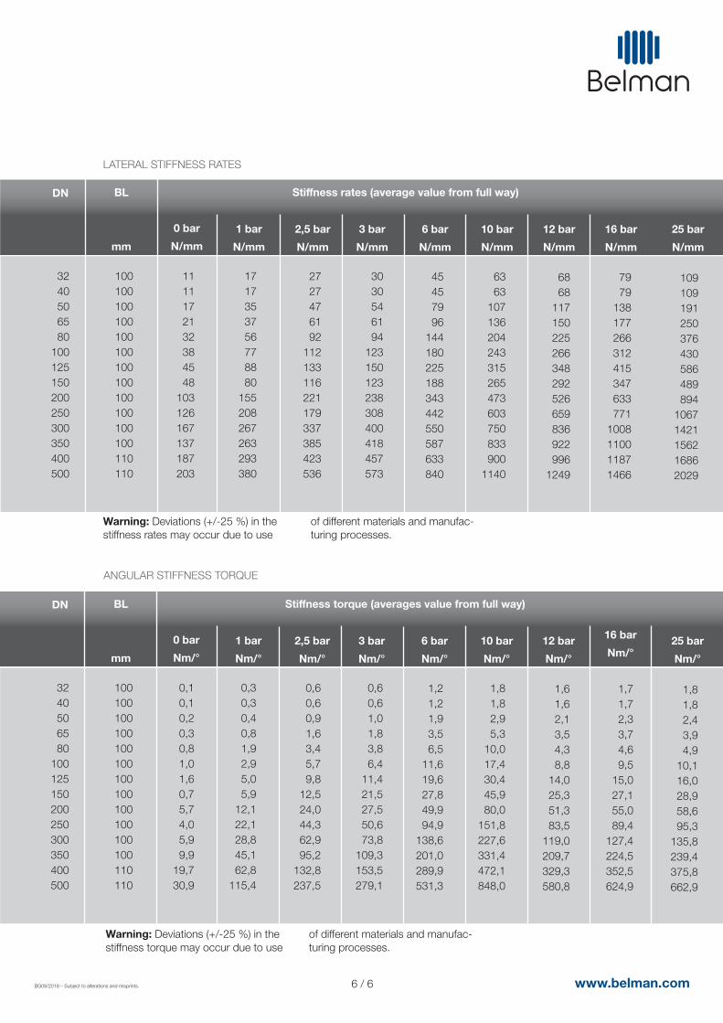
LATERAL STIFFNESS RATES
1 bar
N/mm
1717353756778880
155208267263293380
2,5 bar
N/mm
2727476192
112133116221179337385423536
3 bar
N/mm
3030546194
123150123238308400418457573
6 bar
N/mm
45457996
144180225188343442550587633840
10 bar
N/mm
6363
107136204243315265473603750833900
1140
12 bar
N/mm
6868
117150225266348292526659836922996
1249
16 bar
N/mm
7979
138177266312415347633771
1008110011871466
25 bar
N/mm
109109191250376430586489894
10671421156216862029
DN BL
mm
Stiffness torque (averages value from full way)
0 bar
Nm/°
3240506580
100125150200250300350400500
100100100100100100100100100100100100110110
0,10,10,20,30,81,01,60,75,74,05,99,9
19,730,9
ANGULAR STIFFNESS TORQUE
1 bar
Nm/°
0,30,30,40,81,92,95,05,9
12,122,128,845,162,8
115,4
2,5 bar
Nm/°
0,60,60,91,63,45,79,8
12,524,044,362,995,2
132,8237,5
3 bar
Nm/°
0,60,61,01,83,86,4
11,421,527,550,673,8
109,3153,5279,1
6 bar
Nm/°
1,21,21,93,56,5
11,619,627,849,994,9
138,6201,0289,9531,3
10 bar
Nm/°
1,81,82,95,3
10,017,430,445,980,0
151,8227,6331,4472,1848,0
12 bar
Nm/°
1,61,62,13,54,38,8
14,025,351,383,5
119,0209,7329,3580,8
16 bar
Nm/°
1,71,72,33,74,69,5
15,027,155,089,4
127,4224,5352,5624,9
25 bar
Nm/°
1,81,82,43,94,9
10,116,028,958,695,3
135,8239,4375,8662,9
Warning: Deviations (+/-25 %) in the stiffness rates may occur due to use
of different materials and manufac-turing processes.
Warning: Deviations (+/-25 %) in the stiffness torque may occur due to use
of different materials and manufac-turing processes.


![Typ / Type Drehmoment / Torque [Nm] A / Fdonar.messe.de › exhibitor › hannovermesse › 2018 › A... · In der Schlinge 6, 59227 Ahlen / Germany T: +49 (0) 2382-855 7010 F: +49](https://img.pdfslide.us/doc/110x75/5f031b717e708231d4079201/typ-type-drehmoment-torque-nm-a-a-exhibitor-a-hannovermesse-a-2018.jpg)