Embed Size (px)
Citation preview

����������
Two-Wire Toroidal Conductivity Transmitter
Instruction ManualPN 51-1181T/rev.CApril 2003
DANGERHAZARDOUS AREA INSTALLATION
INTRINSICALLY SAFE INSTALLATIONInstallations in hazardous area locations must becarefully evaluated by qualified on site safety per-sonnel. Transmitter and Sensor alone are notIntrinsically safe. To secure and maintain an intrin-sically safe installation, a certified safety barriermust be used and the installation must comply withthe governing approval agency (FM, CSA orBASEEFA/CENELEC) installation drawing require-ments (see Section 2.0 - Installation).
EXPLOSION-PROOF INSTALLATIONCaution: Sensors are not explosion-proof. If thesensor must be installed in a hazardous location anintrinsically safe system must be implemented.
To maintain the explosion-proof rating of the trans-mitter, the following conditions must be met:
• Discontinue power supply before removingenclosure covers.
• Transmitter covers must be properly installedduring power on operation.
• Explosion proof "Y" fittings must be properlyinstalled with sealing compound prior to apply-ing power to the transmitter.
• Serial tag cover over the external Zero andSpan adjustments must be in place.
• See Installation Section for details.
Proper installation, operation and servicing of thisinstrument in a Hazardous Area Installation isentirely the responsibility of the user.
ESSENTIAL INSTRUCTIONSREAD THIS PAGE BEFORE PROCEEDING!
Rosemount Analytical designs, manufactures, and tests its products to meetmany national and international standards. Because these instruments aresophisticated technical products, you must properly install, use, and main-tain them to ensure they continue to operate within their normal specifica-tions. The following instructions must be adhered to and integrated into yoursafety program when installing, using, and maintaining RosemountAnalytical products. Failure to follow the proper instructions may cause anyone of the following situations to occur: Loss of life; personal injury; propertydamage; damage to this instrument; and warranty invalidation.
• Read all instructions prior to installing, operating, and servicing the prod-uct. If this Instruction Manual is not the correct manual, telephone 1-800-654-7768 and the requested manual will be provided. Save thisInstruction Manual for future reference.
• If you do not understand any of the instructions, contact your Rosemountrepresentative for clarification.
• Follow all warnings, cautions, and instructions marked on and suppliedwith the product.
• Inform and educate your personnel in the proper installation, operation,and maintenance of the product.
• Install your equipment as specified in the Installation Instructions of theappropriate Instruction Manual and per applicable local and nationalcodes. Connect all products to the proper electrical and pressuresources.
• To ensure proper performance, use qualified personnel to install, operate,update, program, and maintain the product.
• When replacement parts are required, ensure that qualified people usereplacement parts specified by Rosemount. Unauthorized parts and pro-cedures can affect the product’s performance and place the safe opera-tion of your process at risk. Look alike substitutions may result in fire,electrical hazards, or improper operation.
• Ensure that all equipment doors are closed and protective covers are inplace, except when maintenance is being performed by qualified per-sons, to prevent electrical shock and personal injury.
Emerson Process Management
Liquid Division2400 Barranca ParkwayIrvine, CA 92606 USATel: (949) 757-8500Fax: (949) 474-7250
http://www.raihome.com
© Rosemount Analytical Inc. 2003
About This DocumentThis manual contains instructions for installation and operation of Model 1181T Two-wire ToroidalConductivity Transmitter. The following list provides notes concerning all revisions of this document.
Rev. Level Date Notes
0 5/00 The initial release of the product manual. The manual has been reformatted to reflect the Emerson documentation style and updated to reflect any changes in the product offering.
A 7/01 Added CE addendum info to page 6.
B 7/02 Updated drawing on page 7.
C 4/03 Updated CE cert reference on page 1.
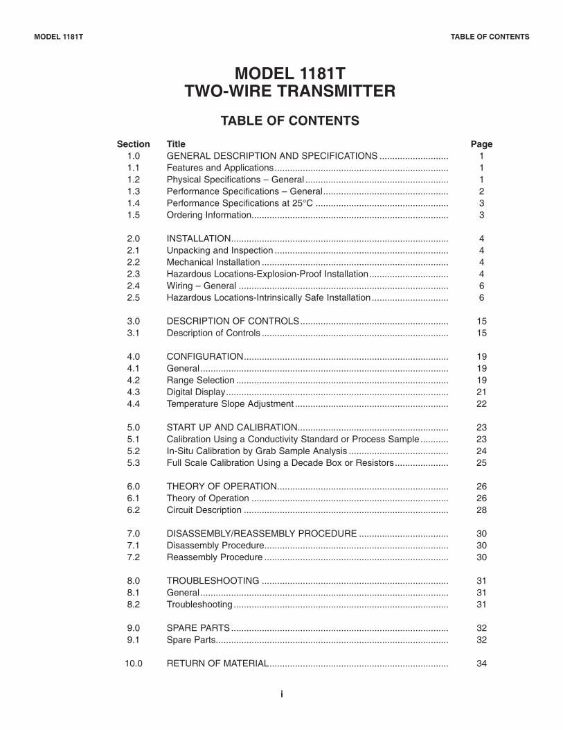
MODEL 1181TTWO-WIRE TRANSMITTER
TABLE OF CONTENTS
Section Title Page1.0 GENERAL DESCRIPTION AND SPECIFICATIONS ........................... 11.1 Features and Applications.................................................................... 11.2 Physical Specifications – General ........................................................ 11.3 Performance Specifications – General................................................. 21.4 Performance Specifications at 25°C .................................................... 31.5 Ordering Information............................................................................. 3
2.0 INSTALLATION..................................................................................... 42.1 Unpacking and Inspection .................................................................... 42.2 Mechanical Installation ......................................................................... 42.3 Hazardous Locations-Explosion-Proof Installation............................... 42.4 Wiring – General .................................................................................. 62.5 Hazardous Locations-Intrinsically Safe Installation.............................. 6
3.0 DESCRIPTION OF CONTROLS.......................................................... 153.1 Description of Controls ......................................................................... 15
4.0 CONFIGURATION................................................................................ 194.1 General................................................................................................. 194.2 Range Selection ................................................................................... 194.3 Digital Display....................................................................................... 214.4 Temperature Slope Adjustment ............................................................ 22
5.0 START UP AND CALIBRATION........................................................... 235.1 Calibration Using a Conductivity Standard or Process Sample........... 235.2 In-Situ Calibration by Grab Sample Analysis ....................................... 245.3 Full Scale Calibration Using a Decade Box or Resistors..................... 25
6.0 THEORY OF OPERATION................................................................... 266.1 Theory of Operation ............................................................................. 266.2 Circuit Description ................................................................................ 28
7.0 DISASSEMBLY/REASSEMBLY PROCEDURE ................................... 307.1 Disassembly Procedure........................................................................ 307.2 Reassembly Procedure ........................................................................ 30
8.0 TROUBLESHOOTING ......................................................................... 318.1 General................................................................................................. 318.2 Troubleshooting .................................................................................... 31
9.0 SPARE PARTS..................................................................................... 329.1 Spare Parts........................................................................................... 32
10.0 RETURN OF MATERIAL...................................................................... 34
i
MODEL 1181T TABLE OF CONTENTS
ii
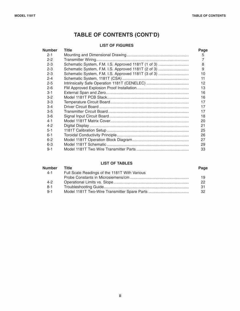
TABLE OF CONTENTS (CONT'D)
LIST OF FIGURESNumber Title Page
2-1 Mounting and Dimensional Drawing......................................................... 52-2 Transmitter Wiring..................................................................................... 72-3 Schematic System, F.M. I.S. Approved 1181T (1 of 3) ............................ 82-3 Schematic System, F.M. I.S. Approved 1181T (2 of 3) ............................ 92-3 Schematic System, F.M. I.S. Approved 1181T (3 of 3) ............................ 102-4 Schematic System, 1181T (CSA) ............................................................. 112-5 Intrinsically Safe Operation 1181T (CENELEC) ....................................... 122-6 FM Approved Explosion Proof Installation................................................ 133-1 External Span and Zero............................................................................ 163-2 Model 1181T PCB Stack........................................................................... 163-3 Temperature Circuit Board........................................................................ 173-4 Driver Circuit Board .................................................................................. 173-5 Transmitter Circuit Board.......................................................................... 173-6 Signal Input Circuit Board......................................................................... 184-1 Model 1181T Matrix Cover........................................................................ 204-2 Digital Display ........................................................................................... 215-1 1181T Calibration Setup ........................................................................... 256-1 Toroidal Conductivity Principle.................................................................. 266-2 Model 1181T Operation Block Diagram.................................................... 276-3 Model 1181T Schematic ........................................................................... 299-1 Model 1181T Two Wire Transmitter Parts ................................................ 33
LIST OF TABLESNumber Title Page
4-1 Full Scale Readings of the 1181T With VariousProbe Constants in Microsiemens/cm ...................................................... 19
4-2 Operational Limits vs. Slope..................................................................... 228-1 Troubleshooting Guide.............................................................................. 319-1 Model 1181T Two-Wire Transmitter Spare Parts ..................................... 32
MODEL 1181T TABLE OF CONTENTS
1
MODEL 1181T SECTION 1.0GENERAL DESCRIPTION AND SPECIFICATIONS
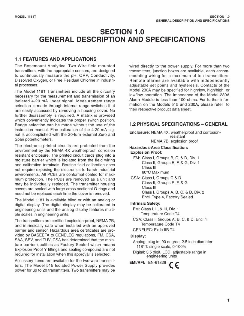
1.1 FEATURES AND APPLICATIONSThe Rosemount Analytical Two-Wire field mountedtransmitters, with the appropriate sensors, are designedto continuously measure the pH, ORP, Conductivity,Dissolved Oxygen, or Free Residual Chlorine in industri-al processes.
The Model 1181 Transmitters include all the circuitrynecessary for the measurement and transmission of anisolated 4-20 mA linear signal. Measurement rangeselection is made through internal range switches thatare easily accessed by removing a housing cover. Nofurther disassembly is required. A matrix is providedwhich conveniently indicates the proper switch position.Range selection can be made without the use of theinstruction manual. Fine calibration of the 4-20 mA sig-nal is accomplished with the 20-turn external Zero andSpan potentiometers.
The electronic printed circuits are protected from theenvironment by the NEMA 4X weatherproof, corrosionresistant enclosure. The printed circuit cards plug into amoisture barrier which is isolated from the field wiringand calibration terminals. Routine field calibration doesnot require exposing the electronics to harsh industrialenvironments. All PCBs are conformal coated for maxi-mum protection. The PCBs are removed as a unit andmay be individually replaced. The transmitter housingcovers are sealed with large cross sectional O-rings andneed not be replaced each time the cover is removed.
The Model 1181 is available blind or with an analog ordigital display. The digital display may be calibrated inengineering units and the analog display features multi-ple scales in engineering units.
The transmitters are certified explosion-proof, NEMA 7B,and intrinsically safe when installed with an approvedbarrier and sensor. Hazardous area certificates are pro-vided by BASEEFA to CENELEC regulations, FM, CSA,SAA, SEV, and TUV. CSA has determined that the mois-ture barrier qualifies as Factory Sealed which meansExplosion Proof Y fittings and sealing compound are notrequired for installation when this approval is selected.
Accessory items are available for the two-wire transmit-ters. The Model 515 Isolated Power Supply providespower for up to 20 transmitters. Two transmitters may be
wired directly to the power supply. For more than twotransmitters, junction boxes are available, each accom-modating wiring for a maximum of ten transmitters.Remote alarms are available with independentlyadjustable set points and hysteresis. Contacts of theModel 230A may be specified for high/low, high/high, orlow/low operation. The impedance of the Model 230AAlarm Module is less than 100 ohms. For further infor-mation on the Models 515 and 230A, please refer totheir respective product data sheet.
1.2 PHYSICAL SPECIFICATIONS – GENERAL
Enclosure: NEMA 4X, weatherproof and corrosion-resistant
NEMA 7B, explosion proof
Hazardous Area Classification:Explosion Proof:
FM: Class I, Groups B, C, & D, Div. 1Class II, Groups E, F, & G, Div. 1Class III60°C Maximum
CSA: Class I, Groups C & DClass II, Groups E, F, & GClass IIIClass I, Groups A, B, C, & D, Div. 2Encl. Type 4, Factory Sealed
Intrinsic Safety:FM: Class I, II, & III, Div. 1
Temperature Code T4CSA: Class I, Groups A, B, C, & D, Encl 4
Temperature Code T4CENELEC: Ex ia IIB T4
Display: Analog: plug in, 90 degree, 2.5 inch diameter
1181T: single scale, 0-100%Digital: 3.5 digit, LCD, adjustable range in
engineering units
EMI/RFI: EN-61326
SECTION 1.0GENERAL DESCRIPTION AND SPECIFICATIONS
2
MODEL 1181T SECTION 1.0GENERAL DESCRIPTION AND SPECIFICATIONS
Recommended Cable: Transmitter to Power Supply Two Wire, 18 AWG,
shielded, Belden 8760 or equal (RosemountAnalytical P/N 9200001)
Weight/Shipping Weight:Blind: 1.8 kg/2.25 kg (4.0 lbs/5.0 lbs)Analog/Digital: 2.48 kg/2.93 kg (5.5 lbs/6.5 lbs)
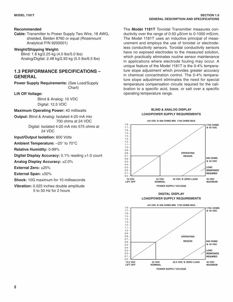
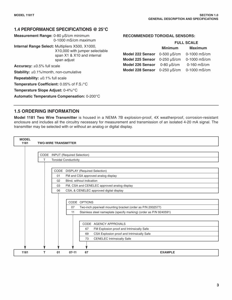
1.3 PERFORMANCE SPECIFICATIONS –GENERALPower Supply Requirements: (See Load/Supply
Chart)
Lift Off Voltage:Blind & Analog: 10 VDCDigital: 12.5 VDC
Maximum Operating Power: 40 milliwatts
Output: Blind & Analog: Isolated 4-20 mA into 700 ohms at 24 VDC
Digital: Isolated 4-20 mA into 575 ohms at24 VDC
Input/Output Isolation: 600 Volts
Ambient Temperature: –25° to 70°C
Relative Humidity: 0-99%
Digital Display Accuracy: 0.1% reading ±1.0 count
Analog Display Accuracy: ±2.0%
External Zero: ±25%
External Span: ±50%
Shock: 10G maximum for 10 milliseconds
Vibration: 0.025 inches double amplitude5 to 50 Hz for 2 hours
The Model 1181T Toroidal Transmitter measures con-ductivity over the range of 0-50 µS/cm to 0-1000 mS/cm.The Model 1181T uses an inductive principal of meas-urement and employs the use of toroidal or electrode-less conductivity sensors. Toroidal conductivity sensorshave no exposed electrodes to the measured solution,which practically eliminates routine sensor maintenancein applications where electrode fouling may occur. Aunique feature of the Model 1181T is the 0-4% tempera-ture slope adjustment which provides greater accuracyin chemical concentration control. The 0-4% tempera-ture slope adjustment eliminates the need for specialtemperature compensation circuits required for the cali-bration to a specific acid, base, or salt over a specificoperating temperature range.
BLIND & ANALOG DISPLAY
LOAD/POWER SUPPLY REQUIREMENTS
+45 VDC @ 600 OHMS MIN. 1750 OHMS MAX.
10 VDC 24 VDC 33 VDC @ ZERO LOAD 45 VDCLIFT OFF NOMINAL MAXIMUM
POWER SUPPLY VOLTAGE
1750 OHMS@ 45 VDC
600 OHMS@ 45 VDC
LOADRESISTANCEREQUIRED
1.8 –1.7 –1.6 –1.5 –1.4 –1.3 –1.2 –1.1 –1.0 –0.9 –0.8 –0.7 –0.6 –0.5 –0.4 –0.3 –0.2 –0.1 –0.0 –
OPERATINGREGION
DIGITAL DISPLAY
LOAD/POWER SUPPLY REQUIREMENTS
+45 VDC @ 600 OHMS MIN. 1750 OHMS MAX.
12.5 VDC 24 VDC 35.5 VDC @ ZERO LOAD 45 VDCLIFT OFF NOMINAL MAXIMUM
POWER SUPPLY VOLTAGE
1750 OHMS@ 45 VDC
600 OHMS@ 45 VDC
LOADRESISTANCEREQUIRED
1.8 –1.7 –1.6 –1.5 –1.4 –1.3 –1.2 –1.1 –1.0 –0.9 –0.8 –0.7 –0.6 –0.5 –0.4 –0.3 –0.2 –0.1 –0.0 –
OPERATING
REGION
3
RECOMMENDED TOROIDAL SENSORS:
FULL SCALEMinimum Maximum
Model 222 Sensor 0-500 µS/cm 0-1000 mS/cmModel 225 Sensor 0-250 µS/cm 0-1000 mS/cmModel 226 Sensor 0-80 µS/cm 0-160 mS/cmModel 228 Sensor 0-250 µS/cm 0-1000 mS/cm
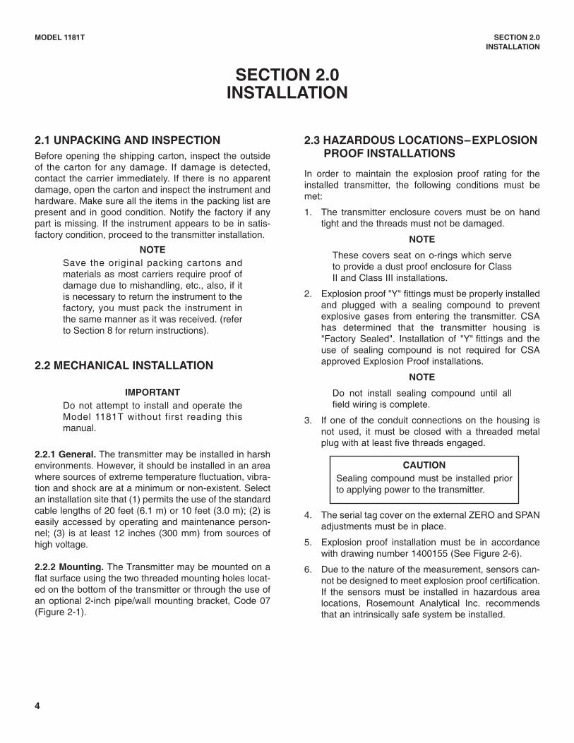
MODEL1181 TWO-WIRE TRANSMITTER
CODE INPUT (Required Selection)
T Toroidal Conductivity
CODE DISPLAY (Required Selection)
01 FM and CSA approved analog display
02 Blind, without indication
03 FM, CSA and CENELEC approved analog display
06 CSA, & CENELEC approved digital display
CODE OPTIONS
07 Two-inch pipe/wall mounting bracket (order as P/N 2002577)
11 Stainless steel nameplate (specify marking) (order as P/N 9240591)
CODE AGENCY APPROVALS
67 FM Explosion proof and Intrinsically Safe
69 CSA Explosion proof and Intrinsically Safe
73 CENELEC Intrinsically Safe
1181 T 01 07-11 67 EXAMPLE
1.5 ORDERING INFORMATIONModel 1181 Two Wire Transmitter is housed in a NEMA 7B explosion-proof, 4X weatherproof, corrosion-resistantenclosure and includes all the circuitry necessary for measurement and transmission of an isolated 4-20 mA signal. Thetransmitter may be selected with or without an analog or digital display.
MODEL 1181T SECTION 1.0GENERAL DESCRIPTION AND SPECIFICATIONS
1.4 PERFORMANCE SPECIFICATIONS @ 25°CMeasurement Range: 0-80 µS/cm minimum
0-1000 mS/cm maximum
Internal Range Select: Multipliers X500, X1000,X10,000 with jumper selectablespan X1 & X10 and internalspan adjust
Accuracy: ±0.5% full scale
Stability: ±0.1%/month, non-cumulative
Repeatability: ±0.1% full scale
Temperature Coefficient: 0.05% of F.S./°C
Temperature Slope Adjust: 0-4%/°C
Automatic Temperature Compensation: 0-200°C
4
MODEL 1181T SECTION 2.0INSTALLATION
SECTION 2.0INSTALLATION
2.1 UNPACKING AND INSPECTIONBefore opening the shipping carton, inspect the outsideof the carton for any damage. If damage is detected,contact the carrier immediately. If there is no apparentdamage, open the carton and inspect the instrument andhardware. Make sure all the items in the packing list arepresent and in good condition. Notify the factory if anypart is missing. If the instrument appears to be in satis-factory condition, proceed to the transmitter installation.
NOTESave the original packing cartons andmaterials as most carriers require proof ofdamage due to mishandling, etc., also, if itis necessary to return the instrument to thefactory, you must pack the instrument inthe same manner as it was received. (referto Section 8 for return instructions).
2.2 MECHANICAL INSTALLATION
IMPORTANTDo not attempt to install and operate theModel 1181T without first reading thismanual.
2.2.1 General. The transmitter may be installed in harshenvironments. However, it should be installed in an areawhere sources of extreme temperature fluctuation, vibra-tion and shock are at a minimum or non-existent. Selectan installation site that (1) permits the use of the standardcable lengths of 20 feet (6.1 m) or 10 feet (3.0 m); (2) iseasily accessed by operating and maintenance person-nel; (3) is at least 12 inches (300 mm) from sources ofhigh voltage.
2.2.2 Mounting. The Transmitter may be mounted on aflat surface using the two threaded mounting holes locat-ed on the bottom of the transmitter or through the use ofan optional 2-inch pipe/wall mounting bracket, Code 07(Figure 2-1).
2.3 HAZARDOUS LOCATIONS–EXPLOSIONPROOF INSTALLATIONS
In order to maintain the explosion proof rating for theinstalled transmitter, the following conditions must bemet:
1. The transmitter enclosure covers must be on handtight and the threads must not be damaged.
NOTE
These covers seat on o-rings which serveto provide a dust proof enclosure for ClassII and Class III installations.
2. Explosion proof "Y" fittings must be properly installedand plugged with a sealing compound to preventexplosive gases from entering the transmitter. CSAhas determined that the transmitter housing is"Factory Sealed". Installation of "Y" fittings and theuse of sealing compound is not required for CSAapproved Explosion Proof installations.
NOTE
Do not install sealing compound until allfield wiring is complete.
3. If one of the conduit connections on the housing isnot used, it must be closed with a threaded metalplug with at least five threads engaged.
4. The serial tag cover on the external ZERO and SPANadjustments must be in place.
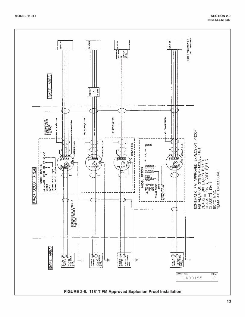
5. Explosion proof installation must be in accordancewith drawing number 1400155 (See Figure 2-6).
6. Due to the nature of the measurement, sensors can-not be designed to meet explosion proof certification.If the sensors must be installed in hazardous arealocations, Rosemount Analytical Inc. recommendsthat an intrinsically safe system be installed.
CAUTIONSealing compound must be installed priorto applying power to the transmitter.

5
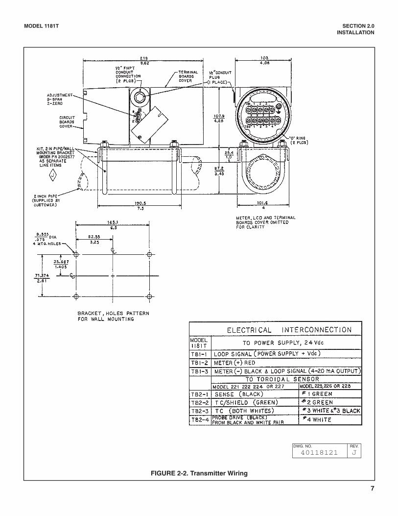
FIGURE 2-1. Mounting and Dimensional Drawing
MODEL 1181T SECTION 2.0INSTALLATION
6
MODEL 1181T SECTION 2.0INSTALLATION
2.4 WIRING–GENERAL
The transmitter is equipped with two 1¼2-inch conduitopenings, one on each side of the housing. One is for thepower supply/signal wiring and the other is for the sensorwiring.
The use of waterproof cable glands or conduit is recom-mended to prevent moisture from entering the housing. Ifconduit is used, it should be positioned to prevent con-densation from draining into the housing.
Twisted pairs are recommended for the signal cable. Thetwisted pairs should also be shielded and grounded. Thetransmitter case shall be grounded.
Signal or sensor wiring should never be run in the sameconduit or open tray with AC power, or relay actuated sig-nal cables. Keep signal or sensor wiring at least 12 inch-es from heavy electrical equipment.
NOTE
For best EMI/REI protection the powersupply/signal cable should be shielded andenclosed in an earth grounded rigid metal con-duit. Connect the cable’s outer shield to the earthground terminal near TB1, Figure 2-2.
The sensor cable should also be shielded. Thecable’s outer shield shall be connected to theearth ground terminal provided near TB1, Figure2-2. If the outer shield is braided an appropriatemetal cable gland fitting may be used to connectthe braid to earth ground via the instrument case.
A new addition to the suite of tests done toensure CE compliance is IEC 1000-4-5. This is asurge immunity test that simulates overvoltagesdue to switching and lightning transients.
In order to meet the requirements of this test,additional protection must be added to theinstrument in the form of a Transient Protectorsuch as the Rosemount Model 470D. This is a3½-inch tube with ½-inch MNPT threads on bothends. Inside the tube are gas discharge andzener diode devices to limit surges to the trans-mitter from the current loop. No additional pro-tection is needed on the sensor connections.
2.4.3 Sensor Wiring. The Sensor wiring terminals arelocated on the side of the housing designated TERMSIDE on the serial label. Remove the housing cover fromthe TERM SIDE to gain access to the terminals desig-nated TB2. Remove the optional Analog or Digital dis-play. The plug in analog display is held in by a spring clipand the digital display is held in by a locking screw.Connect the sensor wiring to TB2 terminals 1 through 4as shown on drawing 40118121 (Figure 2-2).
NOTE
Sensors are supplied with a standard cablelength of 20 feet (6.1 m) or 10 feet (3.0 m).If the standard cable length is not sufficientfor the planned installation, the use of ajunction box with extension cable is strong-ly recommended. Cutting or extending thecable may reduce performance and willvoid warranty.
2.4.2 Power and Signal Wiring. The power and signalwiring terminals are located directly above the Sensorwiring terminals and are designated TB1. TB1 alsoprovides for plugging in the optional Analog display orwiring of the optional digital display.
2.5 HAZARDOUS LOCATIONS–INTRINSICALLY SAFE INSTALLATION
To secure and maintain intrinsically safe installationfor the appropriate approval agency, the following con-ditions must be met:
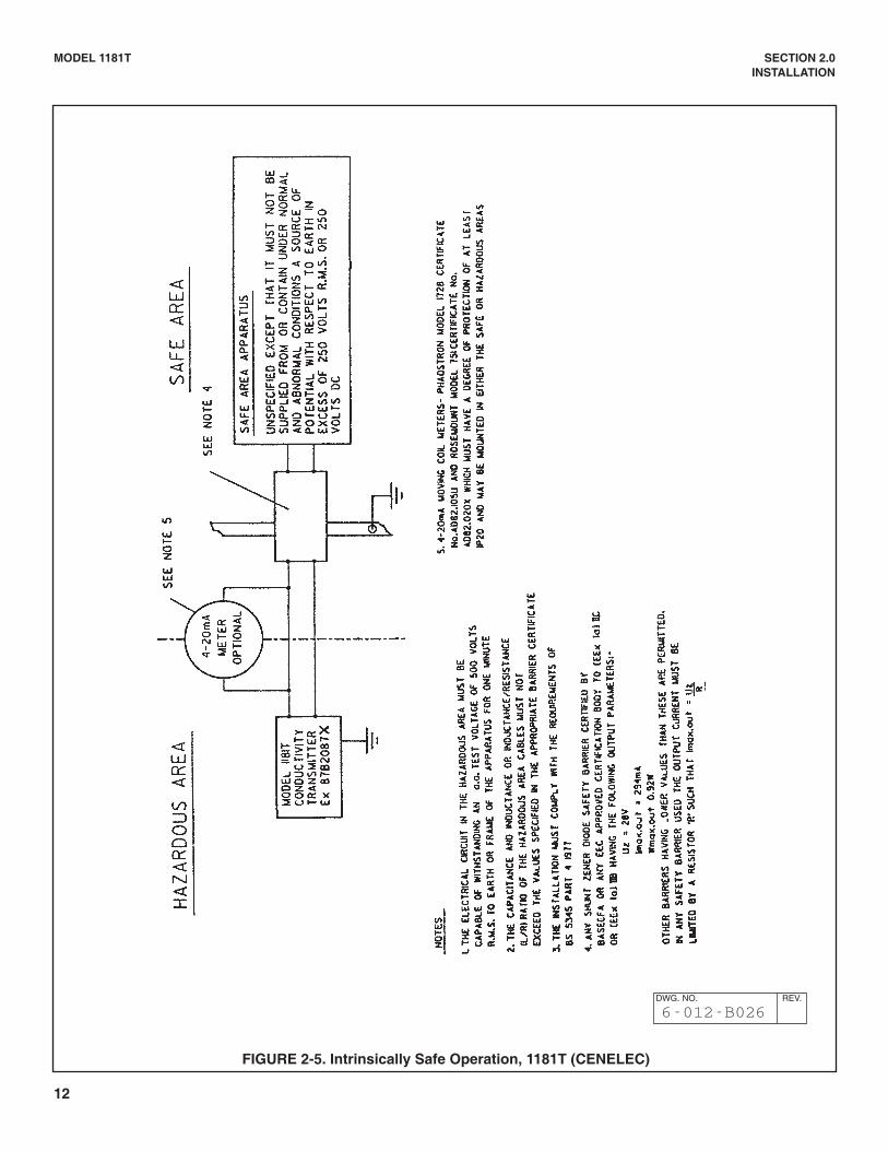
1. Code 73 must be specified when ordering CENELECunits and installation must be performed in accor-dance with Drawing Number 6-012-BO26 (Figure 2-5).
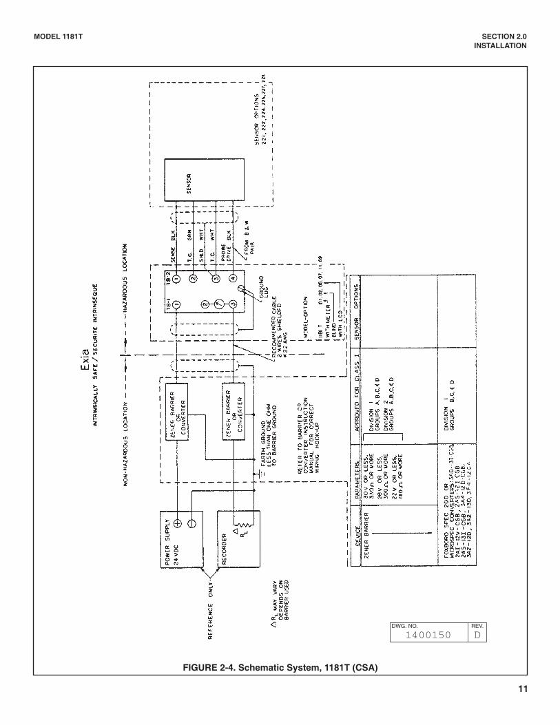
2. Code 69 must be specified when ordering CSA(Canadian Standards Association) units. Installationmust be performed in accordance with DrawingNumber 1400150 (Figure 2-4).
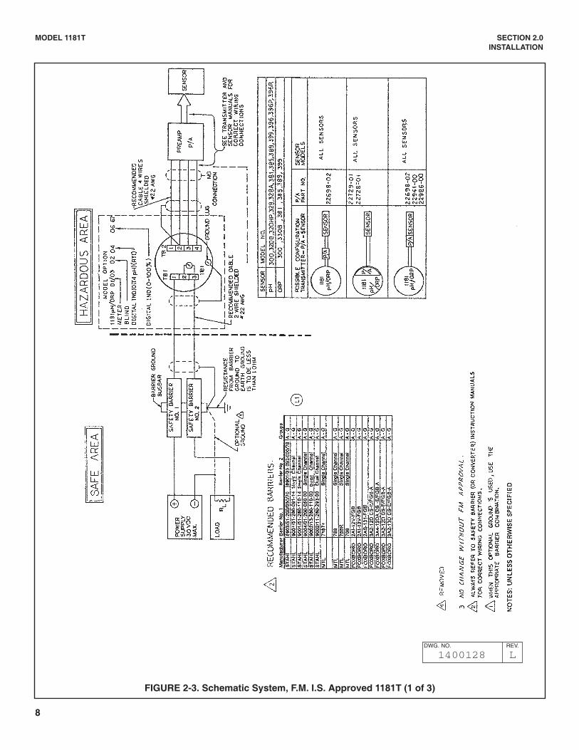
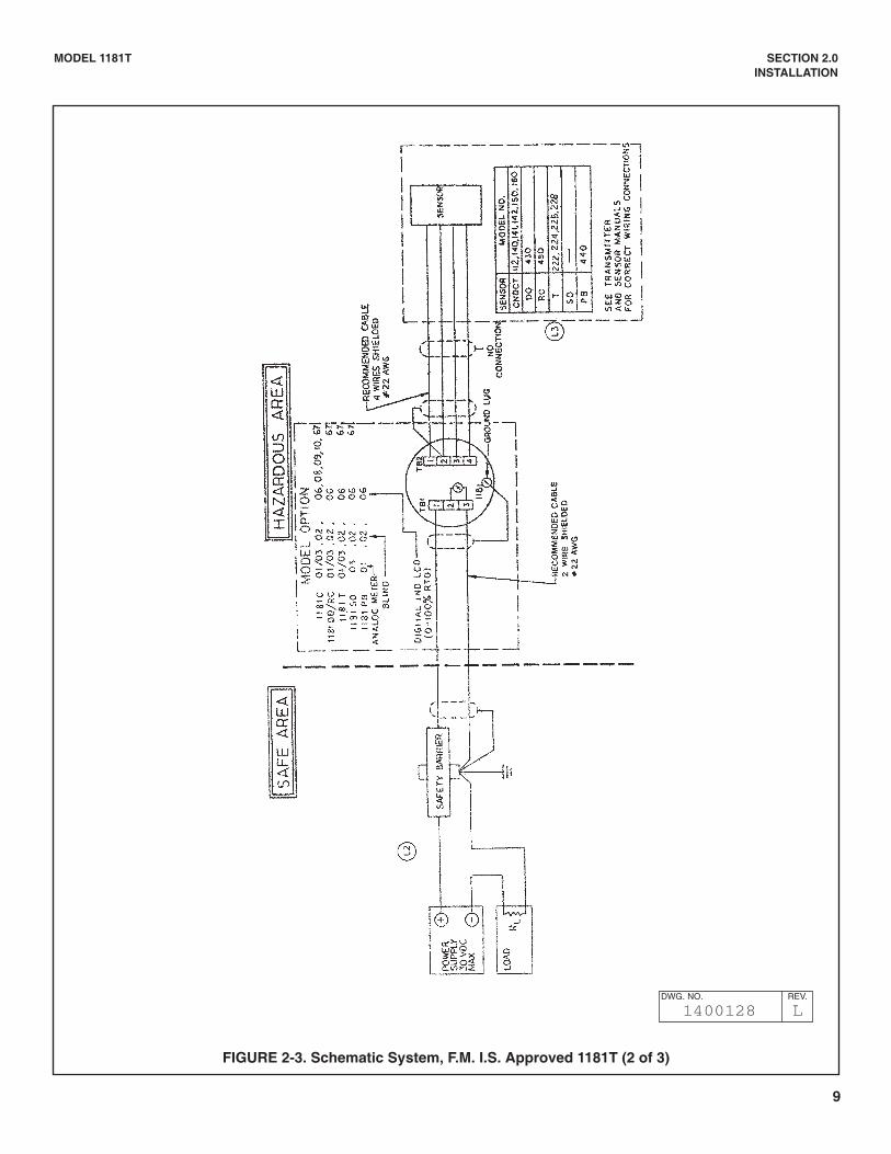
3. Code 67 must be specified when ordering F.M. units.Installation must be accordance with DrawingNumber 1400128 (Figure 2-3).
CAUTIONDo not exceed 100 feet (30.5m) distanceof total cable length between theTransmitter and the Sensor.
7
MODEL 1181T SECTION 2.0INSTALLATION
FIGURE 2-2. Transmitter Wiring
DWG. NO. REV.
40118121 J
8
MODEL 1181T SECTION 2.0INSTALLATION
FIGURE 2-3. Schematic System, F.M. I.S. Approved 1181T (1 of 3)
DWG. NO. REV.
1400128 L
9
MODEL 1181T SECTION 2.0INSTALLATION
FIGURE 2-3. Schematic System, F.M. I.S. Approved 1181T (2 of 3)
DWG. NO. REV.
1400128 L
10
MODEL 1181T SECTION 2.0INSTALLATION
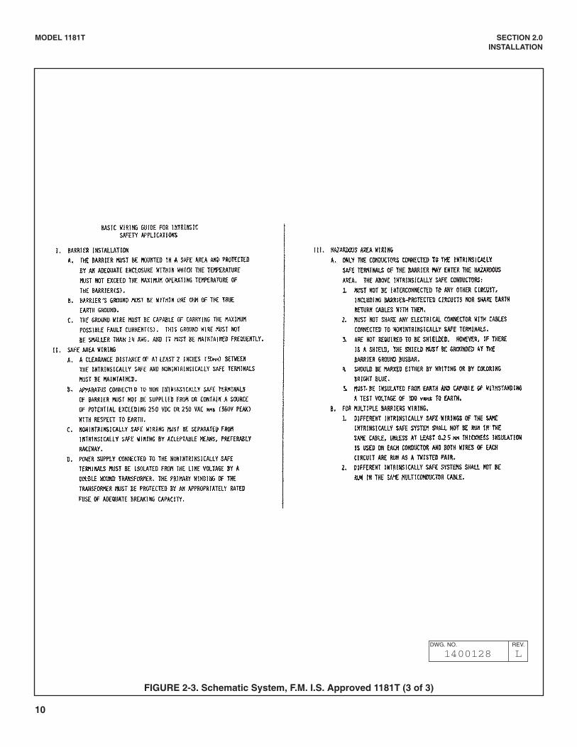
FIGURE 2-3. Schematic System, F.M. I.S. Approved 1181T (3 of 3)
DWG. NO. REV.
1400128 L
11
MODEL 1181T SECTION 2.0INSTALLATION
FIGURE 2-4. Schematic System, 1181T (CSA)
DWG. NO. REV.
1400150 D
12
MODEL 1181T SECTION 2.0INSTALLATION
FIGURE 2-5. Intrinsically Safe Operation, 1181T (CENELEC)
DWG. NO. REV.
6-012-B026
13
MODEL 1181T SECTION 2.0INSTALLATION
FIGURE 2-6. 1181T FM Approved Explosion Proof Installation
DWG. NO. REV.
1400155 C

14
15
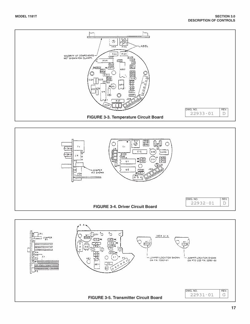
3.1 DESCRIPTION OF CONTROLS3.1.1 Internal Span Multiplier,R54, located on thetemperature PCB. The internal Span Multiplier is a 20-turn potentiometer which provides a coarse span and iscontinuously adjustable from X1 to X10. The InternalSpan Multiplier is used in conjunction with the RangeFactor Switch. This adjustment is accessed by removingthe cover on the CIRCUIT SIDE of the Transmitter(Figure 3-3).
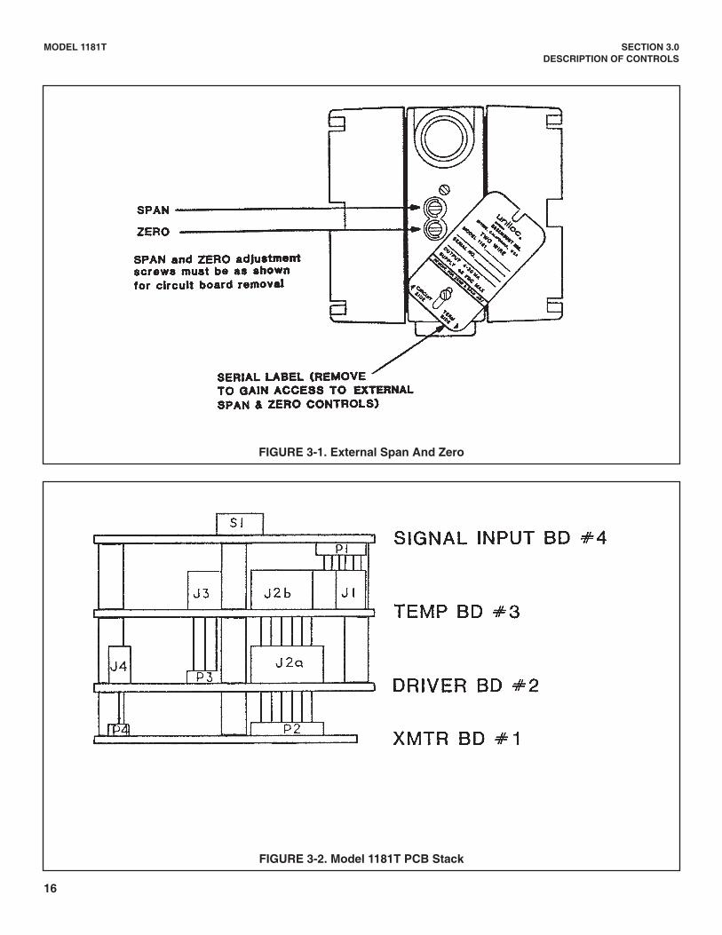
3.1.2 External Zero Pot, R18, located on the driverPCB. The External Zero is a 20-turn potentiometer usedfor fine adjustment of the 4.0 mA isolated current output.This adjustment is accessed by removing the Serial Tagon the side of the housing and is designated by a "Z"(Figure 3-1).
3.1.3 External Span Pot, R16, located on the driverPCB. The External Span is a 20-turn potentiometer usedfor fine adjustment of the 20.0 mA isolated current output.This adjustment is accessed by removing the Serial Tagon the side of the housing and is designated by an "S"(Figure 3-1).
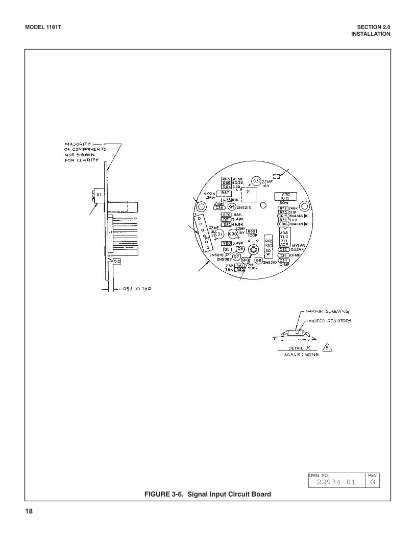
3.1.4 Range Factor Switch, located on the input PCB.The Range Factor Switch is comprised of three dipswitches: S1, S2, and S3. Different full scale ranges maybe obtained by setting the switches to the desired posi-tions. The Range Factor Switches determine the maxi-mum available full scale conductivity range (Figure 4-1).
3.1.5 Range Jumper, located on the driver PCB.This jumper increases the range of the Model 1181T. Fora multiplier of X1, place the jumper in W2 position. For amultiplier of X10 place the jumper in W3 position (Figure3-4).
MODEL 1181T SECTION 3.0DESCRIPTION OF CONTROLS
SECTION 3.0DESCRIPTION OF CONTROLS
3.1.6 Temperature Slope Adjustment, R46, locatedon the temperature PCB. Each conductive solution hasits own set of conductivity vs percent concentrationcurves which change with temperature change. Thefunction of the temperature slope adjustment is to cali-brate the temperature compensation curve to a specificsolution over the operating temperature range. The con-ductivity indication is corrected along the calibrated tem-perature slope to a 25°C reference temperature. Whenthe temperature slope adjustment is set to 0% °C, thetemperature compensator is disabled. It is very impor-tant then that the process temperature be at or near25°C (Figure 3-3).
3.1.7 Analog/LCD Operation Jumper, W1, located onthe transmitter PCB. When the jumper is in the W1 posi-tion, the 1181T will operate only with an analog meter oras a blind unit. But when the jumper is in the oppositeposition or is removed, the 1181T will operate only withan LCD (Figure 3-5).
3.1.8 Sensor Zero, R11, located on the driver PCB.The Sensor Zero potentiometer is used to offset cableresistance measured as conductivity. The Sensor Zero isused upon completion of all field wiring and prior to finecalibration of the 4.0 mA output with the External Zero(Figure 3-4).
16
MODEL 1181T SECTION 3.0DESCRIPTION OF CONTROLS
FIGURE 3-1. External Span And Zero
FIGURE 3-2. Model 1181T PCB Stack
17
MODEL 1181T SECTION 3.0DESCRIPTION OF CONTROLS
FIGURE 3-4. Driver Circuit Board
FIGURE 3-5. Transmitter Circuit Board
FIGURE 3-3. Temperature Circuit Board
DWG. NO. REV.
22933-01 D
DWG. NO. REV.
22932-01 D
DWG. NO. REV.
22931-01 G
18
MODEL 1181T SECTION 2.0INSTALLATION
FIGURE 3-6. Signal Input Circuit Board
DWG. NO. REV.
22934-01 G
19
MODEL 1181T SECTION 4.0CONFIGURATION
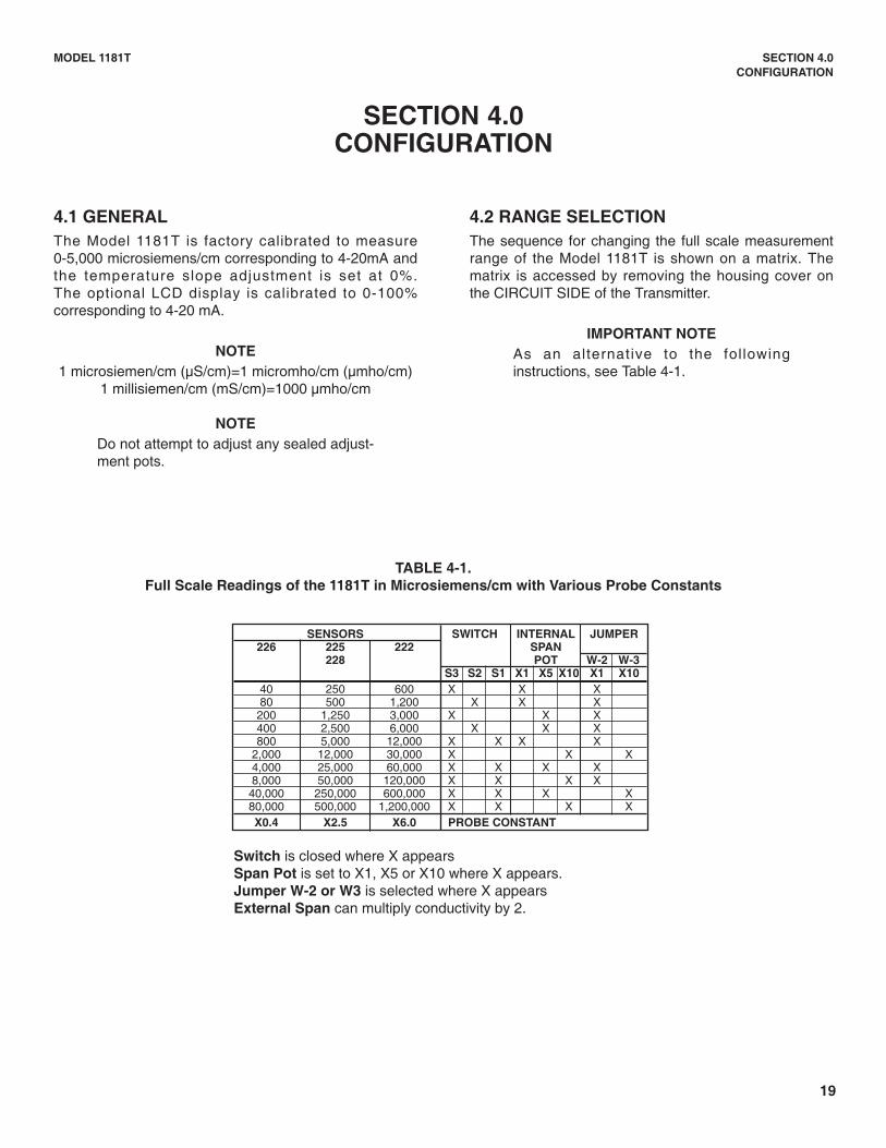
4.2 RANGE SELECTIONThe sequence for changing the full scale measurementrange of the Model 1181T is shown on a matrix. Thematrix is accessed by removing the housing cover onthe CIRCUIT SIDE of the Transmitter.
IMPORTANT NOTEAs an alternative to the fol lowinginstructions, see Table 4-1.
4.1 GENERALThe Model 1181T is factory calibrated to measure0-5,000 microsiemens/cm corresponding to 4-20mA andthe temperature slope adjustment is set at 0%.The optional LCD display is calibrated to 0-100%corresponding to 4-20 mA.
NOTE1 microsiemen/cm (µS/cm)=1 micromho/cm (µmho/cm)
1 millisiemen/cm (mS/cm)=1000 µmho/cm
NOTEDo not attempt to adjust any sealed adjust-ment pots.
SECTION 4.0CONFIGURATION
TABLE 4-1.Full Scale Readings of the 1181T in Microsiemens/cm with Various Probe Constants
SENSORS SWITCH INTERNAL JUMPER226 225 222 SPAN
228 POT W-2 W-3S3 S2 S1 X1 X5 X10 X1 X10
40 250 600 X X X80 500 1,200 X X X
200 1,250 3,000 X X X400 2,500 6,000 X X X800 5,000 12,000 X X X X
2,000 12,000 30,000 X X X4,000 25,000 60,000 X X X X8,000 50,000 120,000 X X X X
40,000 250,000 600,000 X X X X80,000 500,000 1,200,000 X X X XX0.4 X2.5 X6.0 PROBE CONSTANT
Switch is closed where X appears Span Pot is set to X1, X5 or X10 where X appears.Jumper W-2 or W3 is selected where X appears External Span can multiply conductivity by 2.
20
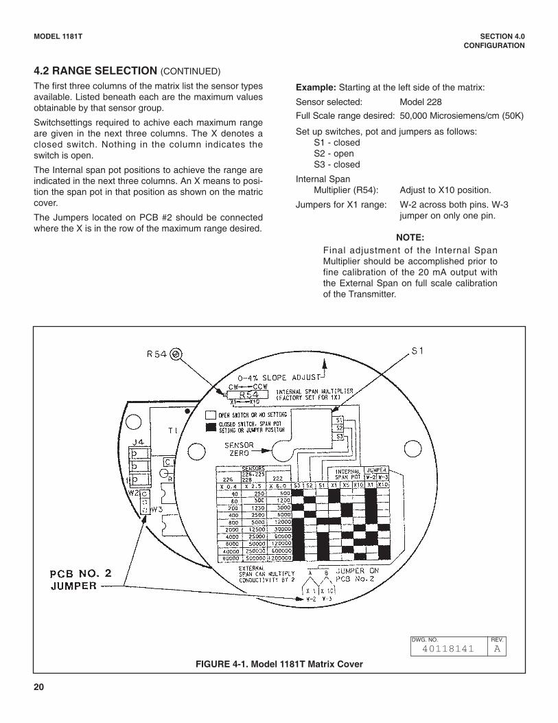
4.2 RANGE SELECTION (CONTINUED)
The first three columns of the matrix list the sensor typesavailable. Listed beneath each are the maximum valuesobtainable by that sensor group.
Switchsettings required to achive each maximum rangeare given in the next three columns. The X denotes aclosed switch. Nothing in the column indicates theswitch is open.
The Internal span pot positions to achieve the range areindicated in the next three columns. An X means to posi-tion the span pot in that position as shown on the matriccover.
The Jumpers located on PCB #2 should be connectedwhere the X is in the row of the maximum range desired.
Example: Starting at the left side of the matrix:
Sensor selected: Model 228
Full Scale range desired: 50,000 Microsiemens/cm (50K)
Set up switches, pot and jumpers as follows:S1 - closedS2 - openS3 - closed
Internal SpanMultiplier (R54): Adjust to X10 position.
Jumpers for X1 range: W-2 across both pins. W-3 jumper on only one pin.
NOTE:Final adjustment of the Internal SpanMultiplier should be accomplished prior tofine calibration of the 20 mA output withthe External Span on full scale calibrationof the Transmitter.
MODEL 1181T SECTION 4.0CONFIGURATION
FIGURE 4-1. Model 1181T Matrix Cover
DWG. NO. REV.
40118141 A
21
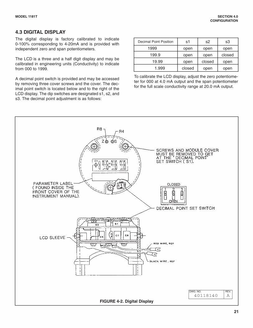
FIGURE 4-2. Digital Display
4.3 DIGITAL DISPLAYThe digital display is factory calibrated to indicate0-100% corresponding to 4-20mA and is provided withindependent zero and span potentiometers.
The LCD is a three and a half digit display and may becalibrated in engineering units (Conductivity) to indicatefrom 000 to 1999.
A decimal point switch is provided and may be accessedby removing three cover screws and the cover. The dec-imal point switch is located below and to the right of theLCD display. The dip switches are designated s1, s2, ands3. The decimal point adjustment is as follows:
To calibrate the LCD display, adjust the zero potentiome-ter for 000 at 4.0 mA output and the span potentiometerfor the full scale conductivity range at 20.0 mA output.
Decimal Point Position s1 s2 s3
1999 open open open
199.9 open open closed
19.99 open closed open
1.999 closed open open
MODEL 1181T SECTION 4.0CONFIGURATION
DWG. NO. REV.
40118140 A
22
D. Take a grab sample and measure its conductivity atthe minimum process temperature in the laboratory.Record the conductivity value and the temperature.
E. Elevate the temperature of the grab sample to themaximum process temperature. Record the conductivityvalue and the temperature.
F. Then, calculate % slope adjustment by using thefollowing formula:
Conductivity Tmax% SLOPE/°C= ( Conductivity Tmin–1)
³TX100
Where: Conductivity Tmax is the conductivity at themaximum process temperature, Conductivity Tmin is theconductivity at lower process temperature, and the ³T isthe difference between the maximum temperature andminimum process temperature.
EXAMPLE:
( 45K–1)X100
35K% SLOPE/°C=
60–50=10=2.8%/°C
G. Set the Temperature Slope Adjustment, R46, to thecorrect slope adjustment as determined by computingthe formula in Step F above.
4.4 TEMPERATURE SLOPE ADJUSTMENTFollowing are the typical temperature slopes for Acids,Bases and Salts. For greater accuracy the temperatureslope for an unknown solution may be determined in alaboratory with a portable conductivity analyzer or formore precision with the Model 1181T and associatedsensor.
Acids: 1.0 - 1.6% / °CBases: 1.8 - 2.2% / °CSalts: 2.2 - 3.0% / °CNeutral Water: 2.0% / °C
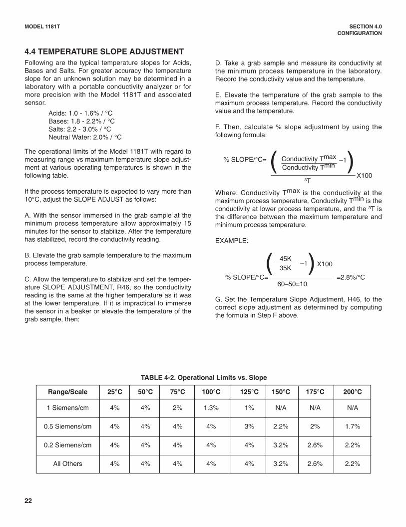
The operational limits of the Model 1181T with regard tomeasuring range vs maximum temperature slope adjust-ment at various operating temperatures is shown in thefollowing table.
If the process temperature is expected to vary more than10°C, adjust the SLOPE ADJUST as follows:
A. With the sensor immersed in the grab sample at theminimum process temperature allow approximately 15minutes for the sensor to stabilize. After the temperaturehas stabilized, record the conductivity reading.
B. Elevate the grab sample temperature to the maximumprocess temperature.
C. Allow the temperature to stabilize and set the temper-ature SLOPE ADJUSTMENT, R46, so the conductivityreading is the same at the higher temperature as it wasat the lower temperature. If it is impractical to immersethe sensor in a beaker or elevate the temperature of thegrab sample, then:
Range/Scale 25°C 50°C 75°C 100°C 125°C 150°C 175°C 200°C
1 Siemens/cm 4% 4% 2% 1.3% 1% N/A N/A N/A
0.5 Siemens/cm 4% 4% 4% 4% 3% 2.2% 2% 1.7%
0.2 Siemens/cm 4% 4% 4% 4% 4% 3.2% 2.6% 2.2%
All Others 4% 4% 4% 4% 4% 3.2% 2.6% 2.2%
TABLE 4-2. Operational Limits vs. Slope
MODEL 1181T SECTION 4.0CONFIGURATION
23
MODEL 1181T SECTION 5.0START UP AND CALIBRATION
The Model 1181T may be calibrated by (1) using either aconductivity standard or a sample of the process, (2) in-situ calibration by grab sample analysis, or (3) calibra-tion using decade box or resistors to simulateconductance. Calibration using a process sample willprovide the greatest accuracy.
5.1 CALIBRATION USING A CONDUCTIVITYSTANDARD OR PROCESS SAMPLE
1. Complete all field wiring as described in Section 2.0.
2. Configure the Transmitter as described in Section4.0.
3. With the Sensor in Air
A. Adjust the Sensor Zero, R11, for coarse calibra-tion of the 4.0 mA current output.
B. Adjust the External Zero for fine calibration of the4.0 mA current output.
C. Optional, Adjust the LCD Zero Potentiometer,R8, for 000.
4. Place the Sensor in a container filled with aConductivity Standard or Process Sample.
NOTEAll sides of the sensor should be at leastone sensor diameter from the walls of thesample container. It is important that thesensor position in the sample containerapproximate the actual mounting arrange-ment because the sensor cell constant isaffected by its immediate environment.
Insure no air bubbles are trapped in thecenter hole.
5. Adjust the Internal Span Multiplier, R54, for coarseadjustment of the output current value in milliamps ofthe known Conductivity Standard or to the measuredvalue of the process sample.
mA output =CS( CFS
X16) +4
Cs = Conductivity of Standard Solution or Process
Sample.Cfs = Full Scale Conductivity Range Selected.
EXAMPLE: The selected full scale conductivity range is5000 microsiemens/cm and the standard solution used is2000 microsiemens/cm.
mA Output =(2000 X16) + 4 = 10.4 mA
5000
6. Adjust the Temperature Slope potentiometer, R46, tothe calculated slope value.
7. Fine Adjust the current output calculated in Step 5with the External Span.
8. Optional; Adjust the LCD display Span potentiome-ter, R4, either to (1) a percent indication or (2) to thevalue of the Conductivity Standard or the measuredconductivity value of the process sample.
LCD or Analog Display = CS( CFS ) X100
EXAMPLE: ( 2000 )5000
X100 = 40%
9. Install the Sensor into the process. Final calibrationmay be done with the External Span to a processgrab sample.
SECTION 5.0START UP AND CALIBRATION
24
MODEL 1181T SECTION 5.0START UP AND CALIBRATION
5.2 IN-SITU CALIBRATION BYGRAB SAMPLE ANALYSIS
1. Complete all field wiring as described in Section 2.0.
2. Configure the Transmitter as described in Section4.0.
NOTE
If extension cable is used, disconnect thesense wire on the sensor side of thejunction box. If extension cable is notused, disconnect the sense wire at thetransmitter.
3. Adjust the External Zero for fine calibration of the 4.0mA current output.
4. Optional; Adjust the LCD Zero Potentiometer, R8, for000.
5. Re-connect the sensor sense wire at the junctionbox.
6. Take a grab sample of the process and measure itsConductivity value using a calibrated portable ana-lyzer having a reference temperature of 25°C. Notethe Transmitter Indication for reference.
CAUTIONOlder portables may have a reference tem-perature of 18°C which will cause variancein the measured value.
7. Adjust the Internal Span Multiplier, R54 for coarseadjustment of the current output in milliamps to themeasured value of the process sample.
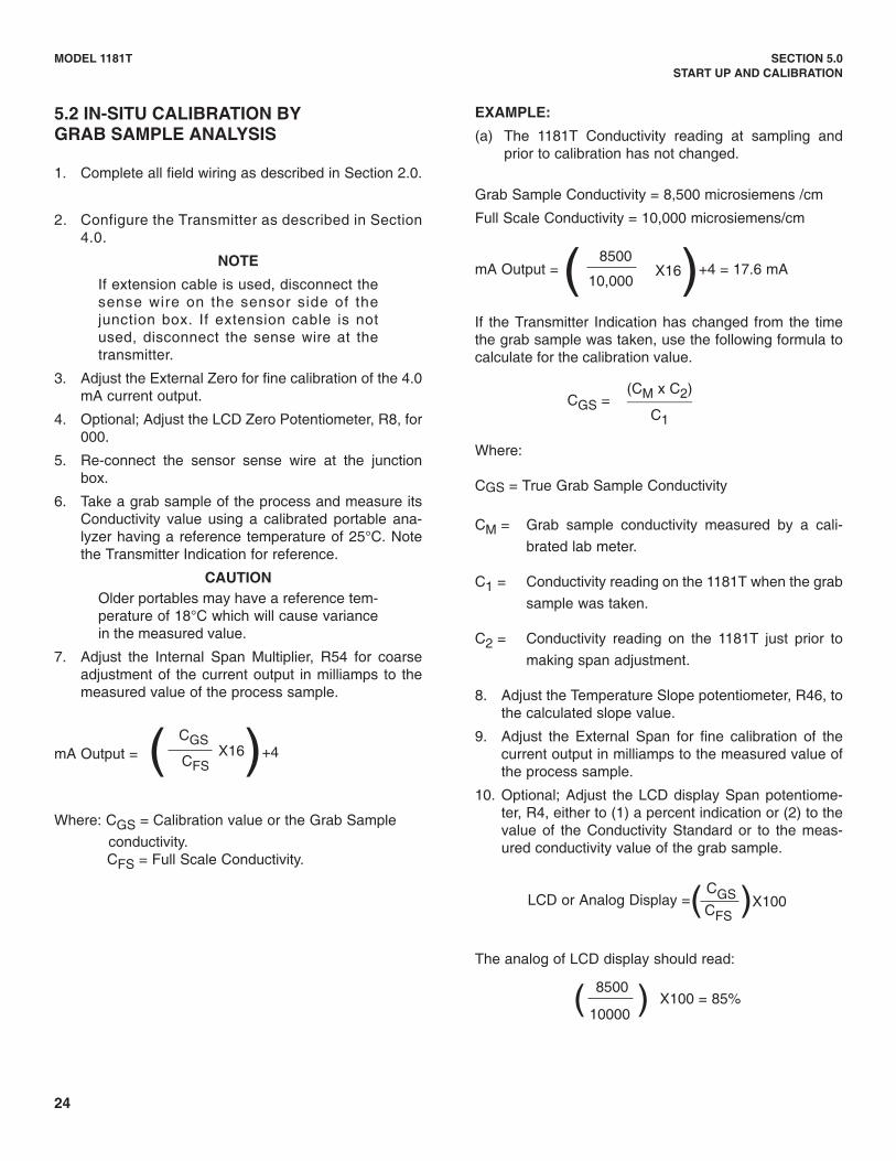
CGSmA Output = ( CFS
X16)+4
Where: CGS = Calibration value or the Grab Sample
conductivity.CFS = Full Scale Conductivity.
EXAMPLE:
(a) The 1181T Conductivity reading at sampling andprior to calibration has not changed.
Grab Sample Conductivity = 8,500 microsiemens /cm
Full Scale Conductivity = 10,000 microsiemens/cm
8500mA Output = ( 10,000
X16)+4 = 17.6 mA
If the Transmitter Indication has changed from the timethe grab sample was taken, use the following formula tocalculate for the calibration value.
(CM x C2)CGS = ________
C1
Where:
CGS = True Grab Sample Conductivity
CM = Grab sample conductivity measured by a cali-
brated lab meter.
C1 = Conductivity reading on the 1181T when the grab
sample was taken.
C2 = Conductivity reading on the 1181T just prior to
making span adjustment.
8. Adjust the Temperature Slope potentiometer, R46, tothe calculated slope value.
9. Adjust the External Span for fine calibration of thecurrent output in milliamps to the measured value ofthe process sample.
10. Optional; Adjust the LCD display Span potentiome-ter, R4, either to (1) a percent indication or (2) to thevalue of the Conductivity Standard or to the meas-ured conductivity value of the grab sample.
LCD or Analog Display =( CGS )X100CFS
The analog of LCD display should read:
( 8500 ) X100 = 85%10000
25
MODEL 1181T SECTION 5.0START UP AND CALIBRATION
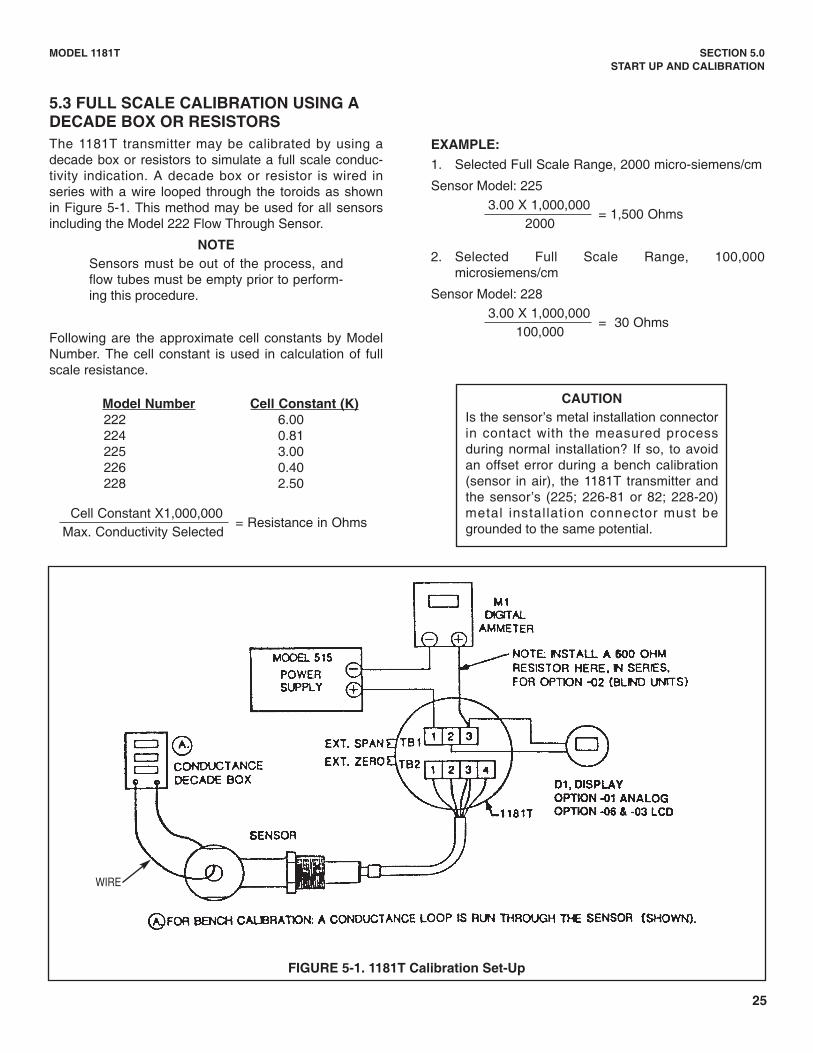
5.3 FULL SCALE CALIBRATION USING ADECADE BOX OR RESISTORSThe 1181T transmitter may be calibrated by using adecade box or resistors to simulate a full scale conduc-tivity indication. A decade box or resistor is wired inseries with a wire looped through the toroids as shownin Figure 5-1. This method may be used for all sensorsincluding the Model 222 Flow Through Sensor.
NOTESensors must be out of the process, andflow tubes must be empty prior to perform-ing this procedure.
Following are the approximate cell constants by ModelNumber. The cell constant is used in calculation of fullscale resistance.
Model Number Cell Constant (K)222 6.00224 0.81225 3.00226 0.40228 2.50
Cell Constant X1,000,000= Resistance in Ohms
Max. Conductivity Selected
EXAMPLE:
1. Selected Full Scale Range, 2000 micro-siemens/cm
Sensor Model: 2253.00 X 1,000,000
= 1,500 Ohms2000
2. Selected Full Scale Range, 100,000microsiemens/cm
Sensor Model: 2283.00 X 1,000,000
= 30 Ohms100,000
CAUTIONIs the sensor’s metal installation connectorin contact with the measured processduring normal installation? If so, to avoidan offset error during a bench calibration(sensor in air), the 1181T transmitter andthe sensor’s (225; 226-81 or 82; 228-20)metal installation connector must begrounded to the same potential.
FIGURE 5-1. 1181T Calibration Set-Up
WIRE
26
MODEL 1181T SECTION 6.0THEORY OF OPERATION
SECTION 6.0THEORY OF OPERATION
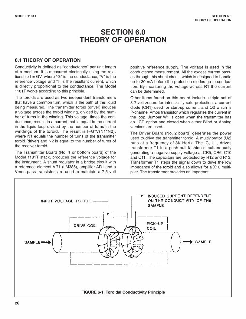
6.1 THEORY OF OPERATIONConductivity is defined as “conductance” per unit lengthof a medium. It is measured electrically using the rela-tionship I = GV, where “G” is the conductance, “V” is thereference voltage and “I” is the resultant current, whichis directly proportional to the conductance. The Model1181T works according to this principle.
The toroids are used as two independent transformersthat have a common turn, which is the path of the liquidbeing measured. The transmitter toroid (driver) inducesa voltage across the toroid winding, divided by the num-ber of turns in the winding. This voltage, times the con-ductance, results in a current that is equal to the currentin the liquid loop divided by the number of turns in thewindings of the toroid. The result is I=G*V(N1*N2),where N1 equals the number of turns of the transmittertoroid (driver) and N2 is equal to the number of turns ofthe receiver toroid.
The Transmitter Board (No. 1 or bottom board) of theModel 1181T stack, produces the reference voltage forthe instrument. A shunt regulator in a bridge circuit witha reference element VR1 (LM385), amplifier AR1 and aVmos pass transistor, are used to maintain a 7.5 volt
positive reference supply. The voltage is used in theconductance measurement. All the excess current pass-es through this shunt circuit, which is designed to handleup to 30 mA before the protection diodes go to conduc-tion. By measuring the voltage across R1 the currentcan be determined.
Other items found on this board include a triple set of8.2 volt zeners for intrinsically safe protection, a currentdiode (CR1) used for start-up current, and Q2 which isP-channel Vmos transistor which regulates the current inthe loop. Jumper W1 is open when the transmitter hasan LCD option and closed when either Blind or Analogversions are used.
The Driver Board (No. 2 board) generates the powerused to drive the transmitter toroid. A multivibrator (U2)runs at a frequency of 8K Hertz. The IC, U1, drivestransformer T1 in a push-pull fashion simultaneouslygenerating a negative supply voltage at CR5, CR6, C10and C11. The capacitors are protected by R12 and R13.Transformer T1 steps the signal down to drive the lowimpedance of the toroid and also allows for a X10 multi-plier. The transformer provides an important
FIGURE 6-1. Toroidal Conductivity Principle
27
MODEL 1181T SECTION 6.0THEORY OF OPERATION
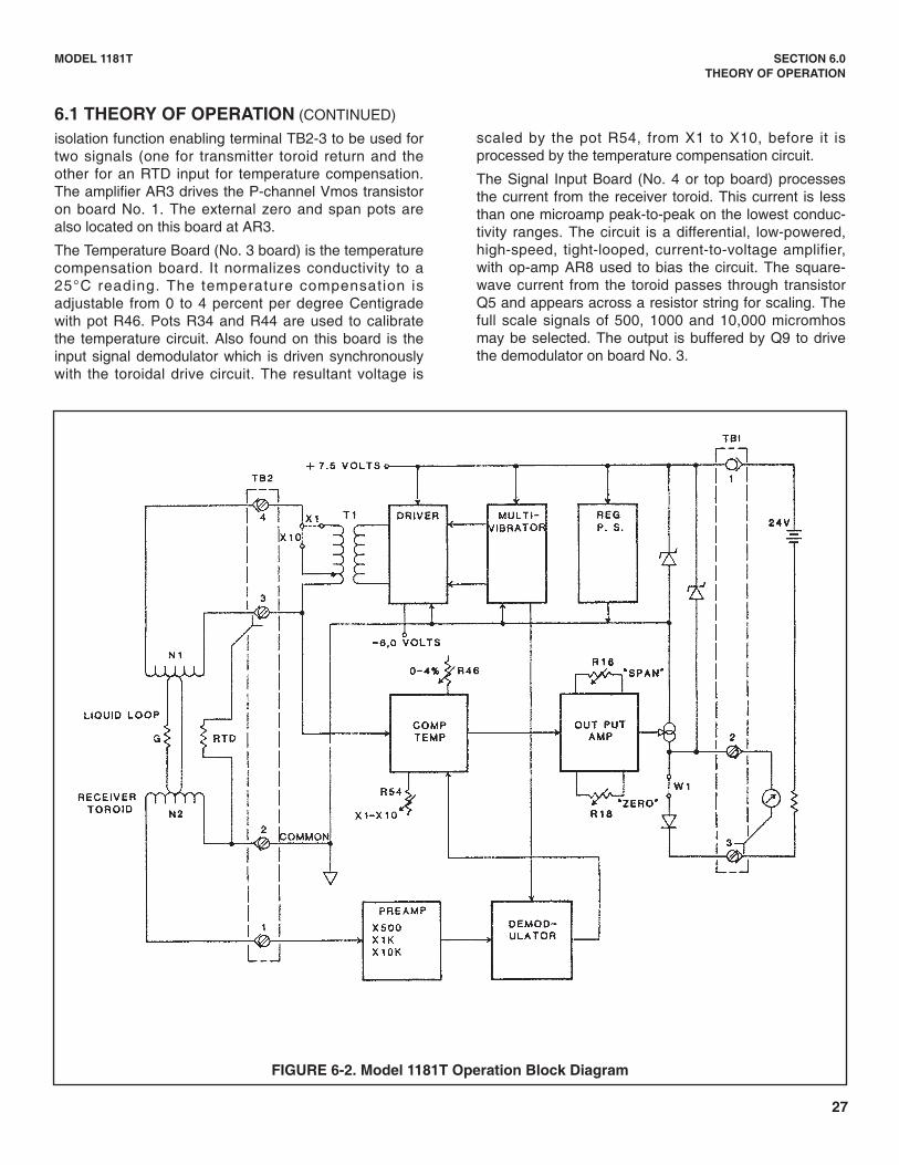
scaled by the pot R54, from X1 to X10, before it isprocessed by the temperature compensation circuit.
The Signal Input Board (No. 4 or top board) processesthe current from the receiver toroid. This current is lessthan one microamp peak-to-peak on the lowest conduc-tivity ranges. The circuit is a differential, low-powered,high-speed, tight-looped, current-to-voltage amplifier,with op-amp AR8 used to bias the circuit. The square-wave current from the toroid passes through transistorQ5 and appears across a resistor string for scaling. Thefull scale signals of 500, 1000 and 10,000 micromhosmay be selected. The output is buffered by Q9 to drivethe demodulator on board No. 3.
FIGURE 6-2. Model 1181T Operation Block Diagram
6.1 THEORY OF OPERATION (CONTINUED)
isolation function enabling terminal TB2-3 to be used fortwo signals (one for transmitter toroid return and theother for an RTD input for temperature compensation.The amplifier AR3 drives the P-channel Vmos transistoron board No. 1. The external zero and span pots arealso located on this board at AR3.
The Temperature Board (No. 3 board) is the temperaturecompensation board. It normalizes conductivity to a25°C reading. The temperature compensation isadjustable from 0 to 4 percent per degree Centigradewith pot R46. Pots R34 and R44 are used to calibratethe temperature circuit. Also found on this board is theinput signal demodulator which is driven synchronouslywith the toroidal drive circuit. The resultant voltage is
28
MODEL 1181T SECTION 6.0THEORY OF OPERATION
6.2 CIRCUIT DESCRIPTION (Figure 6-3)
VR1 and the Vmos pass transistor are used to maintainthe reference voltage (peak voltage of the square wave)at 7.5 volts D.C.
This voltage is sent to the multivibrator U2, which cre-ates a square wave (8K Hertz frequency).
This square wave is passed to the power voltage driverV1 and is stepped-up by T1. It is then sent to the drivertoroid.
The voltage through the driver coil induces a current intothe process solution.
The current of the process induces a current flow in thereceiver (pick-up) coil that is proportional to the conduc-tivity of the process solution. This current is then differ-entially amplified by Q6, Q7, Q8 and Q9.
AR8 biases the circuit and Q5 passes the current, whichis adjusted for ranges of 500, 1000 and 10,000 by amicroswitch selection to a voltage divider (R64, R65,R66 and R67).
This adjusted current is passed through Q9, which is abuffer to the demodulator U4, AR6-D.
AR6-D and U14 converts the 8K hertz current to a directcurrent voltage which is still proportional to the conduc-tivity of the process fluid.
The voltage is further adjusted by the setting of R54,which is the span factor adjust from X1 to X10.
The voltage is then passed to the output AR6-C. Thevoltage at that point is modified, based on the input fromAR6-B (temperature compensation circuit).
As the resistance of the temperature compensator (T.C.)at the sensor changes with respect to the processtemperature (input at TB-3), it causes a change to thefeedback loop gain of the T.C. circuit. This, in turn,changes the gain of the T.C. circuit, which causesa change in the voltage output at AR6-C.
The T.C. corrected voltage output from AR6-C is furtheradjusted by the External Span and Zero Pots (R16and R18), then passed from AR3 to the gate of Q2(P-channel Vmos).
As the voltage changes at the gate of Q2 with respect toconductivity/temperature, Q2 changes currentflow through the loop. This provides a 4 to 20 milliampoutput.
29
MODEL 1181T SECTION 6.0THEORY OF OPERATION
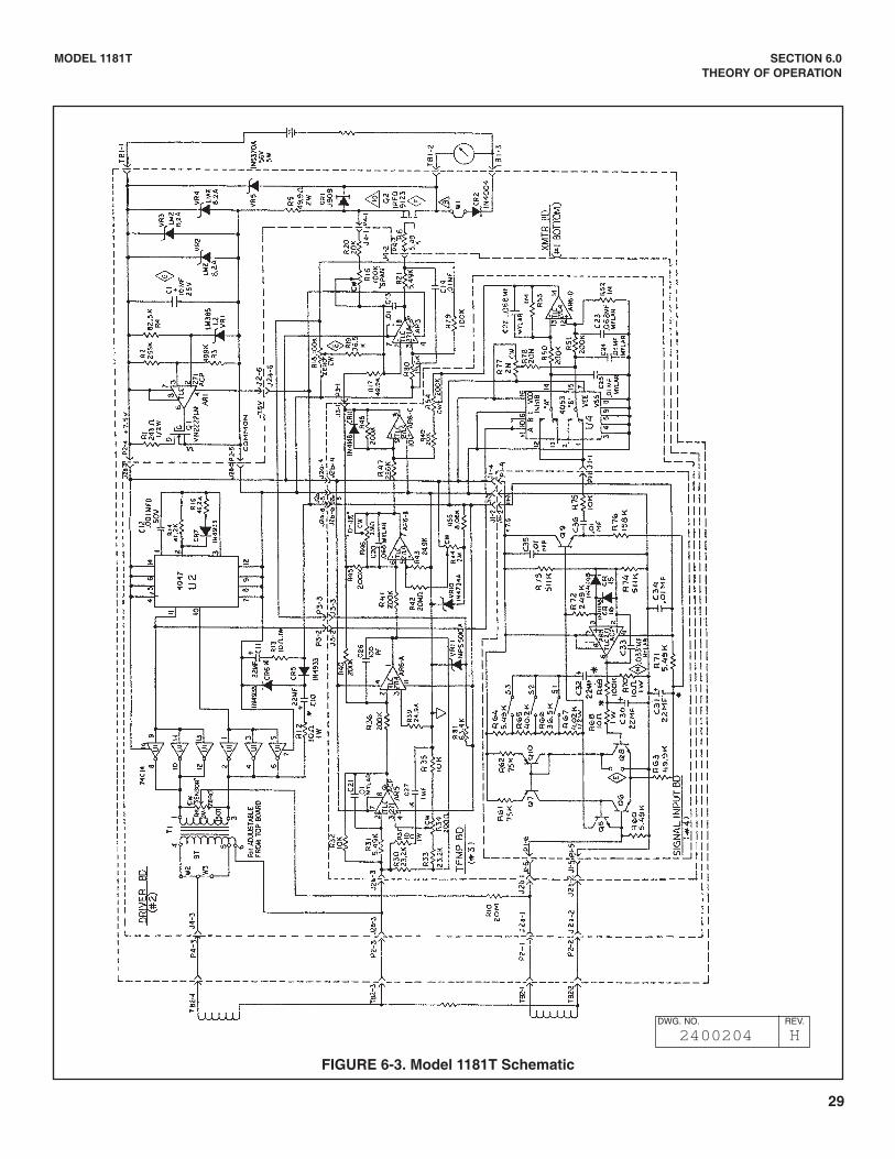
FIGURE 6-3. Model 1181T Schematic
DWG. NO. REV.
2400204 H
30
MODEL 1181T SECTION 7.0DISASSEMBLY/REASSEMBLY PROCEDURE
SECTION 7.0DISASSEMBLY/REASSEMBLY PROCEDURE
7.1 DISASSEMBLY PROCEDUREDisconnect the power to the transmitter prior to dis-assembly. (Refer to Figure 9-1 for item numbers alsosee Figure 3-1).
1. Remove covers (1) and (18) or meter housing cover(19) from housing (3). Save O-rings (2); discard ifdamaged.
2. Loosen screws retaining the serial label, and thenrotate to gain access to the Span and Zero pots.
3. Align the Span and Zero adjusting screws (4), so theslots are horizontal, pointing end cap to end cap.
4. In circuit side of housing (3) remove the circuit boardretaining screws, washers and matrix cover (10). Thematrix cover is secured to screws by nylon splitwashers. Remove the screws in equal increments,so the matrix cover is not damaged.
5. Pull straight out on the signal conditioning boardassembly (9) to remove circuit boards from hous-ing (3).
6. To separate the individual boards, remove the retain-ing screw located on the terminal side of the trans-mitter board (6).
7. Remove each printed circuit board assembly bypulling straight out from their respective connectors.
7.2 REASSEMBLY PROCEDURE1. Assemble the circuit board assemblies (6, 7, 8, 9) by
first aligning the connectors with the respective pins,and then pushing straight in. Install screw whichholds circuit board assemblies together.
2. Align the Zero and Span adjusting screws (4) on thehousing (3) to the horizontal position, slots pointingend cap to end cap (see Figure 4-1).
3. Align the Zero and Span potentiometers located onthe driver circuit board (7) to the horizontal position,with blades perpendicular to PCB's (6) and (7).
4. Place the circuit board assemblies (6, 7, 8, 9) intohousing by first aligning the connector pins with theterminal receptacles in the base of the housing (3)and then pushing straight in on the signal condition-ing board (9).
5. Install the matrix cover (10) and secure with screwsand washers. The matrix cover is secured to thescrews with nylon split washers, so install the screwsin equal increments, so the matrix cover is not dam-aged.
6. Inspect the thread connections on housing (3) tomake sure five undamaged threads will fully engage.
7. Replace O-rings (2) on housing (3). Use newO-rings if the old ones were damaged.
8. Install covers (1, 18) or meter housing (19) on trans-mitter housing (3).
9. Apply power to the transmitter and perform theappropriate calibration procedure if necessary.
31
MODEL 1181T SECTION 8.0TROUBLESHOOTING
SECTION 8.0TROUBLESHOOTING
8.1 GENERALThis section covers the trouble-shooting and mainte-nance instructions for the Model 1181T. This transmitterhas no moving parts and requires minimum mainte-nance. Procedures for calibrating the Model 1181T isgiven in Section 5.0 and generally the only operationtype "maintenance" required to keep the units in goodoperating condition.
NOTEIf downtime is of critical concern, a fullcomplement of spare parts is recom-mend-ed. (See Section 9.0, spare parts).
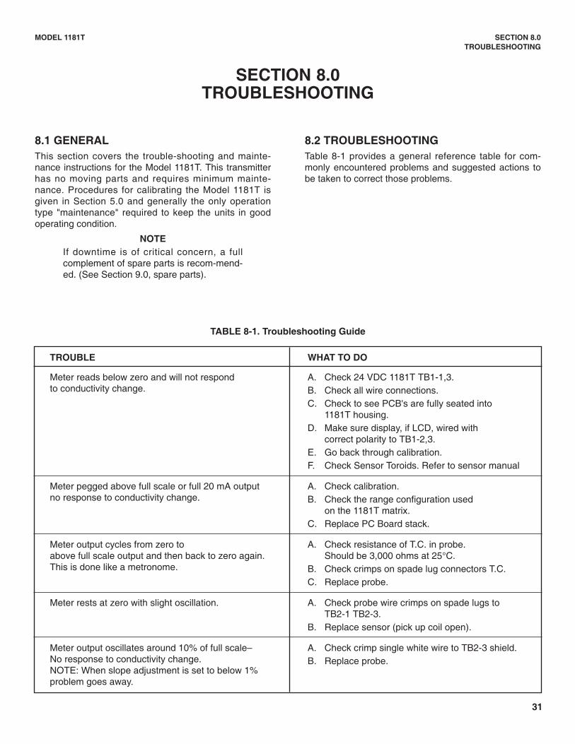
8.2 TROUBLESHOOTINGTable 8-1 provides a general reference table for com-monly encountered problems and suggested actions tobe taken to correct those problems.
TROUBLE WHAT TO DO
Meter reads below zero and will not respond A. Check 24 VDC 1181T TB1-1,3.to conductivity change. B. Check all wire connections.
C. Check to see PCB's are fully seated into 1181T housing.
D. Make sure display, if LCD, wired with correct polarity to TB1-2,3.
E. Go back through calibration.F. Check Sensor Toroids. Refer to sensor manual
Meter pegged above full scale or full 20 mA output A. Check calibration.no response to conductivity change. B. Check the range configuration used
on the 1181T matrix.C. Replace PC Board stack.
Meter output cycles from zero to A. Check resistance of T.C. in probe. above full scale output and then back to zero again. Should be 3,000 ohms at 25°C.This is done like a metronome. B. Check crimps on spade lug connectors T.C.
C. Replace probe.
Meter rests at zero with slight oscillation. A. Check probe wire crimps on spade lugs to TB2-1 TB2-3.
B. Replace sensor (pick up coil open).
Meter output oscillates around 10% of full scale– A. Check crimp single white wire to TB2-3 shield. No response to conductivity change. B. Replace probe.NOTE: When slope adjustment is set to below 1%problem goes away.
TABLE 8-1. Troubleshooting Guide
32
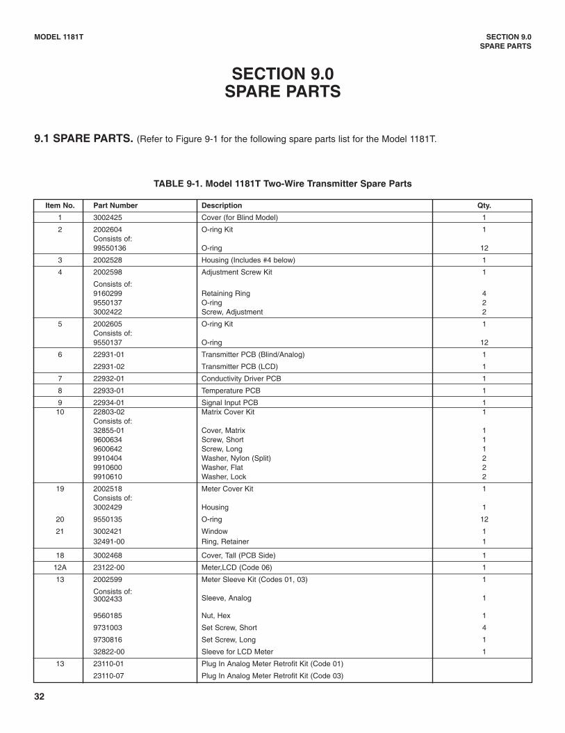
Item No. Part Number Description Qty.
1 3002425 Cover (for Blind Model) 1
2 2002604 O-ring Kit 1Consists of:99550136 O-ring 12
3 2002528 Housing (Includes #4 below) 1
4 2002598 Adjustment Screw Kit 1
Consists of:9160299 Retaining Ring 49550137 O-ring 23002422 Screw, Adjustment 2
5 2002605 O-ring Kit 1Consists of:9550137 O-ring 12
6 22931-01 Transmitter PCB (Blind/Analog) 1
22931-02 Transmitter PCB (LCD) 1
7 22932-01 Conductivity Driver PCB 1
8 22933-01 Temperature PCB 1
9 22934-01 Signal Input PCB 110 22803-02 Matrix Cover Kit 1
Consists of:32855-01 Cover, Matrix 19600634 Screw, Short 19600642 Screw, Long 19910404 Washer, Nylon (Split) 29910600 Washer, Flat 29910610 Washer, Lock 2
19 2002518 Meter Cover Kit 1Consists of:3002429 Housing 1
20 9550135 O-ring 12
21 3002421 Window 132491-00 Ring, Retainer 1
18 3002468 Cover, Tall (PCB Side) 1
12A 23122-00 Meter,LCD (Code 06) 1
13 2002599 Meter Sleeve Kit (Codes 01, 03) 1
Consists of:Sleeve, Analog 13002433
9560185 Nut, Hex 1
9731003 Set Screw, Short 4
9730816 Set Screw, Long 1
32822-00 Sleeve for LCD Meter 1
13 23110-01 Plug In Analog Meter Retrofit Kit (Code 01)
23110-07 Plug In Analog Meter Retrofit Kit (Code 03)
SECTION 9.0SPARE PARTS
9.1 SPARE PARTS. (Refer to Figure 9-1 for the following spare parts list for the Model 1181T.
TABLE 9-1. Model 1181T Two-Wire Transmitter Spare Parts
MODEL 1181T SECTION 9.0SPARE PARTS
33
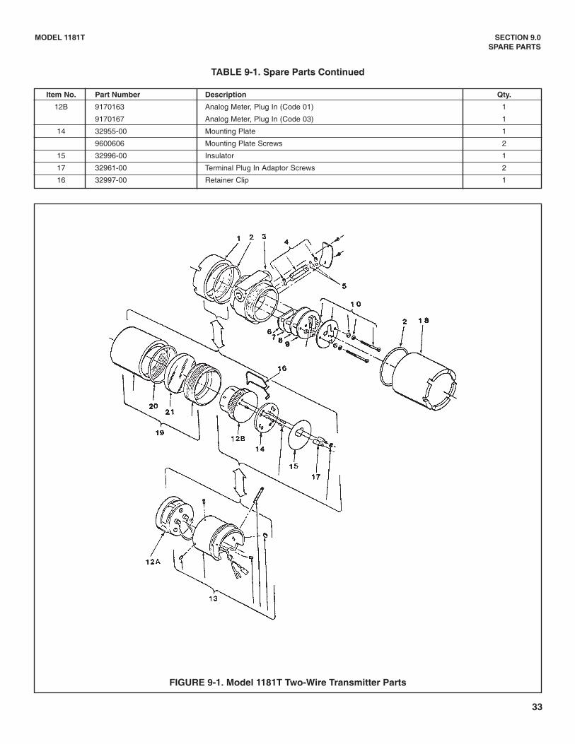
Item No. Part Number Description Qty.
12B 9170163 Analog Meter, Plug In (Code 01) 1
9170167 Analog Meter, Plug In (Code 03) 1
14 32955-00 Mounting Plate 1
9600606 Mounting Plate Screws 2
15 32996-00 Insulator 1
17 32961-00 Terminal Plug In Adaptor Screws 2
16 32997-00 Retainer Clip 1
MODEL 1181T SECTION 9.0SPARE PARTS
TABLE 9-1. Spare Parts Continued
FIGURE 9-1. Model 1181T Two-Wire Transmitter Parts
34
MODEL 1181T SECTION 10.0RETURN OF MATERIAL
SECTION 10.0RETURN OF MATERIAL
10.1 GENERAL
To expedite the repair and return of instruments, propercommunication between the customer and the factory isimportant. Before returning a product for repair, call 1-949-757-8500 for a Return Materials Authorization(RMA) number.
10.2 WARRANTY REPAIRThe following is the procedure for returning products stillunder warranty.
1. Contact the factory for authorization.
2. To verify warranty, supply the factory sales ordernumber or the original purchase order number. In thecase of individual parts or sub-assemblies, the serialnumber on the mother unit must be supplied.
3. Carefully package the materials and enclose your“Letter of Transmittal”. If possible, pack the materialsin the same manner as it was received.
4. Send the package prepaid to:
Rosemount Analytical Inc., Uniloc Division2400 Barranca ParkwayIrvine, CA 92606
Attn: Factory Repair
Mark the package:
Returned for Repair RMA No. _______________
Model No. ______________
10.3 NON WARRANTY REPAIR1. Contact the factory for authorization.
2. Carefully package the materials and enclose your“Letter of Transmittal”. Include a purchase ordernumber and make sure to include the name and tele-phone number of the right individual to be contactedshould additional information be needed.
4. Do Step 4 of Section 10.2.
NOTEConsult the factory for additional infor-mation regarding service or repair.

WARRANTYSeller warrants that the firmware will execute the programming instructions provided by Seller, and that the Goods manufacturedor Services provided by Seller will be free from defects in materials or workmanship under normal use and care until the expira-tion of the applicable warranty period. Goods are warranted for twelve (12) months from the date of initial installation or eighteen(18) months from the date of shipment by Seller, whichever period expires first. Consumables, such as glass electrodes,membranes, liquid junctions, electrolyte, o-rings, catalytic beads, etc., and Services are warranted for a period of 90days from the date of shipment or provision. Products purchased by Seller from a third party for resale to Buyer ("Resale Products") shall carry only the warranty extended bythe original manufacturer. Buyer agrees that Seller has no liability for Resale Products beyond making a reasonable commercialeffort to arrange for procurement and shipping of the Resale Products. If Buyer discovers any warranty defects and notifies Seller thereof in writing during the applicable warranty period, Seller shall, atits option, promptly correct any errors that are found by Seller in the firmware or Services, or repair or replace F.O.B. point of man-ufacture that portion of the Goods or firmware found by Seller to be defective, or refund the purchase price of the defective por-tion of the Goods/Services. All replacements or repairs necessitated by inadequate maintenance, normal wear and usage, unsuitable power sources, unsuit-able environmental conditions, accident, misuse, improper installation, modification, repair, storage or handling, or any othercause not the fault of Seller are not covered by this limited warranty, and shall be at Buyer's expense. Seller shall not be obligat-ed to pay any costs or charges incurred by Buyer or any other party except as may be agreed upon in writing in advance by anauthorized Seller representative. All costs of dismantling, reinstallation and freight and the time and expenses of Seller's person-nel for site travel and diagnosis under this warranty clause shall be borne by Buyer unless accepted in writing by Seller. Goods repaired and parts replaced during the warranty period shall be in warranty for the remainder of the original warranty peri-od or ninety (90) days, whichever is longer. This limited warranty is the only warranty made by Seller and can be amended onlyin a writing signed by an authorized representative of Seller. Except as otherwise expressly provided in the Agreement, THEREARE NO REPRESENTATIONS OR WARRANTIES OF ANY KIND, EXPRESS OR IMPLIED, AS TO MERCHANTABILITY, FIT-NESS FOR PARTICULAR PURPOSE, OR ANY OTHER MATTER WITH RESPECT TO ANY OF THE GOODS OR SERVICES.
RETURN OF MATERIAL
Material returned for repair, whether in or out of warranty, should be shipped prepaid to:
Emerson Process ManagementLiquid Division
2400 Barranca ParkwayIrvine, CA 92606
The shipping container should be marked:Return for RepairModel _______________________________
The returned material should be accompanied by a letter of transmittal which should include the following information (make acopy of the "Return of Materials Request" found on the last page of the Manual and provide the following thereon):
1. Location type of service, and length of time of service of the device.2. Description of the faulty operation of the device and the circumstances of the failure.3. Name and telephone number of the person to contact if there are questions about the returned material.4. Statement as to whether warranty or non-warranty service is requested.5. Complete shipping instructions for return of the material.
Adherence to these procedures will expedite handling of the returned material and will prevent unnecessary additional chargesfor inspection and testing to determine the problem with the device.
If the material is returned for out-of-warranty repairs, a purchase order for repairs should be enclosed.
Credit Cards for U.S. Purchases Only.
The right people,the right answers,right now.
ON-LINE ORDERING NOW AVAILABLE ON OUR WEB SITEhttp://www.raihome.com
Emerson Process ManagementLiquid Division2400 Barranca ParkwayIrvine, CA 92606 USATel: (949) 757-8500Fax: (949) 474-7250
http://www.raihome.com
© Rosemount Analytical Inc. 2003