Embed Size (px)
Citation preview

Service ExperienceMAN B&W Two-stroke Diesel Engines

Two-Stroke Service Experience
Introduction .................................................................................................... 5
Piston Ring Development ................................................................................ 5
Cold Corrosion Control .................................................................................... 7
Cylinder Lubrication – The Near Future .......................................................... 11
Crosshead Bearing Design for S and G-Type Engines (Mark 9 & 10) ............... 13
Main Bearings ............................................................................................... 15
Engine and Ship Acceleration Issues ............................................................. 16
Variable Exhaust Valve Timing on ME-B Engines ............................................ 20
ME-B9.3 Inductive Sensors ........................................................................... 22
G & S50ME-B9.3 Timing Unit Piston Design Modification ............................... 23
Multi-Purpose Controller (MPC) Quality Issue ................................................. 23
System Oil Cleanliness on ME-C/ME-B Engines ............................................. 26
Tier III Service and Test Experience ................................................................ 28
ME-GI Service Experience ............................................................................. 31
Conclusion .................................................................................................... 33

Two-Stroke Service Experience 5
Introduction
A high number of G-type and S-type
engines of the latest generation have
entered service successfully. These
engines are generally characterised by
Tier II compliance, heavily derated lay-
outs and performance with main focus
on part and low-load fuel optimisa-
tion. Very close to 100% of these en-
gines are of the electronically controlled
ME-C and ME-B types.
This paper describes cylinder condition
issues, including the latest piston ring
development, and the development
within cylinder lubrication, including an
introduction of the automated cylinder
oil mixing (ACOM) system. The ACOM
system needs cylinder oils with a BN
higher than 100 to achieve optimum
work performance. Furthermore, the
developments of crosshead and main
bearings are described.
The acceleration issues for ships with
heavily derated engines fulfilling the en-
ergy efficiency design index (EEDI) rules
have been solved by introducing larger
propeller light running margins as well
as implementation of dynamically opti-
mised running modes (via the so-called
Dynamic Limiter Function function). An
example of such a running mode is giv-
en for a large VLOC.
In relation to electronically controlled
engines, the optimisation of the ME-B
engine’s timing units is shown. Quality
issues for the multi-purpose controllers
(MPCs) are also dealt with and, further-
more, system oil cleanliness and its re-
lation to control valve wear is outlined.
The service experience of Tier III tech-
nology, including both EGR and SCR
solutions, is described and, last but not
least, the first service experience with
ME-GI dual fuel engines is presented.
Piston Ring Development
The increased cylinder pressures and
longer process time on the latest gener-
ation of super-long-stroke S and G-type
engines has called for further develop-
ment of pistons and piston rings. Fig. 1
shows an example of this development
in a comparison of the piston and pis-
ton ring pack for an S70ME-C8.2 and a
G70ME-C9.2. On the G70 engine, the
distance from the piston top to the up-
permost piston ring, the piston topland,
has been increased in order to protect
the cylinder liner against sulphuric gas-
ses at high pressures.
Furthermore, the G70 engine is
equipped with a three-ring gastight ring
pack limiting the amount of hot com-
bustion gasses penetrating the piston
rings. This will limit the heat impact on
the piston ring pack.
S70ME-C8.2
App. mass 666 kg
G70ME-C9.2
App. mass 740 kg
Fig. 1: Comparison of piston and ring pack for an S70ME-C8.2 and a G70ME-C9.2 with increased piston topland
Two-Stroke Service Experience6
Fig. 2 shows a brief summary of the de-
velopment of our piston rings on MAN
B&W two-stroke engines over approxi-
mately three decades. The MC engine
era started with adaptation of the rather
simple four-ring “oblique-cut ring pack”.
This simple ring pack was exhausted
when the maximum pressures reached
approximately 140 bar. We therefore
developed the highly successful four-
ring pack with a CPR top piston ring.
However, this ring pack needed further
development when the 9.2 Tier II en-
gines with maximum pressures above
180 bar became the standard.
To cope with this development, we de-
signed the gas-tight three-ring pack.
Fig. 3 shows the very good service re-
sults obtained with the three-ring pack
on a 6G70ME-C9.2. Clean piston ring
lands and low piston ring wear can be
seen.
Fig. 3: Service experience with gas-tight 3-ring pack after 4,446 hours
1st ring
2nd ring
CPR
CPR
gas-tight
4 CPR ringspmax. 140 bar
3 CPR/gas-tight ringspmax. 185 bar
3rd ring
4th ring
Development
4 oblique-cut ringspmax. 120 bar
Fig. 2: Piston ring development
Cylinder 1 Cylinder 2
Cylinder 3 Cylinder 4
Two-Stroke Service Experience 7
Cold Corrosion Control
In recent years, cold corrosion has
been high on the agenda at MAN Die-
sel & Turbo, working with fuel optimised
two-stroke engines. A number of fac-
tors have been identified, which influ-
ence the degree of cold corrosion on
two-stroke MAN B&W engines:
� amount of derating
� low and part load optimisation
� two-stroke Miller timing
� maximum pressure level
� waste heat recovery (WHR) applica-
tion
� scavenge air temperature.
If the combustion chamber design is
unchanged, derating an engine will
reduce the cylinder liner temperature
compared to the fully-rated engine.
Lately, this has been counteracted by
the introduction of the rating depend-
ent liner (RDL) design. This will be ex-
plained in detail later in this section.
Low and part load optimisation in-
creases the cylinder pressure levels at
lower loads, which also contributes to
increased cold corrosion.
Other important factors are two-stroke
Miller timing, increase of maximum
pressures in general and application of
waste heat recovery (WHR) systems,
especially when WHR is not operated
on engines designed with this system.
The temperature of the scavenge air is
a very important factor for the extent
of cold corrosion. In order to limit the
amount of water vapour entering the
combustion chamber, the scavenge
air temperature must always be kept
as low as possible. This is also optimal
with respect to the fuel oil consump-
tion. We therefore emphasise that the
freshwater temperature setpoint must
always be 10°C. This ensures the low-
est possible scavenge air temperature
at all times, although it depends on the
actual sea water temperature.
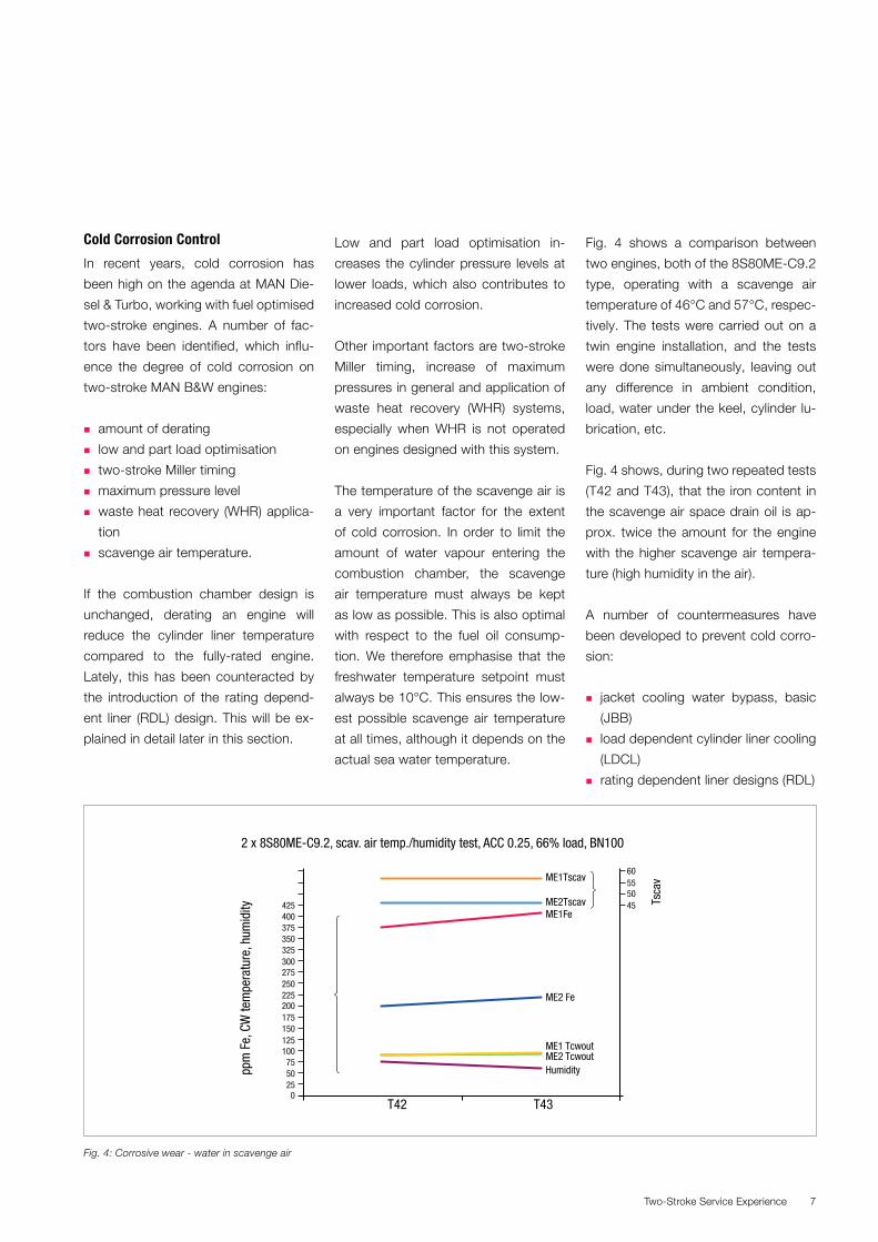
Fig. 4 shows a comparison between
two engines, both of the 8S80ME-C9.2
type, operating with a scavenge air
temperature of 46°C and 57°C, respec-
tively. The tests were carried out on a
twin engine installation, and the tests
were done simultaneously, leaving out
any difference in ambient condition,
load, water under the keel, cylinder lu-
brication, etc.
Fig. 4 shows, during two repeated tests
(T42 and T43), that the iron content in
the scavenge air space drain oil is ap-
prox. twice the amount for the engine
with the higher scavenge air tempera-
ture (high humidity in the air).
A number of countermeasures have
been developed to prevent cold corro-
sion:
� jacket cooling water bypass, basic
(JBB)
� load dependent cylinder liner cooling
(LDCL)
� rating dependent liner designs (RDL)
ME2 Fe
ME1 Tcwout
Humidity
T42
ppm
Fe,
CW
tem
pera
ture
, hum
idity Ts
cav
T43
ME2 Tcwout
ME1Tscav
ME2TscavME1Fe
2 x 8S80ME-C9.2, scav. air temp./humidity test, ACC 0.25, 66% load, BN100
025
45505560
5075
100125150175200225250275300325350375400425
Fig. 4: Corrosive wear - water in scavenge air
Two-Stroke Service Experience8
The cylinder oil feed rates have been
reduced by introducing these counter-
measures.
A very important step in the control of
cold corrosion, while also maintaining
reasonable cylinder oil feed rates, has
been the introduction of the BN100 cyl-
inder oil. The BN100 cylinder oil, which
is now the standard on newer MAN
B&W two-stroke engines, gives bet-
ter than “BN-proportional” protection
against cold corrosion compared to a
BN70 cylinder oil.
However, the development in this area
does not stop here – we are now test-
ing a BN140 cylinder oil in combination
with a new cylinder oil lubrication sys-
tem, where a variable BN level is ap-
plied for fuels (liquid or gaseous) with
large variations in sulphur content. We
have denoted the system automated
cylinder oil mixing (ACOM).
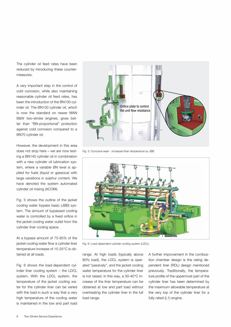
Fig. 5 shows the outline of the jacket
cooling water bypass basic (JBB) sys-
tem. The amount of bypassed cooling
water is controlled by a fixed orifice in
the jacket cooling water outlet from the
cylinder liner cooling space.
At a bypass amount of 75-85% of the
jacket cooling water flow a cylinder liner
temperature increase of 15-25°C is ob-
tained at all loads.
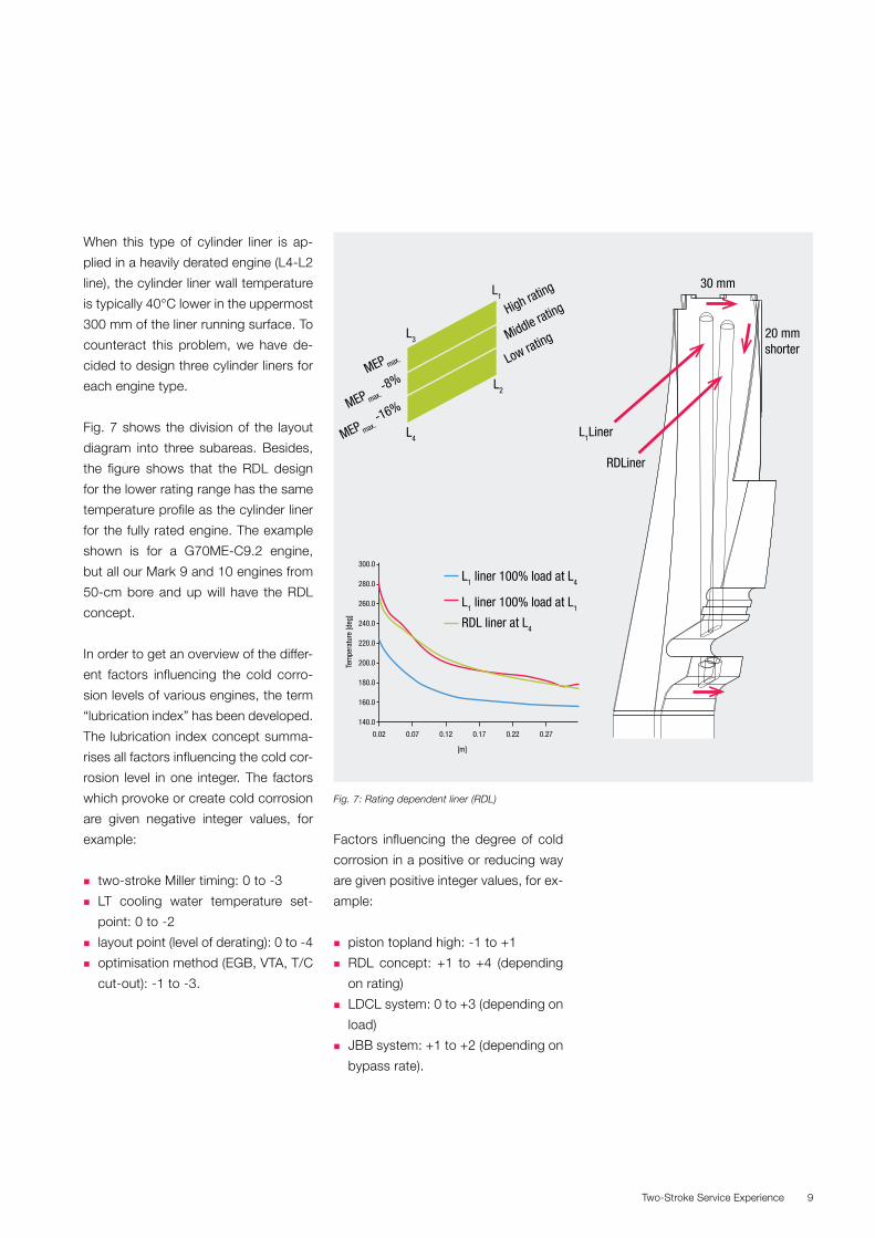
Fig. 6 shows the load-dependent cyl-
inder liner cooling system – the LDCL
system. With the LDCL system, the
temperature of the jacket cooling wa-
ter for the cylinder liner can be varied
with the load in such a way that a very
high temperature of the cooling water
is maintained in the low and part load
range. At high loads (typically above
80% load), the LDCL system is oper-
ated “passively”, and the jacket cooling
water temperature for the cylinder liner
is not raised. In this way, a 30-40°C in-
crease of the liner temperature can be
obtained at low and part load without
overheating the cylinder liner in the full
load range.
A further improvement in the combus-
tion chamber design is the rating de-
pendent liner (RDL) design mentioned
previously. Traditionally, the tempera-
ture profile of the uppermost part of the
cylinder liner has been determined by
the maximum allowable temperature at
the very top of the cylinder liner for a
fully rated (L1) engine.
Fig. 5: Corrosive wear - increased liner temperature by JBB
Orifice plate to control the unit flow resistance
Fig. 6: Load-dependent cylinder cooling system (LDCL)
Two-Stroke Service Experience 9
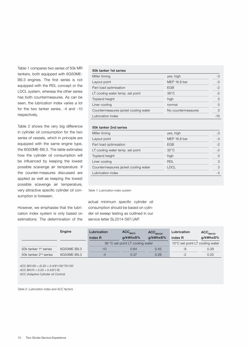
When this type of cylinder liner is ap-
plied in a heavily derated engine (L4-L2
line), the cylinder liner wall temperature
is typically 40°C lower in the uppermost
300 mm of the liner running surface. To
counteract this problem, we have de-
cided to design three cylinder liners for
each engine type.
Fig. 7 shows the division of the layout
diagram into three subareas. Besides,
the figure shows that the RDL design
for the lower rating range has the same
temperature profile as the cylinder liner
for the fully rated engine. The example
shown is for a G70ME-C9.2 engine,
but all our Mark 9 and 10 engines from
50-cm bore and up will have the RDL
concept.
In order to get an overview of the differ-
ent factors influencing the cold corro-
sion levels of various engines, the term
“lubrication index” has been developed.
The lubrication index concept summa-
rises all factors influencing the cold cor-
rosion level in one integer. The factors
which provoke or create cold corrosion
are given negative integer values, for
example:
� two-stroke Miller timing: 0 to -3
� LT cooling water temperature set-
point: 0 to -2
� layout point (level of derating): 0 to -4
� optimisation method (EGB, VTA, T/C
cut-out): -1 to -3.
Factors influencing the degree of cold
corrosion in a positive or reducing way
are given positive integer values, for ex-
ample:
� piston topland high: -1 to +1
� RDL concept: +1 to +4 (depending
on rating)
� LDCL system: 0 to +3 (depending on
load)
� JBB system: +1 to +2 (depending on
bypass rate).
L3
L1
L4
L2
MEP max.
MEP max. -8%
MEP max. -16%
High rating
Middle rating
Low rating
300.0
280.0
260.0
240.0
220.0
Tem
pera
ture
[deg
]
200.0
180.0
160.0
140.0
0.02 0.07 0.12 0.17 0.22 0.27
[m]
L1 liner 100% load at L4
L1 liner 100% load at L1
RDL liner at L4
L1Liner
30 mm
20 mmshorter
RDLiner
Fig. 7: Rating dependent liner (RDL)
Two-Stroke Service Experience10
Table 1 compares two series of 50k MR
tankers, both equipped with 6G50ME-
B9.3 engines. The first series is not
equipped with the RDL concept or the
LDCL system, whereas the other series
has both countermeasures. As can be
seen, the lubrication index varies a lot
for the two tanker series, -4 and -10
respectively.
Table 2 shows the very big difference
in cylinder oil consumption for the two
series of vessels, which in principle are
equipped with the same engine type,
the 6G50ME-B9.3. The table estimates
how the cylinder oil consumption will
be influenced by keeping the lowest
possible scavenge air temperature. If
the counter-measures discussed are
applied as well as keeping the lowest
possible scavenge air temperature,
very attractive specific cylinder oil con-
sumption is foreseen.
However, we emphasise that the lubri-
cation index system is only based on
estimations. The determination of the
actual minimum specific cylinder oil
consumption should be based on cylin-
der oil sweep testing as outlined in our
service letter SL2014-587/JAP.
Engine Lubrication
index R
ACCBN70
g/kWhxS%
ACCBN100
g/kWhxS%
Lubrication
index R
ACCBN100
g/kWhxS%
36 °C set point LT cooling water 10°C set point LT cooling water
50k tanker 1st series 6G50ME-B9.3 -10 0.64 0.45 -8 0.39
50k tanker 2nd series 6G50ME-B9.3 -4 0.37 0.26 -2 0.20
ACC BN100 = (0.20 + 0.4/9*(-R))*70/100 ACC BN70 = 0.20 + 0.4/9*(-R) ACC (Adaptive Cylinder oil Control)
Table 2: Lubrication index and ACC factors
50k tanker 1st series
Miller timing yes, high -3
Layout point MEP 16.8 bar -3
Part load optimisation EGB -2
LT cooling water temp. set point 36°C -2
Topland height high 0
Liner cooling normal 0
Countermeasures jacket cooling water No countermeasures 0
Lubrication index -10
50k tanker 2nd series
Miller timing yes, high -3
Layout point MEP 16.8 bar -3
Part load optimisation EGB -2
LT cooling water temp. set point 32°C -2
Topland height high 0
Liner cooling RDL 3
Countermeasures jacket cooling water LDCL 3
Lubrication index -4
Table 1: Lubrication index system
Two-Stroke Service Experience 11
Cylinder Lubrication – The Near Future
We approach times where the sulphur
equivalent of the fuel (liquid or gaseous)
will vary to a great extent. This goes for
conventional diesel engines operating in
and out of SECA areas and for ME-GI/
LGI engines also operating in and out
of SECA areas with varying amounts of
sulphur content in the pilot fuel oil.
MAN Diesel & Turbo develops a sys-
tem, which will be integrated in the ME
electronic control system (ME-ECS), for
mixing of two approved cylinder oils
with different BN numbers, i.e. a low-
BN cylinder oil is mixed with a high-BN
cylinder oil.
We denote the system automated cyl-
inder oil mixing (ACOM), see Fig. 8.
The ACOM unit consists of three small
tanks: one for low-BN cylinder oil, one
for high-BN cylinder oil and one for the
mixed optimal BN cylinder oil, see Fig.
9. When an ACOM unit is installed on
a vessel, the normal day tank for cyl-
inder oil can be avoided. The ACOM
unit takes cylinder oil directly from the
cylinder oil storage tanks. The ACOM
unit seen in Fig. 9 is a prototype version
without ME-ECS integrated control.
When applying the ACOM unit, it is es-
sential that the optimal cylinder oil feed
rate factor (ACC factor) is known. This
knowledge is gained by making a cylin-
der oil sweep test.
Mix a high BN and a BN25 cylinder oil “step-less”
Blending range from BN25 to BN100 or higher
Ensure optimal BN at minimum feed rate at anytime
Significantly reduced cylinder oil dosages
Minimum feed rate result in increased lubricating efficiency
Always correct viscosity and optimal detergency
Quick change between BN levels when changing fuel (in/out of SECA)
HighBN
LowBN
ACOMmixing unit optimal BN
Fig. 8: Automated cylinder oil mixing (ACOM)
00 20 40 60 80 100 130
20
40
60
80
100
120
ACOM
del
iver
ed c
alc.
BN
ACOM ordered BN
ACOM: ordered vs. delivered calc. BN
Target line
55 BN ordered
75 BN ordered
35 BN ordered
Fig. 9: Automated cylinder oil mixing (ACOM) unit

Two-Stroke Service Experience12
When the ACC factor is known, it is
keyed in on the main operating panel
(MOP) on the cylinder oil control screen.
The sulphur content of the fuel for ME
engines is also keyed in on the MOP or,
if it is dual fuel ME-GI/LGI engines, the
sulphur content of the two fuels used.
The ACOM software will then calculate
the lowest possible optimum cylinder
oil feed rate.
Fig. 10 shows the variations in cylinder
oil BN for different equivalent fuel sul-
phur contents from 0% to 3.5%. Curves
for various ACC factors are shown, and
it can be seen that it will often be pos-
sible to apply the minimum feed rate of
0.6 g/kWh.
In the example in Fig. 10, BN25 and
BN140 cylinder oils are mixed. MAN
Diesel & Turbo believes that cylinder
oils with a BN higher than 100 is neces-
sary to be able to take full advantage of
the ACOM system. Tests are presently
being conducted with various brands of
BN140 cylinder oil.
The reason for asking for a further in-
crease of the cylinder oil BN is that
we will have an increased “lubrication
efficiency” with the lowest possible
absolute cylinder oil feed rate. We will
lose the lowest percentage of unused
cylinder oil if we feed the lowest pos-
sible amount of oil into the combustion
chamber. It is equivalent to painting a
wall with a paint brush – if too much
paint is applied on the brush, a high
percentage is lost on the floor.
Table 3 outlines the theoretic cost in-
crease when the BN number of the cyl-
inder oil is raised. As shown, a 100%
increase of BN (from BN70 to BN140)
can be obtained for a cost increase of
19-32% depending on the ratio of cost
between the additive package and the
base oil.
0
0 0.5 1 1.5 2 2.5 3 3.5
20
40
60
80
100
120
140
160
Automated Cylinder Oil Mixing (ACOM)Mixing BN25 and BN140
ACOM
BN
Sulphur %
Min. oil
0.6 g/kw
h at A
CC 0.36 g/kw
h x 5%
Min. oil 0.6 g/kw
h at ACC 0.31 g/kwh x 5
%
Min. oil 0.6 g/kwh at ACC 0.23 g/kwh x 5%
Increase of feed rate
Fig. 10: Automated cylinder oil mixing (ACOM)
Additive (BN300) cost = 2 x base
oil cost
BN70: 100%
BN100: 108%
BN140: 119%
Additive (BN300) cost = 3 x base
oil cost
BN70: 100%
BN100: 114%
BN140: 132%
Table 3: Cost of high-BN cylinder oils
Two-Stroke Service Experience 13
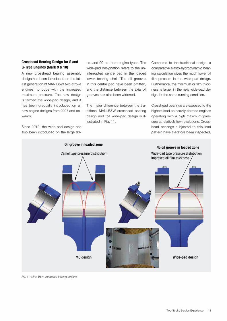
Crosshead Bearing Design for S and G-Type Engines (Mark 9 & 10)
A new crosshead bearing assembly
design has been introduced on the lat-
est generation of MAN B&W two-stroke
engines, to cope with the increased
maximum pressure. The new design
is termed the wide-pad design, and it
has been gradually introduced on all
new engine designs from 2007 and on-
wards.
Since 2012, the wide-pad design has
also been introduced on the large 80-
cm and 90-cm bore engine types. The
wide-pad designation refers to the un-
interrupted centre pad in the loaded
lower bearing shell. The oil grooves
in this centre pad have been omitted,
and the distance between the axial oil
grooves has also been widened.
The major difference between the tra-
ditional MAN B&W crosshead bearing
design and the wide-pad design is il-
lustrated in Fig. 11.
Compared to the traditional design, a
comparative elasto-hydrodynamic bear-
ing calculation gives the much lower oil
film pressure in the wide-pad design.
Furthermore, the minimum oil film thick-
ness is larger in the new wide-pad de-
sign for the same running condition.
Crosshead bearings are exposed to the
highest load on heavily derated engines
operating with a high maximum pres-
sure at relatively low revolutions. Cross-
head bearings subjected to this load
pattern have therefore been inspected.
Oil groove in loaded zone
MC design Wide-pad design
No oil groove in loaded zone
Camel type pressure distribution Wide-pad type pressure distributionImproved oil film thickness
Fig. 11: MAN B&W crosshead bearing designs

Two-Stroke Service Experience14
A 7G80ME-C9.2 was first inspected af-
ter sea trial and then again after 6,600
running hours.
Fig. 12 shows the condition after sea
trial, which is very good with well-dis-
tributed bearing load over the entire
bearing shell.
Figs. 13 and 14 show the condition of
the bearings No. 4 and No. 6, respec-
tively, after 6,600 hours of operation.
Good contact can be seen on the cen-
tre pad and far up on the lower side
pads.
Only insignificant local wiping is visible
on the lead overlayer. This is a natural
part of the bearing adaption using re-
distribution of the lead overlayer. This
redistribution of overlayer has occurred
within the first running hours in service.
No indications of micro-cracks or other
abnormalities can be seen.
Fig. 12: 7G80ME-C9.2 – crosshead bearing after sea trial
Fig. 13: 7G80ME-C9.2 – crosshead bearing #4 after 6,619 hours
Fig. 17.14: 7G80ME-C9.2 – crosshead bearing #6 after 6,619 hours
Two-Stroke Service Experience 15
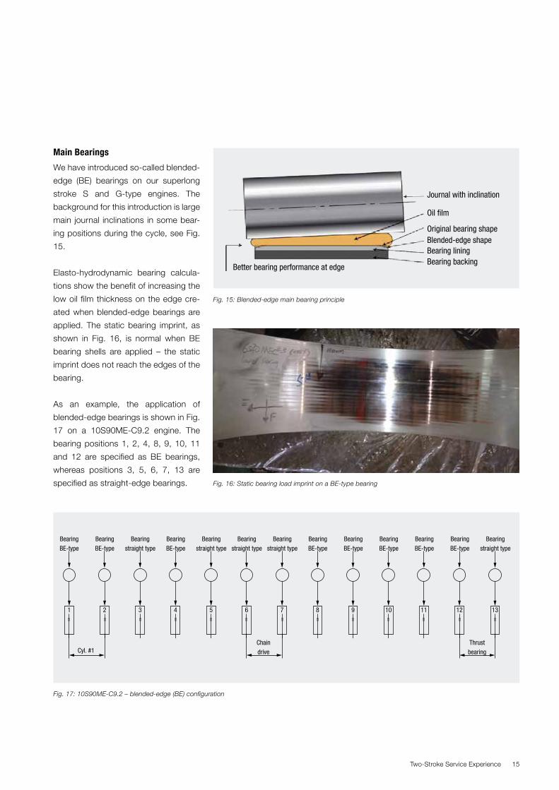
Main Bearings
We have introduced so-called blended-
edge (BE) bearings on our superlong
stroke S and G-type engines. The
background for this introduction is large
main journal inclinations in some bear-
ing positions during the cycle, see Fig.
15.
Elasto-hydrodynamic bearing calcula-
tions show the benefit of increasing the
low oil film thickness on the edge cre-
ated when blended-edge bearings are
applied. The static bearing imprint, as
shown in Fig. 16, is normal when BE
bearing shells are applied – the static
imprint does not reach the edges of the
bearing.
As an example, the application of
blended-edge bearings is shown in Fig.
17 on a 10S90ME-C9.2 engine. The
bearing positions 1, 2, 4, 8, 9, 10, 11
and 12 are specified as BE bearings,
whereas positions 3, 5, 6, 7, 13 are
specified as straight-edge bearings.
Journal with inclination
Better bearing performance at edge
Oil film
Original bearing shapeBlended-edge shapeBearing liningBearing backing
Fig. 15: Blended-edge main bearing principle
Fig. 16: Static bearing load imprint on a BE-type bearing
Fig. 17: 10S90ME-C9.2 – blended-edge (BE) configuration
1
Cyl. #1Chaindrive
Thrustbearing
BearingBE-type
BearingBE-type
Bearingstraight type
Bearingstraight type
Bearingstraight type
Bearingstraight type
Bearingstraight type
BearingBE-type
BearingBE-type
BearingBE-type
BearingBE-type
BearingBE-type
BearingBE-type
2 3 4 5 6 7 8 9 10 11 12 13
Two-Stroke Service Experience16
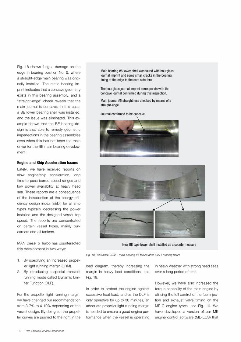
Fig. 18 shows fatigue damage on the
edge in bearing position No. 5, where
a straight-edge main bearing was origi-
nally installed. The static bearing im-
print indicates that a concave geometry
exists in this bearing assembly, and a
“straight-edge” check reveals that the
main journal is concave. In this case,
a BE lower bearing shell was installed,
and the issue was eliminated. This ex-
ample shows that the BE bearing de-
sign is also able to remedy geometric
imperfections in the bearing assemblies
even when this has not been the main
driver for the BE main bearing develop-
ment.
Engine and Ship Acceleration Issues
Lately, we have received reports on
slow engine/ship acceleration, long
time to pass barred speed ranges and
low power availability at heavy head
sea. These reports are a consequence
of the introduction of the energy effi-
ciency design index (EEDI) for all ship
types typically decreasing the power
installed and the designed vessel top
speed. The reports are concentrated
on certain vessel types, mainly bulk
carriers and oil tankers.
MAN Diesel & Turbo has counteracted
this development in two ways:
1. By specifying an increased propel-
ler light running margin (LRM).
2. By introducing a special transient
running mode called Dynamic Lim-
iter Function (DLF).
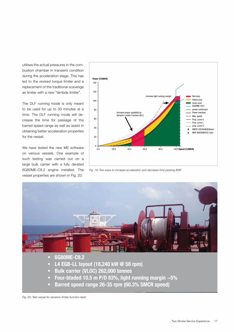
For the propeller light running margin,
we have changed our recommendation
from 3-7% to 4-10% depending on the
vessel design. By doing so, the propel-
ler curves are pushed to the right in the
load diagram, thereby increasing the
margin in heavy load conditions, see
Fig. 19.
In order to protect the engine against
excessive heat load, and as the DLF is
only operative for up to 30 minutes, an
adequate propeller light running margin
is needed to ensure a good engine per-
formance when the vessel is operating
in heavy weather with strong head seas
over a long period of time.
However, we have also increased the
torque capability of the main engine by
utilising the full control of the fuel injec-
tion and exhaust valve timing on the
ME-C engine types, see Fig. 19. We
have developed a version of our ME
engine control software (ME-ECS) that
Main bearing #5 lower shell was found with hourglass journal imprint and some small cracks in the bearing lining at the edge to the cam side fore. The hourglass journal imprint corresponds with the concave journal confirmed during this inspection.
Main journal #5 straightness checked by means of a straight-edge.
Journal confirmed to be concave.
New BE type lower shell installed as a countermeasure
Fig. 18: 10S90ME.C9.2 – main bearing #5 failure after 5,271 running hours
Two-Stroke Service Experience 17
utilises the actual pressures in the com-
bustion chamber in transient condition
during the acceleration stage. This has
led to the revised torque limiter and a
replacement of the traditional scavenge
air limiter with a new “lambda limiter”.
The DLF running mode is only meant
to be used for up to 30 minutes at a
time. The DLF running mode will de-
crease the time for passage of the
barred speed range as well as assist in
obtaining better acceleration properties
for the vessel.
We have tested the new ME software
on various vessels. One example of
such testing was carried out on a
large bulk carrier with a fully derated
6G80ME-C9.2 engine installed. The
vessel properties are shown in Fig. 20.
Fig. 19: Two ways to increase acceleration and decrease time passing BSR
00.0 20.0 40.0 60.0 80.0
Red areaIncrease light running margin
Increase torque capability byDynamic Limiter Function (DLF)
Yellow areaGreen area6G80ME-C9.2
power continuousPower overload
Max. speedProp. curve SProp. curve Lprop. curve O
SMCR 18240kW@58rpmMOP [email protected]
100.0 Speed [%SMCR]
Power [%SMCR]
20
40
60
80
100
120
140
6G80ME-C9.2 L4 EGB-LL layout (18,240 kW @ 58 rpm) Bulk carrier (VLOC) 262,000 tonnes Four-bladed 10.5 m P/D 83%, light running margin ~5% Barred speed range 26-35 rpm (60.3% SMCR speed)
Fig. 20: Test vessel for dynamic limiter function tests
Two-Stroke Service Experience18
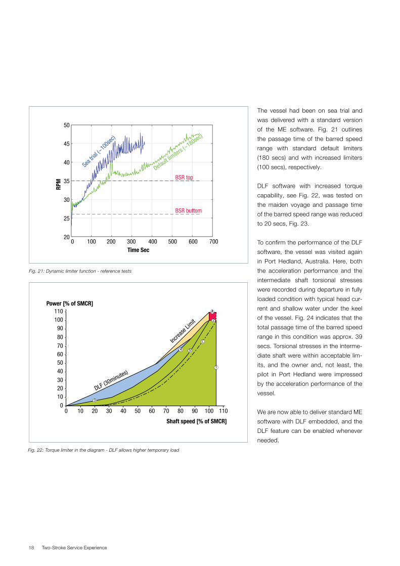
The vessel had been on sea trial and
was delivered with a standard version
of the ME software. Fig. 21 outlines
the passage time of the barred speed
range with standard default limiters
(180 secs) and with increased limiters
(100 secs), respectively.
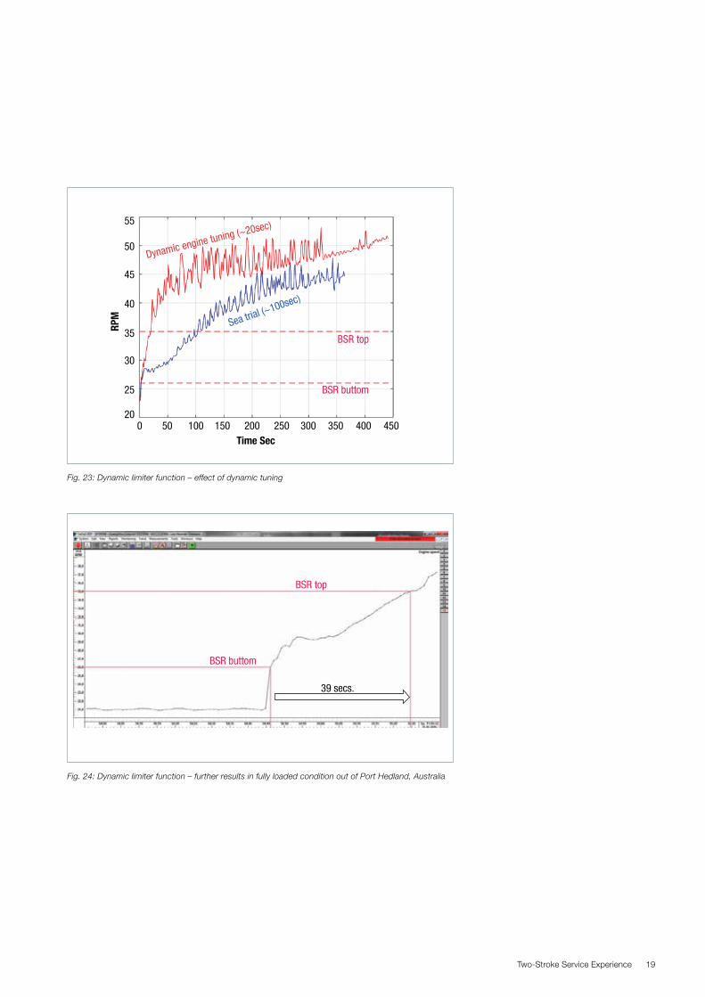
DLF software with increased torque
capability, see Fig. 22, was tested on
the maiden voyage and passage time
of the barred speed range was reduced
to 20 secs, Fig. 23.
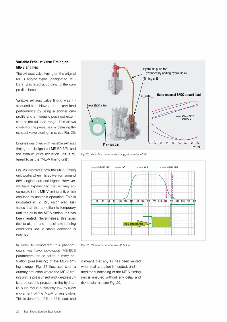
To confirm the performance of the DLF
software, the vessel was visited again
in Port Hedland, Australia. Here, both
the acceleration performance and the
intermediate shaft torsional stresses
were recorded during departure in fully
loaded condition with typical head cur-
rent and shallow water under the keel
of the vessel. Fig. 24 indicates that the
total passage time of the barred speed
range in this condition was approx. 39
secs. Torsional stresses in the interme-
diate shaft were within acceptable lim-
its, and the owner and, not least, the
pilot in Port Hedland were impressed
by the acceleration performance of the
vessel.
We are now able to deliver standard ME
software with DLF embedded, and the
DLF feature can be enabled whenever
needed.
Fig. 21: Dynamic limiter function - reference tests
Fig. 22: Torque limiter in the diagram - DLF allows higher temporary load
Sea tri
al (~
100s
ec)
Default limiters (
~180sec)
BSR top
BSR buttom
50
45
40
35
RPM
30
25
200 100 200 300
Time Sec400 500 600 700
0102030
4050607080
90100110
0 10 20 30 40 50 60 70 80 90 100
Shaft speed [% of SMCR]
Power [% of SMCR]
110
A
2
L
S4
1
3
DLF (30minutes)
Increa
se Li
mit
Two-Stroke Service Experience 19
Fig. 23: Dynamic limiter function – effect of dynamic tuning
Fig. 24: Dynamic limiter function – further results in fully loaded condition out of Port Hedland, Australia
50
55
45
40
35RPM
30
25
200 50 100 150
Time Sec200 250 300 350 400 450
Dynamic engine tuning (~20sec)
Sea trial (~100sec)
BSR top
BSR buttom
39 secs.
BSR top
BSR buttom
Two-Stroke Service Experience20
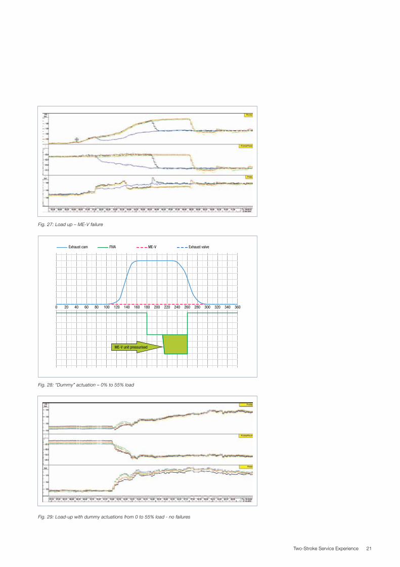
Variable Exhaust Valve Timing on ME-B Engines
The exhaust valve timing on the original
ME-B engine types (designated ME-
B9.2) was fixed according to the cam
profile chosen.
Variable exhaust valve timing was in-
troduced to achieve a better part-load
performance by using a shorter cam
profile and a hydraulic push rod exten-
sion at the full load range. This allows
control of the pressures by delaying the
exhaust valve closing time, see Fig. 25.
Engines designed with variable exhaust
timing are designated ME-B9.3/5, and
the exhaust valve actuation unit is re-
ferred to as the “ME-V timing unit”.
Fig. 26 illustrates how the ME-V timing
unit works when it is active from around
55% engine load and higher. However,
we have experienced that air may ac-
cumulate in the ME-V timing unit, which
can lead to unstable operation. This is
illustrated in Fig. 27, which also illus-
trates that this condition is temporary
until the air in the ME-V timing unit has
been vented. Nevertheless, this gives
rise to alarms and undesirable running
conditions until a stable condition is
reached.
In order to counteract this phenom-
enon, we have developed ME-ECS
parameters for so-called dummy ac-
tuation (pressurising) of the ME-V tim-
ing plunger. Fig. 28 illustrates such a
dummy actuation where the ME-V tim-
ing unit is pressurised and de-pressur-
ised before the pressure in the hydrau-
lic push rod is sufficiently low to allow
movement of the ME-V timing piston.
This is done from 0% to 55% load, and
it means that any air has been vented
when real actuation is needed, and im-
mediate functioning of the ME-V timing
unit is ensured without any delay and
risk of alarms, see Fig. 29.
Hydraulic push rod…...extended by adding hydraulic oil
Timing unit
Previous cam
New short cam
Gain: reduced SFOC at part load
20 30 40 50 60 70 80 90 100
Without ME-VWith ME-V
pmax and pcomp
Load [%]
Fig. 25: Variable exhaust valve timing principle for ME-B
Fig. 26: “Normal” control above 55 % load
0 20 40 60 80 100 120 140 160 180 200 220 240 260 280 300 320 340 360
Exhaust cam FIVA ME-V Exhaust valve
ME-V unit pressurised
Two-Stroke Service Experience 21
Fig. 27: Load up – ME-V failure
Fig. 29: Load-up with dummy actuations from 0 to 55% load - no failures
Fig. 28: “Dummy” actuation – 0% to 55% load
0 20 40 60 80 100 120 140 160 180 200 220 240 260 280 300 320 340 360
Exhaust cam FIVA ME-V Exhaust valve
ME-V unit pressurised
Two-Stroke Service Experience22
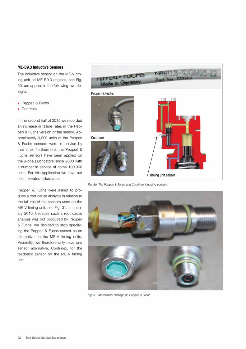
ME-B9.3 Inductive Sensors
The inductive sensor on the ME-V tim-
ing unit on ME-B9.3 engines, see Fig.
30, are applied in the following two de-
signs:
� Pepperl & Fuchs
� Contrinex
In the second half of 2015 we recorded
an increase in failure rates in the Pep-
perl & Fuchs version of the sensor. Ap-
proximately 3,900 units of the Pepperl
& Fuchs sensors were in service by
that time. Furthermore, the Pepperl &
Fuchs sensors have been applied on
the Alpha Lubricators since 2000 with
a number in service of some 100,000
units. For this application we have not
seen elevated failure rates.
Pepperl & Fuchs were asked to pro-
duce a root cause analysis in relation to
the failures of the sensors used on the
ME-V timing unit, see Fig. 31. In Janu-
ary 2016, because such a root cause
analysis was not produced by Pepperl
& Fuchs, we decided to stop specify-
ing the Pepperl & Fuchs sensor as an
alternative on the ME-V timing units.
Presently, we therefore only have one
sensor alternative, Contrinex, for the
feedback sensor on the ME-V timing
unit.
Pepperl & Fuchs
Contrinex
Timing unit sensor
Fig. 30: The Pepperl & Fuchs and Contrinex inductive sensors
Fig. 31: Mechanical damage on Pepperl & Fuchs.
Two-Stroke Service Experience 23
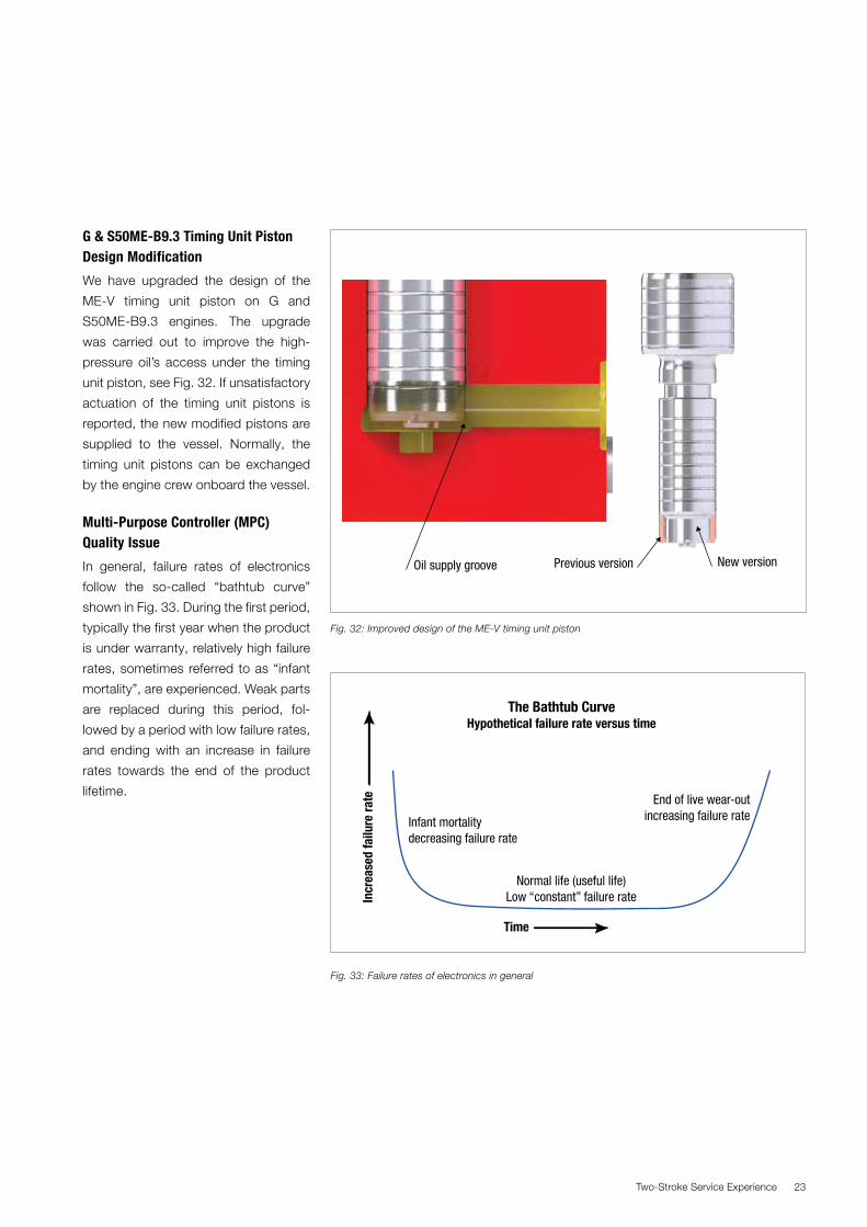
G & S50ME-B9.3 Timing Unit Piston Design Modification
We have upgraded the design of the
ME-V timing unit piston on G and
S50ME-B9.3 engines. The upgrade
was carried out to improve the high-
pressure oil’s access under the timing
unit piston, see Fig. 32. If unsatisfactory
actuation of the timing unit pistons is
reported, the new modified pistons are
supplied to the vessel. Normally, the
timing unit pistons can be exchanged
by the engine crew onboard the vessel.
Multi-Purpose Controller (MPC) Quality Issue
In general, failure rates of electronics
follow the so-called “bathtub curve”
shown in Fig. 33. During the first period,
typically the first year when the product
is under warranty, relatively high failure
rates, sometimes referred to as “infant
mortality”, are experienced. Weak parts
are replaced during this period, fol-
lowed by a period with low failure rates,
and ending with an increase in failure
rates towards the end of the product
lifetime.
Fig. 32: Improved design of the ME-V timing unit piston
Previous version New version Oil supply groove
The Bathtub CurveHypothetical failure rate versus time
Infant mortalitydecreasing failure rate
End of live wear-outincreasing failure rate
Normal life (useful life)Low “constant” failure rate
Time
Incr
ease
d fa
ilure
rate
Fig. 33: Failure rates of electronics in general
Two-Stroke Service Experience24
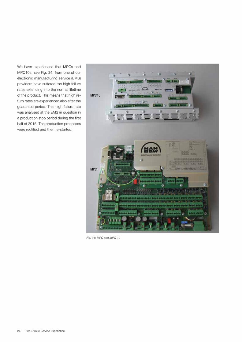
We have experienced that MPCs and
MPC10s, see Fig. 34, from one of our
electronic manufacturing service (EMS)
providers have suffered too high failure
rates extending into the normal lifetime
of the product. This means that high re-
turn rates are experienced also after the
guarantee period. This high failure rate
was analysed at the EMS in question in
a production stop period during the first
half of 2015. The production processes
were rectified and then re-started.
Fig. 34: MPC and MPC-10
MPC10
MPC

Two-Stroke Service Experience 25
During the analysis of the production
processes, flux residues were found on
both the top and on the bottom sides of
the PCBs, see Fig. 35. The presence of
the flux residues may result in electro-
chemical migration (ECM). Investigation
of returned (failing) MPCs and MPC10s
confirmed that when exposed to mois-
ture, electrochemical migration had
taken place. The result is short-circuit-
ing of various components on the PCB,
which again results in malfunctions of
various kinds. Fig. 36 illustrates two ex-
amples of electrochemical migration on
the MPC’s IO board.
We have negotiated an extension of
warranty for MPC/MPC10s from the
EMS involved. This extension includes
two years on top of the standard one-
year warranty. The warranty is valid
independent of who has been the
contract partner with the EMS, and ir-
respective of whether the product has
been purchased through a licensee or
through MAN Diesel & Turbo.
Fig. 35: Flux residues on MPC/MPC10 Fig. 36: Electrochemical migration
MPC 340 CPU (OT0772 )
MPC 350 IO (OT0772)
MPC 0360 IO board (OT0391 )
MPC10 850 IO board
Two-Stroke Service Experience26
System Oil Cleanliness on ME-C/ME-B Engines
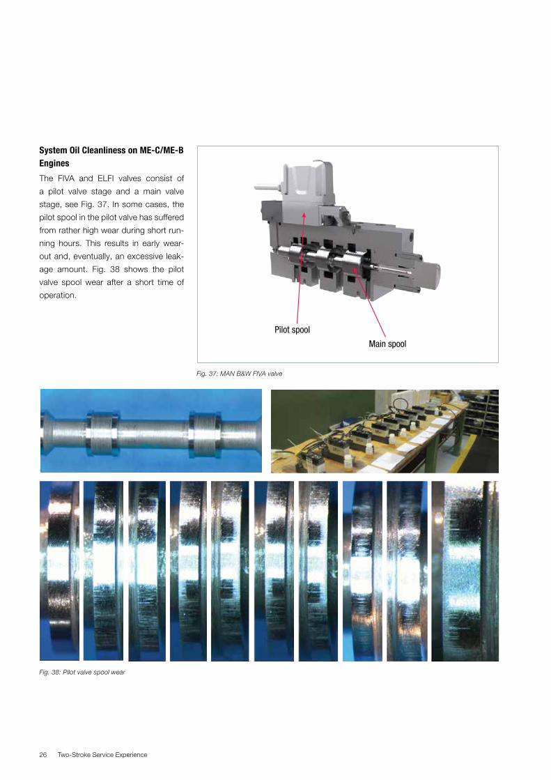
The FIVA and ELFI valves consist of
a pilot valve stage and a main valve
stage, see Fig. 37. In some cases, the
pilot spool in the pilot valve has suffered
from rather high wear during short run-
ning hours. This results in early wear-
out and, eventually, an excessive leak-
age amount. Fig. 38 shows the pilot
valve spool wear after a short time of
operation.
Pilot spool
Main spool
Fig. 37: MAN B&W FIVA valve
Fig. 38: Pilot valve spool wear
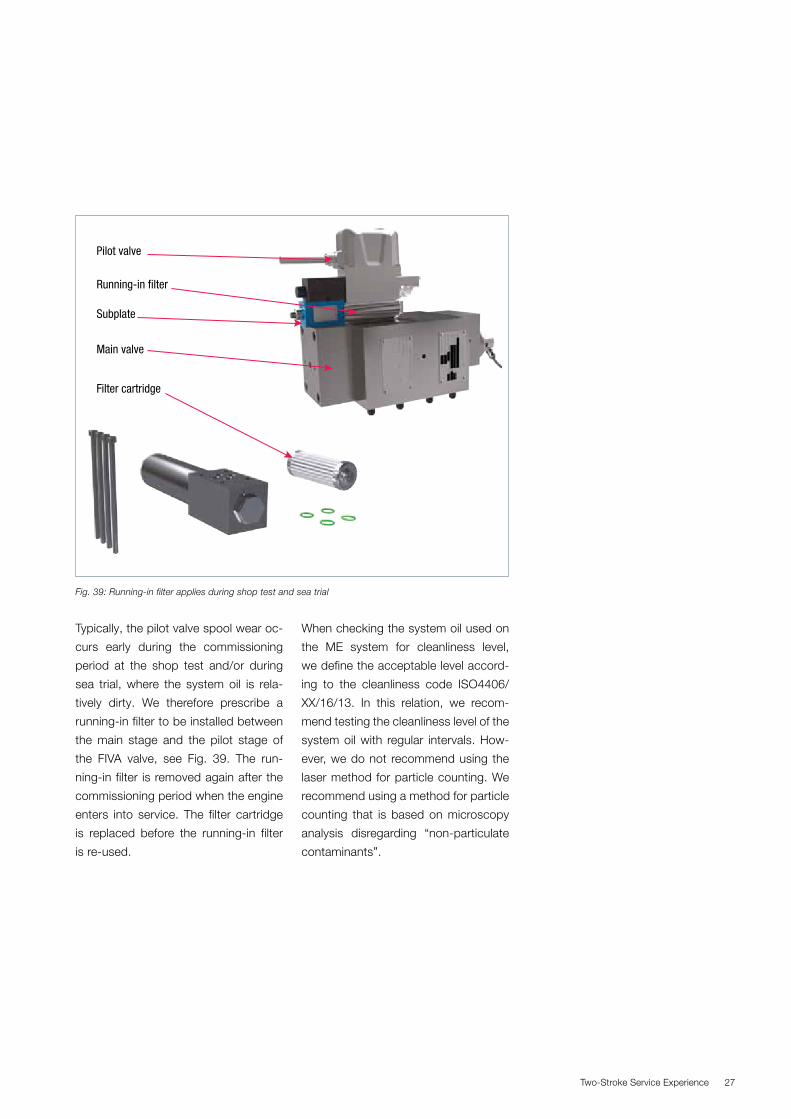
Two-Stroke Service Experience 27
Typically, the pilot valve spool wear oc-
curs early during the commissioning
period at the shop test and/or during
sea trial, where the system oil is rela-
tively dirty. We therefore prescribe a
running-in filter to be installed between
the main stage and the pilot stage of
the FIVA valve, see Fig. 39. The run-
ning-in filter is removed again after the
commissioning period when the engine
enters into service. The filter cartridge
is replaced before the running-in filter
is re-used.
When checking the system oil used on
the ME system for cleanliness level,
we define the acceptable level accord-
ing to the cleanliness code ISO4406/
XX/16/13. In this relation, we recom-
mend testing the cleanliness level of the
system oil with regular intervals. How-
ever, we do not recommend using the
laser method for particle counting. We
recommend using a method for particle
counting that is based on microscopy
analysis disregarding “non-particulate
contaminants”.
Fig. 39: Running-in filter applies during shop test and sea trial
Pilot valve
Main valve
Running-in filter
Subplate
Filter cartridge

Two-Stroke Service Experience28
Tier III Service and Test Experience
Exhaust gas recirculation (EGR) is avail-
able in two different versions. For en-
gines with one turbocharger the cylin-
der bypass solution is used, whereas
T/C cut-out matching is applied for
two or more turbochargers, see Fig.
40. Most service experience has so far
been obtained with the T/C cut-out so-
lution.
In January 2016, some 4,000 running
hours with EGR were obtained, when
counting both prototype testing and
testing in service. Most of these EGR
running hours were performed on high-
sulphur fuel oils with only around 200
hours on low-sulphur fuels.
As of January 2016, the following ves-
sels and engine plants fitted with EGR
(all high-sulphur EGR systems) are in
service:
� Container vessel with 6S80ME-C9
– approx. 3,000 EGR hours on HSFO
(high-sulphur fuel oil).
� Two oil tankers with 6G70ME-C9
– approx. 2 x 500 EGR hours on LSFO
(HSFO EGR system, but running
only on LSFO).
� Oil tanker with 6S60ME-C8
– limited EGR running hours.
Late in 2015, cylinder oil sweep tests
with HSFO were carried out success-
fully onboard the container vessel with
a 6S80ME-C9. These tests indicated a
small cylinder oil consumption penalty
in the Tier III running-mode, see Fig. 41.
In other words, we are able to control
the cold corrosion level in Tier III run-
ning mode.
Cut-out T/C
Cut-out valve
Cut-out valve
Main string
Cylinder bypass
EGR blower
EGR string
Cut-out string
Exhaust receiver
Scavenge air receiver
Cooler
WMCWMC
EGR cooler
EGR unit
Shut-down valve Basic T/CPre-
spray
Cooler spray
Balance pipe
Fig. 40: EGR T/C cut-out matching
Fig 41: Cylinder oil sweep test on 6S80ME-C9 engine with EGR

Two-Stroke Service Experience 29
In order to find ways to lower the initial
cost of EGR, a number of material tests
are ongoing, both on the 6S80ME-C9
and on the vessels with the 6G70ME-
C9 type.
Human errors and the supervision con-
cept of the water treatment system
(WTS) have led to a breakdown of cool-
ers on the 6S80ME-C9, see Fig. 42.
Most likely, the cause is a combination
of chlorides and an extremely low pH-
value. The supervision concept will be
revised for future plants.
We expect that deposits and build-up
of dirt will be much less widespread
when running on LSFO. Initial service
experience seems to confirm this ex-
pectation when comparing a 6G70ME-
C9 on LSFO with a 6S80ME-C9 on
HSFO. Figs. 43 and 44 illustrate the
difference for the EGR mixing chamber.
The water treatment system (WTS)
on the vessel with a 6S80ME-C9 has
reached the maker’s recommended
overhaul time (three years or 6,000 run-
ning hours), and all seals have been
replaced in all separators. A new WTS
strategy is being tested on a 6G70ME-
C9 for the LSFO plants. We call it par-
tial cleaning concept, and this concept
will be tested on a 6G70ME-C9 during
2016. With the present Tier III zones
around USA and Canada, the main
focus will be on LSFO operation with
EGR in the near future.
Fig 42: Damaged and corroded air cooler
Fig. 43: Mixing chamber on a 6G70ME-C9 (LSFO operation) Fig. 44: Mixing chamber on a 6S80ME-C9 (HSFO operation)
Two-Stroke Service Experience30
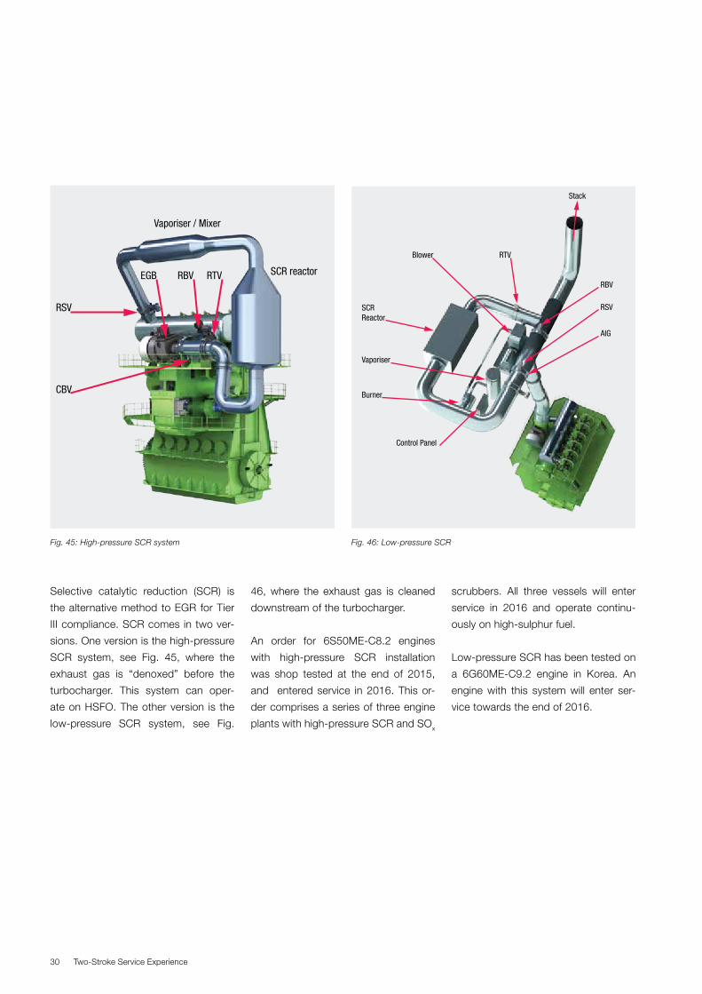
Selective catalytic reduction (SCR) is
the alternative method to EGR for Tier
III compliance. SCR comes in two ver-
sions. One version is the high-pressure
SCR system, see Fig. 45, where the
exhaust gas is “denoxed” before the
turbocharger. This system can oper-
ate on HSFO. The other version is the
low-pressure SCR system, see Fig.
46, where the exhaust gas is cleaned
downstream of the turbocharger.
An order for 6S50ME-C8.2 engines
with high-pressure SCR installation
was shop tested at the end of 2015,
and entered service in 2016. This or-
der comprises a series of three engine
plants with high-pressure SCR and SOx
scrubbers. All three vessels will enter
service in 2016 and operate continu-
ously on high-sulphur fuel.
Low-pressure SCR has been tested on
a 6G60ME-C9.2 engine in Korea. An
engine with this system will enter ser-
vice towards the end of 2016.
Fig. 45: High-pressure SCR system
Vaporiser / Mixer
EGB RBV RTV
RSV
CBV
SCR reactor
SCRReactor
Vaporiser
Burner
Control Panel
Blower RTV
RBV
RSV
AIG
Stack
Fig. 46: Low-pressure SCR

Two-Stroke Service Experience 31
ME-GI Service Experience
The gas channel pressure sensors in-
stalled in the gas blocks, see Fig. 47,
have undergone some development.
The first version of this sensor could
not be ATEX approved and a prelimi-
nary solution with an electric barrier
had to be used on the first engines in
service. The first version of an ATEX
approved gas channel pressure sensor
was too sensitive in relation to engine
vibrations. At the time of writing, new
versions of ATEX approved sensors are
being tested.
A booster pump has been installed in
the low-pressure oil supply line to im-
prove venting of air in the control oil
bores after engine standstill. On the
first two engines in operation, the first
installation had to be modified by sup-
porting the electric motor with brackets
and reducing vibrations from the pipe
connections by means of rubber com-
pensators, see Fig. 48.
Fig 47: ME-GI commissioning experience – gas channel sensors
Fig 48: Modified LPS pump arrangement
Two-Stroke Service Experience32
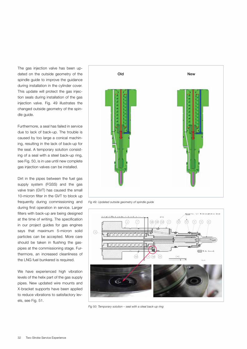
The gas injection valve has been up-
dated on the outside geometry of the
spindle guide to improve the guidance
during installation in the cylinder cover.
This update will protect the gas injec-
tion seals during installation of the gas
injection valve. Fig. 49 illustrates the
changed outside geometry of the spin-
dle guide.
Furthermore, a seal has failed in service
due to lack of back-up. The trouble is
caused by too large a conical machin-
ing, resulting in the lack of back-up for
the seal. A temporary solution consist-
ing of a seal with a steel back-up ring,
see Fig. 50, is in use until new complete
gas injection valves can be installed.
Dirt in the pipes between the fuel gas
supply system (FGSS) and the gas
valve train (GVT) has caused the small
10-micron filter in the GVT to block up
frequently during commissioning and
during first operation in service. Larger
filters with back-up are being designed
at the time of writing. The specification
in our project guides for gas engines
says that maximum 5-micron solid
particles can be accepted. More care
should be taken in flushing the gas-
pipes at the commissioning stage. Fur-
thermore, an increased cleanliness of
the LNG fuel bunkered is required.
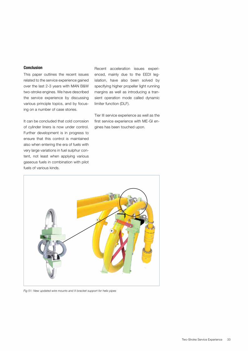
We have experienced high vibration
levels of the helix part of the gas supply
pipes. New updated wire mounts and
X-bracket supports have been applied
to reduce vibrations to satisfactory lev-
els, see Fig. 51.
Fig 49: Updated outside geometry of spindle guide
Fig 50: Temporary solution – seal with a steal back-up ring
Old New
Two-Stroke Service Experience 33
Conclusion
This paper outlines the recent issues
related to the service experience gained
over the last 2-3 years with MAN B&W
two-stroke engines. We have described
the service experience by discussing
various principle topics, and by focus-
ing on a number of case stories.
It can be concluded that cold corrosion
of cylinder liners is now under control.
Further development is in progress to
ensure that this control is maintained
also when entering the era of fuels with
very large variations in fuel sulphur con-
tent, not least when applying various
gaseous fuels in combination with pilot
fuels of various kinds.
Recent acceleration issues experi-
enced, mainly due to the EEDI leg-
islation, have also been solved by
specifying higher propeller light running
margins as well as introducing a tran-
sient operation mode called dynamic
limiter function (DLF).
Tier III service experience as well as the
first service experience with ME-GI en-
gines has been touched upon.
Fig 51: New updated wire mounts and X-bracket support for helix pipes


MAN Diesel & TurboTeglholmsgade 412450 Copenhagen SV, DenmarkPhone +45 33 85 11 00Fax +45 33 85 10 [email protected]
MAN Diesel & Turbo – a member of the MAN Group
All data provided in this document is non-binding. This data serves informational purposes only and is especially not guaranteed in any way. Depending on the subsequent specific individual projects, the relevant data may be subject to changes and will be assessed and determined individually for each project. This will depend on the particular characteristics of each individual project, especially specific site and operational conditions. Copyright © MAN Diesel & Turbo. 5510-0195-00ppr Jul 2016 Printed in Denmark