Embed Size (px)
Citation preview
Tier III Two-Stroke Technology

Contents
Introduction .................................................................................................5
Tier III Technologies ................................................................................5
SCR Application for Tier III ............................................................................6
Fuels for Tier III engines .........................................................................6
Selective catalytic reduction ....................................................................6
SCR system for MAN B&W engines ........................................................7
SCR control system .............................................................................. 10
Results and discussion ......................................................................... 11
SCR and HFO operation ............................................................................. 15
SCR service experience ............................................................................. 15
Future development aspects ................................................................. 15
Conclusion ................................................................................................. 17
EGR Application for Tier III .......................................................................... 18
EGR investigation on 4T50ME-X ........................................................... 18
EGR Tier III confirmation test ................................................................. 19
EGR scrubber performance .................................................................. 19
EGR service test ................................................................................... 21
Preparation of service test on newbuilding with 6S80ME-C9.2 ............... 23
Water treatment system (WTS) .............................................................. 25
EGR high-speed blower ........................................................................ 27
Conclusion ................................................................................................. 29

Tier III Two-Stroke Technology 5
Tier III Two-Stroke Technology
IntroductionThis MAN Diesel & Turbo two-stroke
Tier III paper outlines the status and fu-
ture development efforts in connection
with Tier III technologies, and covers
some of our efforts to develop measur-
ing and calculation tools, securing bet-
ter knowledge of engine processes like
combustion, emission formation and
scavenging of the engine.
Furthermore, details on the SCR devel-
opment, not only for the catalyst appli-
cation, but also on the requirements to
the engine control system in connec-
tion with the SCR application are given.
Also, the status on service tests on the
world’s first Tier III two-stroke engine
will be outlined.
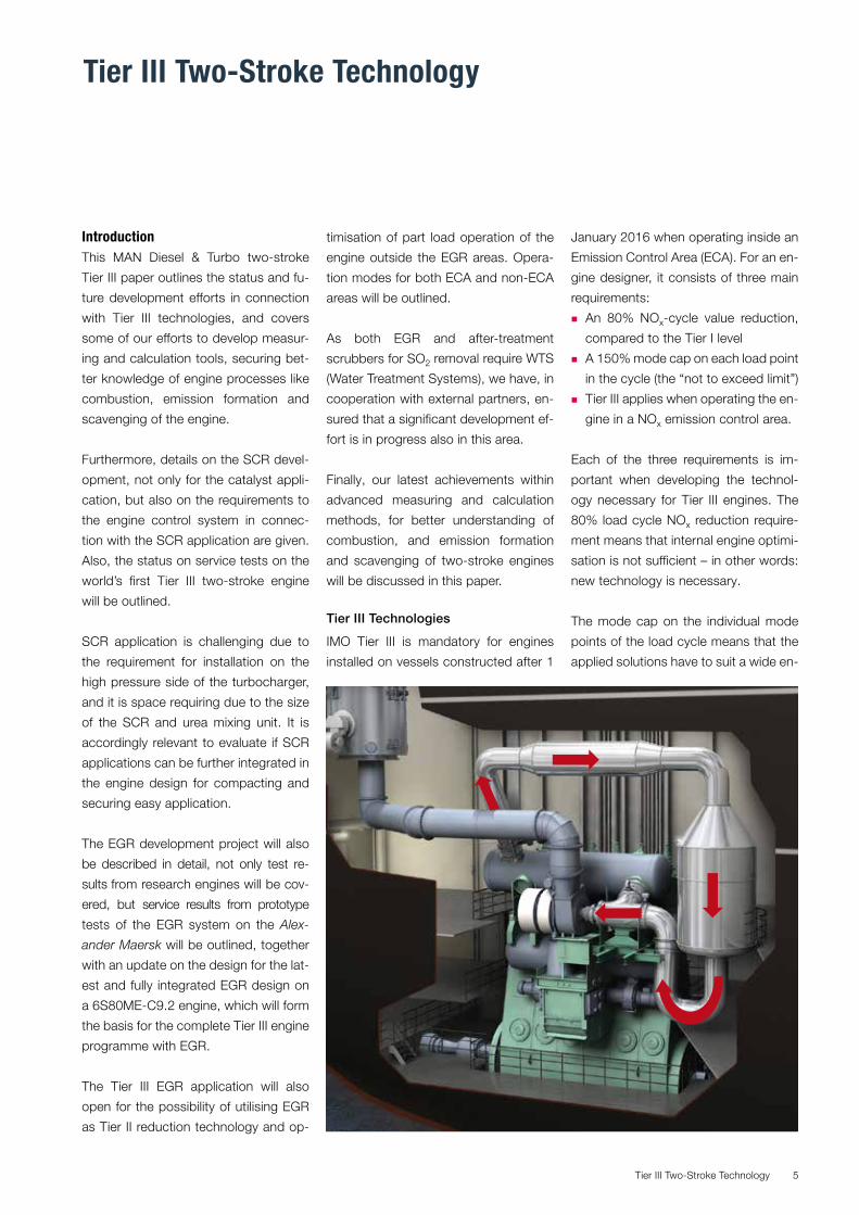
SCR application is challenging due to
the requirement for installation on the
high pressure side of the turbocharger,
and it is space requiring due to the size
of the SCR and urea mixing unit. It is
accordingly relevant to evaluate if SCR
applications can be further integrated in
the engine design for compacting and
securing easy application.
The EGR development project will also
be described in detail, not only test re-
sults from research engines will be cov-
ered, but service results from prototype
tests of the EGR system on the Alex-
ander Maersk will be outlined, together
with an update on the design for the lat-
est and fully integrated EGR design on
a 6S80ME-C9.2 engine, which will form
the basis for the complete Tier III engine
programme with EGR.
The Tier III EGR application will also
open for the possibility of utilising EGR
as Tier II reduction technology and op-
timisation of part load operation of the
engine outside the EGR areas. Opera-
tion modes for both ECA and non-ECA
areas will be outlined.
As both EGR and after-treatment
scrubbers for SO2 removal require WTS
(Water Treatment Systems), we have, in
cooperation with external partners, en-
sured that a significant development ef-
fort is in progress also in this area.
Finally, our latest achievements within
advanced measuring and calculation
methods, for better understanding of
combustion, and emission formation
and scavenging of two-stroke engines
will be discussed in this paper.
Tier III Technologies
IMO Tier III is mandatory for engines
installed on vessels constructed after 1
January 2016 when operating inside an
Emission Control Area (ECA). For an en-
gine designer, it consists of three main
requirements:
� An 80% NOx-cycle value reduction,
compared to the Tier I level
� A 150% mode cap on each load point
in the cycle (the “not to exceed limit”)
� Tier III applies when operating the en-
gine in a NOx emission control area.
Each of the three requirements is im-
portant when developing the technol-
ogy necessary for Tier III engines. The
80% load cycle NOx reduction require-
ment means that internal engine optimi-
sation is not sufficient – in other words:
new technology is necessary.
The mode cap on the individual mode
points of the load cycle means that the
applied solutions have to suit a wide en-
Tier III Two-Stroke Technology6
NO
40% urea solutionCO (NH2)2 • 5(H2O)
Exhaust gasNO2
N2
NH3
H2O
SCRReactor
4NO + 4NH3 + O2 = 4N2 + 6H206NO2 + 8NH3 = 7N2 + 12H20
NO
N
N N
NN
H
O
HH
HH
H
N N N
N
NN
OO
H
H
H
H
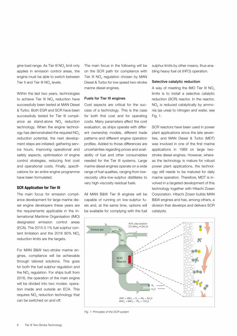
Fig. 1: Principles of the SCR system
gine load range. As Tier III NOx limit only
applies in emission control areas, the
engine must be able to switch between
Tier II and Tier III NOx levels.
Within the last two years, technologies
to achieve Tier III NOx reduction have
successfully been tested at MAN Diesel
& Turbo. Both EGR and SCR have been
successfully tested for Tier III compli-
ance as stand-alone NOx reduction
technology. When the engine technol-
ogy has demonstrated the required NOx
reduction potential, the next develop-
ment steps are initiated: gathering serv-
ice hours, improving operational and
safety aspects, optimisation of engine
control strategies, reducing first cost
and operational costs. Finally, specifi-
cations for an entire engine programme
have been formulated.
SCR Application for Tier III
The main focus for emission compli-
ance development for large marine die-
sel engine developers these years are
the requirements applicable in the In-
ternational Maritime Organisation (IMO)
designated emission control areas
(ECA). The 2015 0.1% fuel sulphur con-
tent limitation and the 2016 80% NOx
reduction limits are the targets.
For MAN B&W two-stroke marine en-
gines, compliance will be achievable
through tailored solutions. This goes
for both the fuel sulphur regulation and
the NOx regulation. For ships built from
2016, the operation of the main engine
will be divided into two modes: opera-
tion inside and outside an ECA. This
requires NOx reduction technology that
can be switched on and off.
The main focus in the following will be
on the SCR path for compliance with
Tier III NOx regulation chosen by MAN
Diesel & Turbo for low speed two-stroke
marine diesel engines.
Fuels for Tier III engines
Cost aspects are critical for the suc-
cess of a technology. This is the case
for both first cost and for operating
costs. Many parameters affect the cost
evaluation, as ships operate with differ-
ent ownership models, different trade
patterns and different engine operation
profiles. Added to those differences are
uncertainties regarding prices and avail-
ability of fuel and other consumables
needed for the Tier III systems. Large
marine diesel engines operate on a wide
range of fuel qualities, ranging from low-
viscosity ultra-low-sulphur distillates to
very high-viscosity residual fuels.
All MAN B&W Tier III engines will be
capable of running on low-sulphur fu-
els and, at the same time, options will
be available for complying with the fuel
sulphur limits by other means, thus ena-
bling heavy fuel oil (HFO) operation.
Selective catalytic reduction
A way of meeting the IMO Tier III NOx
limits is to install a selective catalytic
reduction (SCR) reactor. In the reactor,
NOx is reduced catalytically by ammo-
nia (as urea) to nitrogen and water, see
Fig. 1.
SCR reactors have been used in power
plant applications since the late seven-
ties, and MAN Diesel & Turbo (MDT)
was involved in one of the first marine
applications in 1989 on large two-
stroke diesel engines. However, where-
as the technology is mature for robust
power plant applications, the technol-
ogy still needs to be matured for daily
marine operation. Therefore, MDT is in-
volved in a targeted development of this
technology together with Hitachi Zosen
Corporation. Hitachi Zosen builds MAN
B&W engines and has, among others, a
division that develops and delivers SCR
catalysts.
Tier III Two-Stroke Technology 7
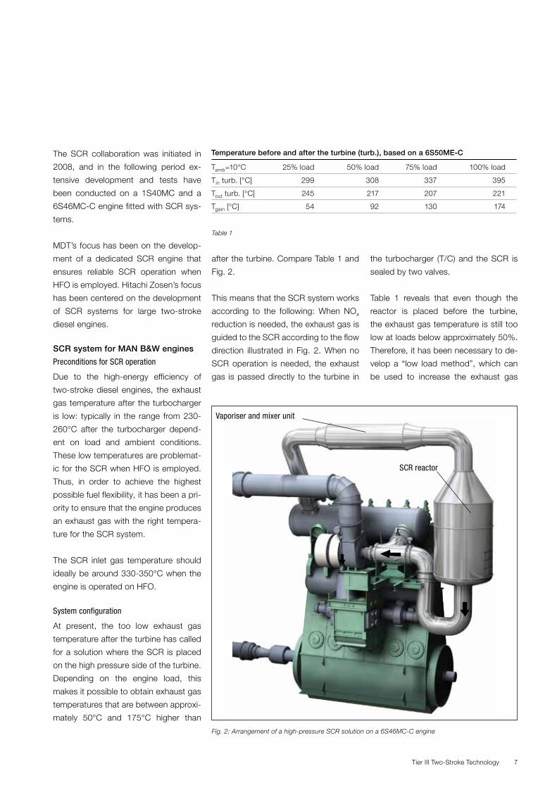
Fig. 2: Arrangement of a high-pressure SCR solution on a 6S46MC-C engine
SCR reactor
The SCR collaboration was initiated in
2008, and in the following period ex-
tensive development and tests have
been conducted on a 1S40MC and a
6S46MC-C engine fitted with SCR sys-
tems.
MDT’s focus has been on the develop-
ment of a dedicated SCR engine that
ensures reliable SCR operation when
HFO is employed. Hitachi Zosen’s focus
has been centered on the development
of SCR systems for large two-stroke
diesel engines.
SCR system for MAN B&W engines
Preconditions for SCR operation
Due to the high-energy efficiency of
two-stroke diesel engines, the exhaust
gas temperature after the turbocharger
is low: typically in the range from 230-
260°C after the turbocharger depend-
ent on load and ambient conditions.
These low temperatures are problemat-
ic for the SCR when HFO is employed.
Thus, in order to achieve the highest
possible fuel flexibility, it has been a pri-
ority to ensure that the engine produces
an exhaust gas with the right tempera-
ture for the SCR system.
The SCR inlet gas temperature should
ideally be around 330-350°C when the
engine is operated on HFO.
System configuration
At present, the too low exhaust gas
temperature after the turbine has called
for a solution where the SCR is placed
on the high pressure side of the turbine.
Depending on the engine load, this
makes it possible to obtain exhaust gas
temperatures that are between approxi-
mately 50°C and 175°C higher than
Temperature before and after the turbine (turb.), based on a 6S50ME-C
Tamb=10°C 25% load 50% load 75% load 100% load
Tin turb. [°C] 299 308 337 395
Tout turb. [°C] 245 217 207 221
Tgain [°C] 54 92 130 174
Table 1
Vaporiser and mixer unit
after the turbine. Compare Table 1 and
Fig. 2.
This means that the SCR system works
according to the following: When NOx
reduction is needed, the exhaust gas is
guided to the SCR according to the flow
direction illustrated in Fig. 2. When no
SCR operation is needed, the exhaust
gas is passed directly to the turbine in
the turbocharger (T/C) and the SCR is
sealed by two valves.
Table 1 reveals that even though the
reactor is placed before the turbine,
the exhaust gas temperature is still too
low at loads below approximately 50%.
Therefore, it has been necessary to de-
velop a “low load method”, which can
be used to increase the exhaust gas
Tier III Two-Stroke Technology8
Items to be controlled by the ECS
Item Function
V1 Maintains acceptable turbocharger performance
V2 Limits effects on engine performance
V3 Seals reactor together with V2
CBV Increases low-load exhaust gas temperature
A/B Stabilises T/C
Table 2
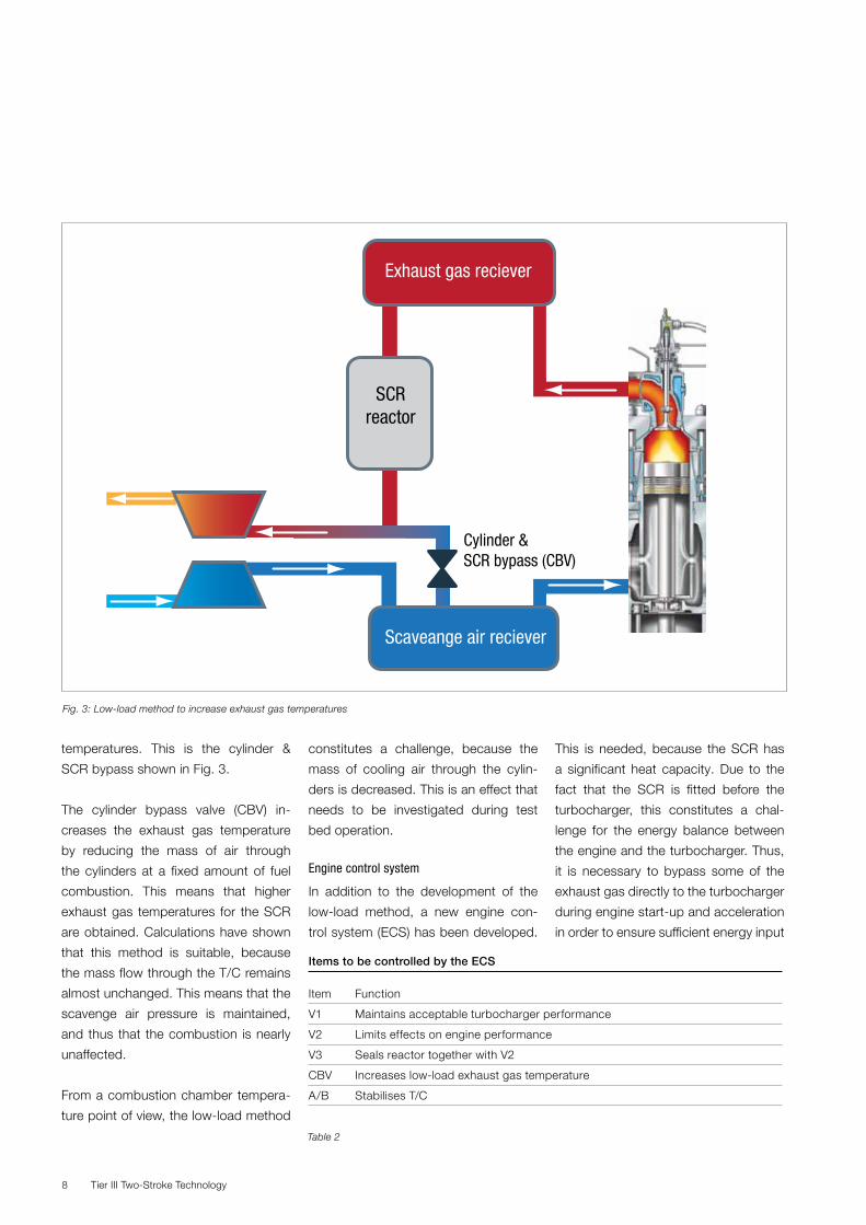
temperatures. This is the cylinder &
SCR bypass shown in Fig. 3.
The cylinder bypass valve (CBV) in-
creases the exhaust gas temperature
by reducing the mass of air through
the cylinders at a fixed amount of fuel
combustion. This means that higher
exhaust gas temperatures for the SCR
are obtained. Calculations have shown
that this method is suitable, because
the mass flow through the T/C remains
almost unchanged. This means that the
scavenge air pressure is maintained,
and thus that the combustion is nearly
unaffected.
From a combustion chamber tempera-
ture point of view, the low-load method
constitutes a challenge, because the
mass of cooling air through the cylin-
ders is decreased. This is an effect that
needs to be investigated during test
bed operation.
Engine control system
In addition to the development of the
low-load method, a new engine con-
trol system (ECS) has been developed.
This is needed, because the SCR has
a significant heat capacity. Due to the
fact that the SCR is fitted before the
turbocharger, this constitutes a chal-
lenge for the energy balance between
the engine and the turbocharger. Thus,
it is necessary to bypass some of the
exhaust gas directly to the turbocharger
during engine start-up and acceleration
in order to ensure sufficient energy input
Fig. 3: Low-load method to increase exhaust gas temperatures
Exhaust gas reciever
Scaveange air reciever
SCRreactor
Cylinder &SCR bypass (CBV)
Tier III Two-Stroke Technology 9
to the turbine. For the same reason, it
may be necessary to bypass the turbine
during de-acceleration of the engine, as
the energy level of the exhaust gas from
the SCR is too high. Lastly, the low-load
method needs to be controlled to en-
sure the right temperature at the SCR
inlet. As a result, a dedicated ECS has
been developed for the SCR engine.
The outline of the ECS is illustrated in
Fig. 4.
The success criteria for the ECS are:
� To ensure acceptable engine per-
formance
� To ensure quick heating of the SCR
system
� To ensure a minimum exhaust gas
temperature Tmin.
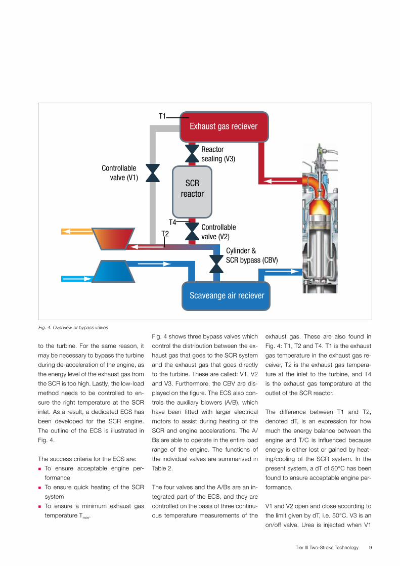
Fig. 4 shows three bypass valves which
control the distribution between the ex-
haust gas that goes to the SCR system
and the exhaust gas that goes directly
to the turbine. These are called: V1, V2
and V3. Furthermore, the CBV are dis-
played on the figure. The ECS also con-
trols the auxiliary blowers (A/B), which
have been fitted with larger electrical
motors to assist during heating of the
SCR and engine accelerations. The A/
Bs are able to operate in the entire load
range of the engine. The functions of
the individual valves are summarised in
Table 2.
The four valves and the A/Bs are an in-
tegrated part of the ECS, and they are
controlled on the basis of three continu-
ous temperature measurements of the
exhaust gas. These are also found in
Fig. 4: T1, T2 and T4. T1 is the exhaust
gas temperature in the exhaust gas re-
ceiver, T2 is the exhaust gas tempera-
ture at the inlet to the turbine, and T4
is the exhaust gas temperature at the
outlet of the SCR reactor.
The difference between T1 and T2,
denoted dT, is an expression for how
much the energy balance between the
engine and T/C is influenced because
energy is either lost or gained by heat-
ing/cooling of the SCR system. In the
present system, a dT of 50°C has been
found to ensure acceptable engine per-
formance.
V1 and V2 open and close according to
the limit given by dT, i.e. 50°C. V3 is an
on/off valve. Urea is injected when V1
Fig. 4: Overview of bypass valves
Exhaust gas reciever
Scaveange air reciever
SCRreactor
Controllablevalve (V2)
Cylinder &SCR bypass (CBV)
Reactor sealing (V3)
T1
Controllable valve (V1)
T2
T4
Tier III Two-Stroke Technology10
is fully closed, and the T1 is above the
critical temperature for urea injection.
Based on these three temperature
measurements, the ECS is able to en-
sure that the engine performance is
maintained during deceleration/accel-
eration and heating/cooling of the SCR
system. Furthermore, the ECS ensures
that the exhaust gas temperature is
kept above a certain Tmin by adjusting
the position of the CBV.
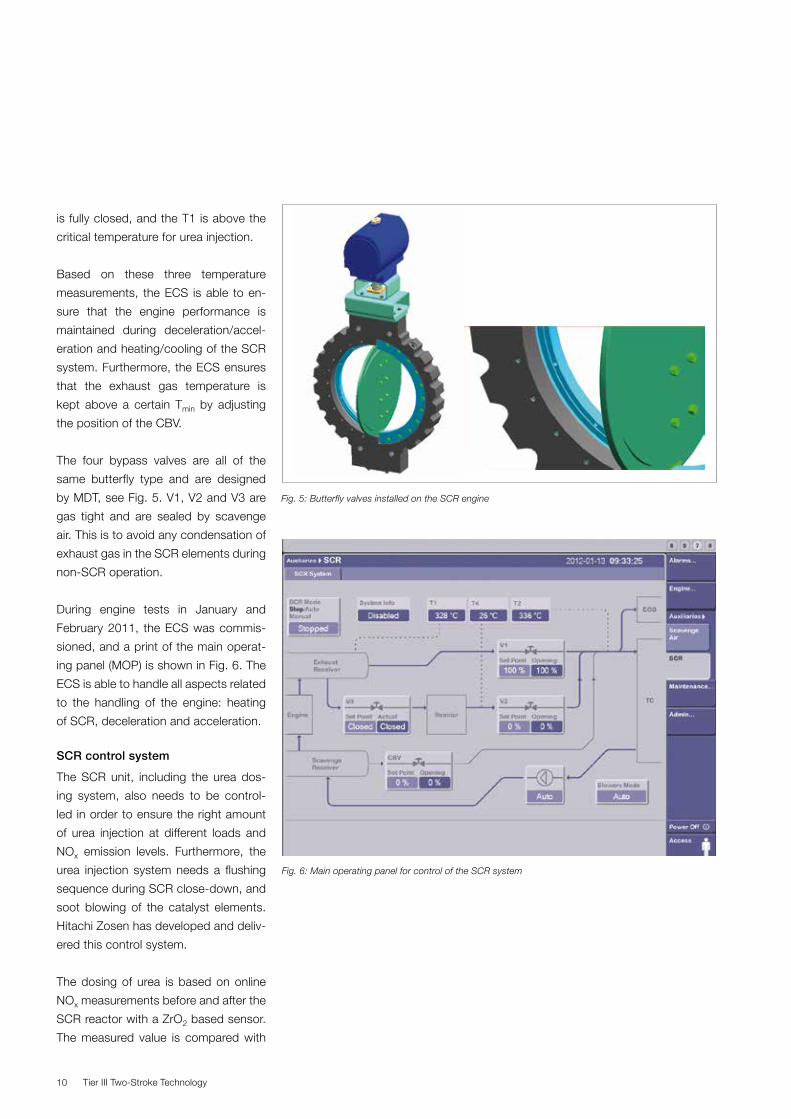
The four bypass valves are all of the
same butterfly type and are designed
by MDT, see Fig. 5. V1, V2 and V3 are
gas tight and are sealed by scavenge
air. This is to avoid any condensation of
exhaust gas in the SCR elements during
non-SCR operation.
During engine tests in January and
February 2011, the ECS was commis-
sioned, and a print of the main operat-
ing panel (MOP) is shown in Fig. 6. The
ECS is able to handle all aspects related
to the handling of the engine: heating
of SCR, deceleration and acceleration.
SCR control system
The SCR unit, including the urea dos-
ing system, also needs to be control-
led in order to ensure the right amount
of urea injection at different loads and
NOx emission levels. Furthermore, the
urea injection system needs a flushing
sequence during SCR close-down, and
soot blowing of the catalyst elements.
Hitachi Zosen has developed and deliv-
ered this control system.
The dosing of urea is based on online
NOx measurements before and after the
SCR reactor with a ZrO2 based sensor.
The measured value is compared with
Fig. 5: Butterfly valves installed on the SCR engine
Fig. 6: Main operating panel for control of the SCR system
Tier III Two-Stroke Technology 11
an estimated NOx value based on test
bed measurement (NOx map as a func-
tion of engine load). This is to ensure
that no under/over dosing of urea takes
place in case of a sensor error.
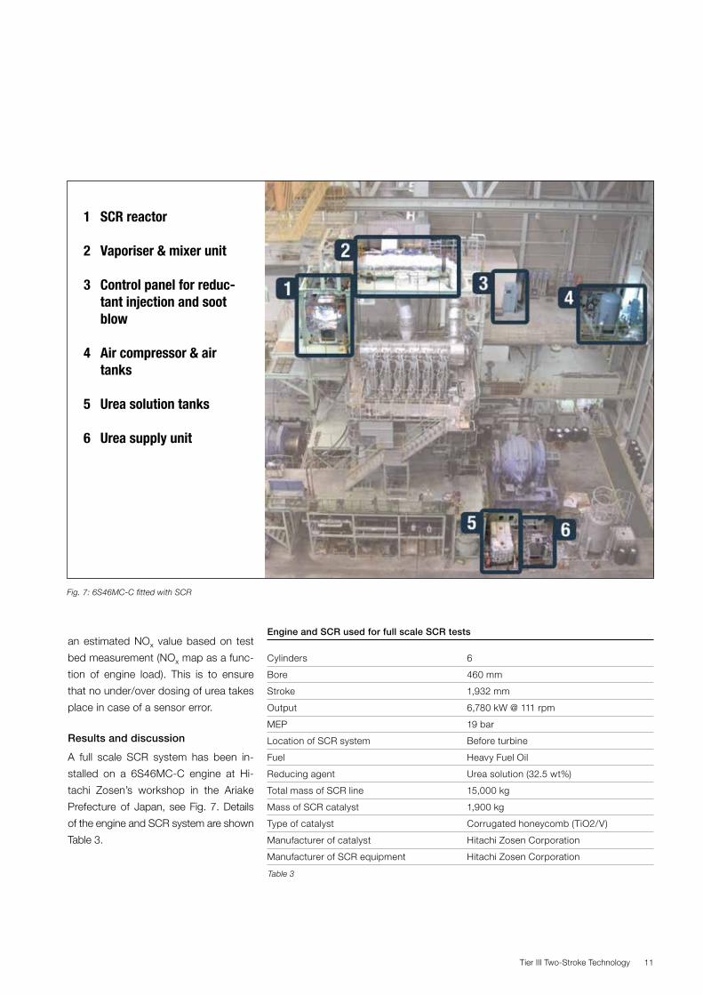
Results and discussion
A full scale SCR system has been in-
stalled on a 6S46MC-C engine at Hi-
tachi Zosen’s workshop in the Ariake
Prefecture of Japan, see Fig. 7. Details
of the engine and SCR system are shown
Table 3.
Engine and SCR used for full scale SCR tests
Cylinders 6
Bore 460 mm
Stroke 1,932 mm
Output 6,780 kW @ 111 rpm
MEP 19 bar
Location of SCR system Before turbine
Fuel Heavy Fuel Oil
Reducing agent Urea solution (32.5 wt%)
Total mass of SCR line 15,000 kg
Mass of SCR catalyst 1,900 kg
Type of catalyst Corrugated honeycomb (TiO2/V)
Manufacturer of catalyst Hitachi Zosen Corporation
Manufacturer of SCR equipment Hitachi Zosen Corporation
Fig. 7: 6S46MC-C fitted with SCR
Table 3
1 SCR reactor
2 Vaporiser & mixer unit
3 Control panel for reduc-tant injection and soot blow
4 Air compressor & air tanks
5 Urea solution tanks
6 Urea supply unit
Tier III Two-Stroke Technology12
A huge number of tests with various
goals were conducted on this system in
the period from January to April 2011.
The objectives were the following:
� To investigate low-load method
� To commission ECS
� To verify Tier III compliance
� To gain experience on SCR operation
in combination with HFO.
Low-load method at 25% engine load
The low-load method has been tested
at engine loads ranging from approxi-
mately 10% to 50%. Three issues were
the main objectives:
� Possible temperature increase of ex-
haust gas entering the SCR
� Penalty on combustion chamber
components temperatures
� Penalty on SFOC.
In the following, the results obtained
at the lowest IMO load point (25% en-
gine load) is discussed – this is where
the lowest T1 temperature is obtained.
The amount of scavenge air through the
bypass was adjusted and the SFOC
and combustion chamber temperature
(CCT) was measured, among other
things. The CCT measurements showed
that the average temperature of the ex-
haust gas spindle (X/V spindle) was the
most influenced component, for which
reason the other combustion chamber
components (cylinder liner and piston)
are omitted in the discussion.
During the reference test, the exhaust
gas temperature, T1, was measured to
258°C. This means that T1 should be
increased by at least 72°C to obtain
a temperature above the mentioned
330°C minimum SCR inlet temperature.
Tem
pera
ture
in d
g. C
Time in sec.
SCR/cylinder bypass in action
CBV Feedback
V2 Feedback
V1 Feedback
0
0 200 400 600 800 1000 1200
20
40
60
80
100
120
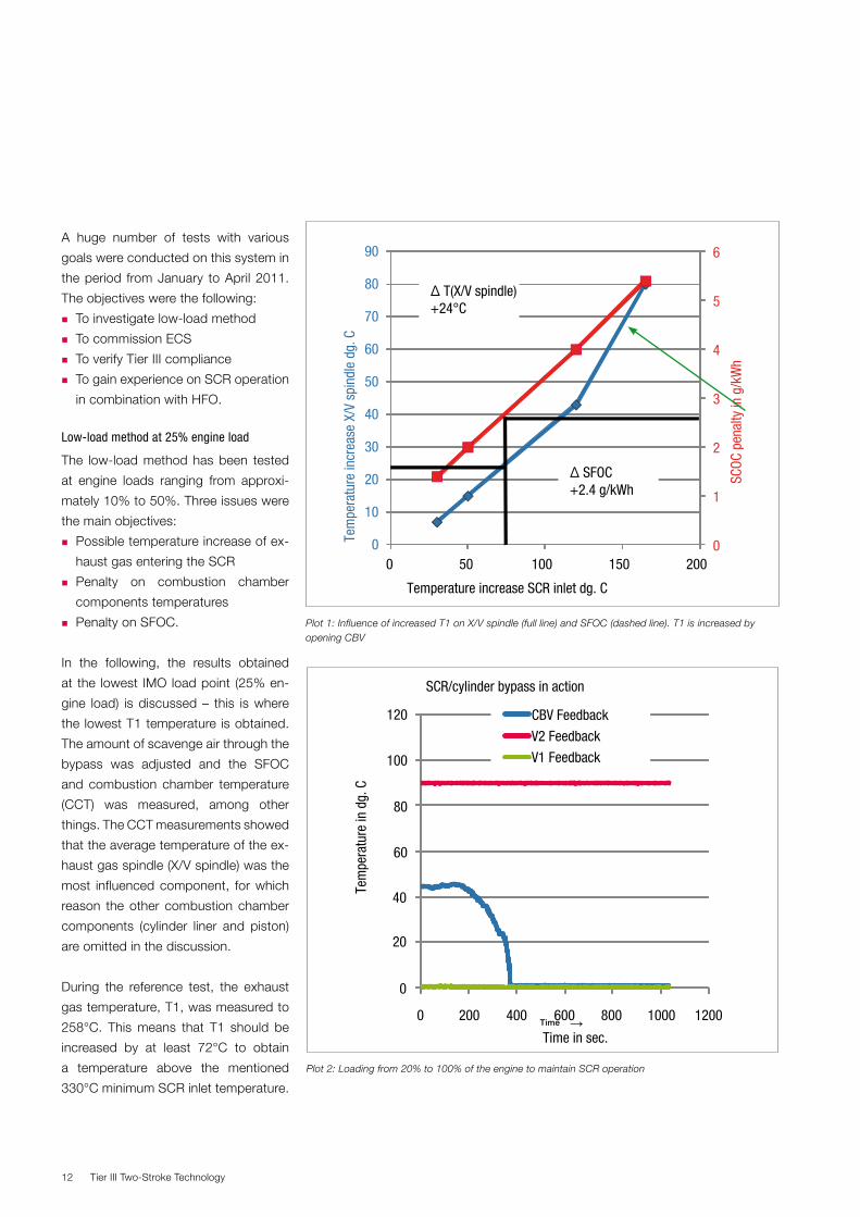
Plot 2: Loading from 20% to 100% of the engine to maintain SCR operation
Time →
Plot 1: Influence of increased T1 on X/V spindle (full line) and SFOC (dashed line). T1 is increased by opening CBV
0
1
2
3
4
5
6
0
10
20
30
40
50
60
70
80
90
0 50 100 150 200
SCOC
pen
alty
in g
/kW
h
Tem
pera
ture
incr
ease
X/V
spi
ndle
dg.
C
Temperature increase SCR inlet dg. C
Δ T(X/V spindle)+24°C
Δ SFOC+2.4 g/kWh
Tier III Two-Stroke Technology 13
With fully open CBV, T1 can be in-
creased by 165°C. This means that the
desired temperature increase of 72°C is
obtainable. From Plot 1, it is revealed
that this temperature increase causes
an increased heat load of approx. 25°C
on exhaust valve and an SFOC penalty
of approx. 2-3 g/kWh.
Based on the investigations of the low-
load method, it has been concluded that for
the present system, the CBV will be em-
ployed. However, in future applications,
increased scavenge air temperature in
combination with CBV may be needed
to ensure SCR operation at even lower
engine loads.
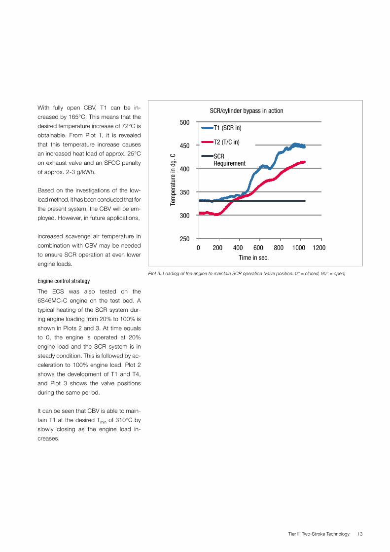
Engine control strategy
The ECS was also tested on the
6S46MC-C engine on the test bed. A
typical heating of the SCR system dur-
ing engine loading from 20% to 100% is
shown in Plots 2 and 3. At time equals
to 0, the engine is operated at 20%
engine load and the SCR system is in
steady condition. This is followed by ac-
celeration to 100% engine load. Plot 2
shows the development of T1 and T4,
and Plot 3 shows the valve positions
during the same period.
It can be seen that CBV is able to main-
tain T1 at the desired Tmin of 310°C by
slowly closing as the engine load in-
creases.
250
300
350
400
450
500
0 200 400 600 800 1000 1200
Tem
pera
ture
in d
g. C
Time in sec.
SCR/cylinder bypass in action
T1 (SCR in)
T2 (T/C in)
SCR Requirement
Plot 3: Loading of the engine to maintain SCR operation (valve position: 0° = closed, 90° = open)
Tier III Two-Stroke Technology14
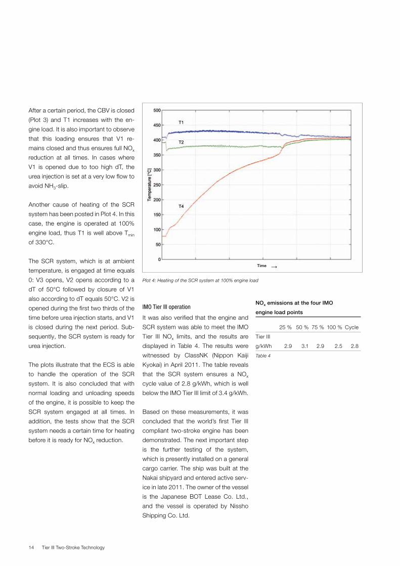
Plot 4: Heating of the SCR system at 100% engine load
Time →
NOx emissions at the four IMO
engine load points
25 % 50 % 75 % 100 % Cycle
Tier III
g/kWh 2.9 3.1 2.9 2.5 2.8
Table 4
After a certain period, the CBV is closed
(Plot 3) and T1 increases with the en-
gine load. It is also important to observe
that this loading ensures that V1 re-
mains closed and thus ensures full NOx
reduction at all times. In cases where
V1 is opened due to too high dT, the
urea injection is set at a very low flow to
avoid NH3-slip.
Another cause of heating of the SCR
system has been posted in Plot 4. In this
case, the engine is operated at 100%
engine load, thus T1 is well above Tmin
of 330°C.
The SCR system, which is at ambient
temperature, is engaged at time equals
0: V3 opens, V2 opens according to a
dT of 50°C followed by closure of V1
also according to dT equals 50°C. V2 is
opened during the first two thirds of the
time before urea injection starts, and V1
is closed during the next period. Sub-
sequently, the SCR system is ready for
urea injection.
The plots illustrate that the ECS is able
to handle the operation of the SCR
system. It is also concluded that with
normal loading and unloading speeds
of the engine, it is possible to keep the
SCR system engaged at all times. In
addition, the tests show that the SCR
system needs a certain time for heating
before it is ready for NOx reduction.
IMO Tier III operation
It was also verified that the engine and
SCR system was able to meet the IMO
Tier III NOx limits, and the results are
displayed in Table 4. The results were
witnessed by ClassNK (Nippon Kaiji
Kyokai) in April 2011. The table reveals
that the SCR system ensures a NOx
cycle value of 2.8 g/kWh, which is well
below the IMO Tier III limit of 3.4 g/kWh.
Based on these measurements, it was
concluded that the world’s first Tier III
compliant two-stroke engine has been
demonstrated. The next important step
is the further testing of the system,
which is presently installed on a general
cargo carrier. The ship was built at the
Nakai shipyard and entered active serv-
ice in late 2011. The owner of the vessel
is the Japanese BOT Lease Co. Ltd.,
and the vessel is operated by Nissho
Shipping Co. Ltd.
Tier III Two-Stroke Technology 15
SCR and HFO operation
It is well known that the combination
of sulphur containing fuels and SCR
is challenging. This is because of the
transformation of SO2 to SO3 inside
the SCR. This allows formation of ABS
and white plumes. In addition, it is also
known that the inherent content of va-
nadium in HFO makes the SO2 oxida-
tion more pronounced over time. It
is necessary to demonstrate that the
present SCR system has been de-
signed in a way that suppresses these
undesired side reactions. This is a part
of the service test which was initiated in
the last part of 2011.
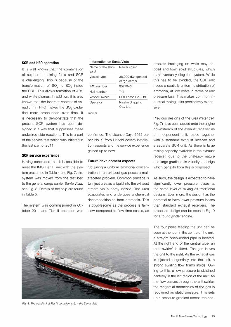
SCR service experience
Having concluded that it is possible to
meet the IMO Tier III limit with the sys-
tem presented in Table 4 and Fig. 7, this
system was moved from the test bed
to the general cargo carrier Santa Vista,
see Fig. 8. Details of the ship are found
in Table 5.
The system was commissioned in Oc-
tober 2011 and Tier III operation was
Fig. 8: The world’s first Tier III compliant ship – the Santa Vista
Information on Santa Vista
Name of the ship-yard
Naikai Zosen
Vessel type 38,000 dwt general cargo carrier
IMO number 9527946
Hull number 744
Vessel Owner BOT Lease Co., Ltd.
Operator Nissho Shipping Co., Ltd.
confirmed. The Licence Days 2012 pa-
per No. 9 from Hitachi covers installa-
tion aspects and the service experience
gained up to now.
Future development aspects
Obtaining a uniform ammonia concen-
tration in an exhaust gas poses a mul-
tifaceted problem. Common practice is
to inject urea as a liquid into the exhaust
stream via a spray nozzle. The urea
evaporates and undergoes a chemical
decomposition to form ammonia. This
is troublesome as the process is fairly
slow compared to flow time scales, as
Table 5
droplets impinging on walls may de-
posit and form solid structures, which
may eventually clog the system. While
this has to be avoided, the SCR unit
needs a spatially uniform distribution of
ammonia, at low costs in terms of unit
pressure loss. This makes common in-
dustrial mixing units prohibitively expen-
sive.
Previous designs of the urea mixer (ref.
Fig. 7) have been added onto the engine
downstream of the exhaust receiver as
an independent unit, piped together
with a standard exhaust receiver and
a separate SCR unit. As there is large
mixing capacity available in the exhaust
receiver, due to the unsteady nature
and large gradients in velocity, a design
which benefits from this is proposed.
As such, the design is expected to have
significantly lower pressure losses at
the same level of mixing as traditional
designs. Even more, the design has the
potential to have lower pressure losses
than standard exhaust receivers. The
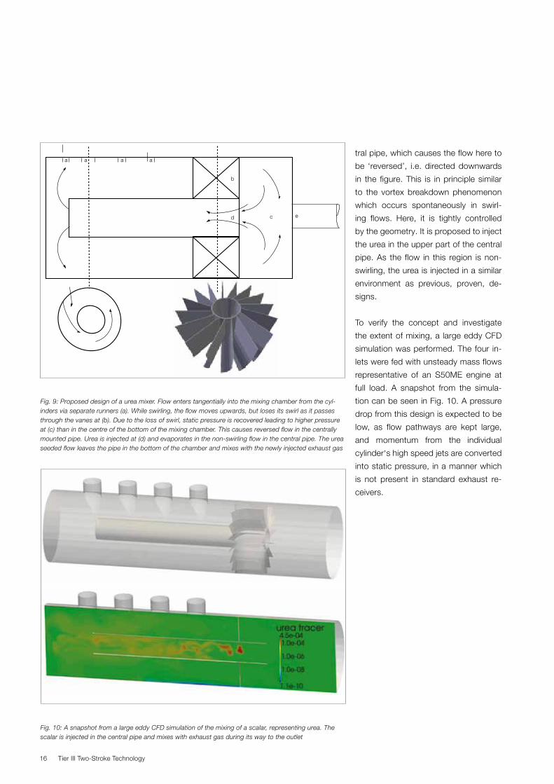
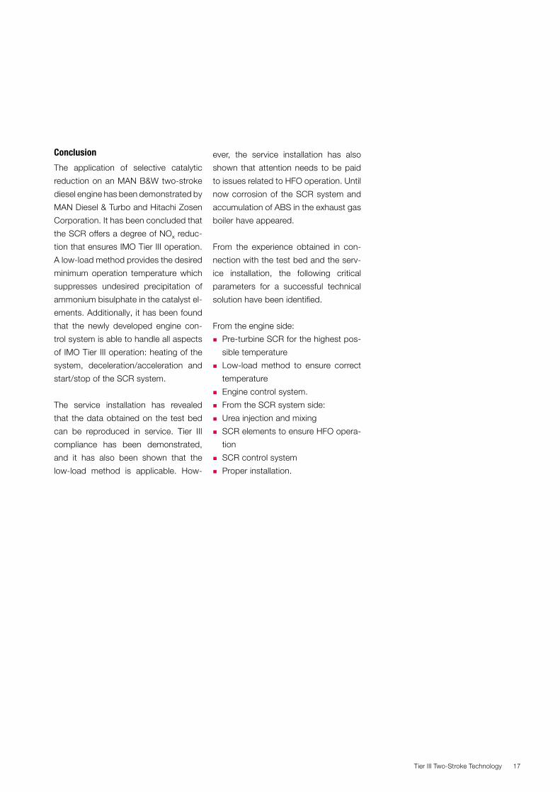
proposed design can be seen in Fig. 9
for a four-cylinder engine.
The four pipes feeding the unit can be
seen at the top. In the centre of the unit,
a straight open-ended pipe is located.
At the right end of the central pipe, an
‘anti swirler’ is fitted. The gas leaves
the unit to the right. As the exhaust gas
is injected tangentially into the unit, a
strong swirling flow forms inside. Ow-
ing to this, a low pressure is obtained
centrally in the left region of the unit. As
the flow passes through the anti swirler,
the tangential momentum of the gas is
recovered as static pressure. This sets
up a pressure gradient across the cen-
Tier III Two-Stroke Technology16
a a a a
b
d c e
Fig. 10: A snapshot from a large eddy CFD simulation of the mixing of a scalar, representing urea. The scalar is injected in the central pipe and mixes with exhaust gas during its way to the outlet
Fig. 9: Proposed design of a urea mixer. Flow enters tangentially into the mixing chamber from the cyl-inders via separate runners (a). While swirling, the flow moves upwards, but loses its swirl as it passes through the vanes at (b). Due to the loss of swirl, static pressure is recovered leading to higher pressure at (c) than in the centre of the bottom of the mixing chamber. This causes reversed flow in the centrally mounted pipe. Urea is injected at (d) and evaporates in the non-swirling flow in the central pipe. The urea seeded flow leaves the pipe in the bottom of the chamber and mixes with the newly injected exhaust gas
tral pipe, which causes the flow here to
be ‘reversed’, i.e. directed downwards
in the figure. This is in principle similar
to the vortex breakdown phenomenon
which occurs spontaneously in swirl-
ing flows. Here, it is tightly controlled
by the geometry. It is proposed to inject
the urea in the upper part of the central
pipe. As the flow in this region is non-
swirling, the urea is injected in a similar
environment as previous, proven, de-
signs.
To verify the concept and investigate
the extent of mixing, a large eddy CFD
simulation was performed. The four in-
lets were fed with unsteady mass flows
representative of an S50ME engine at
full load. A snapshot from the simula-
tion can be seen in Fig. 10. A pressure
drop from this design is expected to be
low, as flow pathways are kept large,
and momentum from the individual
cylinder,s high speed jets are converted
into static pressure, in a manner which
is not present in standard exhaust re-
ceivers.
Tier III Two-Stroke Technology 17
Conclusion
The application of selective catalytic
reduction on an MAN B&W two-stroke
diesel engine has been demonstrated by
MAN Diesel & Turbo and Hitachi Zosen
Corporation. It has been concluded that
the SCR offers a degree of NOx reduc-
tion that ensures IMO Tier III operation.
A low-load method provides the desired
minimum operation temperature which
suppresses undesired precipitation of
ammonium bisulphate in the catalyst el-
ements. Additionally, it has been found
that the newly developed engine con-
trol system is able to handle all aspects
of IMO Tier III operation: heating of the
system, deceleration/acceleration and
start/stop of the SCR system.
The service installation has revealed
that the data obtained on the test bed
can be reproduced in service. Tier III
compliance has been demonstrated,
and it has also been shown that the
low-load method is applicable. How-
ever, the service installation has also
shown that attention needs to be paid
to issues related to HFO operation. Until
now corrosion of the SCR system and
accumulation of ABS in the exhaust gas
boiler have appeared.
From the experience obtained in con-
nection with the test bed and the serv-
ice installation, the following critical
parameters for a successful technical
solution have been identified.
From the engine side:
� Pre-turbine SCR for the highest pos-
sible temperature
� Low-load method to ensure correct
temperature
� Engine control system.
� From the SCR system side:
� Urea injection and mixing
� SCR elements to ensure HFO opera-
tion
� SCR control system
� Proper installation.
Tier III Two-Stroke Technology18
EGR Application for Tier III
Since the ratification of the IMO Tier III
criteria for NOx emissions from large ma-
rine diesel engines in emission control
areas (ECAs), marine engine manufac-
turers worlwide have been challenged
to develop new measures to reduce
NOx. The extent of the necessary meas-
ures to reduce NOx by up to 80%, in
order to meet the IMO NOx criteria from
1 January 2016, is beyond well-known
adjustments of the combustion proc-
ess in two-stroke diesel engines. NOx
reductions of this magnitude on two-
stroke diesel engines require “add-on”
technologies such as exhaust gas re-
circulation (EGR) or selective catalytic
reduction (SCR) as described above.
In 2004, MAN Diesel & Turbo (MDT)
started the first test program with EGR
on the large 4T50ME-X two-stroke die-
sel test engine in Copenhagen, in order
to verify the effect of EGR. Since the
1970s, the effect of EGR on smaller
four-stroke diesel engines used in the
automotive sector has been known as
a very efficient means to reduce NOx in
combustion engines. The HFO burned
in large marine engines is a challenge
when using EGR, due to the presence
of a high sulphur content and a high
content of solids. Thus, a wet scrubber
was introduced in the EGR system.
In parallel with the EGR investigation on
the 4T50ME-X test engine, MAN Die-
sel & Turbo planned to make a service
test on a ship in order to investigate
the long-term effects on the engine
components. In March 2010, a retrofit
EGR system was installed on a 10MW
7S50MC Mk 6 engine on board the
A. P. Moeller Maersk 1,100 teu contain-
er vessel Alexander Maersk.
The following describes the investi-
gation and testing that MAN Diesel &
Turbo has completed with EGR on large
two-stroke diesel engines.
EGR investigation on 4T50ME-X
Engine parameter study
Several comprehensive EGR test pro-
grams have been carried out on the
4T50ME-X test engine to investigate
the mechanism of different variations of
engine parameters when running with
EGR.
The study of engine parameter varia-
tions during EGR operation revealed the
following effects on SFOC and emis-
sions, as also shown in Table 6:
Effects on SFOC
� Increased Pcomp/Pscav
ratio has a posi-
tive impact on the SFOC penalty
� Increased Phyd has a positive impact
on the SFOC penalty
� Increased Pscav has a positive impact
on the SFOC penalty
� Increased Tscav has a negative impact
on the SFOC penalty.
Effects on NOX
� Increased Pscav has a slightly positive
effect on NOX
� Increased Phyd has a moderately neg-
ative effect on NOX
� Increased Pcomp/Pscav has a slightly
negative effect on NOX
� Increased Tscav has a slightly negative
effect on NOX.
Effects on CO:
� Increased Phyd has a significantly
positive effect on CO
� Increased Pscav has a moderately pos-
itive effect on CO
� Increased Pcomp/Pscav has a moderately
positive effect on CO
� Increased Tscav has a moderately neg-
ative effect on CO.
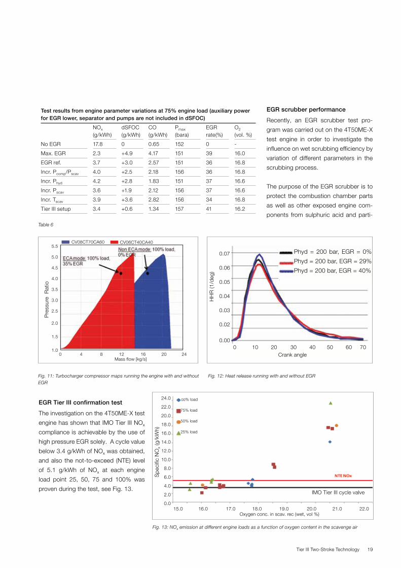
The reduced energy to the turbine side
of the turbocharger, up to around 40%,
when operating the EGR system, results
in reduced scavenge air pressure and
hereby negative effects on the SFOC.
This highlights the need for compen-
sating means as utilisation of cylinder
bypass to compensate the decrease
in the scavenge air pressure. Fig. 11
shows the two very different operating
areas for the compressor running with
and without EGR, corresponding to utili-
sation of a turbocharger cut-out solution.
As can be seen from Fig. 12, the heat
release is only slightly affected by EGR.
Increased hydraulic injection pressure
can compensate for reduced heat re-
lease in the early part of the combus-
tion.
Tier III Two-Stroke Technology 19
Fig. 12: Heat release running with and without EGR
CV08CT70CA60 CV06CT40CA405.5
5.0
4.5 4.0 3.5 3.0 2.5
2.0
1.5
1.0
Pre
ssur
e R
atio
0 4 8 12 16 20 24Mass flow [kg/s]
Phyd = 200 bar, EGR = 0%
Phyd = 200 bar, EGR = 29%
Phyd = 200 bar, EGR = 40%
0 10 20 30 40 50 60 70Crank angle
0.07
0.06
0.05 0.04 0.03
0.02
0.00
HH
R (1
/deg
)
Test results from engine parameter variations at 75% engine load (auxiliary power for EGR lower, separator and pumps are not included in dSFOC)
NOx (g/kWh)
dSFOC (g/kWh)
CO (g/kWh)
Pmax (bara)
EGR rate(%)
O2 (vol. %)
No EGR 17.8 0 0.65 152 0 -
Max. EGR 2.3 +4.9 4.17 151 39 16.0
EGR ref. 3.7 +3.0 2.57 151 36 16.8
Incr. Pcomp/Pscav 4.0 +2.5 2.18 156 36 16.8
Incr. Phyd 4.2 +2.8 1.83 151 37 16.6
Incr. Pscav 3.6 +1.9 2.12 156 37 16.6
Incr. Tscav 3.9 +3.6 2.82 156 34 16.8
Tier III setup 3.4 +0.6 1.34 157 41 16.2
Table 6
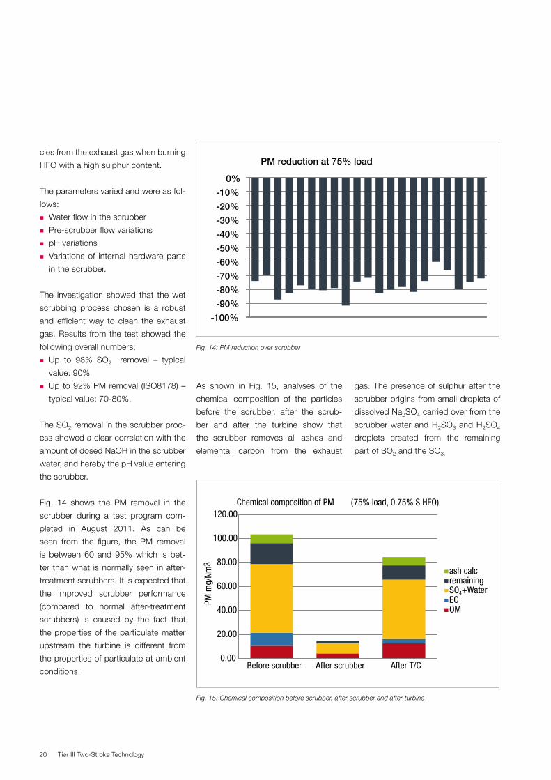
EGR Tier III confirmation test
The investigation on the 4T50ME-X test
engine has shown that IMO Tier III NOx
compliance is achievable by the use of
high pressure EGR solely. A cycle value
below 3.4 g/kWh of NOx was obtained,
and also the not-to-exceed (NTE) level
of 5.1 g/kWh of NOx at each engine
load point 25, 50, 75 and 100% was
proven during the test, see Fig. 13.
Fig. 13: NOx emission at different engine loads as a function of oxygen content in the scavenge air
15.0 16.0 17.0 18.0 19.0 20.0 21.0 22.0 Oxygen conc. in scav. rec (wet, vol %)
IMO Tier III cycle valve
24.0
22.0
20.0
18.0
16.0
14.0
12.0
10.0
8.0
6.0
4.0
2.0
0.0
Spe
cific
NO
x (g
/kW
h)
100% load
75% load
50% load
25% load
EGR scrubber performance
Recently, an EGR scrubber test pro-
gram was carried out on the 4T50ME-X
test engine in order to investigate the
influence on wet scrubbing efficiency by
variation of different parameters in the
scrubbing process.
The purpose of the EGR scrubber is to
protect the combustion chamber parts
as well as other exposed engine com-
ponents from sulphuric acid and parti-
Fig. 11: Turbocharger compressor maps running the engine with and without EGR
Tier III Two-Stroke Technology20
cles from the exhaust gas when burning
HFO with a high sulphur content.
The parameters varied and were as fol-
lows:
� Water flow in the scrubber
� Pre-scrubber flow variations
� pH variations
� Variations of internal hardware parts
in the scrubber.
The investigation showed that the wet
scrubbing process chosen is a robust
and efficient way to clean the exhaust
gas. Results from the test showed the
following overall numbers:
� Up to 98% SO2 removal – typical
value: 90%
� Up to 92% PM removal (ISO8178) –
typical value: 70-80%.
The SO2 removal in the scrubber proc-
ess showed a clear correlation with the
amount of dosed NaOH in the scrubber
water, and hereby the pH value entering
the scrubber.
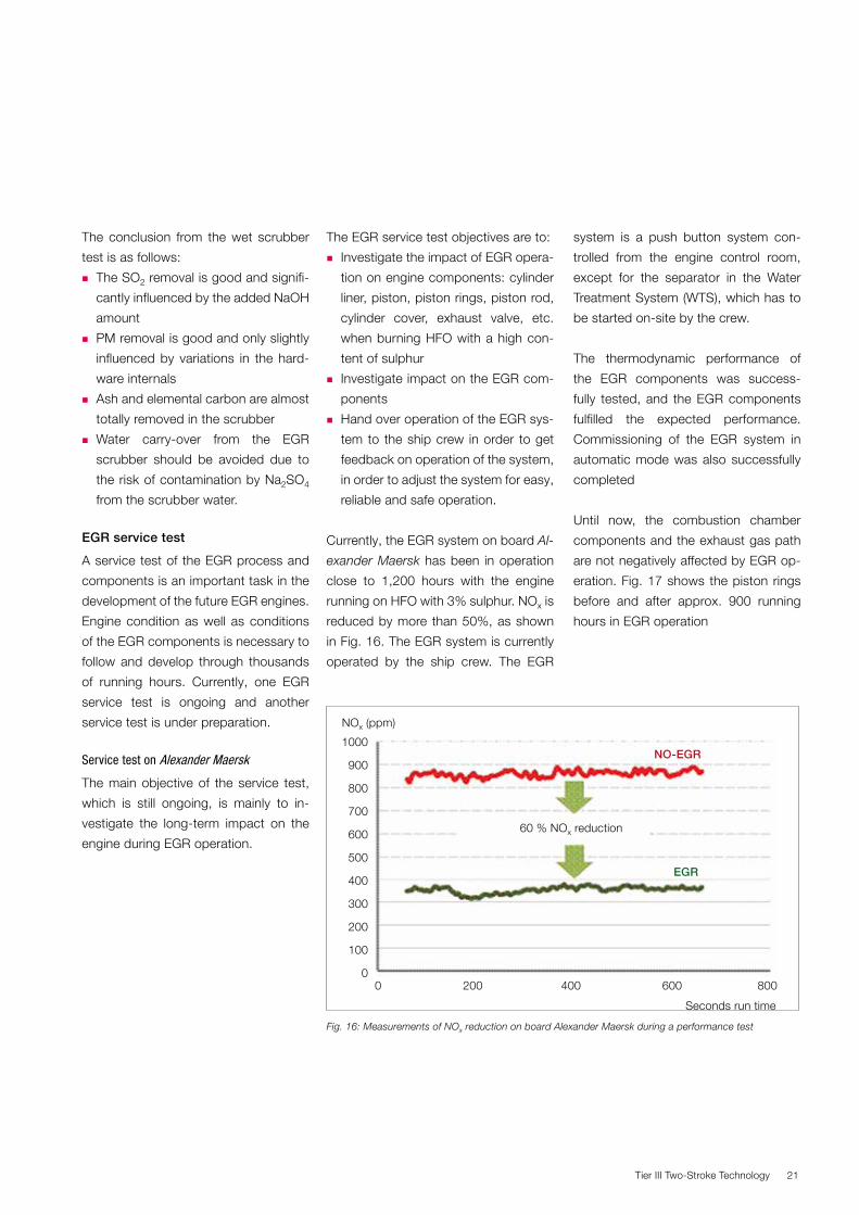
Fig. 14 shows the PM removal in the
scrubber during a test program com-
pleted in August 2011. As can be
seen from the figure, the PM removal
is between 60 and 95% which is bet-
ter than what is normally seen in after-
treatment scrubbers. It is expected that
the improved scrubber performance
(compared to normal after-treatment
scrubbers) is caused by the fact that
the properties of the particulate matter
upstream the turbine is different from
the properties of particulate at ambient
conditions.
-100%
-90%
-80%
-70%
-60%
-50%
-40%
-30%
-20%
-10%
0%
PM reduction at 75% load
0.00
20.00
40.00
60.00
80.00
100.00
120.00
Before scrubber After scrubber After T/C
PM m
g/Nm
3
Chemical composition of PM (75% load, 0.75% S HFO)
ash calcremaining SO4+WaterECOM
Fig. 14: PM reduction over scrubber
Fig. 15: Chemical composition before scrubber, after scrubber and after turbine
As shown in Fig. 15, analyses of the
chemical composition of the particles
before the scrubber, after the scrub-
ber and after the turbine show that
the scrubber removes all ashes and
elemental carbon from the exhaust
gas. The presence of sulphur after the
scrubber origins from small droplets of
dissolved Na2SO4 carried over from the
scrubber water and H2SO3 and H2SO4
droplets created from the remaining
part of SO2 and the SO3.
Tier III Two-Stroke Technology 21
The conclusion from the wet scrubber
test is as follows:
� The SO2 removal is good and signifi-
cantly influenced by the added NaOH
amount
� PM removal is good and only slightly
influenced by variations in the hard-
ware internals
� Ash and elemental carbon are almost
totally removed in the scrubber
� Water carry-over from the EGR
scrubber should be avoided due to
the risk of contamination by Na2SO4
from the scrubber water.
EGR service test
A service test of the EGR process and
components is an important task in the
development of the future EGR engines.
Engine condition as well as conditions
of the EGR components is necessary to
follow and develop through thousands
of running hours. Currently, one EGR
service test is ongoing and another
service test is under preparation.
Service test on Alexander Maersk
The main objective of the service test,
which is still ongoing, is mainly to in-
vestigate the long-term impact on the
engine during EGR operation.
The EGR service test objectives are to:
� Investigate the impact of EGR opera-
tion on engine components: cylinder
liner, piston, piston rings, piston rod,
cylinder cover, exhaust valve, etc.
when burning HFO with a high con-
tent of sulphur
� Investigate impact on the EGR com-
ponents
� Hand over operation of the EGR sys-
tem to the ship crew in order to get
feedback on operation of the system,
in order to adjust the system for easy,
reliable and safe operation.
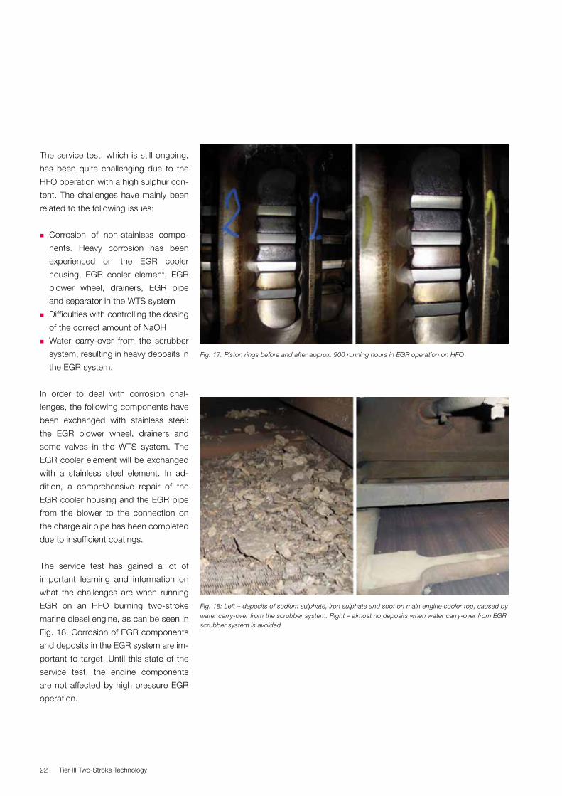
Currently, the EGR system on board Al-
exander Maersk has been in operation
close to 1,200 hours with the engine
running on HFO with 3% sulphur. NOx is
reduced by more than 50%, as shown
in Fig. 16. The EGR system is currently
operated by the ship crew. The EGR
system is a push button system con-
trolled from the engine control room,
except for the separator in the Water
Treatment System (WTS), which has to
be started on-site by the crew.
The thermodynamic performance of
the EGR components was success-
fully tested, and the EGR components
fulfilled the expected performance.
Commissioning of the EGR system in
automatic mode was also successfully
completed
Until now, the combustion chamber
components and the exhaust gas path
are not negatively affected by EGR op-
eration. Fig. 17 shows the piston rings
before and after approx. 900 running
hours in EGR operation
1000
900
800
700
600
500
400
300
200
100
00 200 400 600 800
60 % NOx reduction
NO-EGR
EGR
NOx (ppm)
Seconds run time
Fig. 16: Measurements of NOx reduction on board Alexander Maersk during a performance test
Tier III Two-Stroke Technology22
The service test, which is still ongoing,
has been quite challenging due to the
HFO operation with a high sulphur con-
tent. The challenges have mainly been
related to the following issues:
� Corrosion of non-stainless compo-
nents. Heavy corrosion has been
experienced on the EGR cooler
housing, EGR cooler element, EGR
blower wheel, drainers, EGR pipe
and separator in the WTS system
� Difficulties with controlling the dosing
of the correct amount of NaOH
� Water carry-over from the scrubber
system, resulting in heavy deposits in
the EGR system.
In order to deal with corrosion chal-
lenges, the following components have
been exchanged with stainless steel:
the EGR blower wheel, drainers and
some valves in the WTS system. The
EGR cooler element will be exchanged
with a stainless steel element. In ad-
dition, a comprehensive repair of the
EGR cooler housing and the EGR pipe
from the blower to the connection on
the charge air pipe has been completed
due to insufficient coatings.
The service test has gained a lot of
important learning and information on
what the challenges are when running
EGR on an HFO burning two-stroke
marine diesel engine, as can be seen in
Fig. 18. Corrosion of EGR components
and deposits in the EGR system are im-
portant to target. Until this state of the
service test, the engine components
are not affected by high pressure EGR
operation.
Fig. 18: Left – deposits of sodium sulphate, iron sulphate and soot on main engine cooler top, caused by water carry-over from the scrubber system. Right – almost no deposits when water carry-over from EGR scrubber system is avoided
Fig. 17: Piston rings before and after approx. 900 running hours in EGR operation on HFO
Tier III Two-Stroke Technology 23
Preparation of service test on new-
building with 6S80ME-C9.2
The newest target in the development
of MAN Diesel & Turbo’s two-stroke
EGR engines is a full Tier III compliant
prototype with the EGR components
integrated into the engine structure.
With this project, MAN Diesel & Turbo
targets larger two-stroke EGR engines
with more than one turbocharger utilis-
ing TC cut-out for high engine efficiency
in future ECA areas.
The objectives of the service test are:
� Maturing of the EGR engine concept
for IMO Tier III compliance
� Monitoring combustion chamber
parts and other exposed engine
parts under realistic conditions
� Monitoring of the EGR components'
operational conditions under realistic
operating conditions, i.e. during burn-
ing of HFO
� Education of crew to make reliable
operation of the EGR system and
gain experience for future instruction
books, education and support
� Identifying simplification and cost
down potentials.
WMC EGR blower
Small T/C
T/C cut out
T/C cut out
Scrubber
Mix Cooler
Shut-down valve
Exhaust receiver
Scavenge air receiver
Large T/C
Cooler
WMC
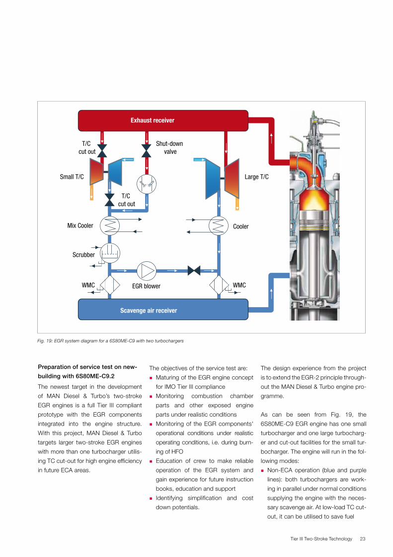
Fig. 19: EGR system diagram for a 6S80ME-C9 with two turbochargers
The design experience from the project
is to extend the EGR-2 principle through-
out the MAN Diesel & Turbo engine pro-
gramme.
As can be seen from Fig. 19, the
6S80ME-C9 EGR engine has one small
turbocharger and one large turbocharg-
er and cut-out facilities for the small tur-
bocharger. The engine will run in the fol-
lowing modes:
� Non-ECA operation (blue and purple
lines): both turbochargers are work-
ing in parallel under normal conditions
supplying the engine with the neces-
sary scavenge air. At low-load TC cut-
out, it can be utilised to save fuel
Tier III Two-Stroke Technology24
� ECA operation – Tier III (blue and
green lines): the small turbocharger is
cut out to compensate the reduced
exhaust gas amount, and the EGR
blower is running to supply exhaust
gas into the scavenge air receiver.
The pre-scrubber and scrubber
clean the EGR before the exhaust
gas enters the scavenge air receiver.
The EGR cooler has a double func-
tion and acts as an EGR cooler in
this mode and as a normal charge air
cooler in non-ECA mode.
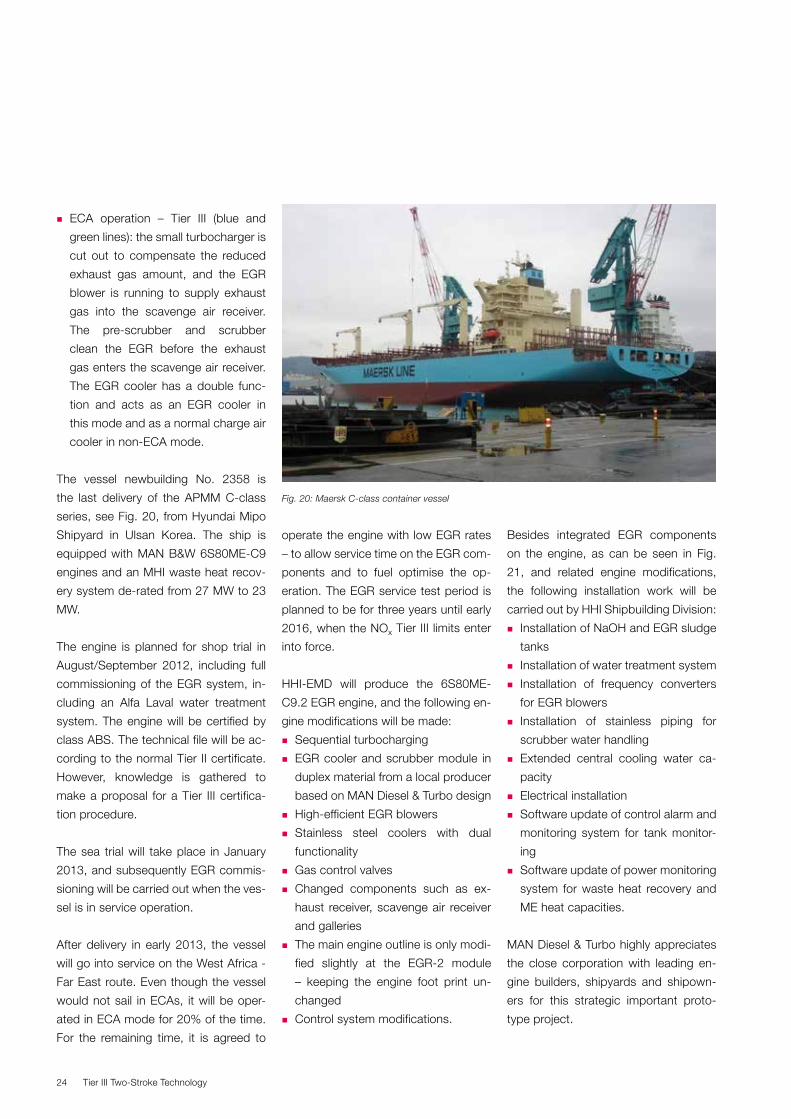
The vessel newbuilding No. 2358 is
the last delivery of the APMM C-class
series, see Fig. 20, from Hyundai Mipo
Shipyard in Ulsan Korea. The ship is
equipped with MAN B&W 6S80ME-C9
engines and an MHI waste heat recov-
ery system de-rated from 27 MW to 23
MW.
The engine is planned for shop trial in
August/September 2012, including full
commissioning of the EGR system, in-
cluding an Alfa Laval water treatment
system. The engine will be certified by
class ABS. The technical file will be ac-
cording to the normal Tier II certificate.
However, knowledge is gathered to
make a proposal for a Tier III certifica-
tion procedure.
The sea trial will take place in January
2013, and subsequently EGR commis-
sioning will be carried out when the ves-
sel is in service operation.
After delivery in early 2013, the vessel
will go into service on the West Africa -
Far East route. Even though the vessel
would not sail in ECAs, it will be oper-
ated in ECA mode for 20% of the time.
For the remaining time, it is agreed to
operate the engine with low EGR rates
– to allow service time on the EGR com-
ponents and to fuel optimise the op-
eration. The EGR service test period is
planned to be for three years until early
2016, when the NOx Tier III limits enter
into force.
HHI-EMD will produce the 6S80ME-
C9.2 EGR engine, and the following en-
gine modifications will be made:
� Sequential turbocharging
� EGR cooler and scrubber module in
duplex material from a local producer
based on MAN Diesel & Turbo design
� High-efficient EGR blowers
� Stainless steel coolers with dual
functionality
� Gas control valves
� Changed components such as ex-
haust receiver, scavenge air receiver
and galleries
� The main engine outline is only modi-
fied slightly at the EGR-2 module
– keeping the engine foot print un-
changed
� Control system modifications.
Besides integrated EGR components
on the engine, as can be seen in Fig.
21, and related engine modifications,
the following installation work will be
carried out by HHI Shipbuilding Division:
� Installation of NaOH and EGR sludge
tanks
� Installation of water treatment system
� Installation of frequency converters
for EGR blowers
� Installation of stainless piping for
scrubber water handling
� Extended central cooling water ca-
pacity
� Electrical installation
� Software update of control alarm and
monitoring system for tank monitor-
ing
� Software update of power monitoring
system for waste heat recovery and
ME heat capacities.
MAN Diesel & Turbo highly appreciates
the close corporation with leading en-
gine builders, shipyards and shipown-
ers for this strategic important proto-
type project.
Fig. 20: Maersk C-class container vessel
Tier III Two-Stroke Technology 25
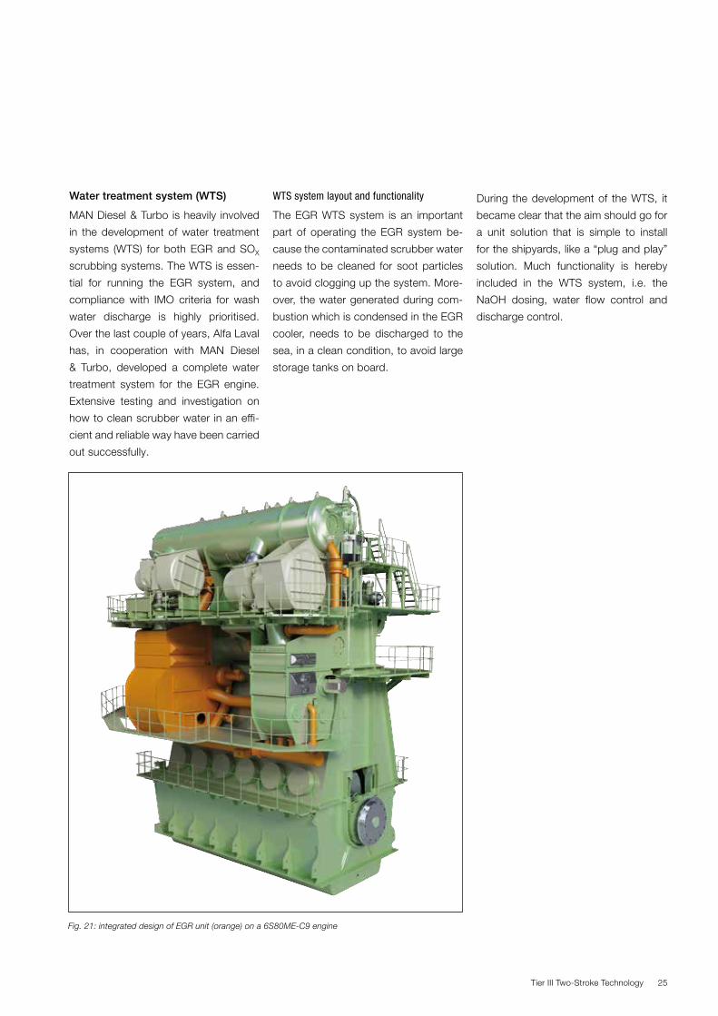
Fig. 21: integrated design of EGR unit (orange) on a 6S80ME-C9 engine
Water treatment system (WTS)
MAN Diesel & Turbo is heavily involved
in the development of water treatment
systems (WTS) for both EGR and SOX
scrubbing systems. The WTS is essen-
tial for running the EGR system, and
compliance with IMO criteria for wash
water discharge is highly prioritised.
Over the last couple of years, Alfa Laval
has, in cooperation with MAN Diesel
& Turbo, developed a complete water
treatment system for the EGR engine.
Extensive testing and investigation on
how to clean scrubber water in an effi-
cient and reliable way have been carried
out successfully.
WTS system layout and functionality
The EGR WTS system is an important
part of operating the EGR system be-
cause the contaminated scrubber water
needs to be cleaned for soot particles
to avoid clogging up the system. More-
over, the water generated during com-
bustion which is condensed in the EGR
cooler, needs to be discharged to the
sea, in a clean condition, to avoid large
storage tanks on board.
During the development of the WTS, it
became clear that the aim should go for
a unit solution that is simple to install
for the shipyards, like a “plug and play”
solution. Much functionality is hereby
included in the WTS system, i.e. the
NaOH dosing, water flow control and
discharge control.
Tier III Two-Stroke Technology26
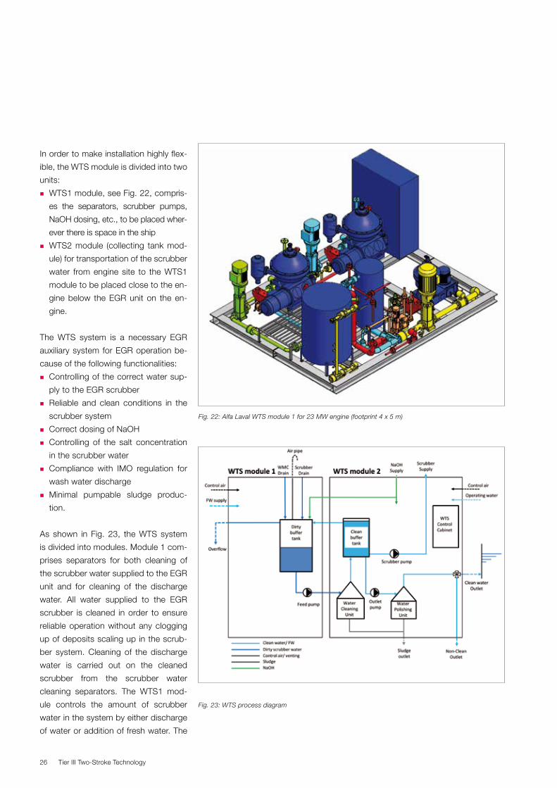
In order to make installation highly flex-
ible, the WTS module is divided into two
units:
� WTS1 module, see Fig. 22, compris-
es the separators, scrubber pumps,
NaOH dosing, etc., to be placed wher-
ever there is space in the ship
� WTS2 module (collecting tank mod-
ule) for transportation of the scrubber
water from engine site to the WTS1
module to be placed close to the en-
gine below the EGR unit on the en-
gine.
The WTS system is a necessary EGR
auxiliary system for EGR operation be-
cause of the following functionalities:
� Controlling of the correct water sup-
ply to the EGR scrubber
� Reliable and clean conditions in the
scrubber system
� Correct dosing of NaOH
� Controlling of the salt concentration
in the scrubber water
� Compliance with IMO regulation for
wash water discharge
� Minimal pumpable sludge produc-
tion.
As shown in Fig. 23, the WTS system
is divided into modules. Module 1 com-
prises separators for both cleaning of
the scrubber water supplied to the EGR
unit and for cleaning of the discharge
water. All water supplied to the EGR
scrubber is cleaned in order to ensure
reliable operation without any clogging
up of deposits scaling up in the scrub-
ber system. Cleaning of the discharge
water is carried out on the cleaned
scrubber from the scrubber water
cleaning separators. The WTS1 mod-
ule controls the amount of scrubber
water in the system by either discharge
of water or addition of fresh water. The
Fig. 23: WTS process diagram
Fig. 22: Alfa Laval WTS module 1 for 23 MW engine (footprint 4 x 5 m)
Tier III Two-Stroke Technology 27
WTS system ensures compliance with
IMO wash water criteria in all operation
cases.
The following parameters will define the
engine requirements to the WTS sys-
tem:
� Inlet scrubber water flow
� Inlet scrubber water pressure
� Inlet scrubber water temperature
� Quality of inlet scrubber water
- pH value
- salt concentration
- solids fraction
� Draining capacity.
The current development is aiming at
defining all necessary specific values for
the above-mentioned parameters.
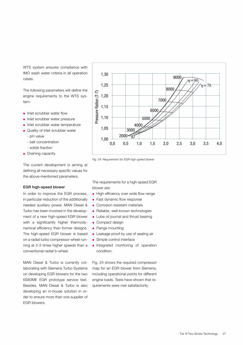
EGR high-speed blower
In order to improve the EGR process,
in particular reduction of the additionally
needed auxiliary power, MAN Diesel &
Turbo has been involved in the develop-
ment of a new high-speed EGR blower
with a significantly higher thermody-
namical efficiency than former designs.
The high-speed EGR blower is based
on a radial turbo compressor wheel run-
ning at 2-3 times higher speeds than a
conventional radial b-wheel.
MAN Diesel & Turbo is currently col-
laborating with Siemens Turbo Systems
on developing EGR blowers for the two
6S80ME EGR prototype service test.
Besides, MAN Diesel & Turbo is also
developing an in-house solution in or-
der to ensure more than one supplier of
EGR blowers.
1,30
1,25
1,20
1,15
1,10
1,00
1,05
Pres
sure
Rat
ion
(T-T
)
0,0 0,5 1,0 1,5 2,0 2,5 3,0 3,5 4,0
20003000
4000
5000
6000
7000
8000
9000
η=78η=80
87
Fig. 24: Requirement for EGR high-speed blower.
The requirements for a high-speed EGR
blower are:
� High efficiency over wide flow range
� Fast dynamic flow response
� Corrosion resistant materials
� Reliable, well-known technologies
� Lube oil journal and thrust bearing
� Compact design
� Flange mounting
� Leakage proof by use of sealing air
� Simple control interface
� Integrated monitoring of operation
condition.
Fig. 24 shows the required compressor
map for an EGR blower from Siemens,
including operational points for different
engine loads. Tests have shown that re-
quirements were met satisfactorily.
Tier III Two-Stroke Technology28
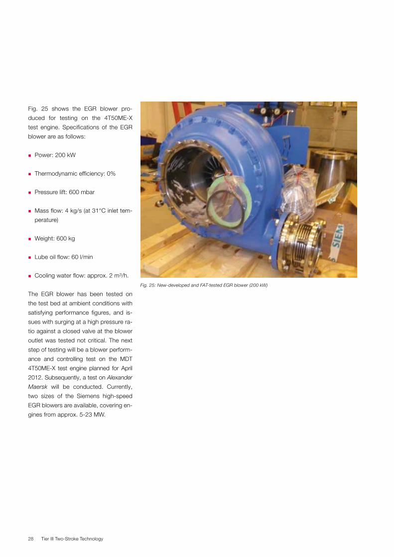
Fig. 25 shows the EGR blower pro-
duced for testing on the 4T50ME-X
test engine. Specifications of the EGR
blower are as follows:
� Power: 200 kW
� Thermodynamic efficiency: 0%
� Pressure lift: 600 mbar
� Mass flow: 4 kg/s (at 31°C inlet tem-
perature)
� Weight: 600 kg
� Lube oil flow: 60 l/min
� Cooling water flow: approx. 2 m3/h.
The EGR blower has been tested on
the test bed at ambient conditions with
satisfying performance figures, and is-
sues with surging at a high pressure ra-
tio against a closed valve at the blower
outlet was tested not critical. The next
step of testing will be a blower perform-
ance and controlling test on the MDT
4T50ME-X test engine planned for April
2012. Subsequently, a test on Alexander
Maersk will be conducted. Currently,
two sizes of the Siemens high-speed
EGR blowers are available, covering en-
gines from approx. 5-23 MW.
Fig. 25: New-developed and FAT-tested EGR blower (200 kW)
Tier III Two-Stroke Technology 29
Conclusion
As can be seen from the above, the
EGR application on two-stroke MAN
B&W engines has, over the last decade,
developed from a basic idea on how to
reduce NOx emissions to a dedicated
design, suitable for application on the
engine in standard configuration.
The development process has ensured
dedicated development of:
� Water spraying systems for pre-cool-
ing of exhaust gas
� Wet coolers capable of withstanding
SO2, SO3
and H2SO4 condensation
� Scrubbers with very high SO2 and
particulate emission removal capacity
� Compact high-speed and high-effi-
ciency EGR blowers
� Water treatment systems capable
of removing particulate matter ef-
ficiently, and clean water to suitable
discharge level
� Control systems capable of securing
simple push-button operation of the
EGR system
� Control strategies securing optimal
engine performance in both Tier II ar-
eas and in Tier III ECA areas.
This makes MAN Diesel & Turbo con-
fident that the EGR system application
will be available in due time before 2016
for the complete engine range.

Tier III Two-Stroke Technology30

Tier III Two-Stroke Technology 31

Tier III Two-Stroke Technology32

Tier III Two-Stroke Technology 33

Tier III Two-Stroke Technology34


MAN Diesel & TurboTeglholmsgade 412450 Copenhagen SV, DenmarkPhone +45 33 85 11 00Fax +45 33 85 10 [email protected]
MAN Diesel & Turbo – a member of the MAN Group
All data provided in this document is non-binding. This data serves informational purposes only and is especially not guaranteed in any way. Depending on the subsequent specific individual projects, the relevant data may be subject to changes and will be assessed and determined individually for each project. This will depend on the particular characteristics of each individual project, especially specific site and operational conditions. Copyright © MAN Diesel & Turbo. 5510-0125-00ppr Aug 2012 Printed in Denmark