Embed Size (px)
Citation preview
Two Approaches to Radar-Based Moving ObjectDetection
S, tefan SaftescuDepartment of Engineering Science
University of Oxford
Dominic Zeng WangMobile Robotics Group
University of Oxford
Ingmar PosnerMobile Robotics Group
University of Oxford
Abstract—We present a new segmentation-based approach fordetecting dynamic obstacles in radar scans. Instead of relying ontracking to determine whether an object is moving, we thresholdframe-difference data and obtain dynamic objects directly. Wecompare this with an SVM classifier trained on the same frame-difference data and show that segmentation performs better.
I. INTRODUCTION
Autonomous navigation of a mobile robot in crowded urbanenvironments is a challenging problem that requires a goodmodel of the surroundings. In particular, a pedestrian roboticplatform needs to detect far-away, high-speed obstacles whencrossing streets or in similar scenarios. In this paper we presenttwo approaches for detecting moving objects using a radarmounted on a stationary platform. Our motivation is to achievesafe interaction between a pedestrian mobile platform andother traffic participants.
Compared to other sensors, radar is much less affectedby environmental factors such as illumination and weatherconditions. In addition, compared to laser scanners, it hasa longer range and provides multiple returns per azimuth.However, radar scans are much noisier and many surfaces cancause reflections and ghosting (see Figure 1). Land-based radarsystems also suffer from ground backscatter, which accentuatesnoise.
For our experiments, we use a Navtech CTS350-X radar,detailed in Table I mounted on the EUROPA2 platform.EUROPA2, the follow-up to EUROPA, is a research projectthat has the aim to boost development of technologies for life-long, autonomous urban navigation.
TABLE I. TECHNICAL DETAILS OF THE NAVTECH CTS350-X RADAR
Range bins 2000Range resolution 25cmBeamwidth, azimuth 2◦
Beamwidth, elevation 2◦ or spreadbeamMeasurement rate 1600 per secondScan rotation rate 4 rpsField of view 360◦
II. RELATED WORK
The sensor we use is similar to forward-looking sonars inmany respects, including noise and beam models, so a lot ofthe relevant related work has been done with sonars.
For example, [1] describes a technique for detecting objectsthrough segmentation of forward-looking sonar scans. The
segmentation is done using double-thresholding to first selectthe most visible parts of targets and then determine the size.This is done in the context of an autonomous underwatervehicle (AUV), where clutter from non-relevant targets isminimal. [2] uses a similar radar sensor to provide detectionsof objects from a vehicle driving on a motorway. In this work,radar detections are validated by a camera that is used toremove false positives. More recently, [3] proposed anothermethod for detecting and tracking objects with a forward-facing sonar mounted on an AUV. In contrast to [1], thethresholding used for segmenting frames is based on localstatistics.
III. APPROACH AND IMPLEMENTATION
A radar scan consists of 398 beams at fixed azimuthscovering 360◦. Each beam has 2000 uniformly spaced intensityreadings at different ranges. For our goal of dynamic objectdetection, we decided to keep the data in the native polarcoordinates: each scan is represented as a 2000×398 matrixof intensity values, where rows correspond to different rangesand columns to different azimuths. For tracking and planning,the detections can easily be mapped to Cartesian coordinates.
A mandatory step in processing radar scans is denoising.Radar and ultrasound readings generally suffer from corruptionwith multiplicative, speckle noise. Simple speckle-removingtechniques such as the Lee filter [4] only process homogeneous
Fig. 1. Examples of moving objects in frame-differences. Top-left: a carmoving away from the sensor. Bottom-left: a bus moving in the same directionas the car; notice that the local minimum and maximum are swapped. Right:a car (solid line) and its reflections (dashed lines).

areas, leaving a lot of speckle around edges. More advancedtechniques such as Speckle Reducing Anisotropic Diffusion[5] perform very well, but at very high computational cost.We have found that a 7×7 Gaussian smoothing filter followedby a 3×3 median filter is sufficient to remove most of thehigh-intensity noise in our data.
Since one of our main motivations is to allow a mobilepedestrian platform to safely cross a street in a crowded urbanenvironment, it’s reasonable to assume that the robot is movingrelatively slowly or is static. In this paper, we assume that ourplatform is stationary, so we can perform background removalthrough simple frame differencing.
After this initial pre-processing, we explore two approachesfor detecting dynamical objects: one is using double-thresholdsegmentation, the other is training a Support Vector Machineto detect moving objects.
For the remainder of the paper, we will describe theseapproaches, evaluate and compare them.
A. Segmentation
The segmentation approach applies the work that [1] havedone with forward-facing sonar to 360◦ radar scans.
The novelty in our approach is that we work with framedifferences in which moving objects create two peaks — a(positive) local maximum and a (negative) local minimum.These often correspond to where the object is in the currentframe and where the object was in the previous frame, respec-tively. However, this is not always the case; for example, largemetallic objects such as buses can cause these peaks to bereversed (see Figure 1). We therefore consider both positiveand negative peaks to be an indication of dynamic objectsand perform segmentation on the absolute value of frame-differences.
To find the moving objects in the image, we first applya high threshold (60% of the maximum intensity value) toobtain the most visible parts of the objects. We then applya low threshold (25% of the maximum value) and only keepthe points connected to the high peaks from the previous step(using 8-connectivity). An illustration of this technique appliedto a 1-D signal can be seen in Figure 3.
High threshold
Low threshold
Fig. 3. An example of double-thresholding for a 1-D signal. After [1].
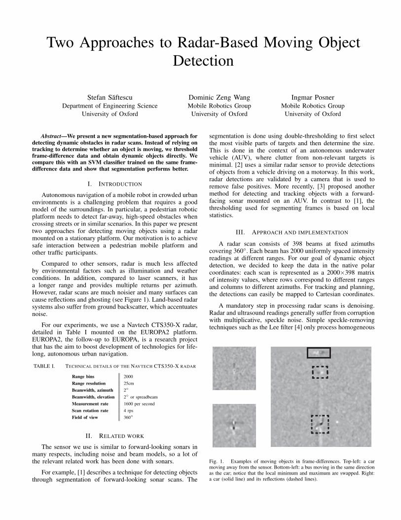
This results in two components for each moving object,corresponding to the positive and negative peaks previouslymentioned. As an important last step to avoid duplicate detec-tions, we to join these components by applying morphologicaldilation, obtaining the segmentation of the radar scan (Figure2c).
B. Support Vector Machine detection
Another approach we have explored is detection using aSupport Vector Machine (SVM) [6], [7] with the radial basisfunction kernel (σ = 33.05) given by:
K(x,x′) = exp
(−||x− x′||2
2σ2
).
The training set consists of 200 consecutive, manually-labelled frames that contain 1658 positive labels of dynamicobjects and 657 negative labels. The training is done using thesvmtrain function in Matlab’s Statistics and Machine LearningToolbox on HOG features [8].
IV. EVALUATION
We evaluate the performance of our approaches on 56manually labelled frames that contain 497 dynamical objects.We try to follow the same evaluation metrics as the onespresented in [9].
Recall0 0.2 0.4 0.6 0.8 1
Prec
isio
n
0
0.1
0.2
0.3
0.4
0.5
0.6
0.7
0.8
0.9
1SegmentationSVM
Fig. 4. Comparison between segmentation and SVM detection approaches.For segmentation, we vary the lower threshold between 20% and 50% and thehigher threshold between 50% and 90% and plot the resulting PR points. Formany threshold settings, segmentation proves better than the machine learningapproach.
To compute precision and recall values, we first find thebounding boxes (with 5px padding to match the padding of theground-truth labels) of the connected components that resultfrom segmentation. For each of the frames in the test set, wematch the bounding boxes to the ground-truth labels:
1) We compute the overlaps between a predicted bound-ing box Bp and a ground-truth bounding box Bgt
using the standard overlap measure: coefficient:
overlap(Bp, Bgt) =area(Bp ∩Bgt)
area(Bp ∪Bgt).
2) For each predicted detection (in no particular orderfor segmentation and in descending order of predic-tion score for SVM) we assign the best matching
(a)
Azimuth (°)45 90 135
Ran
ge (m
)50
100
150
200
250
300
350
400
450
500
(b)
Azimuth (°)45 90 135
Ran
ge (m
)
50
100
150
200
250
300
350
400
450
500
(c)
Azimuth (°)45 90 135
Ran
ge (m
)
50
100
150
200
250
300
350
400
450
500
Fig. 2. Different stages of the segmentation pipeline. (a) raw data in matrix format; (b) smoothed frame from (a) minus previous smoothed frame; (c)segmentation results.
ground truth label with overlap greater than 50% thathas not been previously assigned.
In this way, a detection is matched to at most one ground-truth label and vice-versa. It follows that duplicate detectionsof the same object are marked as false positives.
V. CONCLUSION AND FUTURE WORK
We have presented a new method for detecting movingobjects in radar scans that does not rely on tracking. We havealso shown that it performs better than a baseline classifier.
There are still problems that need to be explored beforeeither of the two approaches can be deployed. Both methodscan benefit from tracking to validate detections. As the absoluteintensity of detections decreases with range, tracking couldalso drive an adaptive thresholding method for segmentation.The detector presented in this paper was trained with fewexamples, so techniques such as hard negative mining could beemployed to gather additional training data. Finally, we needto explore whether either approach can be extended to movingplatforms, in the presence of good odometry data.
REFERENCES
[1] Y. Petillot, I. T. Ruiz, and D. M. Lane, “Underwater vehicle obstacleavoidance and path planning using a muli-beam forward looking sonar,”IEEE J. Ocean. Eng., vol. 26, no. 2, pp. 240–251, 2001.
[2] G. Alessandretti, A. Broggi, and P. Cerri, “Vehicle and guard raildetection using radar and vision data fusion,” IEEE Trans. Intell. Transp.Syst., vol. 8, no. 1, pp. 95–105, 2007.
[3] I. Quidu, L. Jaulin, A. Bertholom, and Y. Dupas, “Robust multitargettracking in forward-looking sonar image sequences using navigationaldata,” IEEE J. Ocean. Eng., vol. 37, no. 3, pp. 417–430, 2012.
[4] J. S. Lee, “Digital image enhancement and noise filtering by use of localstatistics.” IEEE Trans. Pattern Anal. Mach. Intell., vol. 2, no. 2, pp.165–168, 1980.
[5] Y. Yu and S. Acton, “Speckle Reducing Anisotropic Diffusion,” IEEETrans. Image Process., vol. 2, no. 11, pp. 1260–1270, 2002.
[6] V. Vapnik and a. Lerner, “Pattern recognition using generalized portraitmethod,” Automation and remote control, vol. 24, pp. 774–780, 1963.
[7] B. E. Boser, I. M. Guyon, and V. N. Vapnik, “A Training Algorithmfor Optimal Margin Classifiers,” Proceedings of the 5th Annual ACMWorkshop on Computational Learning Theory, pp. 144–152, 1992.
[8] N. Dalal and B. Triggs, “Histograms of oriented gradients for humandetection,” Proceedings of the 2005 IEEE Computer Society Conferenceon Computer Vision and Pattern Recognition, pp. 886–893, 2005.
[9] M. Everingham, L. Van Gool, C. K. I. Williams, J. Winn, and A. Zisser-man, “The pascal visual object classes (VOC) challenge,” Int. J. Comp.Vis., vol. 88, no. 2, pp. 303–338, 2010.