Embed Size (px)
Citation preview

World Precision Instruments
OXY MICRO Fiber Optic Oxygen Measurement System
for Oxygen Microsensors
ro fiber optic pHINSTRUCTION MANUAL
PC-controlled one-channel fiber optic oxygen meter for oxygen microsensors; excitation wavelength of 505 nm; quartz-quartz glass fibers of less than 150 µm diameter connected by ST-fiber connectors. Also available with two 12-bit analog outputs and external trigger input.
ww
w.w
piin
c.co
m


OXY MICRO Specification:
Micro fiber optic oxygen transmitter for use with oxygen microsensors Software version:
OxyMicro (Version 7.0.0) Document filename: IM_OXY-MICRO-AOT_dv2 All rights reserved. No parts of this work may be reproduced in any form or by any means - graphic, electronic, or mechanical, including photocopying, recording, taping, or information storage and retrieval systems - without the written permission of the publisher. Products that are referred to in this document may be either trademarks and/or registered trademarks of the respective owners. The publisher and the author make no claim to these trademarks. While every precaution has been taken in the preparation of this document, the publisher and the author assume no responsibility for errors or omissions, or for damages resulting from the use of information contained in this document or from the use of programs and source code that may accompany it. In no event shall the publisher and the author be liable for any loss of profit or any other commercial damage caused or alleged to have been caused directly or indirectly by this document. Specifications may change without prior notice.
World Precision Instruments, Inc.USA: International Trade Center, 175 Sarasota Center Boulevard, Sarasota FL 34240-9258 USA
Tel: 941-371-1003 • Fax: 941-377-5428 • E-mail: [email protected] • Internet: http://www.wpiinc.com
Germany: Zossener Str. 55, 10961 Berlin, Germany . Tel: 030-6188845 . Fax: 030-6188670 . E-mail: [email protected] & Hong Kong: WPI Shanghai Trading Co., Ltd. . Tel: +86 688 85517 . E-mail: [email protected]
UK: 1 Hunting Gate, Hitchin, Hertfordshire SG4 OTJ . Tel: 44 (0) 1462 424700 . Fax: 44(0) 1462 424701 . E-mail: [email protected]

Table of Contents 1 Preface ......................................................................................................................... 3
2 Description of the OXY MICRO Transmitter ............................................................. 4 2.1 Scope of Delivery ....................................................................................................... 5 2.2 Front Panel ................................................................................................................. 6 2.3 Rear Panel .................................................................................................................. 6
3 Installation ................................................................................................................... 8 3.1 Set-up .......................................................................................................................... 8 3.2 Software Installation .................................................................................................. 9 3.3 USB Serial Driver Installation ................................................................................... 9
4 Operation ................................................................................................................... 12 4.1 Adjustment of Regional Settings of the Operating System ................................. 12 4.2 Configuration of COM Port ..................................................................................... 14 4.3 Starting the Device .................................................................................................. 16 4.4 Calibration ................................................................................................................ 19 4.4.1 Calibration with Temperature Sensor .................................................................... 20 4.4.2 Calibration without Temperature Sensor ............................................................... 22 4.4.3 Manual Calibration* ................................................................................................. 24 4.5 Measurement ............................................................................................................ 26 4.5.1 Control Bar ............................................................................................................... 28 4.5.2 Graphical Display ..................................................................................................... 30 4.6 Subsequent Data Handling ..................................................................................... 32 4.7 Analog Output .......................................................................................................... 35 4.8 LED Intensity ............................................................................................................ 36 4.9 Software Menu Structure ........................................................................................ 37
5 Technical Data ........................................................................................................... 38 5.1 Specifications........................................................................................................... 38 5.2 Analog Output and External Trigger ...................................................................... 41
6 Operational Notes ..................................................................................................... 43 6.1 Optical Output .......................................................................................................... 43 6.2 Temperature Compensation ................................................................................... 43 6.3 Warm-Up Time.......................................................................................................... 43 6.4 Power Adapter.......................................................................................................... 43 6.5 Analog Outputs ........................................................................................................ 43 6.6 RS232 Interface / USB Interface .............................................................................. 43 6.7 Maintenance ............................................................................................................. 43 6.8 Service ...................................................................................................................... 44
7 CE and FCC Conformity ........................................................................................... 45
8 Concluding Remarks ................................................................................................ 46


3
OXY MICRO Preface
1 Preface You have chosen a new, innovative technology for measuring oxygen. The OXY MICRO is a compact, easy to transport and completely PC-controlled micro fiber optic oxygen transmitter. The data evaluation is PC supported as well. The OXY MICRO was developed especially for fiber optic oxygen microsensors. It is based on a novel technology, which creates very stable, internally referenced measured values. This allows a more flexible use of oxygen microsensors in various fields of interest. Chemical optical oxygen microsensors (also called optrodes) have several important features:
They are small.
Their signal does not depend on the flow rate of the sample.
They allow measurements with high spatial resolution whenever this is required.
Therefore, they are ideally suited for the examination of small sample volumes. A set of different oxygen microsensors is available to make sure you have the sensor which matches your application. Please feel free to contact our service team to find the best solution for your application. Your WPI Team PLEASE READ THE FOLLOWING INSTRUCTIONS CAREFULLY BEFORE WORKING WITH THIS DEVICE.

4
OXY MICRO Description of the OXY MICRO
2 Description of the OXY MICRO Transmitter
The OXY MICRO is a precise single channel micro fiber optic oxygen transmitter with temperature compensation. It is designed for very small fiber optic oxygen microsensors (tip diameter < 50 µm) with sensor coating type PSt1 (limit of detection 0.05 % oxygen, 20 ppb dissolved oxygen). The small outer dimensions and low power consumption make it suitable for portable use. For operation, a PC / notebook is required. The OXY MICRO is controlled using a comfortable software, which also saves and visualizes the measured values.
The OXY MICRO has a dual 12 bit analog output, and an external trigger input to be connected to a data logger. The analog outputs are programmable to deliver oxygen, temperature or the raw values (phase or amplitude). The data are retrieved via PC / notebook and USB (alternatively RS232) (digital) or using the external trigger input (analog). Features:
High precision
Portable (battery power optional)
Analog / Digital data output (on request)
Temperature compensation
Fig. 1 OXY MICRO, micro fiber optic oxygen transmitter for use with oxygen microsensors

5
OXY MICRO Description of the OXY MICRO
2.1 Scope of Delivery
OXY MICRO, micro fiber optic oxygen transmitter
Software OxyMicro - V7.0.0 (CD)
USB serial driver (CD)
USB cable
RS232 cable
Power supply (100 - 240 VAC, 18 VDC)
Temperature sensor PT 1000
Additionally required equipment (not supplied):
Oxygen-sensitive chemical optical microsensor
You can find microsensors – mounted into different types of housings – on
www.wpiinc.com
PC / Notebook for comfortable data recording and configuration
System requirements:
Microsoft® Windows® XP / VistaTM or Microsoft® Windows® 7; Processor power
according to minimum requirements of the respective operating system
Fig. 2 Case with all delivered equipment

6
OXY MICRO Description of the OXY MICRO
2.2 Front Panel
The front panel is equipped with a connector for the fiber optic microsensor, a connector for the temperature sensor, a control LED and an ON / OFF switch.
ELEMENT DESCRIPTION FUNCTION
POWER ON / OFF switch
Control LED
Switches the device ON and OFF.
red: device off green: device on orange: standby
OXYGEN SENSOR
ST fiber connector Connect the fiber optic microsensor here.
TEMP Connector for PT 1000 temperature sensor
Connect the PT 1000 temperature sensor for temperature compensated measurements here.
2.3 Rear Panel
Two standard BNC connectors are added for analog output channels 1 and 2, another one for external trigger input. The electrical specifications of all rear panel connectors are given in chapter 5 “Technical Data”. Please follow these notes to avoid mistakes.
Fig. 3 Transmitter front panel
Fig. 4 Transmitter rear panel

7
OXY MICRO Description of the OXY MICRO
ELEMENT DESCRIPTION FUNCTION
12 VDC Line adapter for power supply
Connect the power supply cable. Use the provided parts only.
RS232 USB / RS232 interface (male)
Connect the device with a USB or RS232 data cable to your PC / notebook. Use the provided parts only.
CH 1 Analog out (channel 1)
Connect the device with external devices, e.g. a data logger.
CH 2 Analog out (channel 2)
Connect the device with external devices, e.g. a data logger.
EXT TRIG External trigger input
Connect the device with external devices, e.g. a data logger with a trigger output, pulse generator.

8
OXY MICRO Installation
3 Installation 3.1 Set-up
A typical set-up is shown in Fig. 5. An oxygen microsensor is connected via an optical fiber to the transmitter which is connected via a serial COM port to a PC. The OxyMicro - V7.0.0 software is compatible with Microsoft® Windows® XP / VistaTM and Microsoft® Windows® 7.
Remove the rubber cap from the optical sensor connector (ST connector) and keep the cap. After measurements or for storing the transmitter the rubber cap should be put back on to keep the optical sensor connector clean.
! It is recommended to clean the ST connector with a dust free cleaning wipe or a cleaning implement for ST connectors before the measurement. Make sure to insert the cleaning implement into the inner part of the connector; then turn it three or four times.
Remove the protective cap from the male plug on the optical fiber and insert it in the ST connector of the OXY MICRO. The ST plug has to be inserted and slightly turned clockwise to fasten it. Be careful not to snap off the optical fiber; best hold the fiber between forefinger and thumb at the bayonet lock of the male plug (see Fig. 6).
Fig. 5 Set-up for OXY MICRO

9
OXY MICRO Installation
There is a red mark on the temperature sensor connector of the OXY MICRO. The temperature sensor plug also has a red mark. Match those two marks before inserting the temperature sensor plug into the connector on the transmitter front panel; else the plug might get damaged.
3.2 Software Installation
The software is working with English and German regional settings. Please change your setting to one of these settings before installing the software. 1. Please close all other applications as they may interfere with the software. 2. Insert the supplied CD-ROM into the respective drive. 3. If no dialog opens automatically, use the explorer to open the file menu on the CD. Copy
the file “OxyMicro_v7.0.0.exe” to a folder on your PC (e.g. C:/OXY MICRO/…) and create a shortcut to your desktop so you are able to start the software quickly.
4. Start the software by double clicking the symbol for the “OxyMicro_v7.0.0.exe” file.
3.3 USB Serial Driver Installation
The USB-RS232-RJ 4/4 requires
At least one available USB port
Windows XP / Vista / 7
Connect the USB cable to the PC / notebook and insert the delivered driver CD.
Fig. 6 Attaching the oxygen microsensor to the connector on the transmitter

10
OXY MICRO Installation
The Found New Hardware Wizard will launch automatically. Select No, not this time from the options and click Next.
Select Install from a list or specific location (Advanced); then click Next.
Select Search for the best driver in these locations and go to Search for removable media (floppy, CD-ROM…). Click Next to proceed.
Fig. 7 Found New Hardware Wizard
Fig. 8 Found New Hardware Wizard

11
OXY MICRO Installation
Then Windows will copy the required driver files. Windows should then display a message indicating that the installation was successful. Click Finish to complete the installation.
Fig. 9 Found New Hardware Wizard

12
OXY MICRO Operation
4 Operation 4.1 Adjustment of Regional Settings of the Operating
System
The software is working with English and German regional settings. To change the regional settings on your PC press Start and go to the Control Panel. Choose Regional and Language Options.
Select the Regional Options tab (e.g. English (United States)) and click Customize.
Fig. 11 Regional and Language Options window
Fig. 10 Control Panel – Classic View

13
OXY MICRO Operation
A window opens; select the Numbers tab and choose the dot `.´ in the Decimal Symbol drop down menu. In the drop down menu Digit grouping symbol you have to choose space ` ´. Then press Apply and OK.
Click Customize again and go to the Date tab now. In the drop down menu Short date format you have to select `dd.MM.yy´ and choose the dot `.´ in Date separator. Again press Apply and OK.
Press OK in the Regional and Language Options window, and you have finished adjusting the regional settings.
Fig. 12 Customize Regional Options window – Numbers tab
Fig. 13 Customize Regional Options window – Date tab

14
OXY MICRO Operation
4.2 Configuration of COM Port
To check which COM port is assigned to the USB cable press Start and go to the Control Panel. Select System. Select the Hardware tab in the System Properties window and click Device Manager.
You can find the USB serial Port under Ports (COM & LPT) (in the figure below this would be COM port 6 for example).
Fig. 14 System Properties window
Fig. 15 Device Manager – USB Serial Port selected

15
OXY MICRO Operation
! OXY MICRO only accepts COM port numbers that are < 10. In case the COM port
number is 10 or higher please change it to a port number < 10. To change the COM port number you open the Device Manager activate Port (COM & LPT) and double-click the USB-Serial Port. A window opens; select the Port Settings tab and click on Advanced.
Change the COM Port Number to a free port number < 10 and click OK.
You have to confirm the new port number by clicking OK; then you can close the device manager.
Fig. 16 USB Serial Port Properties – Port Settings tab
Fig. 17 Advanced Settings for COM Port window

16
OXY MICRO Operation
4.3 Starting the Device
1. Connect the OXY MICRO via the supplied USB cable to a serial COM port of your PC / notebook. (Alternatively, You can connect the OXY MICRO via the RS232 cable to a serial COM port of your PC / notebook. Tighten the cable with the screws on your PC / notebook.)
2. Connect the power supply. 3. Please close all other applications as they may interfere with the software. Start the
software OxyMicro - V7.0.0.
The software is scanning all COM ports available to detect and configure the connected OXY MICRO device.
Fig. 18 Initial Window - Software is scanning to detect the connected OXY MICRO device

17
OXY MICRO Operation
If the software is unable to detect the correct COM port, a message is displayed asking you to choose the right COM port.
With a right mouse click onto Com Port the dialog Select COM Port opens. Select the correct COM port in the drop-down menu and click the OK button.
! If no device is detected, please check all connections and proper installation of serial
COM ports.
Fig. 20 Select COM Port dialog
Fig. 19 Information dialog – choose the right COM port
18
OXY MICRO Operation
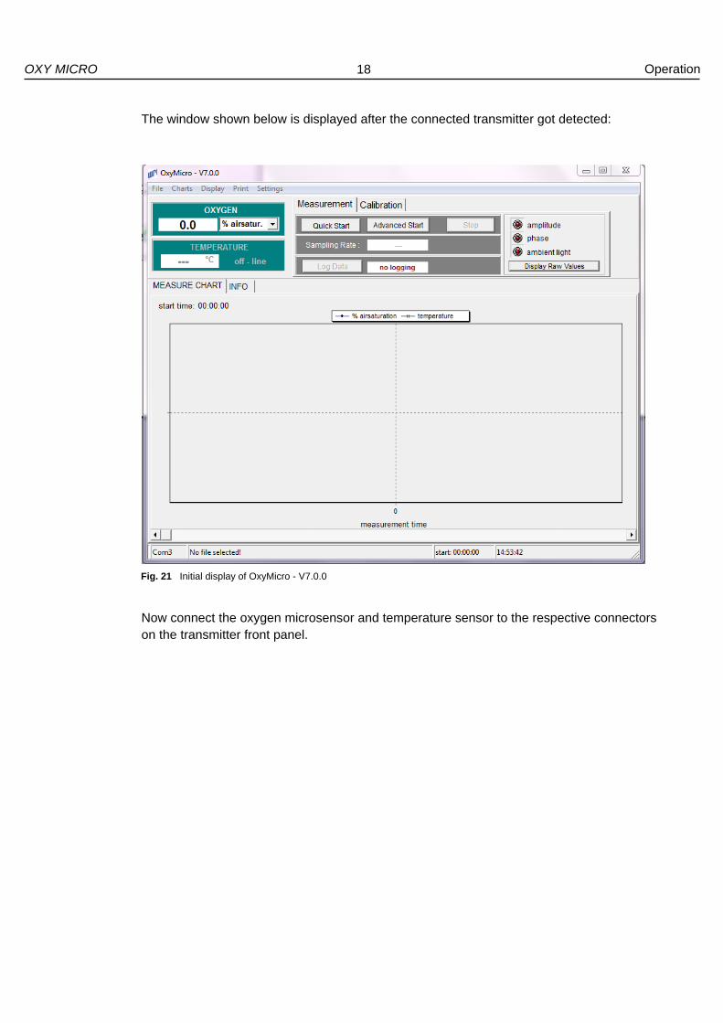
The window shown below is displayed after the connected transmitter got detected:
Now connect the oxygen microsensor and temperature sensor to the respective connectors on the transmitter front panel.
Fig. 21 Initial display of OxyMicro - V7.0.0

19
OXY MICRO Operation
4.4 Calibration
Prior to measurements you have to calibrate the oxygen microsensor. Click the Calibration tab in the upper middle screen.
There are three different calibration modes:
With the setting calibrate with temperature sensor the current raw phase values of
the oxygen microsensor are measured and stored. Temperature during calibration is
measured with the PT 1000 temperature sensor and saved. The temperature sensor
has to be in close vicinity to the oxygen microsensor or make sure that the
temperature at both oxygen and temperature sensor is the same.
With the setting calibrate without temp. sensor the current raw phase values of the
oxygen microsensor are measured and stored. The temperature value during
calibration is set manually in the software and stored. This option can be used, if the
temperature at the location of the oxygen microsensor is known.
With the setting calibrate manually the raw phase values of the oxygen microsensor
as well as the temperature values are set manually in the software. This option can be
used, if previously measured calibration values for the currently used oxygen
microsensor are available. You can find calibration data on the Final Inspection
Protocol delivered with your oxygen microsensor (see Fig. 32).
Please read the instruction manual of the respective oxygen sensor for more detailed information about calibration standards and sensor specifications.
Fig. 22 Calibration tab

20
OXY MICRO Operation
4.4.1 Calibration with Temperature Sensor
Clicking the cal. button next to calibrate with temperature sensor opens the respective Calibration Menu dialog:
1. Insert the current atmospheric pressure value. 2. Set the first calibration point (0 % air sat.).
Place the oxygen microsensor and temperature sensor in the medium for the first calibration point. At the bottom of the dialog the currently measured amplitude and phase value of the oxygen microsensor and the temperature are displayed. Watch the displayed phase value; wait for about 3 minutes until the phase angle is constant (the variation of the phase angle should be smaller than ± 0.1° and the variation of temperature smaller
than ± 0.1°C) and click the Store current value button to the right of the 1st point value. The transmitter stores amplitude, phase and temperature values.
Fig. 23 Dialog for calibration with temperature sensor
Fig. 24 Dialog for calibration with temperature sensor – storing the first calibration value
24681 57.28 25.4
24681 57.28 25.4

21
OXY MICRO Operation
A warning message is displayed saying this will overwrite the existing calibration values; hit Continue and the 1st point values will be updated.
3. Set the second calibration point (100 % air sat.). Place the oxygen microsensor and temperature sensor in the medium for the second calibration point. At the bottom of the dialog the currently measured amplitude and phase value of the oxygen microsensor and the temperature are displayed. Watch the displayed phase value; wait for about 3 minutes until the phase angle is constant (the variation of the phase angle should be smaller than ± 0.1° and the variation of temperature smaller
than ± 0.1°C) and click the Store current value button to the right of the 2nd point value. The transmitter stores amplitude, phase and temperature values.
A warning message is displayed saying this will overwrite the existing calibration values (see Fig. 25); hit Continue and the 2nd point values will be updated.
End the calibration process by clicking the Finish button. The calibration data are stored to the transmitter and the display in the INFO tab will be updated.
Fig. 25 Calibration message window
Fig. 26 Dialog for calibration with temperature sensor – storing the second calibration value
24681 57.28 25.4

22
OXY MICRO Operation
4.4.2 Calibration without Temperature Sensor
Clicking the cal. button next to calibrate without temperature sensor opens the respective Calibration Menu dialog:
1. Insert the current atmospheric pressure value. 2. Set the first calibration point (0 % air sat.).
Place the oxygen microsensor in the medium for the first calibration point. At the bottom of the dialog the currently measured amplitude and phase value of the oxygen microsensor are displayed. Set the current temperature at the oxygen microsensor by using the up and down arrows or typing in the temperature value. Watch the displayed phase value; wait for about 3 minutes until the phase angle is constant (the variation of the phase angle should be smaller than ± 0.1°) and click the Store current value button to the right of the 1st point value. The transmitter stores amplitude, phase and temperature values.
Fig. 27 Dialog for calibration without temperature sensor
Fig. 28 Dialog for calibration without temperature sensor – storing the first calibration value
27852 27.67
24681 57.28

23
OXY MICRO Operation
A warning message is displayed saying this will overwrite the existing calibration values; hit Continue and the 1st point values will be updated.
3. Set the second calibration point (100 % air sat.). Place the oxygen microsensor in the medium for the second calibration point. At the bottom of the dialog the currently measured amplitude and phase value of the oxygen microsensor are displayed. Set the current temperature at the oxygen microsensor by using the up and down arrows or typing in the temperature value. Watch the displayed phase value; wait for about 3 minutes until the phase angle is constant (the variation of the phase angle should be smaller than ± 0.1°) and click the Store current value button to the right of the 2nd point value. The transmitter stores amplitude, phase and temperature values.
A warning message is displayed saying this will overwrite the existing calibration values (see Fig. 29); hit Continue and the 2nd point values will be updated.
End the calibration process by clicking the Finish button. The calibration data are stored to the transmitter and the display in the INFO tab will be updated.
Fig. 29 Calibration message window
Fig. 30 Dialog for calibration without temperature sensor – storing the second calibration value
24681 24681 57.28

24
OXY MICRO Operation
4.4.3 Manual Calibration*
Clicking on manual will open the respective Calibration Menu dialog:
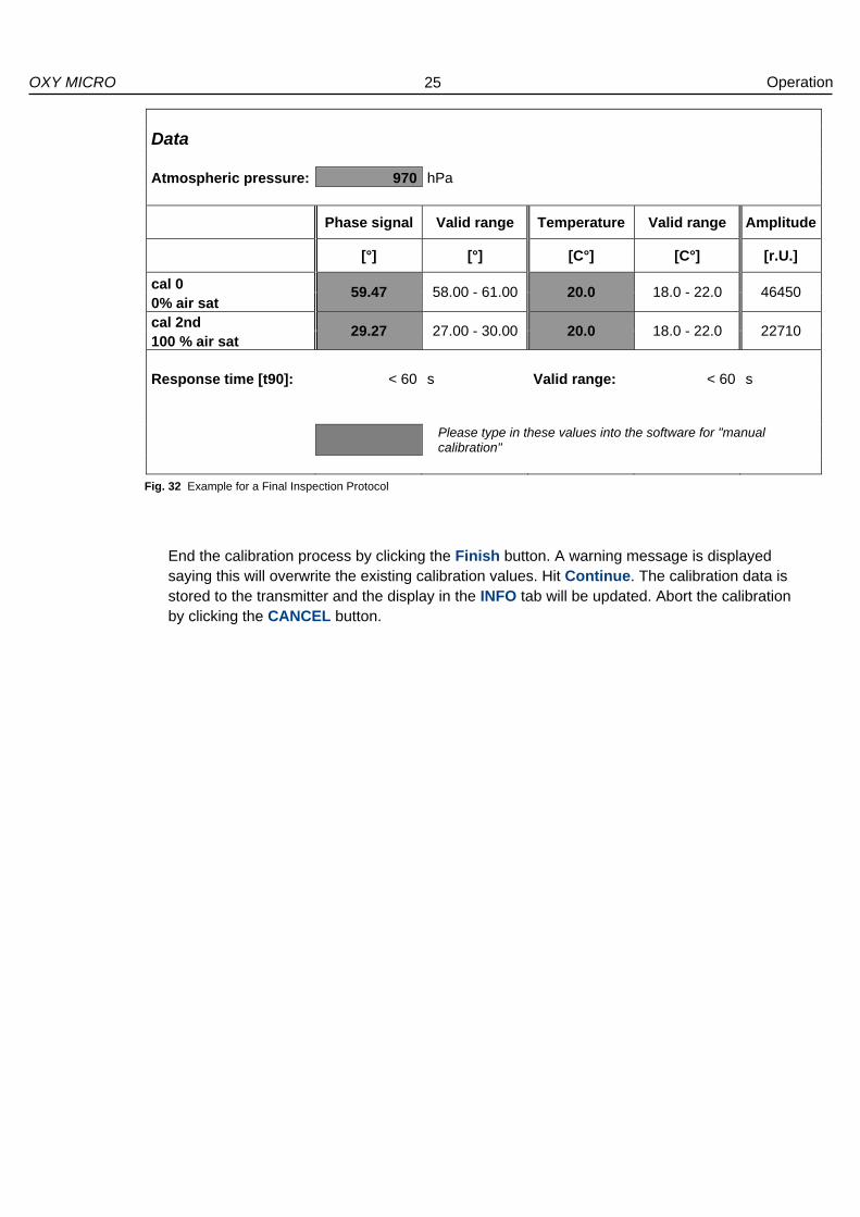
You can find calibration data on the Final Inspection Protocol delivered with your oxygen microsensor (see Fig. 32). Use the values in the grey highlighted boxes to fill in the Calibration Menu. If previously measured calibration values for the used oxygen sensor are available you can also use these values for the manual calibration.
1. Insert the atmospheric pressure at which the calibration data you are using were measured. (In case you are using the FIP data use the pressure value in the grey highlighted box.)
2. Select phase and temperature value for the first calibration point. 3. Select phase and temperature value for the second calibration point.
*Technical data relate to sensor specific calibration.
Fig. 31 Dialog for user defined calibration
25
OXY MICRO Operation
End the calibration process by clicking the Finish button. A warning message is displayed saying this will overwrite the existing calibration values. Hit Continue. The calibration data is stored to the transmitter and the display in the INFO tab will be updated. Abort the calibration by clicking the CANCEL button.
Data Atmospheric pressure: 970 hPa
Phase signal Valid range Temperature Valid range Amplitude
[°] [°] [C°] [C°] [r.U.]
cal 0 59.47 58.00 - 61.00 20.0 18.0 - 22.0 46450
0% air sat cal 2nd
29.27 27.00 - 30.00 20.0 18.0 - 22.0 22710 100 % air sat Response time [t90]: < 60 s Valid range: < 60 s
Please type in these values into the software for "manual calibration"
Fig. 32 Example for a Final Inspection Protocol

26
OXY MICRO Operation
4.5 Measurement
Press the Quick Start button to open the Measurement Assistant.
If no calibration has been performed or the software has been closed after calibration the following message showing the date of the last calibration is displayed:
Click Continue to go on with the measurement assistant or press New Calibration, which will get you back to the calibration menu.
Fig. 33 Quick Start button
Fig. 34 Measurement Assistant dialog showing the date of the last calibration

27
OXY MICRO Operation
Sampling Rate
Measurement frequencies from “fast sampling” up to 60 minutes can be selected. The speed in “fast sampling” mode is about 250 ms when no temperature sensor is connected and decreases to about 350 ms when connecting the temperature sensor or activating the analog output channels.
! The sensor shelf-life can be increased using a slower measuring mode; the effect of
photobleaching is reduced as the illumination light is switched off between sampling. Moreover a huge amount of data for long-time measurements can be avoided using a slower measuring mode.
Dynamic Averaging
When choosing a sampling rate of 1 sec. Dynamic Averaging can be selected. This defines the number of averaged measured values. The higher the running average, the longer the time (sampling time) used for averaging. With a higher running average value set (maximum 25 samples) a smoother measurement signal can be achieved. The default setting is 4.
Temperature Compensation
Select the temperature measurement mode for temperature compensated oxygen measurement. The following options can be selected:
Selecting off you have to set a constant temperature value. This option can be used, if
the temperature at the location of the oxygen microsensor is known and stays
constant throughout the measurement.
Selecting on the temperature value for temperature compensation of the oxygen
microsensor is measured with the supplied PT1000 temperature sensor. Make sure
the temperature sensor is connected to the transmitter properly.
Fig. 35 Measurement Assistant dialog

28
OXY MICRO Operation
Logging Setup
Measurements can be done with or without data logging.
! Subsequent data storage is not possible, if you do your measurements without data
logging.
If you select Measure & Log, click the file location button to choose a location for the measurement file and name it. In the File Description area you can add a small note to the measurement file which is going to be saved with the file header. The measurement file is saved as txt-file in ASCII format.
When all pre-settings are done start the measurement by clicking the Start button. The Calibration and Data Logging tab are hidden now and the selected Sampling Rate and Logging Status are displayed in the Measurement tab.
Press the Stop button to end the measurement. This will also stop the data logging process. To close the software select File / Exit.
4.5.1 Control Bar
The control bar contains a numerical display for oxygen and temperature as well as warning lights. The control buttons for Calibration, and Measurement are described in chapters 4.4, and 4.5.
Fig. 37 Software display – Control Bar
Fig. 36 Measurement tab showing sampling rate and logging status

29
OXY MICRO Operation
The temperature for temperature compensated measurement is displayed either “on-line”, if the temperature sensor is connected, or “off-line”, if the temperature sensor is not connected. In the upper right corner warning lights are displayed showing possible errors of the raw data (amplitude, phase, ambient light).
amplitude: green: The amplitude is correct.
yellow: The amplitude is critically low; replacement of the sensor is
recommended.
red: The amplitude is too low; the sensor tip may be damaged or
the sensor cable may not be connected.
phase: green: The phase angle is within the normal range.
red: The phase angle is out of limits.
ambient light: green: The ratio of sensor signal to ambient light is acceptable.
red: The level of background light (e. g. direct sunlight, lamps) is too
high. Reduction of ambient light is recommended.
Clicking on Hide Raw Values / Display Raw Values will hide or show the raw data values for amplitude and phase.
Fig. 38 Numerical Display
Fig. 39 Control Bar – warning lights
Fig. 40 Control Bar – warning lights, the raw values are displayed

30
OXY MICRO Operation
4.5.2 Graphical Display
Different graphs (oxygen, phase, amplitude and temperature) can be displayed by activating them in the Charts menu. The respective graph will be shown in the graphical display. Zooming is possible by a left mouse click and movement from the upper left corner to the lower right corner of the area of interest. Zooming out is done vice versa or by using the submenu Display / Zoom / Undo Zoom. Choosing Display / AutoScaleY the y-axis is scaled automatically. It is activated by default setting. Selecting the submenu Display / Dimensions opens the dialog for Dimension Settings.
Fig. 41 Software display – Graphical display
Fig. 42 Dimension Settings dialog

31
OXY MICRO Operation
You can adjust the number of measurement points on the x-axis shown in the display (maximum number of points is 5000). Furthermore, you can adjust the minimum and maximum of the y-axis. Making adjustments will turn off the AutoScaleY function. Use the submenu Display / Clear Charts to clear the graphs on the display. Selecting Print / Charts will print all the graphs shown on the display. Opening the INFO tab will show information about the software version and some important transmitter settings. You can also use the submenu Settings / Instrument Info to get to this display.
! If you have any questions concerning your OXY MICRO oxygen transmitter, please
contact our service team and have the software and transmitter information ready.
The info bar located at the bottom of the screen provides information about the connected serial COM port, start time of the running measurement, current time and information about file name and location. If you did not select a location or file name, the message “No file selected!” is displayed in this area.
info bar
Fig. 43 INFO tab display and info bar

32
OXY MICRO Operation
4.6 Subsequent Data Handling
Open Excel on your PC. Go to File / Open and choose Files of type / Text files.
Choose the measurement file you want to process. The Text Import Wizard opens; choose Delimited and click Next.
Then choose semicolon, click Next, and then Finish.
Fig. 44 Selecting file type
Fig. 45 Text Import Wizard - Step 1

33
OXY MICRO Operation
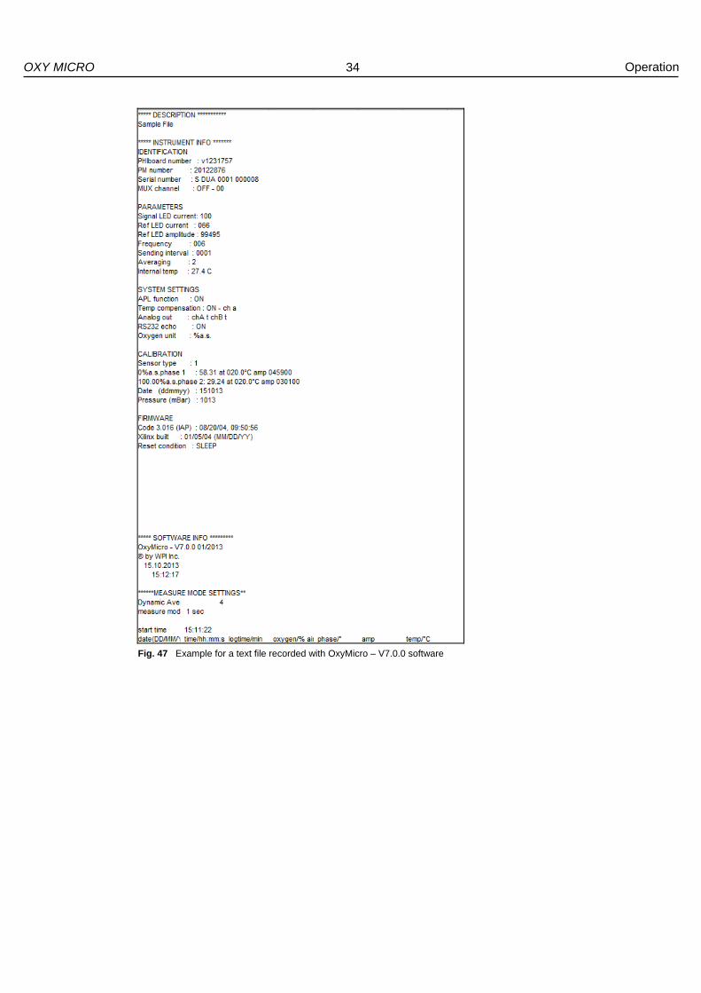
Your measurement data are displayed and can be processed now. In the head of the ASCII file (see Fig. 47), you find the Description of your measurement which you have entered when storing the file. Below, you find the Instrument Info containing the data of the complete calibration routine and some more important settings of the instrument and firmware. The Software Info below contains the version number of the software, date and time of the performed measurement. Below, you find the Measure Mode Settings containing the dynamic averaging, and the measuring mode.
The following rows, separated by semicolons, list the measuring data. The first two rows contain the date and time, the third the log-time in minutes, the fourth the oxygen content in the chosen unit. The raw data - phase angle in [°] and the amplitude in [r.U.] - are stored in the fifth and sixth row, respectively. The seventh row contains the temperature in °C measured by PT1000 temperature sensor.
The last row shows an Error Message for any error that might occur during measurement. E### is the byte error code:
Bit 0 ADC overflow
Bit 1 DC light overflow
Bit 2 Amplitude too low
Bit 3 No temperature sensor detected
Bit 4 Overheat
Bit 5 No oxygen calculation
Bit 6 Reserved
Bit 7 Reserved
Examples: E0 = No error E1 = Error : DC light overflow to much ambient light E12 = Error : no temp sensor & amplitude too low
Fig. 46 Text Import Wizard - Step 2
34
OXY MICRO Operation
Fig. 47 Example for a text file recorded with OxyMicro – V7.0.0 software

35
OXY MICRO Operation
4.7 Analog Output
Selecting the submenu Settings / Analog Output opens the dialog for selecting which data should be exported. There are two analog output channels available. You can choose one of the following parameters:
None
Oxygen
Phase
Amplitude
Temperature
! If you have adjusted the desired settings of the analog outputs and want to connect the
transmitter to a data logger, please close the software to store the settings before you disconnect the OXY MICRO from the computer.
For more detailed information about analog output specifications please refer to chapter 5.2 “Analog Output and External Trigger”.
Fig. 48 Analog Choice dialog

36
OXY MICRO Operation
4.8 LED Intensity
This function is for more experienced users to change the illumination level of the device. With a higher illumination level the signal-to-noise ratio can be improved, with a lower illumination level sensor bleaching can be avoided and its measurement stability prolonged. After changing LED-intensity the measurement parameters of the transmitter will change and the sensor has to be recalibrated. A warning message is displayed.
There are two options: In Auto Adjust mode the transmitter will adjust the illumination level automatically. Manual adjustment is possible in the Advanced mode.
Fig. 49 LED Adjust - Warning message
Fig. 50 LED Intensity Adjust – Auto Adjust tab
Fig. 51 LED Intensity Adjust – Advanced tab

37
OXY MICRO Operation
4.9 Software Menu Structure
Main Submenu 1 Submenu 2
File Exit closes the program.
Charts displays or hides the respective measurement graphs.
Oxygen Phase Amplitude Temperature
Display Zoom AutoScaleY automatically scales the y-axis. Undo Zoom restores the original display.
Clear Charts clears the graphs on the display Dimensions opens a dialog to choose the dimensions for the charts.
Print Charts prints the charts shown on the display.
Settings COM port allows choosing the serial COM port for the serial interface. Instrument Info opens the INFO tap in the graphical display. Analog Ouput opens a dialog to configure the analog out of the device. LED Intensity allows adjusting the illumination level of the sensor.

38
OXY MICRO Technical Data
5 Technical Data 5.1 Specifications
OPTICAL SENSOR
Oxygen sensor PSt1
Optical connector ST compatible, Core / Center 100 / 140
Channels 1
LED peak wavelength 505 nm
TEMPERATURE SENSOR
Potentiometric temperature sensor (Pt 1000)
Range 0 – 50 °C
Resolution ± 0.1 °C
Temperature sensor plug Plug type Lemo FGG.00.304.CLAD35
DC INPUT
DC-Supply: 18 V / 0.83 A / type TR15RA180
Use the provided parts only.
1 4
2 3

39
OXY MICRO Technical Data
DIGITAL INTERFACE
Serial communication a) RS232 serial interface
19200 Baud (Databits 8, Stoppbits 1, Parity none,
Handshake none)
b) USB interface
Transmitter port RJ11 4/4 socket
Serial interface cable to PC RJ11 4/4 to DSub9
USB interface cable to PC RJ11 4/4 to USB type A (transmitter adapted cable)
ENVIRONMENTAL CONDITIONS
Operating temperature 0 °C to 50 ºC
Storage temperature - 10 °C to 60 ºC
Relative humidity 0% to 80 % (non-condensing)

40
OXY MICRO Technical Data
OPERATION CONTROL
LED at the front panel
Red Device off Green Device on Orange Standby
DIMENSIONS / WEIGHT
185 mm x 110 mm x 45 mm
630 g

41
OXY MICRO Technical Data
5.2 Analog Output and External Trigger
The OXY MICRO is supplied with a dual programmable 12 bit analog output with galvanic isolation and an external trigger input.
ANALOG OUTPUT
Channels Dual voltage outputs
Output range 0 – 4095 mV
Socket type BNC connectors
Resolution 12 bit
Accuracy error ± 10 mV
Galvanic isolation 500 V rms
Shortcut protection Yes
Output parameters (PC software allows to
choose the parameter.)
O2
Temperature
Phase
Amplitude
0 – 4095 V Voltage Output:
Voltage 0 1000 (e. g.) 4095 V
Oxygen 0 100 409.5 % air sat.
Ampl. 0 20000 81900 r.U.
Phase 0 25 102.375 °
Temperatur 0 100 409.5 °C
Examples
Formula – Oxygen:
Formula – Amplitude:
Formula – Phase:
Formula – Temperature:
Oxygen [% air sat.] = Voltage [V] x 409.5 / 4.095
(e. g. 0.750 V = 75 % air sat.)
Ampl [r.U.] = Voltage [V] x 81.900 / 4.095
(e. g. 2.500 V = 50000 r.U.)
Phase [°] = Voltage [V] x 102.375 / 4.095
(e. g. 2.500 V = 62.50 °)
Temperature [°C] = Voltage [V] x 409.5 / 4.095
(e. g. 0.500 V = 50 °C)
Update rate Dependent on the sampling rate of the software. If an external trigger is used, the update rate is equivalent to the trigger pulse rate (min. 3 sec.).
42
OXY MICRO Technical Data
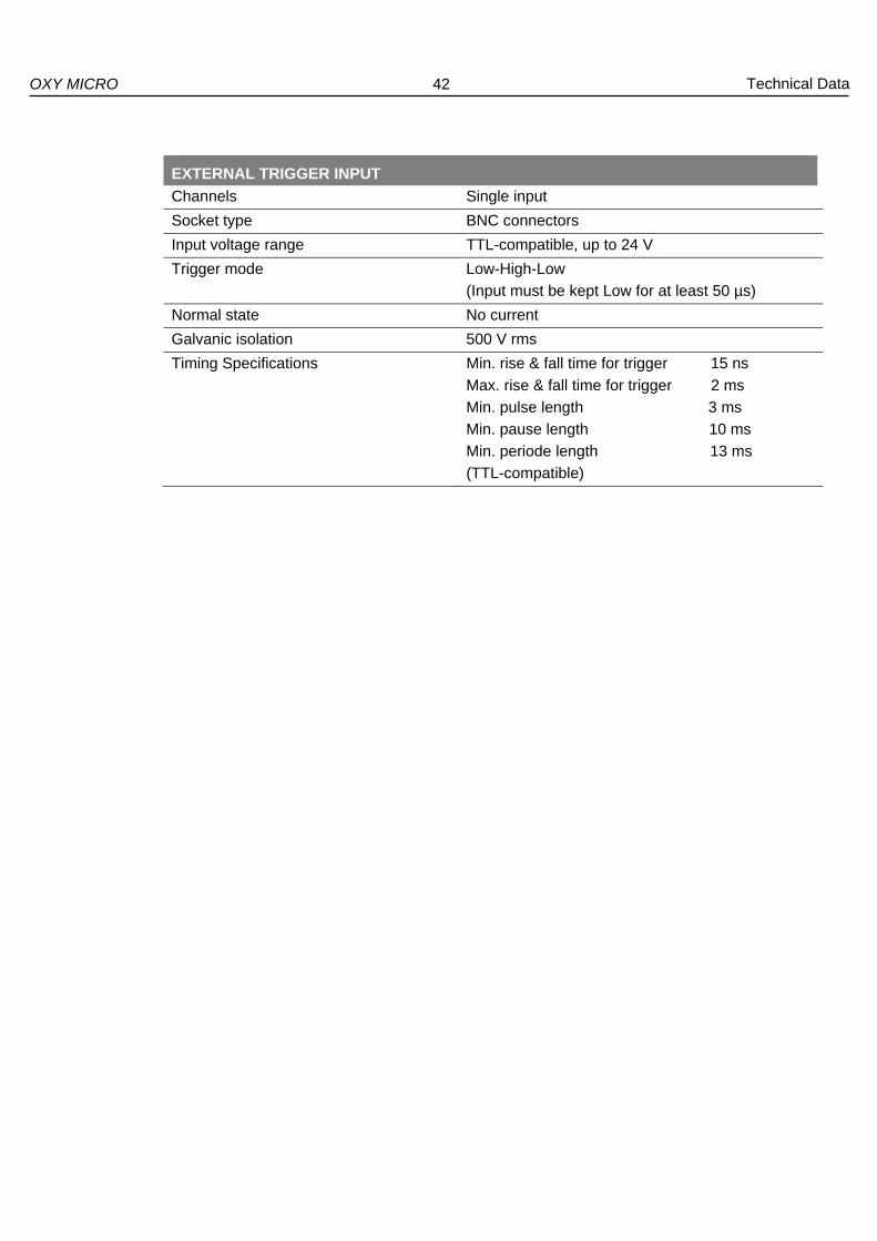
EXTERNAL TRIGGER INPUT
Channels Single input
Socket type BNC connectors
Input voltage range TTL-compatible, up to 24 V
Trigger mode Low-High-Low
(Input must be kept Low for at least 50 µs)
Normal state No current
Galvanic isolation 500 V rms
Timing Specifications Min. rise & fall time for trigger 15 ns
Max. rise & fall time for trigger 2 ms
Min. pulse length 3 ms
Min. pause length 10 ms
Min. periode length 13 ms
(TTL-compatible)
43
OXY MICRO Operational Notes
6 Operational Notes 6.1 Optical Output
The ST connector is a high precision optical component. Please keep it clean and dry. Always use the rubber cap to close the output when not in use.
6.2 Temperature Compensation
Use only the temperature sensor supplied. The use of any other temperature sensor may damage the device.
6.3 Warm-Up Time
The warm-up time of the electronic and opto-electronic components of the OXY MICRO is 5 minutes. After 5 min. stable measuring values will be obtained.
6.4 Power Adapter
OXY MICRO always has to be used with the original power adapter (100 - 240 VAC; 47 - 63 Hz; 18 V / 0.83 A; type TR15RA180) which is supplied. As an alternative power source a battery can be used that meets the DC input voltage given in chapter 5 “Technical Data”. The battery adapter cable is available as an additional accessory.
6.5 Analog Outputs
WARNING: The analog outputs are not protected against any input voltage. Any voltage applied to the analog outputs can cause irreversible damage to the transmitter.
6.6 RS232 Interface / USB Interface
The transmitter uses a special interface cable. A different cable can cause malfunction. Use the provided parts only.
6.7 Maintenance
The transmitter is maintenance-free. The housing should be cleaned with a cloth only. Avoid any moisture entering the housing. Never use benzine, acetone, alcohol or any other organic solvents. The ST fiber connector of the sensor can be cleaned only with lint-free cloth or a cleaning implement for ST connectors.

44
OXY MICRO Operational Notes
6.8 Service
Alignment, rework or repair work may only be carried out by a suitable qualified technician, trained by us. The safety of the user may be endangered, e. g., if the device
Is visibly damaged;
No longer operates as specified;
Has been stored under adverse conditions for a lengthy period of time;
Has been damaged in transport
If you are in doubt, the instrument should be sent back to the manufacturer for repair and maintenance. World Precision Instruments, Inc. Sarasota International Trade Center 175 Sarasota Center Boulevard Sarasota, FL 34240-9258 USA
Phone 941-371-1003 Fax 941-377-5428 E-mail: [email protected] www.wpiinc.com
Please contact our service team in case of any question. We look forward to helping you and are open for any proposition or criticism.

45
OXY MICRO CE and FCC Conformity
7 CE and FCC Conformity CE Conformity
The equipment is confirmed to comply with the requirements set out in the Council Directive relating to Electromagnetic Compatibility (2004/108/EEC) and for Low Voltage (2006/95/EEC). For the evaluation of above mentioned Council Directives following harmonized standards were consulted: EMC: EN 61326-1: 2006 LVD: EN 61010-1: 2010 Verification of FCC Rules
This equipment has been tested and found to comply with the limits for a Class B digital device, pursuant to part 15 of the FCC Rules. These limits are designed to provide reasonable protection against harmful interference in a residential installation. This equipment generates, uses, and can radiate radio frequency energy and, if not installed and used in accordance with the instructions, may cause harmful interference to radio communications. However, there is no guarantee that interference will not occur in a particular installation. If this equipment does cause harmful interference to radio or television reception, which can be determined by turning the equipment off and on, the user is encouraged to try to correct the interference by one or more of the following measures:
Reorient or relocate the receiving antenna.
Increase the separation between the equipment and receiver.
Connect the equipment into an outlet on a circuit different from that to which the
receiver is connected.
Consult the dealer or an experienced radio/TV technician for help.
46
OXY MICRO Concluding Remarks
8 Concluding Remarks Dear Customer, With this manual, we hope to provide you with an introduction to work with the OXY MICRO fiber optic oxygen transmitter. This manual does not claim to be complete. We are endeavored to improve and supplement this version. We are looking forward to your critical review and to any suggestions you may have. You can find the latest version at www.wpiinc.com. With best regards, Your WPI Team


World Precision Instruments, Inc. USA
International Trade Center, 175 Sarasota Center Blvd., Sarasota FL 34240-9258 Tel: 941-371-1003 - Fax: 941-377-5428 - E-mail: [email protected]
UK 1 Hunting Gate, Hitchin, Hertfordshire SG4 0TJ
Tel: 44 (0)1462 424700 - Fax: 44 (0)1462 424701 - E-mail: [email protected]
Germany Zossener Str. 55, 10961 Berlin
Tel: 030-6188845 - Fax: 030-6188670 - E-mail: [email protected] China & Hong Kong
WPI Shanghai Trading Co., Ltd. Rm 20a, No8 Dong Fang Rd., Lu Jia Zui Financial District, Shanghai PRC
Tel: +86 688 85517 - E-mail:[email protected]
Internet www.wpiinc.com - store.wpiinc.com
www.wpi-europe.com - www.wpiinc.cn
OXY MICRO Fiber Optic Oxygen Mesruement System
for Oxygen Microsensors
ro fiber optic pH