Embed Size (px)
Citation preview
Procedia Engineering 81 ( 2014 ) 2177 – 2183
Available online at www.sciencedirect.com
1877-7058 © 2014 The Authors. Published by Elsevier Ltd. This is an open access article under the CC BY-NC-ND license (http://creativecommons.org/licenses/by-nc-nd/3.0/).Selection and peer-review under responsibility of the Department of Materials Science and Engineering, Nagoya Universitydoi: 10.1016/j.proeng.2014.10.305
ScienceDirect
11th International Conference on Technology of Plasticity, ICTP 2014, 19-24 October 2014, Nagoya Congress Center, Nagoya, Japan
Twist springback of asymmetric thin-walled tube in mandrel rotary draw bending process
Xin Xue*, Juan Liao, Gabriela Vincze, Jose Gracio Centre for Mechanical Technology and Automation, Department of Mechanical Engineering, University of Aveiro, 3810-193, Aveiro, Portugal
Abstract
This paper aims to develop an effective numerical model and analyse the twist springback behaviour of asymmetric thin-walled tube in mandrel rotary draw bending. Yld2000-2d anisotropic yield criterion integrated with mixed isotropic and kinematic hardening model was used to describe the material properties including anisotropy and Bauschinger effect. The corresponding mechanical experiments such as uniaxial tension, monotonic and forward-reverse shear tests were performed to obtain the material parameters. A three-dimensional elastic-plastic finite element model was developed, and its validity was assessed by comparing the predicted twist springback with experiment one. Based on the present FE model, the tangential stress distribution during different bending steps were analysed to explore the source of twist springback. The results indicate that the torsion moment of cross sections caused by the non-homogenous stress states play a considerable role in twist springback prediction. © 2014 The Authors. Published by Elsevier Ltd. Selection and peer-review under responsibility of Nagoya University and Toyohashi University of Technology.
Keywords: Mandrel rotary draw bending; Twist springback; Asymmetric thin-walled tube; Bauschinger effect; Anisotropy
1. Introduction
Mandrel Rotary draw tube bending can be a complex non-linear physical process with coupling multi-factor interactive effects. As one of undesirable deformations caused by unbalanced elastic-plastic deformation and residual stress release after the dies are removed, twist springback inevitably occurs and leads to difficulty at the
* Corresponding author. Tel.: +351-923-232-366; fax: +351-234-370-953.
E-mail address: [email protected]
© 2014 The Authors. Published by Elsevier Ltd. This is an open access article under the CC BY-NC-ND license (http://creativecommons.org/licenses/by-nc-nd/3.0/).Selection and peer-review under responsibility of the Department of Materials Science and Engineering, Nagoya University
2178 Xin Xue et al. / Procedia Engineering 81 ( 2014 ) 2177 – 2183
assembly stage since the inaccurate geometry of product. In practice, the efficient control of the twist springback is still treated by the know-how experience and “try and error” experiments (Li et al., 2014). Meanwhile, the predicted result by analytical method deviates far from the experimental ones since the complicated multifactor forming conditions are difficult to be considered (Yang et al., 2010). Besides the experimental and analytical methods, the finite element method has become the primary tool for deep analysis of tube bending deformations. Recently, many efforts have been conducted to improve the springback prediction of the thin-walled bent tube. Zhao et al (2009) established a three-dimensional elastic-plastic finite element model of circular tube in rotary draw bending process. More detailed modelling conditions including the Bauschinger effect of material, the loading boundary conditions for the clamp die and the pressure die, the reasonable modification of the flexible mandrel constraint and the simplified half-tube model were considered by Zhu et al. (2012). Their results showed that the influence of material constitutive model on springback prediction is greater than that caused by simplifying finite element model or using different mass scaling factors. However, these researches have paid less attention on material anisotropy and tended to focus on tube profiles with symmetric cross sections such as circular, square and rectangular, rather than on asymmetric cross sections.
In this paper, a typical industrial frame, aluminium alloy thin-walled tube with asymmetric profile which has evident twist springback phenomenon in mandrel rotary draw bending can be addressed. The material anisotropy and Bauschinger effect which have a strong influence on springback simulation results should be accounted for by the constitutive description. The corresponding mechanical experiments including uniaxial tension and simple shear tests are performed to obtain the material parameters. A three-dimensional elastic-plastic finite element model is developed, and its validity is assessed by comparing the predicted twist springback with experiment one. To explore the source of twist springback, the tangential stress distributions during different bending steps are analysed and discussed.
Nomenclature
Bend angle Twist angle
Y Yield stress ratio in different direction r Plastic strain ratio
, 1 8 Coefficients of yld2000-2d 0 Initial yield stress along extrusion direction of the tube
Q, b c Coefficients of mixed isotropic and kinematic hardening model UR3 Rotation about 3-direction (z) of numerical element
2. Description of twist springback of thin-walled tube in mandrel rotary draw bending
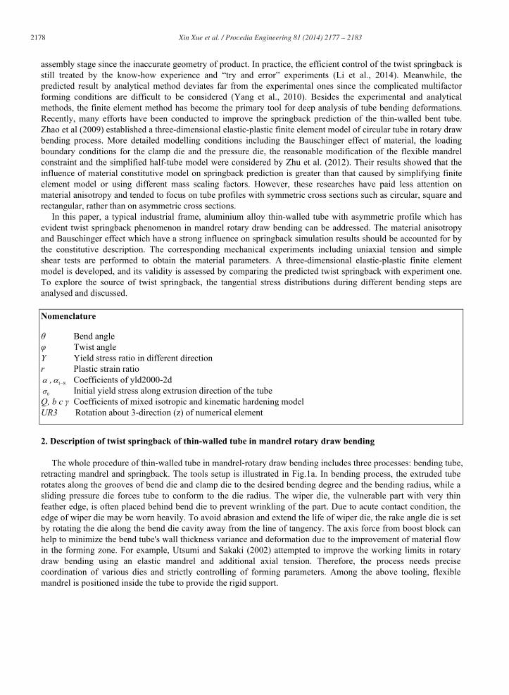
The whole procedure of thin-walled tube in mandrel-rotary draw bending includes three processes: bending tube, retracting mandrel and springback. The tools setup is illustrated in Fig.1a. In bending process, the extruded tube rotates along the grooves of bend die and clamp die to the desired bending degree and the bending radius, while a sliding pressure die forces tube to conform to the die radius. The wiper die, the vulnerable part with very thin feather edge, is often placed behind bend die to prevent wrinkling of the part. Due to acute contact condition, the edge of wiper die may be worn heavily. To avoid abrasion and extend the life of wiper die, the rake angle die is set by rotating the die along the bend die cavity away from the line of tangency. The axis force from boost block can help to minimize the bend tube's wall thickness variance and deformation due to the improvement of material flow in the forming zone. For example, Utsumi and Sakaki (2002) attempted to improve the working limits in rotary draw bending using an elastic mandrel and additional axial tension. Therefore, the process needs precise coordination of various dies and strictly controlling of forming parameters. Among the above tooling, flexible mandrel is positioned inside the tube to provide the rigid support.
2179 Xin Xue et al. / Procedia Engineering 81 ( 2014 ) 2177 – 2183
Fig. 1. (a) Illustration of tools setup for mandrel-rotary draw bending process (b) longitudinal springback angle (c) twist springback angle of cross sections.
In this paper, twist springback of the asymmetric thin-walled tube includes two main codes of deformation behaviours. In the longitudinal direction, the amount of springback is expressed as the value of springback angle
- ’ , (1)
where and ’ are the bending angles before and after springback, respectively, as shown in Fig.1b. In the circumferential direction (cross sections), the amount of twist can be decomposed into two parts: the
rotary angle of neutral axis of closed section and the warping angle of open section (fin). c and represent twist of the closed section and the open section, respectively, as shown in Fig.1c. It is known that twist deformation of open section should be much larger than that of closed rectangular section under the same process configurations. The reason is that the ratio of the angle of twist for the closed section to the open section is so small that the twist of closed rectangular part can be ignored. In this work, the twist springback angle can be given by
2( )= arctanf
UL
, (2)
where (U2) is the maximum displacement in the vertical direction (U2), and Lf is the length of fin (see Fig.1c).
3. Material and mechanical characterizations
In this work, Yld2000-2d anisotropic yield function (Barlat et al., 2003) and mixed isotropic and kinematic hardening model (Tang et al., 2010) are used to describe the behaviour of material anisotropy and capture the Bauschinger effect, respectively. Mechanical tests including uniaxial tension and forward-reverse shear are performed to accumulate sufficient data that can be used for the calibration and verification of constitutive models.
2180 Xin Xue et al. / Procedia Engineering 81 ( 2014 ) 2177 – 2183
Table 1. Anisotropic data of AA6060-T4 and material parameter constants for constitutive models.
Anisotropy Y0 Y45 Y90 Yb r0 r45 r90 rb 1 0.865 0.791 1 0.492 0.367 1.277 1
Yld2000-2d 1 2 3 4 5 6 7 8 0.426 1.806 0.875 1.051 1.034 0.952 0.924 1.487 8
Mixed hardening 0 (MPa) Q (MPa) b C (GPa)
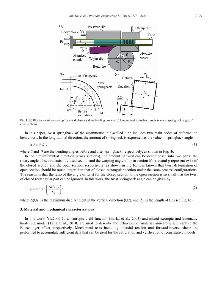
99.62 80.61 11.09 1397.64 15.80 The material used is aluminium alloy (AA6060-T4) with 2mm thickness, and its basic mechanical properties are
given as follows: Young’s modulus E = 51GPa; Possion’s ratio = 0.33. In order to obtain the material anisotropic parameters (see Table 1), uniaxial tension tests at the angles 0º, 45ºand 90º with respect to the extruding direction should be performed. Fig. 2a shows the stress-strain curves of tension tests at different directions. It has been shown that the anisotropic characteristic is evident and should be considered during the simulation.
Monotonic and forward-reverse shear tests at 7.5%, 15% and 23% pre-strain were performed, as shown in Fig.2b. Bauschinger effect is evident and may pay considerable effect on springback prediction. The material parameters for yld2000-2d anisotropic yield criterion and mixed isotropic and kinematic hardening model are listed in Table 1. These parameters will be introduced into finite element model to describe material hardening behaviors.
-0.30 -0.15 0.00 0.15 0.30
-150
-100
-50
0
50
100
150
Shea
r stre
ss (M
Pa)
Monotonic Isotropic Mixed Experiment
Shear strain
(b)
Fig.2. (a) Strain-stress curves of uniaxial tension tests under different loading directions with respect to extrusion direction (b) comparison of stress-strain relations between experiment and calculation results by forward-reverse sear tests.
4. Finite element modelling and its key techniques
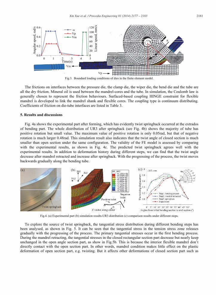
Experimental and simulative process conditions are the same, and the main process parameters are listed in Table 2. As two main section properties of element in the FE model, the rule and the point of thickness integration are Simpson and 15, respectively. Boundary loading conditions of the moveable dies are carried out through the linear velocity (Vp and Vm, mm/s) and angular velocity ( , rad/s), respectively, as shown in Fig.3.
Table 2. Main forming parameters of bending process. No. Parameters Values 1 Bending velocity, /(rad/s) 0.523 2 Bend angle, /(°) 45 3 Speed of Mandrel retracted, Vm (mm/s) 100 4 Minimum bend radius, R/(mm) 116 5 Speed of pressure die, Vp(mm/s) 50.5 6 Clearances between tube and tools (mm) 0.1 7 Booster, Pb (MPa) 0.3 8 Wiper die rake angle, /(°) 1 9 Mandrel flexible cores 5
Table 3. Coefficients of friction on die-tube interfaces. No. Contact interfaces Lubricant conditions CoFs1 Tube-bend die Dry 0.1 2 Tube- pressure die Dry 0.38 3 Tube- mandrel Mineral oil 0.08 4 Tube- wiper die Dry 0.15 5 Tube- clamp die Tough dry rough6 Mandrel shank- cores Mineral oil 0.1 Friction law: Coulomb; Constraint of flexible mandrel: Coupling HINGE ; Coupling type: Continuum distributing.
2181 Xin Xue et al. / Procedia Engineering 81 ( 2014 ) 2177 – 2183
0 1 2 3 4 50.0
0.2
0.4
0.6
Line
ar sp
eed,
mm
/s
Vp Vm
Time(s)
Ang
ular
spee
d, ra
d/s
020406080100120
Fig.3. Boundard loading conditions of dies in the finite element model.
The frictions on interfaces between the pressure die, the clamp die, the wiper die, the bend die and the tube are all the dry friction. Mineral oil is used between the mandrel-cores and the tube. In simulation, the Coulomb law is generally chosen to represent the friction behaviours. Surfaced-based coupling HINGE constraint for flexible mandrel is developed to link the mandrel shank and flexible cores. The coupling type is continuum distributing. Coefficients of friction on die-tube interfaces are listed in Table 3.
5. Results and discussions
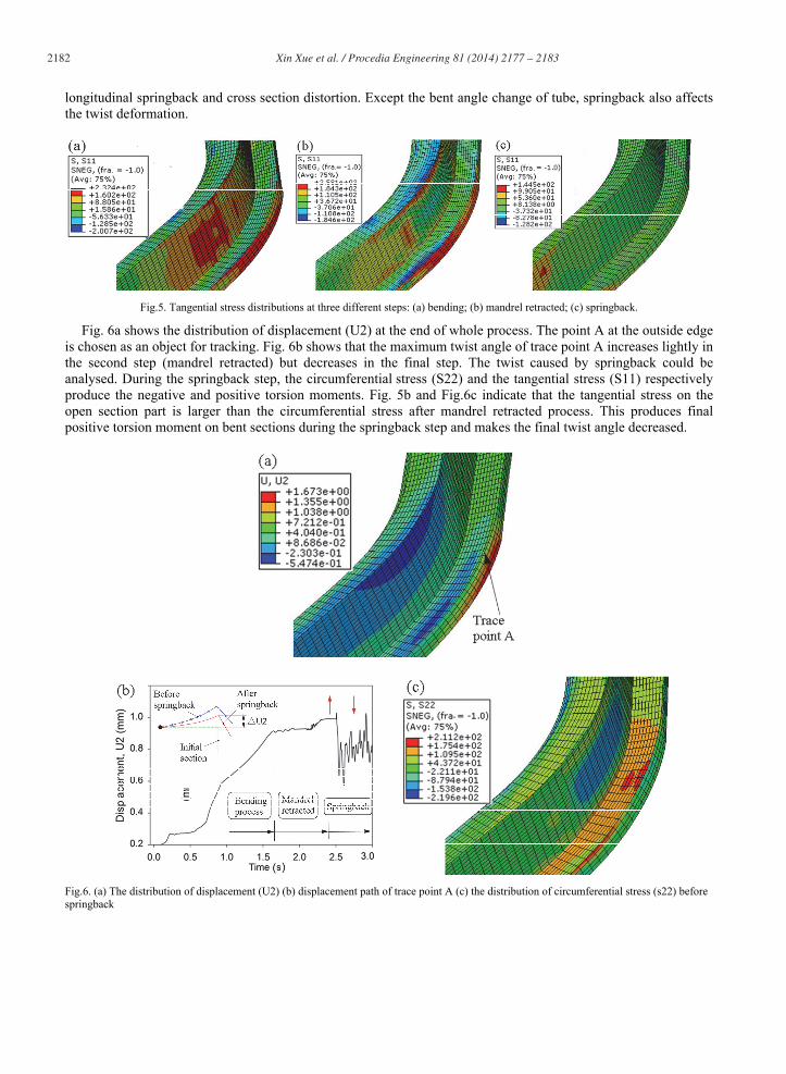
Fig. 4a shows the experimental part after forming, which has evidently twist springback occurred at the extrados of bending part. The whole distribution of UR3 after springback (see Fig. 4b) shows the majority of tube has positive rotation but small value. The maximum value of positive rotation is only 0.05rad, but that of negative rotation is much larger 0.48rad. This simulation result also indicates that the twist angle of closed section is much smaller than open section under the same configuration. The validity of the FE model is assessed by comparing with the experimental results, as shown in Fig. 4c. The predicted twist springback agrees well with the experimental results. In addition to deformation history during different steps, we can find that the twist angle decrease after mandrel retracted and increase after springback. With the progressing of the process, the twist moves backwards gradually along the bending tube.
Fig.4. (a) Experimental part (b) simulation results-UR3 distribution (c) comparison results under different steps.
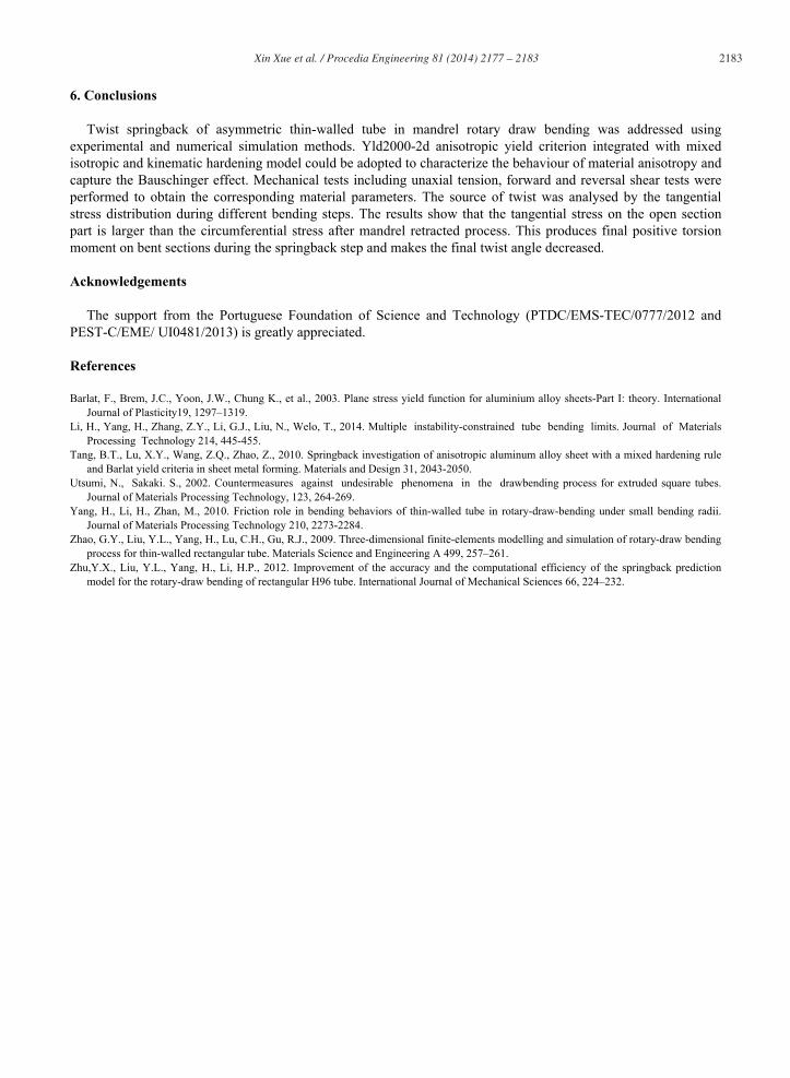
To explore the source of twist springback, the tangential stress distribution during different bending steps has
been analysed, as shown in Fig. 5. It can be seen that the tangential stress in the tension stress zone releases gradually with the progressing of the process. The primary tangential stresses occur in the first bending process. During the mandrel retracting, the tangential stresses in the closed rectangular section part decrease but nearly keep unchanged in the open angle section part, as show in Fig.5b. This is because the interior flexible mandrel don’t directly contact with the open section part. In other words, mandrel condition makes little effect on the plastic deformation of open section part, e.g. twisting. But it affects other deformations of closed section part such as
2182 Xin Xue et al. / Procedia Engineering 81 ( 2014 ) 2177 – 2183
longitudinal springback and cross section distortion. Except the bent angle change of tube, springback also affects the twist deformation.
Fig.5. Tangential stress distributions at three different steps: (a) bending; (b) mandrel retracted; (c) springback.
Fig. 6a shows the distribution of displacement (U2) at the end of whole process. The point A at the outside edge is chosen as an object for tracking. Fig. 6b shows that the maximum twist angle of trace point A increases lightly in the second step (mandrel retracted) but decreases in the final step. The twist caused by springback could be analysed. During the springback step, the circumferential stress (S22) and the tangential stress (S11) respectively produce the negative and positive torsion moments. Fig. 5b and Fig.6c indicate that the tangential stress on the open section part is larger than the circumferential stress after mandrel retracted process. This produces final positive torsion moment on bent sections during the springback step and makes the final twist angle decreased.
Fig.6. (a) The distribution of displacement (U2) (b) displacement path of trace point A (c) the distribution of circumferential stress (s22) before springback
2183 Xin Xue et al. / Procedia Engineering 81 ( 2014 ) 2177 – 2183
6. Conclusions
Twist springback of asymmetric thin-walled tube in mandrel rotary draw bending was addressed using experimental and numerical simulation methods. Yld2000-2d anisotropic yield criterion integrated with mixed isotropic and kinematic hardening model could be adopted to characterize the behaviour of material anisotropy and capture the Bauschinger effect. Mechanical tests including unaxial tension, forward and reversal shear tests were performed to obtain the corresponding material parameters. The source of twist was analysed by the tangential stress distribution during different bending steps. The results show that the tangential stress on the open section part is larger than the circumferential stress after mandrel retracted process. This produces final positive torsion moment on bent sections during the springback step and makes the final twist angle decreased.
Acknowledgements
The support from the Portuguese Foundation of Science and Technology (PTDC/EMS-TEC/0777/2012 and PEST-C/EME/ UI0481/2013) is greatly appreciated.
References
Barlat, F., Brem, J.C., Yoon, J.W., Chung K., et al., 2003. Plane stress yield function for aluminium alloy sheets-Part I: theory. International Journal of Plasticity19, 1297–1319.
Li, H., Yang, H., Zhang, Z.Y., Li, G.J., Liu, N., Welo, T., 2014. Multiple instability-constrained tube bending limits. Journal of Materials Processing Technology 214, 445-455.
Tang, B.T., Lu, X.Y., Wang, Z.Q., Zhao, Z., 2010. Springback investigation of anisotropic aluminum alloy sheet with a mixed hardening rule and Barlat yield criteria in sheet metal forming. Materials and Design 31, 2043-2050.
Utsumi, N., Sakaki. S., 2002. Countermeasures against undesirable phenomena in the drawbending process for extruded square tubes. Journal of Materials Processing Technology, 123, 264-269.
Yang, H., Li, H., Zhan, M., 2010. Friction role in bending behaviors of thin-walled tube in rotary-draw-bending under small bending radii. Journal of Materials Processing Technology 210, 2273-2284.
Zhao, G.Y., Liu, Y.L., Yang, H., Lu, C.H., Gu, R.J., 2009. Three-dimensional finite-elements modelling and simulation of rotary-draw bending process for thin-walled rectangular tube. Materials Science and Engineering A 499, 257–261.
Zhu,Y.X., Liu, Y.L., Yang, H., Li, H.P., 2012. Improvement of the accuracy and the computational efficiency of the springback prediction model for the rotary-draw bending of rectangular H96 tube. International Journal of Mechanical Sciences 66, 224–232.


![[3810-0170D]xpeedmini_outdoor_cnb_v10e_1 (1).pdf](https://img.pdfslide.us/doc/110x75/55cf8637550346484b9564db/3810-0170dxpeedminioutdoorcnbv10e1-1pdf.jpg)