Embed Size (px)
Citation preview
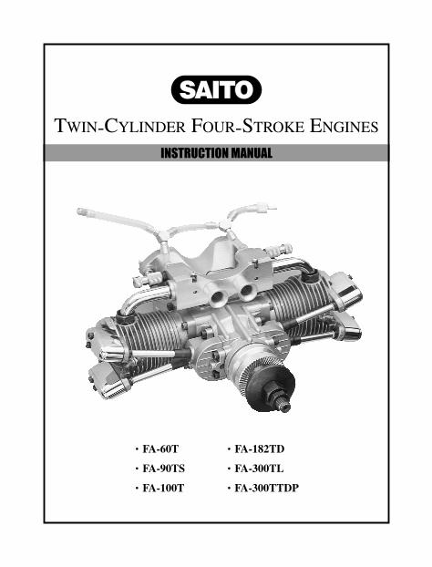
INSTRUCTION MANUAL
TWIN-CYLINDER FOUR-STROKE ENGINES
・FA-60T ・FA-182TD
・FA-90TS ・FA-300TL
・FA-100T ・FA-300TTDP

VERYIMPORTANT Failure to readand follow theseinstructions beforeyou proceed may result in enginedamage and thevoiding of yourwarranty.
S A F E T Y I N S T R U C T I O N S 1
IntroductionCongratulations on purchasing a Saito 4-cycle engine. Cared for properly, these high-quality. finely crafted engines offer many years of modelingenjoyment.
This instruction manual has been developed to ensure optimum performance from the Saito engine you have purchased. The instructions must be read through completely andunderstood thoroughly prior to mounting and running the engine.
Safety InstructionsThis model engine will give you considerable pleasure, satisfaction and performance if you strictly follow these safety instructions and take heed of the warnings as to its safe and proper use. Remember at all times, IT IS NOT A TOY, but a precision-built machine with more than enough power to cause harm if misused, or if the safety precautions are not observed.
You should always:
1. Mount the engine securely on thetest bench using the high-quality Saitomotor mount supplied. Never clampthe engine in a vice.
2. When running the engine, be sure that all spectators, especially children, are at least 20 feet away.
3. Use the correct size and pitch of propeller for your engine; refer to the propeller chart on page 18 of this manual.
4. It is extremely important to balance the propeller prior to installation. Failure to do so may cause damage to the Saito engine and/or the airframe. Install the propeller with the convex (curved) side facing forward. Securely tighten the propeller nut against the washer and propeller. A“jam”nut is suggested for all 4-cycle engines.
5. Inspect the tightness of the propeller nut prior to each flight.
6. Keep your face and body away from the path of the propeller blades when starting or running your engine.
7. Never allow your hands to come close to the propeller. Use either a“Start stick”or electric starter to start the engine.
8. Make all carburetor adjustmets from behind the propeller.
9. To stop the engine, cut off the fuel supply (pinch or disconnect the fuel line to the carburetor), or use the throttle linkage to shut off the air.
S A F E T Y I N S T R U C T I O N S2
DO NOT USE HANDS, FINGERS OR ANY OTHER PART OF THE BODY TO STOP THE PROPELLER. DO NOT THROW ANY OBJECT INTO A PROPELLER TO STOP IT.
10. Discard any propeller that is nicked, scratched, cracked or damaged in any way.
It is highly recommended that:
1. Safety glasses or goggles be worn when starting and running your engine.
2. You do not run the engine in the vicinity of loose gravel or sand. The propeller may throw such materials into your face and eyes. The engine may also ingest these harmful materials.
3. Loose clothing should be avoided when operating your model engine. Loose clothing may become entangled in the propeller, creating the possibility of bodily harm. Also, all loose objects (screwdrivers, pencils, nickel cadmium starters, etc.) should be removed from your pockets so they do not fall into the propeller.
4. Glow plug clips and cords are kept well away from the propeller.
5. Your glow fuel is kept in a safe place well away from sparks, heat or anything which can ignite the fuel.
Beware:
1. Model engines get very hot while running. Do not attempt ot handle them until they have cooled.
2. Always run your model engines in a well-ventilated area. Similar to automotive engines, model engines produce possibly barmful carbon monoxide fumes.
3. Remember that model engines produce a substantial amount of power, more than enough to seriously injure people and/or do considerable damage to property. Always use common sense, skill and constant observation of safety precautions.
DisassemblyDo not needlessly disassemble your Saito engine. Engine repairs should be performed only by qualified individuals. Damage due to improper disassembly will not be covered under the warranty.
S U P P O R T E Q U I P M E N T 3
Engine Parts IdentificationIt is important to be able to identify the parts of your Saito engines. In the back of this manual you will find an exploded view of Saito twin-cylinder engines, as well as a chart which includes part numbers and descriptions. This will assist you in easily and rapidly identifying the respective parts of your Saito engine.
Support EquipmentThe following items, which are not included with your Saito engine, are necessary in order to operate the model engine:
1. Fuel. For maximum protection and longevity of Saito engines, Saito recommends a fuel containing 20% oil and 10-15% nitro methane. If this blend is not readily available, the next best selection is a high quality 2-cycle glow fuel, such as Cool Power, K&B, Power Master, etc. Fuels composed entirely of castor oil are not recommended. Use of such fuels will void the warranty.
2. Propeller. Refer to the Propeller Selection Chart, located on page 18, to determine the best initial propeller for your particular application.
3. Glow Plug Battery. Your glow plug may be properly heated by several different sources. The Hangar 9 Power Panel (HAN106), when accompanied by a 12V sealed lead acid battery (HAN102) and a glow plug locking socket (HAN120), is an ideal source of heat for your glow plug.A conventional 1.5V heavy-duty dry cell battery with a glow plug locking socket (HAN120) or alligator clips can also be used. Additionally, there are several very good glow-starters (nickel cadmium powered glow plug ignitors) which work well. (HAN7101).
4. Glow Plug Wrench. A glow plug wrench is used to remove and tighten glow plugs. The Hangar 9 Long Reach Plug Wrench (HAN2510) is an excellent wrench to utilize as a longer shaft may be necessary to access the glow plug. This depends mostly upon engine installation.
5. Manual or Electric Starter. For manual starts, a“start stick”(HAN113) is highly recommended. never use your fingers to start any model engine, as doing so invites injury. There are a variety of electric starters on the market. The Hangar 9 PowerPro-HD 12V Starter (HAN102) will work perfectly on all of the twin-cylinder Saito engines.
S T A R T I N G T H E E N G I N E4
Break-InThe first run on any engine, wheter 2-cycle or 4-cycle, is critical to the future of the engine itself. During this time, metal mating parts (piston and cylinder, ball bearings, etc.) wear in. Care must be taken that the engine is clean and free of any dust or grit that may have accumulated while building the model.
There are two accepted methods for breaking in a new engine: test stand mounted and run or aircraft mounted and run. Either method is acceptable, however, mounting the engine to a test stand allows the engine to bo observed throughout its operation, as well as elevating it above the ground and away from harmful dust and dirt.
NOTE: Because your engine may have been sitting for an extended period of time prior to running it, a few drops of light oil applied through the crankcase breather nipple (19 on the exploded view), if applicable, and down the pushrod tubes (40) will ensure proper lubrication for the first run.
Regardless of the mounting method chosen for break-in, the following procedures are applicable:
1. Use a break-in fuel as described in the“Support Equipment”Section on page 3 of this manual.
2. Use the proper glow plugs. Your engine includes the Saito 400P (SAIP400S glow plug(s), which are also the standard replacement glow plugs for these engines You can also use Hanger 9’s Four Cycle Super Plug (HAN3011).
3. Select the correct propeller. To do so, refer to the Propeller Selection Chart on page 18 of this manual.
4. Make sure that the high speed needle valve(s)(85) are opened (turned counterclockwise) five full turns. This guarantees a very rich setting.
Do not adjust the low-speed needle valve(s) or airbleed screws (89) at this time. The low speed needle valve(s), or airbleed screws, are pre-adjusted at the factory for initial break-in.
5. The use of tachometer (HAN111) is highly recommended since the adjustment of a four-cycle engine: while similar to that of a 2-cycle engine, is more difficult to“set by ear,”therefore making it easier to damage the engine by“over leaning.”
S T A R T I N G T H E E N G I N E 5
Starting The Engine1. Make sure the glow plugs are installed and tightened.
2. Be sure the propeller is properly secured. The use of a“jam nut”is encouraged on 4-cycle engines.
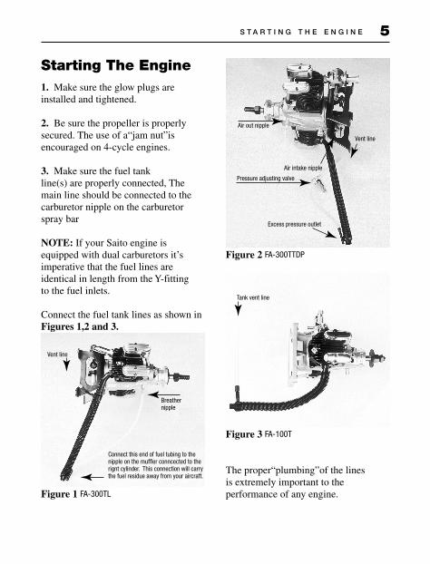
3. Make sure the fuel tank line(s) are properly connected, The main line should be connected to the carburetor nipple on the carburetor spray bar
NOTE: If your Saito engine is equipped with dual carburetors it’s imperative that the fuel lines are identical in length from the Y-fitting to the fuel inlets.
Connect the fuel tank lines as shown in Figures 1,2 and 3.
Figure 1 FA-300TL
Figure 2 FA-300TTDP
Figure 3 FA-100T
The proper“plumbing”of the lines is extremely important to the performance of any engine.
Vent line
Breathernipple
Connect this end of fuel tubing to thenipple on the muffler conncected to the rignt cylinder. This connection will carrythe fuel residue away from your aircraft.
Air out nipple
Air intake nipple
Pressure adjusting valve
Excess pressure outlet
Vent line
Tank vent line
S T A R T I N G T H E E N G I N E6
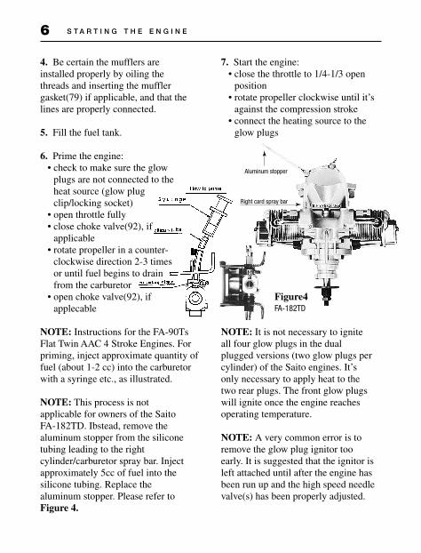
4. Be certain the mufflers are installed properly by oiling the threads and inserting the muffler gasket(79) if applicable, and that the lines are properly connected.
5. Fill the fuel tank.
6. Prime the engine:• check to make sure the glow
plugs are not connected to the heat source (glow plug clip/locking socket)
• open throttle fully• close choke valve(92), if
applicable• rotate propeller in a counter-
clockwise direction 2-3 times or until fuel begins to drain from the carburetor
• open choke valve(92), if applecable
NOTE: Instructions for the FA-90Ts Flat Twin AAC 4 Stroke Engines. For priming, inject approximate quantity of fuel (about 1-2 cc) into the carburetor with a syringe etc., as illustrated.
NOTE: This process is not applicable for owners of the Saito FA-182TD. Ibstead, remove the aluminum stopper from the silicone tubing leading to the right cylinder/carburetor spray bar. Inject approximately 5cc of fuel into the silicone tubing. Replace the aluminum stopper. Please refer to Figure 4.
7. Start the engine:• close the throttle to 1/4-1/3 open
position• rotate propeller clockwise until it’s
against the compression stroke• connect the heating source to the
glow plugs
Figure4FA-182TD
NOTE: It is not necessary to ignite all four glow plugs in the dual plugged versions (two glow plugs per cylinder) of the Saito engines. It’s only necessary to apply heat to the two rear plugs. The front glow plugs will ignite once the engine reaches operating temperature.
NOTE: A very common error is to remove the glow plug ignitor too early. It is suggested that the ignitor is left attached until after the engine has been run up and the high speed needle valve(s) has been properly adjusted.
Aluminum stopper
Right card spray bar
S T A R T I N G T H E E N G I N E 7
• Using either the“Start stick”or electric starter, spin the propeller until the engine is running.
NOTE: When using an electric starter, care should be taken to be sure that the engine does not become“hybro-locked.”While the electric starter will turn the engine over, it may damage the connecting rod or other components. If the engine becomes hydro-locked, simply remove the glow plugs and turn the engine over a few times with the“Start stick”or electric starter. The excess fuel will be forced to exit the engine via the cylinder heads.
8. Initial break-in:Do not exceed 4,000 rpm for the first ten(10) minutes of operation. This allows all parts to mate properly with good lubrication.
NOTE: Due to the excessively“rich”mixture setting, it may be necessary to leave the heat source attached to the glow plugs.
Subsequent runs may be made while slightly leaning out the mixture with each tank full of fuel. Generally, 40 minutes is considered sufficient for normal break-in prior to the first flight.
9. After break-in:
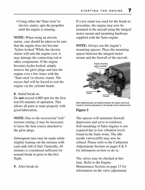
If a test stand was used for the break-in procedure, the engine may now be mounted in the aircraft using the integral motor mount and mounting hardware supplied with the Saito engine.
NOTE: Always use the engine’s mounting spacers. Place the mounting spacer between the integral motor mount and the firewall of the aircraft.
Figure 5
The spacers will minimize firewall depression and serve to reinforce. Soft mounting of Saito engines is not required due to low vibration levels found in the Saito twins. The idle needle valve(s)(89) may now be refined. Please refer to the Carburetor Adjustments Section on pages 8 & 9 for infrmation on bow to do so.
The valves may be checked at this time. Refer to the Engine Maintenance Section on page 13 for information on the valve adjustment.
Engine mountingspacer (washer)
EngineFirewall
Engine mountingspacer (washer)
EngineFirewall
When tightening bolts, put washers between the engine mount andfirewall to minimize depression on the firewall and for reinforcement.

E N G I N E O P E R A T I O N 8
The use of a tachometer is encouraged for setting the high-speed needle valve(s)(85) prior to flight. The peak rpm should be obtained and then reduced by approximately 200-300 rpm by turning the high speed needle valve(s) counterclockwise.
Low Speed Carburetor AdjustmentsThe low speed, or idle needle valve(s), or airbleed screws(s)(89), is/are pre-adjusted at the factory for best performance during break-in. After break-in it may be necessary to“fine tune”the low speed adjustment using the following procedure.
1. Start the engine and let it warm up prior to attempting any adjustments.
2. Close the throttle slowly and adjust the low speed setting by rotating the needle valve(s)(89) clockwise to lean te mixture and counterclockwise to richen the mixture. The direction of rotation is reversed for the Saito FA-100T and FA-182TD. These engines are equipped with airbleed style carburetors, rotating the airbleed screw clockwise will richen the mixture. If the airbleed screw is rotated counterclockwise the mixture will become lean.
NOTE: The fuel mixture is too rich if when you open the throttle rapidly the engine emits white smoke and“stutters”or“stumbles.”Correct this by rotating the idle needle valve(s) clockwise (or airbleed screws counterclockwise) 1/4 to 1/2 turn at a time until the engine transitions smoothly without hesitation upon opening the throttle rapidly. The fuel mixture may be too lean when the engine stops at the lowest idle position, or if the engine stops when the throttle is rapidly opened from idle. Attempt to correct this by rotating the idle needle valve(s) counterclockwise (or airbleed screws clockwise) 1/4 to 1/2 turn at a time until the engine transitions smoothly without hesitation upon opening the throttle rapidly. If the situation is not rectified by counterclockwise rotations of the idle needle valve(s) (or airbleed screws clockwise), try turning the idle needle valve clockwise (re airbleed screws counterclockwise) in 1/4 to 1/2 turn increments.
3. After obtaining the proper idle setting, the low rpm setting can be made through the positioning of the throttle adjustment screw if applicable. If not, adjust the idle setting via the throttle trim of your transmitter.
E N G I N E O P E R A T I O N 9
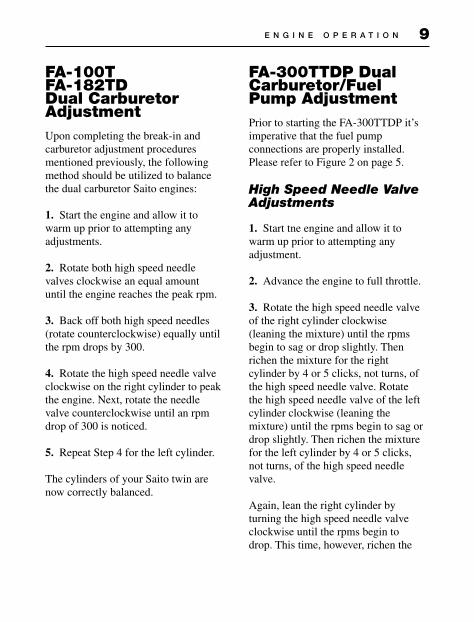
FA-100TFA-182TDDual CarburetorAdjustmentUpon completing the break-in and carburetor adjustment procedures mentioned previously, the following method should be utilized to balance the dual carburetor Saito engines:
1. Start the engine and allow it to warm up prior to attempting any adjustments.
2. Rotate both high speed needle valves clockwise an equal amount until the engine reaches the peak rpm.
3. Back off both high speed needles (rotate counterclockwise) equally until the rpm drops by 300.
4. Rotate the high speed needle valve clockwise on the right cylinder to peak the engine. Next, rotate the needle valve counterclockwise until an rpm drop of 300 is noticed.
5. Repeat Step 4 for the left cylinder.
The cylinders of your Saito twin are now correctly balanced.
FA-300TTDP DualCarburetor/FuelPump AdjustmentPrior to starting the FA-300TTDP it’s imperative that the fuel pump connections are properly installed. Please refer to Figure 2 on page 5.
High Speed Needle Valve Adjustments
1. Start tne engine and allow it to warm up prior to attempting any adjustment.
2. Advance the engine to full throttle.
3. Rotate the high speed needle valve of the right cylinder clockwise (leaning the mixture) until the rpms begin to sag or drop slightly. Then richen the mixture for the right cylinder by 4 or 5 clicks, not turns, of the high speed needle valve. Rotate the high speed needle valve of the left cylinder clockwise (leaning the mixture) until the rpms begin to sag or drop slightly. Then richen the mixture for the left cylinder by 4 or 5 clicks, not turns, of the high speed needle valve.
Again, lean the right cylinder by turning the high speed needle valve clockwise until the rpms begin to drop. This time, however, richen the
E N G I N E O P E R A T I O N 10
Air out nipple
Air intake nipple
Pressure adjusting valve
Excess pressure outlet
Vent line
fuel mixture by rotating the high speed needle valve counterclockwise 3 clicks. Lean the left cylinder by turning the high speed needle valve clockwise until the rpms begin to drop. This time, however, richen the fuel mixture by rotating the high speed needle valve counterclockwise 3 clicks. The high speed needle valve adjustments are now completed.
Idle Needle Valve Adjustment
1. Lower the throttle of the Saito FA-300TTDP to the lowest possible idle while retaining its reliability. Make sure the carburetor linkage assembly is secured to prevent movement of the throttle levers.
2. Lean the right cylinder low speed mixture screw (turning the screw clockwise) until the rpms dorp off slightly. Richen the low speed mixture by turning the idle screw 1/8 to 1/4 turn counterclockwise. Lean the left cylinder low speed mixture screw (turning the screw clockwise) until the rpms drop off slightly. Richen the low speed mixture by turning the idle screw 1/8 to 1/4 turn counterclockwise.
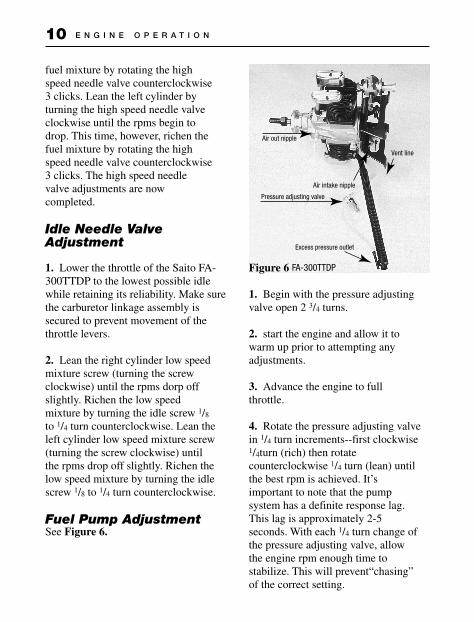
Fuel Pump AdjustmentSee Figure 6.
Figure 6 FA-300TTDP
1. Begin with the pressure adjusting valve open 2 3/4 turns.
2. start the engine and allow it to warm up prior to attempting any adjustments.
3. Advance the engine to full throttle.
4. Rotate the pressure adjusting valve in 1/4 turn increments--first clockwise 1/4turn (rich) then rotate counterclockwise 1/4 turn (lean) until the best rpm is achieved. It’s important to note that the pump system has a definite response lag. This lag is approximately 2-5 seconds. With each 1/4 turn change of the pressure adjusting valve, allow the engine rpm enough time to stabilize. This will prevent“chasing”of the correct setting.
E N G I N E O P E R A T I O N 11
Normal EngineOperationIf break in was accomplished on a test bench your engine may be mounted to the aircraft and flown. The initial flight should be performed with the engine adjusted for a rich fuel mixture.
1. Your Saito engine should be securely mounted to the aircraft using the motor mount and hardware kit provided. Soft mounting of the Saito twins is not necessary due to the extremely low vibration level of these engines. Please refer to Step 9 in the Starting The Engine section for the proper mounting procedure.
2. General operating procedures which ensure long engine life are:
Do not operate the engine with a“lean”mixture setting.
When installing the mufflers, oil both the manifold threads and the engine cylinder threads. Secure the mufflers to the airframe using the muffler brackets supplied.
NOTE: The muffler brackets are not supplied with the FA-182TD.
Regularly check all screws and nuts on both the engine and muffler.
After 1-2 hours of operation, valve adjustment may be necessary. Adjust the valves as shown in the Engine Maintenance Section following.
For engines equipped with a breather nipple, it’s recommended that a length of silicone fuel tubing be attached to this crankcase breather nipple(19). This is used to route away expelled oil from the engine compartment.
Engine MaintenanceDO NOT DISMANTLE THE ENGINE UNLESS ABSOLUTELY NECESSARY.
If it becomes necessary to dismantle your Saito engine, the following procedure should be followed:
It’s important to maintain identification of the“left”and“right”cylinder parts when dismantling and reassembling the engine. Looking forward from the rear of the engine with the engine upright, the cylinder on the right side is indeed the right cylinder. Therefore, the cylinder to the left is, of course, the left cylinder.
1. Cylinder and cam housing screws should be loosened in a criss-cross pattern.
E N G I N E M A I N T E N A N C E 12
Crankshaftalignmentmark
Crankcasemark
Crankshaftalignmentmark
Crankcasemark
Crankcase alignmentmark
Camgearreferencemark
Crankcase alignmentmark
Camgearreferencemark
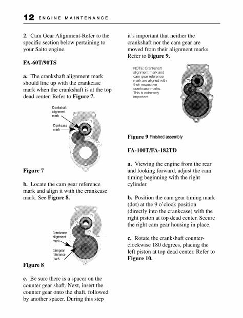
2. Cam Gear Alignment-Refer to the specific section below pertaining to your Saito engine.
FA-60T/90TS
a. The crankshaft alignment mark should line up with the crankcase mark when the crankshaft is at the top dead center. Refer to Figure 7.
Figure 7
b. Locate the cam gear reference mark and align it with the crankcase mark. See Figure 8.
Figure 8
c. Be sure there is a spacer on the counter gear shaft. Next, insert the counter gear onto the shaft, followed by another spacer. During this step
it’s important that neither the crankshaft nor the cam gear are moved from their alignment marks. Refer to Figure 9.
Figure 9 Finished assembly
FA-100T/FA-182TD
a. Viewing the engine from the rear and looking forward, adjust the cam timing beginning with the right cylinder.
b. Position the cam gear timing mark (dot) at the 9 o’clock position (directly into the crankcase) with the right piston at top dead center. Secure the right cam gear housing in place.
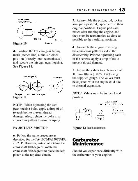
c. Rotate the crankshaft counter-clockwise 180 degrees, placing the left piston at top dead center. Refer to Figure 10.
NOTE: Crankshaftalignment mark andcam gear referencemark are aligned withtheir respectivecrankcase marks. This is extremelyimportant.
E N G I N E M A I N T E N A N C E 13
Figure 10
d. Position the left cam gear timing mark (etched line) at the 3 o’clock position (directly into the crankcase) and secure the left cam gear housing. See Figure 11.
Figure 11
NOTE: When tightening the cam gear housing bolts, apply a drop of oil to each bolt to prevent thread damage. Also, tighten the bolts in a criss-cross pattern to avoid warping.
FA-300TL/FA-300TTDP
e. Follow the same procedure as described for the FA-100T/FA130TD/FA-182TD. However, instead of rotating thecrankshaft 180 degrees, rotate the crankshaft 360 degrees to place the left piston at the top dead center.
3. Reassemble the piston, rod, rocker arm, pins, pushrod, tappet, etc. in their original positions. Engine parts are mated after running the engine, and they must be reassembled as close as possible to their original position.
4. Assemble the engine reversing the criss-cross pattern used in the disassembly. Prior to tightening each of the screws, apply a drop of oil to prevent thread damage.
5. Adjust the valves to a clearance of .03mm-.10mm (.002''-.004'') using the supplied gauge. The valves must be adjusted with the engine cold due to thermal expansion.
NOTE: Valves must be in the closed position.
Figure 12 Tappet adjustment
CarburetorMaintenanceShould you experience difficulty with the carburetor of your engine:
CARBURETOR MAINTENANCE14
1. Remove the high speed needle(s)(85) and flush out the spray bar with clean fuel. Replace the high speed needle(s) and follow the instructions in the carburetor adjustment section.
2. Always use a high-quality 4-cycle glow plug. The Hangar 9/McCoy MC-4C is highly recommended.
Tips For Extended Engine LifeTo add longer life to your Saito engine, we recommend the following:
1. Use a fuel containing 20% lubricants.
2. Use the recommended glow plugs.
3. Use the proper propeller size and balance the propeller prior to use.
4. Use a tachometer for precise engine adjustments.
5. Use an“after-run”oil when you’re finished flying for the day.
6. For long-term storage, make sure there is no fuel left in the tank and the engine. Remove the glow plug and apply several drops of high-quality oil (i.e., Marvel Air Tool Oil) to the top of the engine, down the pushrod tubes, and through the crankcase pressure vent if applicable. Rotate the crankshaft several times. Store the engine in the box or on the airplane with the nose down in order to keep oil in the bearings.
TroubleshootingGenerally speaking, there are very few things that will keep today’s modern glow engines from starting. To that end, make sure you’re using good quality“fresh”fuel, there are good glow plugs installed, and the starting battery is charged and in good condition. Should the engine fail to start after these items are verified, refer to the chart on the following page.
T R O U B L E S H O O T I N G 15
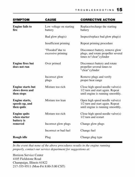
SYMPTOM
Engine fails to fire
Engine fires but does not run
Engine starts but slows down and then stops
Engine starts, speeds up, and then quits
Engine quits when starter battery is removed
Rough idle
CAUSE
Low voltage on starting battery
Bad glow plug(s)
Insufficient priming
“Flooded”due to excessive priming
Over primed
Incorrect glow plugs
Mixture too rich
Mixture too lean
Mixture too rich
Incorrect glow plugs
Incorrect or bad fuel
Plug
CORRECTIVE ACTION
Replace/recharge the starting battery
Inspect/replace bad glow plug(s)
Repeat priming procedure
Disconnect battery, remove glow plugs, and rotate propeller several times to“clear”cylinder
Disconnect battery and rotate propeller several times to“clear”cylinder
Remove plugs and verify proper heat range
Close high speed needle valve(s) 1/2 turn and start again. Repeat until engine is running smoothly.
Open high speed needle valve(s) 1/2 turn and start again. Repeat until engine is running smoothly.
Close high speed needle valve(s) 1/2 turn and restart
Change glow plugs
Change fuel
Change plug type
In the event that none of the above procedures results in the engine running properly, contact our service department for suggestions at:
Horizon Service Center4105 Fieldstone RoadChampaign, Illinois 61822217-355-9511 (Mon-Fri 8:00-5:00 CST)
T R O U B L E S H O O T I N G16
ITEM
01 Cylinder, Left02 Cylinder, Right06 Piston07 Piston Pin08 Piston Pin Ret09 Piston Ring10 Con Rod11 Linked Con Rod12 Conrod Linkpin/Scr13 Con Rod Screw14 Cyl Screw Set15 Crankcase17 Rear Cover(A)18 Rear Cover(B)19 Breather Nipple20 Frt Ball Bearing21 Main Ball Bearing22 Rear Ball Bearing23 Crankshaft24 Pinion-crankshaft25 Pinion gear pin26 Collar, Crankshaft27 Tapered Collet & Drv28 Prop Wash/Nut29 Prop Nut Spinner30 Prop Nut Elect31 Crankcase Screw S32 Eng Gasket Set33 Cam Gear Housing34 Cam Gear Left35 Cam Gear Right36 Cam Gear Shaft37 Tef/Steel Wash Set38 Tappet39 Pushrod40 Push Rd Cvr Rb sea41 Rocker Arm42 Rckr arm scrw nut43 Rckr arm pin44 Rckr arm brak left45 Rckr arm brak right46 Valve in/out47 Vlv spg/kpr/rtr48 Vlv Retainer49 Rocker Arm Cover52 Counter Gear53 Counter Gear Shft64 Air pump Assy65 Air pump housing66 Dlap/chk vlv rbr set67 Dlap/push rd/retn sp68 Check valve in/out69 Intake manifold, rt70 Intake manifold, lft71 Intake manifold nut
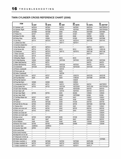
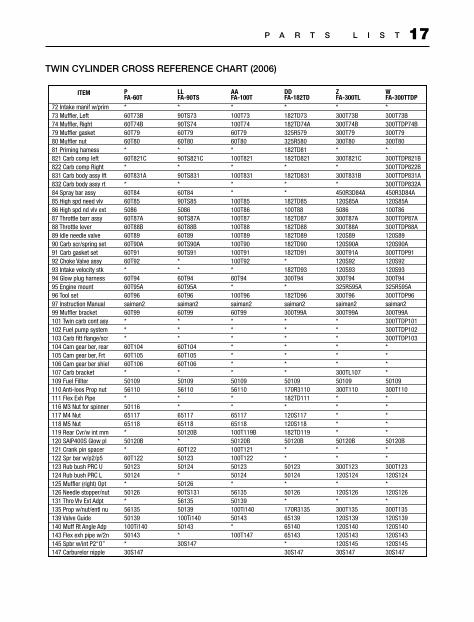
TWIN CYLINDER CROSS REFERENCE CHART (2006)
PFA-60T60T01A60T02A60T06A60T07500860T0960T10**60T1360T1460T1560T1760T1865195020A60T2160T2260T23A***60T275628*5030A60T3160T32**60T35*60T37503860T3960T4060T4160T4260T43**60T485047504860T49325R55260T53*****60T6960T7060T71
LLFA-90TS90TS0190TS0290TS064507A500845S0990TS10**90TS1360T1490TS1590TS1790TS1865195020A60T2160T2290TS23A***60T275628*5030A60T3160T32**60T35*60T37503890TS3990TS4060T4160T4260T43**90TS465047504860T49325R55260T53*****90TS6990TS70100T71
AAFA-100T100T01100T025006500750085009100T10100T11**5014100T15**5019100T20A*100T22A100T23A100T245025100T2665275628*5030A100T31100T32A5033A130T3450355036A5037503850395040504150425043**5046504750485049A*******100T69100T70100T71
DDFA-182TD182TD01182TD0291S0691S07650891S09182TD10182TD11**6514182TD15**6519182TD20*182TD22182TD23A***120S27A170R328120S29120S30182TD31182TD32A182TD33A182TD346535A182TD36A5037503891S3960T40504160T425043**91S46654750485049A*******182TD69182TD70182TD71
ZFA-300TL300T01A300T02A300T06A120S07300T08300T09A300T10C**300T13120S14A300T15B300T17*6619300T20A300T21300T22300T23D***300T27B300T28B**300T31300TL32A300T33300T34120S355036A120S37120S38300T39300T40A120S41300T42120S43120S44120S45120S46300T47120S48120S49*******300TL69A300TL70B300TL71
WFA-300TTDP300TTDP01A300TTDP02A300T06A120S07300T08300T09A300T10C**300T13120S14A300T15B300T17**300T20A300T21300T22300T23D***300T27B300T28B**300TTDP31300TTDP32A300T33300T34120S355036A120S37120S38300T39300T40A120S41300T42120S43120S44120S45120S46300T47120S48120S49******130T68A***
P A R T S L I S T 17
ITEM
72 Intake manif w/prim73 Muffler, Left74 Muffler, Right79 Muffler gasket80 Muffler nut81 Priming hamess821 Carb comp left822 Carb comp Right831 Carb body assy lft832 Carb body assy rt84 Spray bar assy85 High spd need vlv86 High spd nd vlv ext87 Throttle barr assy88 Throttle lever89 ldle needle valve90 Carb scr/spring set91 Carb gasket set92 Choke Valve assy93 Intake velocity stk94 Glow plug harness95 Engine mount96 Tool set97 Instruction Manual99 Muffler bracket101 Twin carb cont asy102 Fuel pump system103 Carb fitt flange/scr104 Cam gear ber, rear105 Cam gear ber, Frt106 Cam gear ber shiel107 Carb bracket109 Fuel Fillter110 Anti-loos Prop nut111 Flex Exh Pipe116 M3 Nut for spinner117 M4 Nut118 M5 Nut119 Rear Cvr/w int mm120 SAIP400S Glow pl121 Crank pin spacer122 Spr bar w/p2/p5123 Rub bush PRC U124 Rub bush PRC L125 Muffler (right) Opt126 Needle stopper/nut131 Thro Vlv Ext Adpt135 Prop w/nut/entl nu139 Valve Guide140 Muff Rt Angle Adp143 Flex exh pipe w/2n145 Spbr w/int P2“O”147 Carburelor nipple
PFA-60T*60T73B60T74B60T7960T80*60T821C*60T831A*60T8460T85508660T87A60T88B60T8960T90A60T9160T92*60T9460T95A60T96saiman260T99***60T10460T10560T106*5010956110*501166511765118*50120B*60T1225012350124*50126*5613550139100Ti14050143*30S147
LLFA-90TS*90TS7390TS7460T7960T80*90TS821C*90TS831*60T8490TS85508690TS87A60T88B60T8990TS90A90TS91**60T9460T95A60T96saiman260T99***60T10460T10560T106*5010956110**651176511850120B*60T1225012350124*5012690TS1315613550139100Ti14050143*30S147
AAFA-100T*100T73100T7460T7960T80*100T821*100T831**100T85100T86100T87100T88100T89100T90100T91100T92*60T94*100T96saiman260T99*******5010956110**6511765118100T119B50120B100T121100T1225012350124*5613550139100Ti14050143*100T147
DDFA-182TD*182TD73182TD74A325R579325R580182TD81182TD821*182TD831**182TD85100T88182TD87182TD88182TD89182TD90182TD91*182TD93300T94*182TD96saiman2300T99A*******50109170R3110182TD111*120S117120S118182TD11950120B**5012350124*50126*170R3135651396514065143*30S147
ZFA-300TL*300T73B300T74B300T79300T80*300T821C*300T831B*450R3D84A120S85A5086300T87A300T88A120S89120S90A300T91A120S92120S93300T94325R595A300T96saiman2300T99A******300TL10750109300T110*****50120B**300T123120S124*120S126*300T135120S139120S140120S143120S14530S147
WFA-300TTDP*300T73B300TTDP74B300T79300T80*300TTDP821B300TTDP822B300TTDP831A300TTDP832A450R3D84A120S85A100T86300TTDP87A300TTDP88A120S89120S90A300TTDP91120S92120S93300T94325R595A300TTDP96saiman2300T99A300TTDP101300TTDP102300TTDP103****50109300T110*****50120B**300T123120S124*120S126*300T135120S139120S140120S143120S14530S147
TWIN CYLINDER CROSS REFERENCE CHART (2006)
P A R T S L I S T18
You will note a letter (A, B, C. etc.) stamped on the top of the motor mount. This letter identifies the
production version of your engine. Should you ever need to order a part or have a question pertaining to
your engine, specify this letter along with the engine type. This will allow ease in identifying your engine.
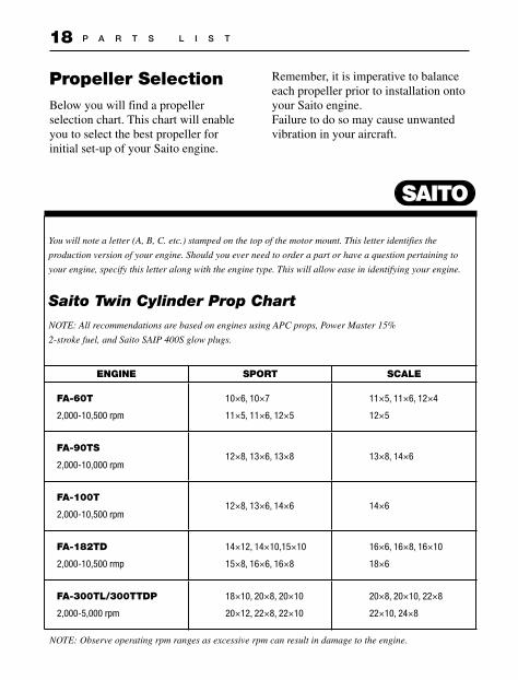
Saito Twin Cylinder Prop ChartNOTE: All recommendations are based on engines using APC props, Power Master 15%
2-stroke fuel, and Saito SAIP 400S glow plugs.
ENGINE SPORT SCALE
FA-60T
2,000-10,500 rpm
10×6, 10×7
11×5, 11×6, 12×5
11×5, 11×6, 12×4
12×5
FA-90TS
2,000-10,000 rpm12×8, 13×6, 13×8 13×8, 14×6
FA-100T
2,000-10,500 rpm12×8, 13×6, 14×6 14×6
FA-182TD
2,000-10,500 rmp
14×12, 14×10,15×10
15×8, 16×6, 16×8
16×6, 16×8, 16×10
18×6
FA-300TL/300TTDP
2,000-5,000 rpm
18×10, 20×8, 20×10
20×12, 22×8, 22×10
20×8, 20×10, 22×8
22×10, 24×8
Propeller SelectionBelow you will find a propeller selection chart. This chart will enable you to select the best propeller for initial set-up of your Saito engine.
Remember, it is imperative to balance each propeller prior to installation onto your Saito engine. Failure to do so may cause unwanted vibration in your aircraft.
NOTE: Observe operating rpm ranges as excessive rpm can result in damage to the engine.
P R O P E L L E R S E L E C T I O N 19
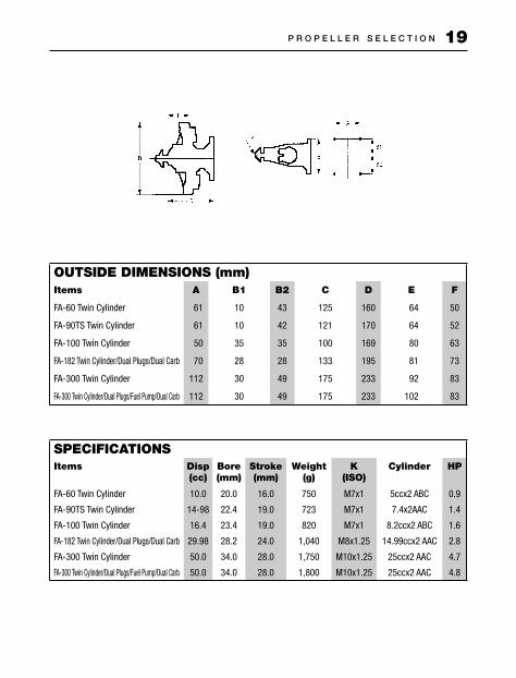
OUTSIDE DIMENSIONS (mm)Items A B1 B2 C D E F
FA-60 Twin Cylinder 61 10 43 125 160 64 50
FA-90TS Twin Cylinder 61 10 42 121 170 64 52
FA-100 Twin Cylinder 50 35 35 100 169 80 63
FA-182 Twin Cylinder/Dual Plugs/Dual Carb 70 28 28 133 195 81 73
FA-300 Twin Cylinder 112 30 49 175 233 92 83
FA-300 Twin Cylinder/Dual Plugs/Fuel Pump/Dual Carb 112 30 49 175 233 102 83
SPECIFICATIONSItems Disp
(cc)Bore(mm)
Stroke(mm)
Weight(g)
K(ISO)
Cylinder HP
FA-60 Twin Cylinder 10.0 20.0 16.0 750 M7x1 5ccx2 ABC 0.9
FA-90TS Twin Cylinder 14-98 22.4 19.0 723 M7x1 7.4x2AAC 1.4
FA-100 Twin Cylinder 16.4 23.4 19.0 820 M7x1 8.2ccx2 ABC 1.6
FA-182 Twin Cylinder/Dual Plugs/Dual Carb 29.98 28.2 24.0 1,040 M8x1.25 14.99ccx2 AAC 2.8
FA-300 Twin Cylinder 50.0 34.0 28.0 1,750 M10x1.25 25ccx2 AAC 4.7
FA-300 Twin Cylinder/Dual Plugs/Fuel Pump/Dual Carb 50.0 34.0 28.0 1,800 M10x1.25 25ccx2 AAC 4.8
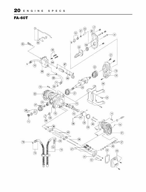
E N G I N E S P E C S20FA-60T
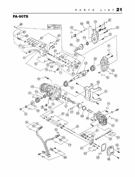
P A R T S L I S T 21FA-90TS
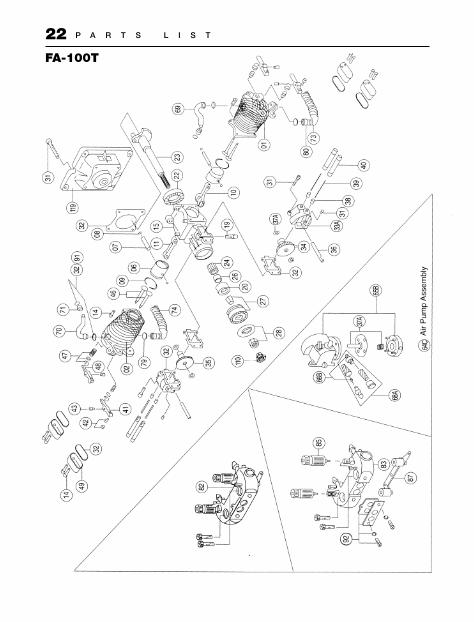
P A R T S L I S T22FA-100T
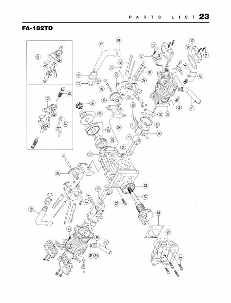
P A R T S L I S T 23FA-182TD
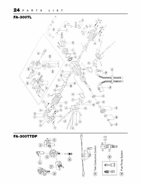
P A R T S L I S T24FA-300TL
FA-300TTDP

P A R T S L I S T 25
Saito engines are guaranteed against workmanship and manufacturing defects for a period of 3 years from the original date of purchase. This warranty is limited to the original purchaser of the engine and is not transferable. Warranty repairs will not cover:• Normal engine wear• Damage due to insufficient
maintenance• Damage related to overrevving of
engine due to small prop size or unreasonable use
• Rusted bearings
• Crash damage• Damage due to use of improper fuel
and/or glow plug• Damage due to lean runs such as
rusted bearings, seized connecting rod or piston, etc.
• Damage caused by foreign objects (dirt or broken glow plug filaments)
• Damage caused by unreasonable mounting or running conditions (dust, insufficient cooling, improper mounting, improper propeller size or lack of balancing, etc.)
• Damage due to improper disassembly• Modifications of any kind
Consumer Warranty and Repair Policy
If your engine needs repair, please do the following:1. Ship your engine, freight prepaid, in its original box packed inside a sturdy shipping container, to:
Horizon Service CenterAttn: Saito Service4105 Fieldstone RoadChampaign, IL 61822Phone:(217)355-9511
Include complete name and address information inside the carton, as well as clearly writing it on the outer label/return address area.
2. Include a note containing a brief summary of the difficulty experienced and include the following information:
• Nitro content and brand of fuel• Propeller size and brand used• Type of glow plug used• Type of engine mount• Approximately how much running
time the engine had before experiencing the difficulty
Date your correspondence and be sure your name and address appear on this enclosure. Also, include a phone number where you can be reached during the business day.
W A R R A N T Y & R E P A I R26
3. Warranty Repairs
To receive warranty service you must include your original dated sales receipt to verify your proof-of-purchase date. Providing that warranty conditions have been met, your engine will be repaired without charge.
4. Non-Warranty Repairs
Should your repair cost exceed 50% of the retail purchase cost, you will be provided with an estimate advising you of your options. Any return freight for non-warranty repairs will be billed to the consumer.
5. Please advise us of the paymentmethod you prefer to use. Please specify VISA or MasterCard, or we can return C.O.D. cash only. If you prefer to use a credit card, include your card number and expiration date.
The consumer warranty registration card in this manual must be completely filled out and mailed to:
Horizon Service CenterAttn: Saito Warranty4105 Fieldstone RoadChampaign, IL 61822

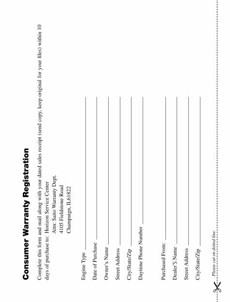
Consu
mer
Warr
anty
Regis
trati
on
Com
plet
e th
is f
orm
and
mai
l al
ong
with
you
r da
ted
sale
s re
ceip
t (s
end
copy
, kee
p or
igin
al f
or y
our
fi les
) w
ithin
10
days
of
purc
hase
to:
Hor
izon
Ser
vice
Cen
ter
A
ttn: S
aito
War
rant
y D
ept.
41
05 F
ield
ston
e R
oad
C
ham
paig
n, I
L61
822
Eng
ine
Type
Dat
e of
Pur
chas
e
Ow
ner 's
Nam
e
Stre
et A
ddre
ss
City
/Sta
te/Z
ip
Day
time
Phon
e N
umbe
r
Purc
hase
d Fr
om:
Dea
ler 'S
Nam
e
Stre
et A
ddre
ss
City
/Sta
te/Z
ip
Ple
ase
cut o
n do
tted
line
.


Exclusively Distributed by Horizon Hobby, Inc.
Champaign, IL61822
© Copyright 2006 Stock#SAIMAN2