Embed Size (px)
Citation preview
Supplied By www.heating spares.co Tel. 0161 620 6677
Installation
& Servicing
Instructions
THESE INSTRUCTIONSTO BE RETAINEDBY USER
Vokèra is a licensed member of the Benchmark schemewhich aims to improve the standards of installation and commissioning of domestic hot water systems in the UK.
AquaFlow Single coil water cylinder
AquaFlow Twin Twin coil water cylinder

Supplied By www.heating spares.co Tel. 0161 620 6677
-1-
PLEASE LEAVE THIS MANUAL WITH THE UNIT AFTER INSTALLATION
0014
2046
-00
INSTALLATION MANUAL This manual gives detailed advice for installation and should be read carefullyprior to fitting any unvented unit. This Vokera Aquaflow cylinder must be installedby a competent person and be installed in compliance with the Vokera AquaflowInstallation and Maintenance Instructions, all current legislation, codes of practiceand regulations governing the installation of unvented hot water cylinders in force at the date of installation.
Components supplied with the unit for site fitting (See also page 2/3 for component list)
* Multibloc valve, includes pressure reducing valve, line strainer, balanced cold water take off, (forshower or bidet only) check and expansion valve.
Health and Safety Manual Handling Operations Regulations 1992 defines manualhandling as: "any transporting or supporting of a load (including thelifting, putting down, pushing, pulling, carrying or moving thereof) byhand or bodily force" The Regulations set no specific requirementssuch as weight limits. However common sense still has to be usedbased on an ergonomic approach for each individual
DIMENSION AND WEIGHTS TABLE 1PRODUCT REF. 150 200 250 210T 250T
HEIGHT 900 1150 1600 1400 1600
DIAMETER 580 580 580 580 580
WEIGHT EMPTY 40 48 64 60 64
COIL RATING KW 12 26 26
UPPER COIL 12 12
LOWER COIL 12 26
* Tundish. * 1/2"F x 15 x 15 tee piece. * Flexible hose.* 3/4" x 22 mm Elbow / Drain Cock* Commissioning valve, 1/2" BSP male.* Motorized valve.* Expansion vessel
Components factory fitted * Immersion heater(s).* Thermostats / thermal cut-out. * Temperature and pressure relief valve.
Installation details The Vokera unvented unit is designed for use with supply pressure up to 16 bar. For pressuresover 16 bar an additional pressure reducing valve must be fitted in the supply pipe to the unit. Wall mounting brackets are available for Vokera Aquaflow unvented units 120-200 litres capacity.
Aquaflow 150 - 200 - 250
AquaFlow Twin 210 - 250

General Layout Fig: 1
1 Flow ¾" 2 Return ¾"
3 Pressure ReIncludes Item
4 Check and E5 Temperature
Relief Valve6 Tundish 7 Immersion H
7A Thermostat Thermostat
8 Cold Feed T(Not Supplie
9 Hot Water O
TASeries Len
120
150
200
99
Supplied By www.heatin
KEY Part No KEY Part No BSPF 10 Flexible Hose 202108 BSPF 11 Secondary Return ½”BSPF
Fit ½"Fx½"Mx15mm Tee piece (Not supplied)
ducing Valve 4
510503 12 Commisioning Valve / Fitting (½" MI Drain Cock)
250440
xpansion Valve 510505 13 Elbow / Drain Cock 250445 and Pressure
550803 14 Cable Entry
219002 15 Electrical Box eater 71255 16 Tee Piece 250006
Immersion Heater Cylinder
80400 80511
17 Discharge Pipe (Not supplied)
ube d See Table 2)
18 Motorised Valve Not Factory Fitted)
92000
utlet 22mm
BLE 2 gth of tube (ø22) mm
480 mm
585 mm
760 mm
INDIRECT
22 22
RESETRESET
11
11
22
331133
44
11
4422
RESETRESET
7
5
12
2
1415
118
16
13
7a
8
6
17
105
4
3
11
g spares.co Tel. 0161 620 6677
-2-

Supplied By www.heating spares.co
-3-
General Layout Fig: 1A
KEY Part No 1
1A Return ¾" BSP Return ¾" BSP
10 F
2 2A
Flow ¾" BSP Flow ¾" BSP
11 SFsu
3 Pressure Reducing Valve Includes Item 4
510503 12 C(½
4 Check and Expansion Valve 510505 13 E5 Temperature and Pressure
Relief Valve 550803 14 C
6 Tundish 219002 15 E7
7A Immersion Heater Immersion Heater Thermostat
71255 80020
16 T
7B 7C
Thermostat Boiler Thermostat Solar
80030 80030
17 D
8 Cold Feed Tube (Not Supplied See Table 2)
18 M
9 Hot Water Outlet 22mm 19 S 20 D
2
Tel. 0161 620 6677
KEY Part No lexible Hose 202108
econdary Return ½”BSPF it ½"Fx½"Mx15mm Tee piece (Not pplied)
ommissioning Valve / Fitting " MI Drain Cock)
250440
lbow / Drain Cock 250445 able Entry
lectrical Box ee Piece 250006
ischarge Pipe (Not supplied)
otorised Valve Not Factory Fitted)
92000
olar Sensor Bosses ip Pipe (removable)
0

Supplied By www.heating spares.co Tel. 0161 620 6677
-4-
COLD WATER SUPPLY 1. To obtain the best performance from your Aquaflow unvented system it is advisable to feed
the unit with an uninterrupted supply. 2. Locate the water heater in a suitable position to facilitate the installation of the cold water
supply, discharge fittings and pipework. Also take into account access to the immersion heaters and the commissioning valve.
3. Fit the combined male elbow / drain cock to cold supply point (13), so that the compression fitting is vertical. 4. Fit the commissioning valve (12) to the commissioning fitting. 5. Fit both ½” male solar sensor pockets to the Solar Sensor bosses (19). 6. Fit the female outlet of the tee piece to the temperature and pressure relief valve (5) with the
horizontal connection facing right at approx. 45°. 7. Fit the tundish (6) to the tee piece using a short length of 15 mm copper tube. 8. Fit the length of copper tube 22mm specified in Table 2 to the cold feed elbow (see 3 above). 9. Fit the pressure reducing valve (3) to the top of the copper tube (see 7 above), so that the
black knob is facing right. 10. Connect the flexible hose to the 1/2" outlet of the expansion valve (4) and the horizontal outlet
of the tee piece (see 5 above). Discard compression nut & ring. 11. If a balanced mains pressure cold water supply is required to a shower or bidet (over rim
type only, ascending spray type requires type AA,AB or AD air gap), remove the blanking cap from the pressure reducing valve (3) and connect to the shower or bidet cold supply. (Major shower manufacturers advise fitting a mini expansion vessel in the balanced cold supply pipework to accommodate thermal expansion and prevent tightening of shower controls) Using the balanced cold connection to feed bath taps can reduce the flow available to the unvented cylinder.
12. Before connecting the cold supply, flush the cold supply pipework of all flux and debris. 13. Connect the cold supply to the pressure reduction valve (Multibloc) (3). Hot water supply 14. Connect the hot water supply pipe to the outlet (9). Ensure connection is water tight.
Secondary return 15. A secondary return facility is provided on all units. Fit a ½” F x ½” M x 15mm tee piece
between the commissioning valve (12) and the commissioning fitting. See also figure 4 on page 16.
Discharge pipe 16. Connect the discharge pipe from the tundish (6.) This must have a continuous fall and be
fitted in accordance with The Building Regulations (see pages 5 and 12).
Supplied By www.heating spares.co Tel. 0161 620 6677
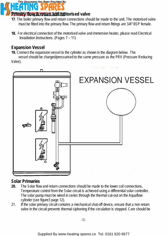
Primary flow & return and motorised valve 17. The boiler primary flow and return connections should be made to the unit. The motorised valve must be fitted into the primary flow. The primary flow and return fittings are 3/4" BSP female. 18. For electrical connection of the motorised valve and immersion heater, please read Electrical Installation Instructions. (Pages 7 – 11) Expansion Vessel 19. Connect the expansion vessel to the cylinder as shown in the diagram below. The vessel should be charged/pressurised to the same pressure as the PRV (Pressure Reducing Valve).
Solar Primaries 20. The Solar flow and return connections should be made to the lower coil connections. Temperature control from the Solar circuit is achieved using a differential solar controller. The solar pump must be wired in series through the thermal cut-out on the Aquaflow cylinder (see figure3 page 12). 21. If the solar primary circuit contains a mechanical shut-off device, ensure that a non return valve in the circuit prevents thermal siphoning if the circulation is stopped. Care should be
-5-

Supplied By www.heating spares.co Tel. 0161 620 6677
-6-
taken to ensure the device is suitable for temperatures and fluids that may be present in a solar-thermal system. 22. Temperature sensors for the cylinder provided with the differential controller should be inserted into the pockets provided see figure 1A.
COMMISSIONING Filling up 1. Open one hot water tap. 2. Close the commissioning valve (12). 3. Open the cold water supply valve. 4. When water flows from the open hot tap allow to flow to expel air from the system pipe work. 5. Open each hot water tap in turn to expel air from the system pipe work. 6. Check for leaks. 7 Manually operate Temperature and Pressure Relief Valve (5) to ensure free water flow through discharge pipe.(Turn knob to left.) Draining Switch off the electrical power off (Important to avoid damage to element). Isolate boiler from Aquaflow unit. Turn off the cold water supply valve. Open hot water tap. Open drain (13). The unit will drain.
SAFETY AND MAINTAINANCE Safety Cut-out 1. The safety cut-out operates if: a. Wiring is incorrect. b. The immersion heater thermostat or cylinder thermostat fails. c. Thermostat is set too high. 2. Remember before resetting the safety cut-out or altering the thermostat setting, isolate
electrical supply to the unit prior to removal of the electrical box lid. 3. Reduce thermostat setting and press the reset button. After adjustments are completed, ensure
the lid to the electrical box is replaced correctly and the retaining screw is fitted. 4. If still out of operation, contact installer. Cold or tepid water discharge from tundish 1. Turn off the electrical supply to the immersion heaters. 2. Turn off cold water supply valve. 3. Open a hot tap. 4. Recharge the expansion vessel to the setting of the pressure reducing valve. 5. Close all hot taps. 6. Open mains supply valve

Supplied By www.heating spares.co Tel. 0161 620 6677
-7-
7. Open and close a hot tap to ensure continuity of supply 8. Turn on electrical supply to the immersion heaters. Hot water discharge from tundish This indicates a malfunction of a thermal cut-out, operating thermostat or the combined temperature and pressure relief valve. Turn off the electrical supply to the immersion heater and also isolate an indirect unit from the boiler. Contact the installer or competent engineer.
INSTALLATION AND SERVICING INSTRUCTIONS Cold water inlet control (Multibloc) See Page 2/3 Items 3 - 4 This combination consists of a pressure reducing valve with integral strainer, check valve and expansion valve with stainless steel seat. The pressure settings are set and locked in the factory and are shown on the top of each valve. For optimum performance the following installation instructions should be complied with. Installation 1. Cold water supply to be 22 mm nominal size. 2. Flush supply pipework before connection to remove all flux and debris prior to fitting the inlet
controls. Failure to do this may result in irreparable damage to the controls and will invalidate the warranty.
3. The "MULTIBLOC" can be fitted in any orientation to suit the installation as long as it is fitted in the correct flow direction. Check the flow arrows on the side of the body.
4. The expansion valve should be either horizontal or upright - if fitted inverted, debris may be deposited on the seat and cause fouling of the seat when the valve operates. Check direction of flow arrows.
5. The black plastic plugs in the body are pressure gauge connections to enable pressure monitoring to be carried out, should the system develop a fault. It is recommended that these be accessible (the pressure reducing valve has two - only one need be accessible).
6. Expansion relief drain pipework must be connected to a safe visible discharge point via a tundish and the pipework must have a continuous fall.
7. The pressure reducing valve has two outlets, the second one is for a balanced cold water supply, to a shower or a bidet (over rim type only, ascending spray type requires type AA,AB or AD air gap) (Major shower manufacturers advise fitting a mini expansion vessel in the balanced cold supply pipework to accomodate thermal expansion and prevent tightening of shower controls) Using the balanced cold connection to feed bath taps can reduce the flow available to the unvented cylinder. The balanced cold supply is blanked off.
NOTE: If the unit has been commissioned and is to be unused for more than 8 weeks it is advisable to turn off the cold supply and draw off approximately 5 litre of water through a hot tap. NB The cold supply must be opened prior to use. The Benchmark Log Book enclosed with the cylinder should be completed after commissioning the system and handed to the customer for future reference.

Su
MAINTENANCE Under normal circumstances the "MULTIBLOC" combination control valve should not require any maintenance. However, annual inspection and / or cleaning of the integral line strainer, pressure reducing valve, cartridge, expansion relief valve cartridge and seating may be necessary depending on local water conditions. Pressure reducing valve 1. Isolate cold water supply. 2. Unscrew the retaining nut of the valve.
The complete operating mechanism, including the strainer can be removed.
3. Clean the filter mesh and the cartridge under running water.
4. Replace cartridge ensuring that strainer is correctly located and reassemble the unit. Pressure Reducing Valve cartridge and strainer Part No. 510 501 2.1 Bar.
Expansion relief cartridge 1. Isolate cold water supply. 2. Unscrew blue expansion relief headwork
from valve body. 3. Clean valve seat face and seating - do not
scratch or damage either seal face or seating. 4. Refit in reverse order. Do not overtighten.
Expansion valve cartridge and seat Part No. 214009 8.0 Bar. Complete Expansion Valve Part No. 510 505 8.0 Bar.
Tundish Install the Tundish iPressure Relief Valvthe tundish. Tundishtundish. Maximum p0.8 m of pipework. Aany doubt, refer to B
Spare Parts Expansion valve (Cartridge) Part No. 8.0 Bar 214009 6.0 Bar 214005 4.0 Bar 214046
Expansion valve
Pressure reducing valve Cartridge and strainer Part No. 510 501 2.1Bar
pplied By www.heating spares.co Tel. 0161 620 6677
-8-
n a vertical position within a maximum of 500 mm from the Temperature and e drain connection. Ensure the expansion relief pipework discharges through pipework must be 22 mm with a minimum vertical length of 300 mm below
ermitted length of 22 mm pipework is 9 m. Each bend or elbow is equivalent to ll pipework must have continuous fall and discharge in a safe, visible position. If uilding Regulation G3.
Part No. 510 505 8.0Bar

Supplied By www.heating spares.co Tel. 0161 620 6677
-9-
ELECTRICAL INSTALLATION Immersion heaters All units are fitted with one immersion heater which is located behind the electrical box. Indirect Units Upper Coil Motorised valve To comply with regulations governing the installation of indirect unvented cylinders, a motorised valve must be fitted in the primary flow. Your Aquaflow unit has been supplied with a two port motorised valve, which will act as a positive energy cut-out should the safety cut-out operate. The motorised valve will also control the temperature of the domestic stored water via the cylinder thermostat, which is located in the electrical box. The unit should be installed on an "S" or "Y" plan system. Cylinder temperature control can also be achieved via the solar thermostat when the boiler is not operational. Please follow the instructions carefully. All electrical connections must conform to current IEE wiring regulations. The working thermostat which controls the temperature of the domestic hot water (see fig. 2/2A/2B/2C) is adjustable between 45°C - 75°C. A safety cut out is also incorporated within the thermostat and will operate at 85°C ± 3°C. Should the safety cut out be brought into operation, the motorised valve will operate and close down the primary flow to the cylinder. To reset the safety cut-out and the motorised valve the reset button must be pressed in (see fig. 2/2A/2B/2C).If using a 6-wire 28mm or 1” BSP V4043H on either circuit the white wire is not needed and must be made electrically safe. Lower (Solar) coil Heat sources to unvented hot water cylinders must be controlled by a thermal cut-out as well as a thermostat. The Aquaflow Twin is supplied both with bosses for solar sensor pockets and the pockets themselves. The top half of the thermostats fitted to the cylinder is a thermal cut-out. The solar controller (not supplied) and solar sensor point should be wired through the Aquaflow Twin Thermal cut-out. Please note that the direction of flow in the solar coil is reversed compared to the boiler coil. If the cylinder is not being used for solar use, connect the lower coil according to the instructions for the upper coil. Vokera can not be responsible if alternative wiring plans are used. Important: Before resetting the safety cut-out or altering the thermostat setting isolate electrical supply to the unit before removal of the lid.

Supplied By www.heating spares.co Tel. 0161 620 6677
-10-
’S’ Plan systems Refer to the wiring diagrams contained within the boiler installation instructions for the wiring of ’S’-
Plan systems. Connect the cylinder thermostat as shown in the diagram below
S Plan System Schematic 2A

Supplied By www.heating spares.co Tel. 0161 620 6677
-11-
Y Plan Wiring Layout Refer to the wiring diagrams contained within the boiler installation instructions for the wiring of ’Y’-Plan systems. Connect the cylinder thermostat as shown in the diagram below. NOTE A 10 way junction box must be used on the Y plan system.
B
Y Plan System Schematic
2C
Supplied By www.heating spares.co Tel. 0161 620 6677
-12-
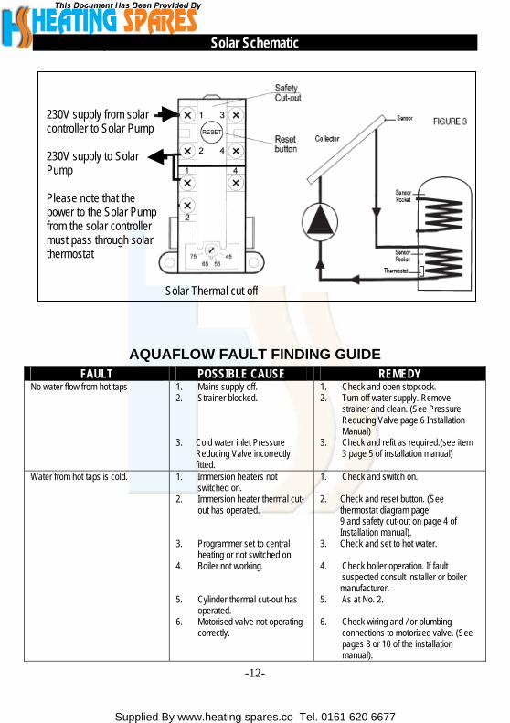
Solar Schematic
230V supply from solar controller to Solar Pump 230V supply to Solar Pump Please note that the power to the Solar Pump from the solar controller must pass through solar thermostat
Solar Thermal cut off
AQUAFLOW FAULT FINDING GUIDE FAULT POSSIBLE CAUSE REMEDY
No water flow from hot taps 1. Mains supply off. 2. Strainer blocked. 3. Cold water inlet Pressure Reducing Valve incorrectly fitted.
1. Check and open stopcock. 2. Turn off water supply. Remove
strainer and clean. (See Pressure Reducing Valve page 6 Installation Manual)
3. Check and refit as required.(see item 3 page 5 of installation manual)
Water from hot taps is cold. 1. Immersion heaters not switched on.
2. Immersion heater thermal cut-out has operated.
3. Programmer set to central
heating or not switched on. 4. Boiler not working. 5. Cylinder thermal cut-out has
operated. 6. Motorised valve not operating
correctly.
1. Check and switch on. 2. Check and reset button. (See thermostat diagram page 9 and safety cut-out on page 4 of Installation manual). 3. Check and set to hot water. 4. Check boiler operation. If fault
suspected consult installer or boiler manufacturer. 5. As at No. 2. 6. Check wiring and / or plumbing
connections to motorized valve. (See pages 8 or 10 of the installation manual).

Supplied By www.heating spares.co Tel. 0161 620 6677
Intermittent water discharge. 1. Reduced expansion capacity. 2. Thermal control failure. (Note Water will be hot).
1. Recharge expansion vessel to correct charge (same as pressure reducing valve).
2. Switch off power to immersion heater(s) and boiler supply to the unit. When discharge has stopped, check thermal controls, replace if faulty. Contact a competent person.
Continuous water discharge. 1. Cold water inlet Pressure Reducing Valve not working. 2. Temperature and pressure
relief valve faulty. 3. Expansion relief valve not
working correctly.
1. Check pressure from valve if greater than 2.1 bar replace. (See page 6 of installation manual)
2. As No. 2 of above. 3. Check and replace if faulty. (See page 6 of installation manual).
NOTE: Disconnect electrical supply before removing any electrical equipment covers.
AQUAFLOW FAULT FINDING GUIDE
-13-

Supplied By www.heating spares.co Tel. 0161 620 6677
-14-

Supplied By www.heating spares.co Tel. 0161 620 6677
-15-

Supplied By www.heating spares.co Tel. 0161 620 6677
-16-
Notes:
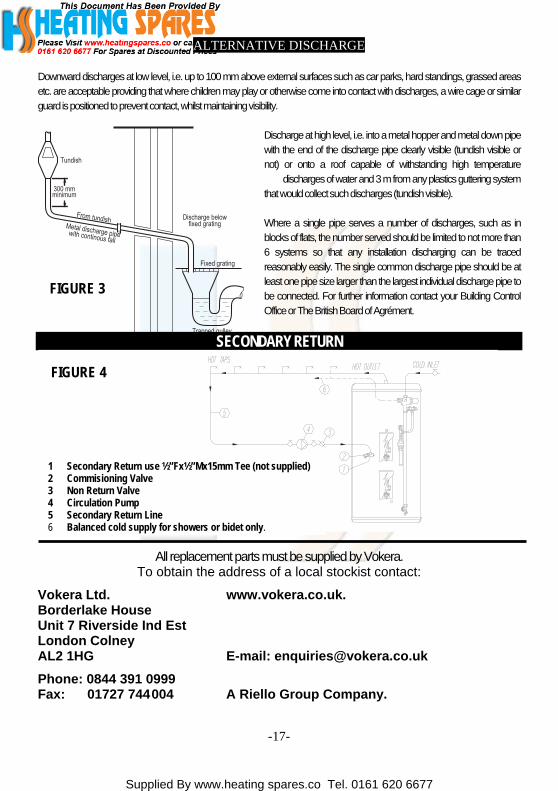
ALTERNATIVE DISCHARGE
Downward discharges at low level, i.e. up to 100 mmabove external surfaces such as car parks, hard standings, grassed areasetc. areacceptable providing thatwhere childrenmayplay orotherwise come into contactwith discharges,awire cageor similarguardis positioned to preventcontact, whilst maintainingvisibility.
Discharge at high level, i.e. intoa metalhopper and metaldown pipewith the end of the discharge pipe clearly visible (tundish visible ornot) or onto a roof capable of withstanding high temperature
dischargesof waterand 3 m from anyplastics guttering systemthat would collectsuch discharges(tundishvisible).
Where a single pipe serves a number of discharges, such as in blocks of flats, the number served shouldbe limited to not more than 6 systems so that any installation discharging can be tracedreasonably easily. The single common discharge pipe should be atleastone pipe size larger thanthe largest individualdischargepipe tobe connected. For further information contact your Building ControlOfficeor TheBritish Board of Agrément.
SECONDARY RETURN
FIGURE 3
VBULA
PF
FIGURE 4
1 Sec2 Com3 Non4 Circ5 Sec6 Bala
okeraordernit 7 RondonL2 1H
hone:ax:
ondary Return use ½”Fx½”Mx15mm Tee (not supplied)misioning Valve
Return Valveulation Pump ondary Return Linenced cold supply for showers or bidet only.
Supplied By www.heating spares.co Tel. 0161 620 6677
All replacementparts must be supplied by Vokera.To obtain the address of a local stockist contact:
Ltd. www.vokera.co.uk.lake Houseiverside Ind Est ColneyG E-mail: [email protected]
0844 391 0999 01727 744004 A Riello Group Company.
-17-
Supplied By www.heating spares.co Tel. 0161 620 6677
Registered address:Vokèra Ltd
Borderlake HouseUnit 7 Riverside Industrial Estate
London ColneyHerts AL2 1HG
www.vokera.co.ukwww.vokera.ie
Sales, General EnquiresT 0844 391 099
F 0844 391 0998
Vokèra IrelandWest Court, Callan
Co KilkennyT 056 7755057F 056 7755060
Vokèra Limited reserve the right to changespecification without prior notice
Consumers statutory rights are not affected.
A Riello Group Company.Company Reg No: 1047779