Embed Size (px)
Citation preview
TVCG-2013-10-0283 1
Smooth Rotation EnhancedAs-Rigid-As-Possible Mesh Animation
Zohar Levi and Craig Gotsman
Abstract—In recent years, the As-Rigid-As-Possible (ARAP) shape deformation and shape interpolation techniques gained popularity,and the ARAP energy was successfully used in other applications as well. We improve the ARAP animation technique in two aspects.First, we introduce a new ARAP-type energy, named SR-ARAP, which has a consistent discretization for surfaces (triangle meshes).The quality of our new surface deformation scheme competes with the quality of the volumetric ARAP deformation (for tetrahedralmeshes). Second, we propose a new ARAP shape interpolation method that is superior to prior art also based on the ARAP energy.This method is compatible with our new SR-ARAP energy, as well as with the ARAP volume energy.
Index Terms—As-Rigid-As-Possible (ARAP), shape deformation, shape interpolation
F
1 INTRODUCTION
To animate a 3D mesh, a modeler typically uses amesh deformation tool to create new poses and a shapeinterpolation tool to generate the frames between theposes. A shape interpolation tool is also useful in otherapplications such as example-based deformation [4], [5],or morphing sequence generation by interpolation oftwo different meshes having a common topology [6].While Linear Blending Skin (LBS) is the most popu-lar animation technique, it suffers from a number ofdrawbacks. The main ones are the low quality of thedeformation in terms of local shape preservation nearjoints (e.g. the well known “candy-wrapper” effect); thetedious task of painting the skin weights; and the needto bind a skeleton, which limits the deformation toarticulated motion, thus preventing its use for intuitivefreeform deformation. Many alternatives to LBS havebeen proposed, and in terms of user interface, the mostconvenient ones let the user manipulate handle points,and the rest of the mesh is automatically deformed in anatural way. Afterwards, a shape interpolation methodis applied to create a natural animation between poses.The methods in [7], [2], [3] introduced an animationtechnique based on minimizing the so-called As-Rigid-As-Possible (ARAP) energy. The ARAP energy measuresthe local deviation of the differential of a mappingbetween two shapes from rigidity, shown to be ad-vantageous for detail preservation and intuitive elasticbehavior. The attractiveness of ARAP methods is inthe simplicity of their formulation (built upon classicalLaplacian mesh editing techniques), and not requiringany additional accessories or constructions. These leadto an easy implementation, while producing compellingresults (at least for the volumetric case, as discussed
• Zohar Levi and Craig Gotsman are with the Technion, Israel.
later on). Another feature of the ARAP energy is itsability to be easily converted to As-Similar-As-Possibleenergy, which produces, for example, a quasi-conformalmapping [8], [9]. Thus, it is not surprising that the ARAPenergy became popular and has been used successfullyin other applications such as parametrization [9], imageregistration [10], [11], shape decomposition [12], cage-based deformation [13], image warping [14], [15], andvideo stabilization [16]. Like many surface variationaldeformation methods, one drawback of the ARAP defor-mation method is performance; only coarse meshes canbe deformed at interactive rates. One popular solutionis using a hierarchical-based approach [17].
Given two meshes P and Q consisting of vertices piand qi respectively, and directed edges pij (= pj − pi)and qij , the discrete ARAP energy is defined as:
E(P,Q) =
m∑k=1
minRk∈SO(3)
∑(i,j)∈Ek
cijk‖qij −Rkpij‖2 , (1)
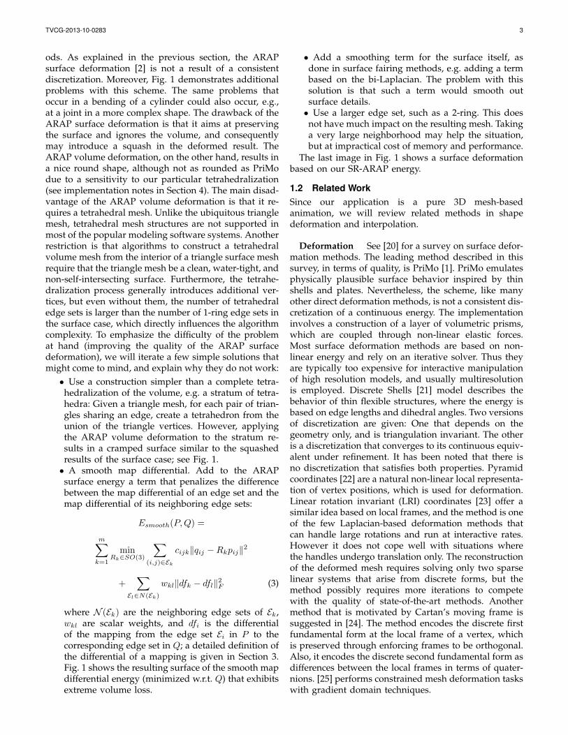
where R1, ..., Rm ∈ SO(3) are optimal local rotations;E1, ..., Em are their corresponding edge sets, typicallythe edges of a triangle, a tetrahedron, or a vertex 1-ring (see Fig. 2); and cijk are weighting coefficients,typically uniform or the familiar cotan weights. In theshape deformation setup, deforming a mesh P involvesfixing handle points and solving for the rest of theqi by minimizing (1). The intuition for minimizing theARAP energy is to find a mesh Q that is locally a rigidtransformation of the source mesh P . More specifically,the differential of a mapping from an edge set in P toa corresponding edge set in Q should be optimally arotation, thus synchronizing corresponding edge vectorsof the two edge sets. For example, if the positional con-straints allow for Q to be a global rigid transformationof P , then all the Rk would be equal, and the energywould be zero.
While previous applications in 3D used the discrete
TVCG-2013-10-0283 2
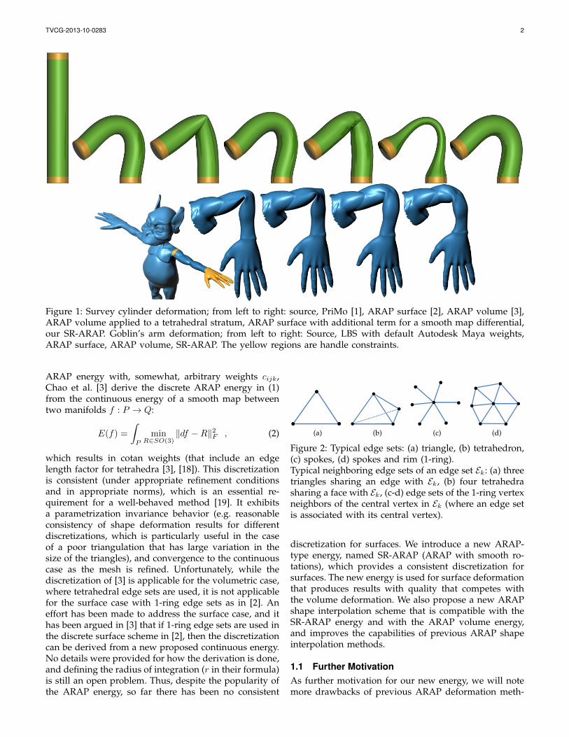
Figure 1: Survey cylinder deformation; from left to right: source, PriMo [1], ARAP surface [2], ARAP volume [3],ARAP volume applied to a tetrahedral stratum, ARAP surface with additional term for a smooth map differential,our SR-ARAP. Goblin’s arm deformation; from left to right: Source, LBS with default Autodesk Maya weights,ARAP surface, ARAP volume, SR-ARAP. The yellow regions are handle constraints.
ARAP energy with, somewhat, arbitrary weights cijk,Chao et al. [3] derive the discrete ARAP energy in (1)from the continuous energy of a smooth map betweentwo manifolds f : P → Q:
E(f) =
∫P
minR∈SO(3)
‖df −R‖2F , (2)
which results in cotan weights (that include an edgelength factor for tetrahedra [3], [18]). This discretizationis consistent (under appropriate refinement conditionsand in appropriate norms), which is an essential re-quirement for a well-behaved method [19]. It exhibitsa parametrization invariance behavior (e.g. reasonableconsistency of shape deformation results for differentdiscretizations, which is particularly useful in the caseof a poor triangulation that has large variation in thesize of the triangles), and convergence to the continuouscase as the mesh is refined. Unfortunately, while thediscretization of [3] is applicable for the volumetric case,where tetrahedral edge sets are used, it is not applicablefor the surface case with 1-ring edge sets as in [2]. Aneffort has been made to address the surface case, and ithas been argued in [3] that if 1-ring edge sets are used inthe discrete surface scheme in [2], then the discretizationcan be derived from a new proposed continuous energy.No details were provided for how the derivation is done,and defining the radius of integration (r in their formula)is still an open problem. Thus, despite the popularity ofthe ARAP energy, so far there has been no consistent
(a) (b) (c) (d)
Figure 2: Typical edge sets: (a) triangle, (b) tetrahedron,(c) spokes, (d) spokes and rim (1-ring).Typical neighboring edge sets of an edge set Ek: (a) threetriangles sharing an edge with Ek, (b) four tetrahedrasharing a face with Ek, (c-d) edge sets of the 1-ring vertexneighbors of the central vertex in Ek (where an edge setis associated with its central vertex).
discretization for surfaces. We introduce a new ARAP-type energy, named SR-ARAP (ARAP with smooth ro-tations), which provides a consistent discretization forsurfaces. The new energy is used for surface deformationthat produces results with quality that competes withthe volume deformation. We also propose a new ARAPshape interpolation scheme that is compatible with theSR-ARAP energy and with the ARAP volume energy,and improves the capabilities of previous ARAP shapeinterpolation methods.
1.1 Further MotivationAs further motivation for our new energy, we will notemore drawbacks of previous ARAP deformation meth-
TVCG-2013-10-0283 3
ods. As explained in the previous section, the ARAPsurface deformation [2] is not a result of a consistentdiscretization. Moreover, Fig. 1 demonstrates additionalproblems with this scheme. The same problems thatoccur in a bending of a cylinder could also occur, e.g.,at a joint in a more complex shape. The drawback of theARAP surface deformation is that it aims at preservingthe surface and ignores the volume, and consequentlymay introduce a squash in the deformed result. TheARAP volume deformation, on the other hand, results ina nice round shape, although not as rounded as PriModue to a sensitivity to our particular tetrahedralization(see implementation notes in Section 4). The main disad-vantage of the ARAP volume deformation is that it re-quires a tetrahedral mesh. Unlike the ubiquitous trianglemesh, tetrahedral mesh structures are not supported inmost of the popular modeling software systems. Anotherrestriction is that algorithms to construct a tetrahedralvolume mesh from the interior of a triangle surface meshrequire that the triangle mesh be a clean, water-tight, andnon-self-intersecting surface. Furthermore, the tetrahe-dralization process generally introduces additional ver-tices, but even without them, the number of tetrahedraledge sets is larger than the number of 1-ring edge sets inthe surface case, which directly influences the algorithmcomplexity. To emphasize the difficulty of the problemat hand (improving the quality of the ARAP surfacedeformation), we will iterate a few simple solutions thatmight come to mind, and explain why they do not work:• Use a construction simpler than a complete tetra-hedralization of the volume, e.g. a stratum of tetra-hedra: Given a triangle mesh, for each pair of trian-gles sharing an edge, create a tetrahedron from theunion of the triangle vertices. However, applyingthe ARAP volume deformation to the stratum re-sults in a cramped surface similar to the squashedresults of the surface case; see Fig. 1.• A smooth map differential. Add to the ARAPsurface energy a term that penalizes the differencebetween the map differential of an edge set and themap differential of its neighboring edge sets:
Esmooth(P,Q) =
m∑k=1
minRk∈SO(3)
∑(i,j)∈Ek
cijk‖qij −Rkpij‖2
+∑
El∈N(Ek)
wkl‖dfk − dfl‖2F (3)
where N (Ek) are the neighboring edge sets of Ek,wkl are scalar weights, and dfi is the differentialof the mapping from the edge set Ei in P to thecorresponding edge set in Q; a detailed definition ofthe differential of a mapping is given in Section 3.Fig. 1 shows the resulting surface of the smooth mapdifferential energy (minimized w.r.t. Q) that exhibitsextreme volume loss.
• Add a smoothing term for the surface itself, asdone in surface fairing methods, e.g. adding a termbased on the bi-Laplacian. The problem with thissolution is that such a term would smooth outsurface details.• Use a larger edge set, such as a 2-ring. This doesnot have much impact on the resulting mesh. Takinga very large neighborhood may help the situation,but at impractical cost of memory and performance.
The last image in Fig. 1 shows a surface deformationbased on our SR-ARAP energy.
1.2 Related WorkSince our application is a pure 3D mesh-basedanimation, we will review related methods in shapedeformation and interpolation.
Deformation See [20] for a survey on surface defor-mation methods. The leading method described in thissurvey, in terms of quality, is PriMo [1]. PriMo emulatesphysically plausible surface behavior inspired by thinshells and plates. Nevertheless, the scheme, like manyother direct deformation methods, is not a consistent dis-cretization of a continuous energy. The implementationinvolves a construction of a layer of volumetric prisms,which are coupled through non-linear elastic forces.Most surface deformation methods are based on non-linear energy and rely on an iterative solver. Thus theyare typically too expensive for interactive manipulationof high resolution models, and usually multiresolutionis employed. Discrete Shells [21] model describes thebehavior of thin flexible structures, where the energy isbased on edge lengths and dihedral angles. Two versionsof discretization are given: One that depends on thegeometry only, and is triangulation invariant. The otheris a discretization that converges to its continuous equiv-alent under refinement. It has been noted that there isno discretization that satisfies both properties. Pyramidcoordinates [22] are a natural non-linear local representa-tion of vertex positions, which is used for deformation.Linear rotation invariant (LRI) coordinates [23] offer asimilar idea based on local frames, and the method is oneof the few Laplacian-based deformation methods thatcan handle large rotations and run at interactive rates.However it does not cope well with situations wherethe handles undergo translation only. The reconstructionof the deformed mesh requires solving only two sparselinear systems that arise from discrete forms, but themethod possibly requires more iterations to competewith the quality of state-of-the-art methods. Anothermethod that is motivated by Cartan’s moving frame issuggested in [24]. The method encodes the discrete firstfundamental form at the local frame of a vertex, whichis preserved through enforcing frames to be orthogonal.Also, it encodes the discrete second fundamental form asdifferences between the local frames in terms of quater-nions. [25] performs constrained mesh deformation taskswith gradient domain techniques.
TVCG-2013-10-0283 4
Sorkine et al. [2] propose a surface deformationbased on the ARAP energy. Chao et al. [3] derive asimilar ARAP formulation from the continuous casefor volume deformation. [26], [8] base their ARAPdeformation scheme on the Moving Least Squares(MLS) approach. Borosan et al. [13] introduce a hybridapproach that couples a surface deformation with acage-based deformation. The user can perform editson an automatically-generated simplified version of aninput shape using ARAP surface modeling. The editis propagated to the original shape by a precomputedspace deformation based on Mean Value Coordinates.Manson et al. [17] build a low-resolution representationof a mesh by using edge collapses, and perform anARAP deformation on the simplified mesh. Then detailsare added back by reversing edge-collapses, so that theshape of the mesh is locally preserved. While addingdetails, the mesh is deformed to match the predictedpositions of constraints, so that constraints on the full-resolution mesh are met. Zollhofer et al. [27] presenta novel lattice-based mesh editing that decouplesthe runtime complexity from the mesh geometriccomplexity. Its non-linear optimization minimizes anARAP energy and is implemented as a data-parallelmulti-resolution on the GPU, which allows to posemeshes consisting of millions of triangles in real-time.Jacobson et al. [28] offer a variant of Linear BlendSkinning (LBS) controlled by disconnected skeletons.The clustering of vertices is based on their distancein weight space, and the cluster transformations areoptimized using the ARAP energy.
Shape Interpolation ARAP shape interpolationwas introduced in [7]. The mapping differential fora tetrahedron is factorized using polar decompositioninto rotation and stretching. The rotation is interpo-lated using Slerp (Spherical Linear Interpolation), andthe stretching component is linearly interpolated. Baxteret al. [29] pointed out a drawback in using Slerp forinterpolating rotations larger than 180 degrees, due tothe Slerp selection of the shortest path. Their solutionin 2D was to propagate the rotation phases using FFT.Winkler et al. [30] observed that it would be difficult toextend this method to 3D, where more than one rotationaxis is involved, and instead proposed a hierarchicalapproach that interpolates edge lengths and dihedralangles. Frohlich et al. [5] note that the method in [30]is based on an energy similar to Discrete Shells [21], andusing a similar approach, they add a volume interpola-tion term to the energy, and describe an efficient wayto optimize it. Liu et al. [31] present a surface morphingmethod based on ARAP; the method cannot handle largerotations. Heeren et al. [32] offer a computational modelfor geodesics in the space of thin shells. They incorporatebending contributions into the deformation energy ontop of membrane distortion terms in order to obtaina physically sound notion of distance between shells.Huang et al. [33] introduce an interactive approach to
generate physically-based shape interpolation betweenposes, by extending linear modal analysis. Pyramidcoordinates [22], besides giving a shape deformationscheme, also offer a shape interpolation scheme, whichwas the first to handle large rotations. [34] formulatesthe trajectory problem of shape interpolation as solvingPoisson equations. LRI [23] also can be used for shapeinterpolation. Kircher et al.’s relative blending [35] issimilar to LRI, but the local frames are not orthonormal,and are defined on mesh faces instead of vertices. Baranet al. [36] extend LRI to contiguous disjoint patches.Chao et al. [3] propose a shape interpolation techniquebased on minimizing the ARAP energy, and comparetheir approach to interpolation in shape space [37]. Thelatter defines a Riemannian metric that penalizes non-isometric deformations, and search for geodesic pathsin the resulting shape space. Gao et al. [38] proposea data-driven approach for shape morphing, based onclustering models from the same category in shapespace. Huang et al. [39] offer a non-rigid shape reg-istration method. Its underlying mechanism is basedon a deformation similar to MLS, where the edge setsare clusters of vertices that go through a similar rigidtransformation. A shape interpolation based on thismechanism is offered as well. The advantage of morerecent methods is that they solve for the best rotationsinstead of interpolating or propagating given rotations.
1.3 Contribution
In this work, we introduce a new ARAP-type energy,which results in consistent discretization for surfaces,and further improves the quality of the surface defor-mation. Additionally, we propose a new ARAP shapeinterpolation scheme, which has better performance andextrapolation capabilities, and is compatible with bothSR-ARAP energy and ARAP volume energy. Our con-tribution is magnified by the popularity of the ARAPenergy in various applications.
1.4 Problem Summary
Before diving into the technical details, we summarizethe problems to be addressed in this paper. In our surfacedeformation and interpolation scheme, we would liketo achieve a volumetric deformation effect. This effectresolves or ameliorates shrinkage or collapse artifactsthat previous methods are prone to; for example, see Fig.1. To achieve that, our scheme includes a bending term,which we formulate in a way that can be consistentlydiscretized as detailed in Section 2.2. The importance ofa consistent discretization can be seen in our results inFigures 14, 15, and 16, which are compared to state-of-the-art methods that lack it, and thus show artifacts onnon-uniform meshes.
TVCG-2013-10-0283 5
2 DEFORMATION
2.1 SR-ARAP EnergyOur SR-ARAP energy for a smooth map between two2-manifolds f : P → Q is
ESR(f) =
∫P
minR∈SO(3)
(‖df −R‖2F + αA‖dR‖2F ) . (4)
The first term in the integral is a membrane energyas in (2), and the second term is a bending energythat penalizes the difference between rotations. αA isa weighting scalar, where A is the area of the wholesurface. A was added to make the energy invariant toglobal scaling of P (the differential of the mapping doesnot change. But dR measure the difference between thesame values over a larger area, so if P is scaled by s, thegradient is scaled by s−2). Normally, the differential of amapping of a 2-manifold is a 2× 2 matrix, which mapstangent vectors from the parametric domain to a tangentplane at a surface point. Here, df is a 3×3 matrix, whichmaps the 3D embedding of the tangent vectors from onesurface to another (which is simply the Jacobian matrixof f : R3 → R3). Our discretization is
ESR(P,Q) = minR1,...,Rm∈SO(3)
m∑k=1
(∑
(i,j)∈Ek
cijk‖qij −Rkpij‖2
+αA∑
El∈N (Ek)
wkl‖Rk −Rl‖2F ) (5)
where R1, ..., Rm ∈ SO(3) are optimal local rotationsassociated with the edge sets; N (Ek) are the neighboringedge sets of Ek; wkl are scalar weights; and A is thetriangle mesh area, which is used to make the energyscale invariant (scaling the edges by s, would scalethe first term by s2, which is the scale of A in thesecond term). The first term, the membrane energy, issimilar to the discretization in (1), and the second term,the bending energy, penalizes the difference betweenan edge set rotation and the rotations of neighboringedge sets. The objective of the membrane term is tolower the distortion of an edge set (resist stretching andshearing), by keeping the map differential close to rigid.The objective of the bending term is to keep the variationin the rotations in an edge set neighborhood low, suchthat the neighborhood would transform as a unit, asmuch as possible.
In the ARAP surface deformation, an overlap of thecells is required in order to avoid surface stretching orshearing at the boundary of the cells, and a 1-ring edgeset (Fig. 2c, 2d) is typically used [2]. Therefore, the ARAPsurface deformation cannot cope with triangle edge sets(Fig. 2a), since there is nothing that accounts for thepreservation of dihedral angles. For example, a mesh Pthat consists of two triangles with some dihedral anglebetween them, and a mesh Q that consists of the sametwo triangles, but with a different dihedral angle, wouldhave a zero ARAP surface energy (optimal deformation)when using triangle edge sets. On the other hand, our
new SR-ARAP energy works well with triangle edgesets. This is because our energy prefers to rotate a trian-gle face and its neighbors with the same rotation (due tothe low variation in rotations term), thus preserving theneighborhood shape. The bending term in (5) consistsof the rotational part of the differential of the maps inthe second term in (3). Comparing the second terms in(3) and (5), we conclude that (5) allows for independentstretching of the edge sets, thus putting more emphasison the preservation of the dihedral angles, which leadsto a better preservation of the local shape. We shouldnote that the bending term is not pure bending dueto geometric rigidity [40] (which intuitively states thattwo neighboring triangles cannot have purely differentrotations without tearing the common edge apart).
2.2 Discretization Consistency
When discussing consistency, we do not refer to a point-wise convergence, but rather to the consistency definedby the respective approaches that are used to discretizethe Laplace-Beltrami operator (and thus, the consistencyis subjugated to the appropriate refinement conditionsin the appropriate norms). For example, using the FiniteElement Method (FEM), the convergence is in the weaksense (in the L2-norm). We will now show that for theright choice of weights and triangle neighborhood, (5)is a consistent discretization of (4). While it is possibleto use the SR-ARAP energy with 1-ring edge sets, asdiscussed in Section 4, for a consistent discretization wewill consider triangle edge sets. Following [3], a con-sistent discretization of the membrane term is achievedusing cotan weights for cijk. In fact, Pinkall et al. [41]address the discretization of a similar energy (Dirichletenergy) for the surface case. Minimizing the energy ofthe first term (with R fixed) results in a Poisson equation,which involves discretization of the Laplace-Beltramioperator. FEM and Discrete Exterior Calculus (DEC) aretwo popular techniques that are used to consistentlydiscretize the Laplace-Beltrami operator, and they bothresult in the same discretization [42], [43], [44].
While the discrete variables of the membrane term areassociated with the mesh vertices, the discrete variablesof the bending term are associated with the mesh faces.A consistent discretization of the bending term, which isa Dirichlet energy w.r.t. the rotations, is then derived byapplying a discrete Laplace operator to the faces (usingtypical triangle neighborhood for connectivity; see Fig.2), where the values on the faces are the rotations. Thisdiscrete Laplace operator results in the weighted sumof the neighborhood rotations such as in (6), and theweights wkl may be chosen to satisfy some properties,such as the linearity property or the convergence prop-erty (the convergence property of a differential operatorimplies consistency and stability) [44]. We will suggestthree ways to discretize the Laplace-Beltrami operatorfor values associated with the mesh faces.
The first approach is to consider the barycentric dual
TVCG-2013-10-0283 6
mesh, whose vertices are at the barycenters of the tri-angle faces of the primal mesh (the values associatedwith the primal mesh faces are associated with thedual mesh vertices), and it is triangulated, such thatwe get a simplicial complex [45]. Then, the standardconsistent discrete cotan-Laplace operator (for vertices)[18] is employed (treating the dual mesh as a primalmesh). In terms of wkl, the triangulation of the dualmesh induces a neighborhood for the triangle faces inthe primal mesh, and wkl are the cotan weights (of thedual mesh triangulation). We assume that the refinementof the primal mesh is well behaved, in the sense that thedual mesh has normal convergence to the continuoussurface.
The second approach is also based on the barycentricdual mesh, but instead of triangulating it, we use thediscrete Laplacian for general meshes [46] to derive theweights.
The third approach is to consider the circumcentricdual mesh, whose vertices are in the circumcenters of thetriangle faces of the primal mesh. If the dual mesh is notwell-centered (a vertex of the circumcentric dual meshis not necessarily inside the associated primal face), thenthe dual mesh is not necessarily a simplicial complex,and its embedding in 3D may result in edges that arenot straight. This, though, is not an obstacle for derivinga discrete Laplace-Beltrami operator. In the context ofthe DEC approach, when deriving the quantities forthe discrete Hodge star, we consider the intrinsic dualmesh (mapping each pair of triangles isometrically toa 2D plane), which need not be well-centered [45]. Weknow that the weights for the discrete Laplace-Beltramioperator for the primal mesh are the ratio of the intrinsicdual edge length to the primal edge length. For the dualmesh, this ratio simply inverts. An explicit derivation ofthe inverse cotan weights is given in the Appendix.
In our experiments, the third approach did not per-form well, and the first and second approaches per-formed without noticeable difference.
2.2.1 Rotations and the Frobenius NormUsing the Frobenius norm to measure the differencebetween two rotation matrices in the bending term en-abled us to easily derive a proper discretization. Butfurther motivation should be given for this choice, sinceSO(3) is not closed under addition. Consider the rotationdifference in the bending term
‖Rk −Rl‖2F = 2tr(I −RTl Rk) = 6− 2tr(RTl Rk) .
Define the rotation matrix R = RTl Rk. R can be repre-sented by a rotation axis and an angle θ. It is knownthat
tr(R) = 1 + 2cosθ .
Thus, the Frobenius norm measures the rotation angleof the composition of a rotation matrix and a secondrotation matrix inverse, and its minimization favors azero rotation angle (identity matrix).
2.3 OptimizationTo minimize our energy in (5) w.r.t. qi we employ thealternating local/global method from [2]. This is anefficient iterative method, where each iteration consistsof a local step followed by a global step.
Local Step In the local step, the qi are fixed, and thelocal rotations are optimized. Following [2], we solve foran optimal rotation Rk independently (fixing the otherrotations). Dropping the terms in (5) that do not containRk, we get:
argminRk∈SO(3)
(∑
(i,j)∈Ek
cijk‖qij −Rkpij‖2
+2αA∑
El∈N (Ek)
wkl‖Rk −Rl‖2F )
= argminRk∈SO(3)
tr(−Rk(2∑
(i,j)∈Ek
cijkpijqTij
+4αA∑
El∈N (Ek)
wklRTl ))
= argmaxRk∈SO(3)
tr(RkSk) (6)
(in the bending term, the contribution is once from Ek,and once from its neighbor) where Sk is defined as
Sk = 2∑
(i,j)∈Ek
cijkpijqTij + 4αA
∑El∈N (Ek)
wklRTl ,
and defining its SVD as Sk = UkΣkVTk results in the
optimal Rk = VkUTk , since
tr(RkSk) = tr(VkUTk UkΣkV
Tk ) = tr(IΣk)
is the maximum value, due to the identity matrix Ibeing the orthonormal matrix with the maximal valueson the diagonal. The difference from [2] is the addedweighted sum of the rotations of the edge set neighborsto the covariance matrix in Sk.
Global Step In the global step the rotations arefixed, and we differentiate the energy in (5) w.r.t. thevertices. The derivative w.r.t. ql:
∂E
∂ql= 2
m∑k=1
∑(i,j)∈Ek
cijk
(∂qij∂ql
)T(qij −Rkpij)
where
∂qij∂ql
=
−I3×3 i = l
I3×3 j = l
03×3 else
which results in a linear Poisson system LQ = b (L isthe discrete Laplace-Beltrami operator). The positionalconstraints are incorporated into the system as usual(adding rows and columns of Lagrange multipliers, oreliminating rows and columns to get a positive-definitematrix). In a precomputation step, L is factorized, andsolving the linear Poisson system amounts to a backsubstitution.
TVCG-2013-10-0283 7
3 SHAPE INTERPOLATION
We start by introducing a new shape interpolation tech-nique for tetrahedral meshes, and then we introduce anew shape interpolation technique for triangle meshesbased on our SR-ARAP energy.
3.1 Tetrahedral MeshEq. (1) can also be written in terms of the differentialof the mapping f : P → Q, where P , Q are tetrahe-dral meshes [3]. For example, using cotan weights (thatinclude the edge length factor) [3], [18]) for cijk:
E(P,Q) =m∑k=1
minRk∈SO(3)
Ak‖dfk −Rk‖2F , (7)
where dfk = QkP−1k is the differential of the mapping
from the kth tetrahedron in P to the kth tetrahedronin Q; Pk, Qk are 3 × 3 matrices whose columns arethe vectors of three edges emanating from an arbitraryvertex in the kth tetrahedron in each of the meshesrespectively (e.g. P0 = [p01|p02|p03]); and Ak is thevolume of the kth tetrahedron (for the general case, thevectors of the edges, which comprise the columns ofthe matrices, can be multiplied by weights to implementany arbitrary weighting in (1)). Chao et al. [3] proposea simple interpolation scheme that solves for a mesh Mt
at time t by minimizing a convex combination of twoenergy terms
Espring(M0,M1, t) = (1− t)E(M0,Mt) + tE(M1,Mt) ,
where M0, M1 are the given meshes at times t = 0, 1to interpolate between. The minimization is performedusing an optimization scheme similar to that in thedeformation method. While this interpolation schemesolves the problem of sensitivity to large rotations in astraightforward manner, it has two drawbacks. The firstdrawback is that the shapes cannot be extrapolated inat least one of the time segments t < 0 or t > 1. This isbecause in one of the time segments, the coefficient ofthe larger energy term is negative, and the total optimalenergy would be negative infinity. The second drawbackis that the cost of interpolating between two shapes isapproximately twice the cost of a shape deformationprocess based on the same energy in (7). This is dueto the optimization complexity being dominated by theSVD (or a cheaper polar decomposition [28]) calculationin the local step, which is performed twice in the shapeinterpolation compared to the deformation. In the gen-eral case, when interpolating between s meshes (e.g. asdone in example-based deformation), we need to solvein the local step s ·m SVDs, compared to only m in thedeformation.
We propose a new method that resolves both prob-lems. Our method takes a more direct approach: Weexplicitly prescribe the stretching component, and thensolve for the best rotations. Let f0 : M0 →M0 (identity),f1 : M0 → M1 be the mappings between corresponding
edge sets in the meshes, and df0k = R0kY0k, df1k =R1kY1k be the respective polar decompositions of theirmapping differentials for the kth tetrahedron. We definethe interpolation at time t of the stretching part as
Yk = (1− t)Y0k + tY1k . (8)
Using the local/global scheme we solve for the verticesof an intermediate shape Mt by minimizing
E(M0,M1, t) =m∑k=1
minRk∈SO(3)
Ak‖dfk −RkYk‖2F
=m∑k=1
minRk∈SO(3)
∑(i,j)∈Ek
cijk‖qij −RkYkp0ij‖2
=m∑k=1
minRk∈SO(3)
∑(i,j)∈Ek
cijk‖qij −Rkp0ij‖2 , (9)
where dfk is the differential of the mapping f : M0 →Mt
on the kth tetrahedron as in (7); Ak is the volume ofthe kth tetrahedron in M0; p0ij , qij are the edges ofM0, Mt respectively; and cijk are the cotan weights(with the edge length factor). Eq. (9) is the result ofincorporating the interpolation of stretching part in theARAP energy, and it provides further intuition: Solvingfor an intermediate shape is tantamount to deforminga stretched source mesh M0 (with edges p0ij = Ykp
0ij);
compare Eq. (9) with Eq. (1). It can be proven for amesh consisting of a single tetrahedron that the resultingmesh Mt would be identical (up to a rigid transfor-mation) for our method and the method in [3], and inour experiments with meshes of several tetrahedra thedifference between the results was imperceptible. Thecomplexity of generating Mt with our method is thesame as the ARAP volume deformation complexity, andsince our energy is always non-negative, it can be safelyextrapolated to any arbitrary time.
3.2 Triangle MeshIn Section 1.1 we discussed why working with a trianglemesh is more practical than working with a tetrahe-dral mesh. When attempting shape interpolation in thecontext of morphing between two different shapes, theadvantage of triangle meshes is amplified, due to thedifficulty off constructing a compatible tetrahedraliza-tion between two meshes. One of the obstacles is thatthe bijectivity of the mapping between the constructedmeshes cannot be guaranteed. While the method in [3]can be used with the ARAP surface energy (with thelimitations discussed before), it cannot be applied to ourSR-ARAP energy. Since the strength of a shape interpola-tion method is based on its underlying energy, especiallywhen leaving the example space (e.g. example-based de-formation), we design a new shape interpolation methodbased on the SR-ARAP energy, using concepts similarto those used in our new interpolation method in theprevious section.
TVCG-2013-10-0283 8
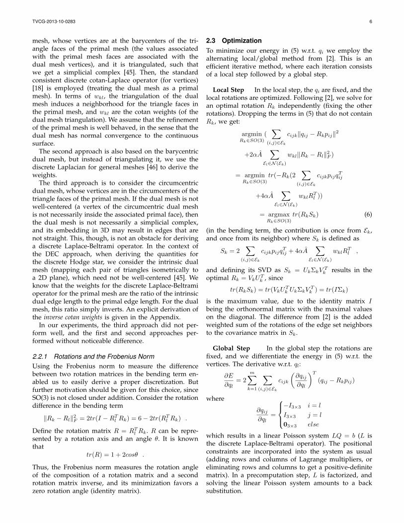
Figure 3: Elephant extrapolation using SR-ARAP: t = −0.25, 0, 0.25, 0.5, 0.75, 1, 1.25 (Source shapes are in yellow,interpolated shapes are in blue, and extrapolated shapes are in pink).
We now consider the maps’ differentials df0k =Q0k(P 0
k )†, df1k = Q1k(P 1
k )† for the surface edge sets(where † stands for pseudoinverse), with P ik, Qik definedas before (but now of dimension 3 × |Ek|, where |Ek|is the number of edges in an edge set Ek), compris-ing of columns of weighted vector edges (e.g. uniformweights). The method in the previous section cannot beused here immediately, since the maps’ differentials arenot unique. When using a 1-ring edge set, the linear sys-tem that determines the map differential, dfikP ik = Qik,is overdetermined, and the surface cannot be uniquelydetermined. Thus, we use a triangle edge set (|Ek| = 3).The linear system that determines its map differential isunderdetermined (three coplanar vectors), and thus theenergy in (9) does not determine a unique shape. There-fore, we regularize the energy by prescribing rotationsdifference (enforcing them in the least-squares sense),such that the surface could be uniquely determined, anddeviation from the interpolated bending is minimized.Note that penalizing the rotation smoothness instead,as in the deformation, is not enough. This is becauseit would only force the rotations to be smooth, while weneed specific information (specific rotation difference) todetermine a desired shape, which does not necessarilyoptimize the rotation smoothness energy. Given the spe-cific rotation difference, the change in the dihedral anglescan be inferred uniquely. For a map fi, we define the ro-tation difference between two edge sets El, Ek as dRilk =RikR
Til , where Rik, Ril are the rotational components of
the respective maps’ differentials of the edge sets (dR0lk
is again the identity). We define the interpolation of therotation difference as dRlk = Slerp(dR0lk, dR1lk; t), andthe linear interpolation of the stretching part Yk as in (8).We solve for an intermediate shape Mt by minimizing(w.r.t. qi, the vertices of Mt)
ESR(M0,M1, t) =
minR1,...,Rm∈SO(3)
m∑k=1
∑(i,j)∈Ek
cijk‖qij −RkYkp0ij‖2
+αA∑
El∈N (Ek)
wkl‖Rk − dRlkRl‖2F , (10)
where p0ij are the edges of the source mesh M0. To reit-erate, the first term in (10) prescribes new interpolatededges in an edge set. The second term prescribes the
interpolated rotation difference between the edge setand its neighbors, which varies between the identitymatrix and the difference between the edge sets andits neighbors in M1, and in essence prescribes an inter-polated dihedral angle. Another perspective is insteadof treating the reference mesh as M0, we interpolatethe reference mesh (between M0 and M1), and then thesecond term is just smoothing the rotations of the mapdifferentials from the interpolated reference mesh (wheresmoothing can be viewed as prescribing zero rotationdifference). Note that unlike the interpolation of edge setrotations with Slerp, interpolating the rotation differencewith Slerp can be regarded as safe, since we expect thedifference to be small for a map between similar shapes.The energy is minimized using the same local/globalmethod described in Section 2.3.
4 RESULTS AND DISCUSSION
Implementation CGAL [47] was used for triangle meshoperations, TetGen [48] for tetrahedral mesh operations,and Eigen [49] for the linear algebra. In our experimentswe did not use interior points when generating thetetrahedral meshes, and we used the surface of thetetrahedral mesh as an input for the surface case. Themodels were scaled to tightly fit inside a unit cubescaled by ten. The source mesh was used as an initialguess for the optimization process. For the SR-ARAPweights in Eq. (5), we experimented with cotan weightsand uniform weights 1 for cijk. For the models withreasonable triangulation quality (where triangles havegood aspect ratio, and their size does not vary much),using 1 for wkl was usually enough to get compellingresults. Otherwise, we used the weights from the firstand second approaches in Section 2.2, which performedsimilarly. In both cases we normalized the weights tosum to one on a neighborhood. The effect of a properdiscretization and the choice of weights is shown inFigures 14, 15, and 16. We used 0.01 for α, which didnot prove to be a sensitive parameter. With the ARAPsurface energy we experimented with the 1-ring edgeset, with and without rim edges, and uniform andcotan weights. With SR-ARAP we experimented withthe three types of surface edge sets. On our models, thechanges in the resulting mesh were imperceptible whenusing different edge sets for the surface energies. For
TVCG-2013-10-0283 9
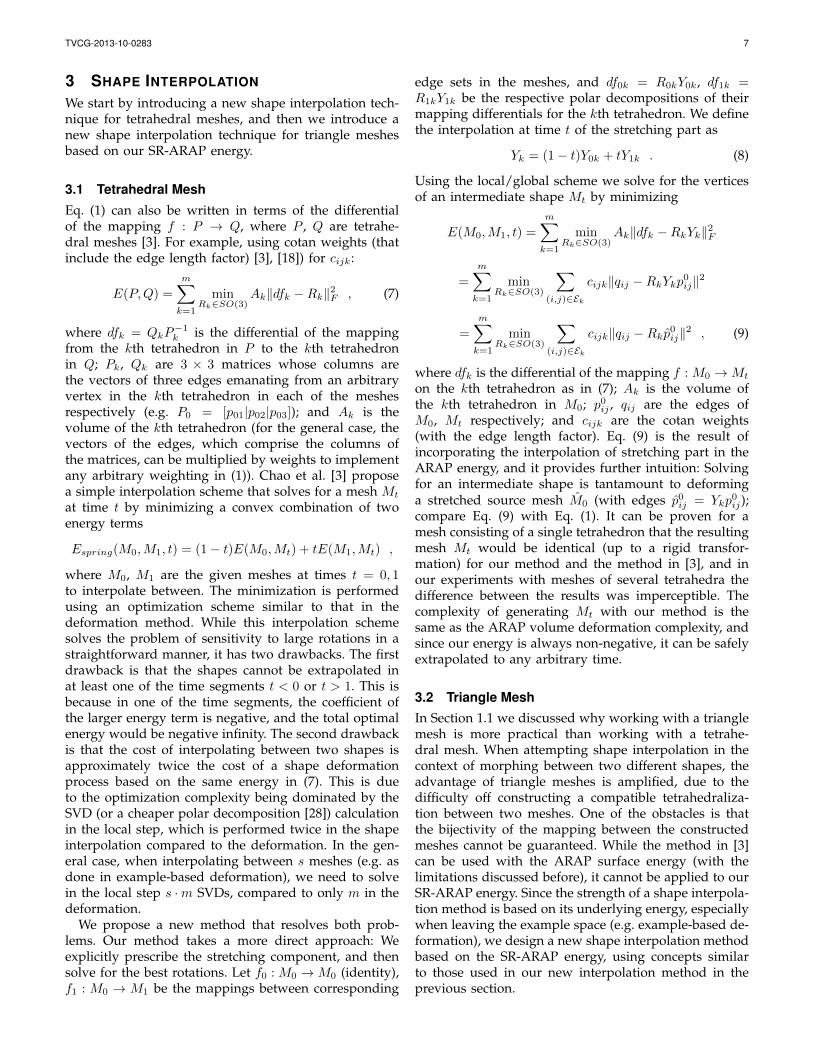
Figure 4: Spiral extrapolation using our formulation forARAP volume: t = −0.25, 0, 0.25, 0.5, 0.75, 1, 1.25,1.5,1.75(Source shapes are in yellow, interpolated shapes are ingreen, and extrapolated shapes are in pink).
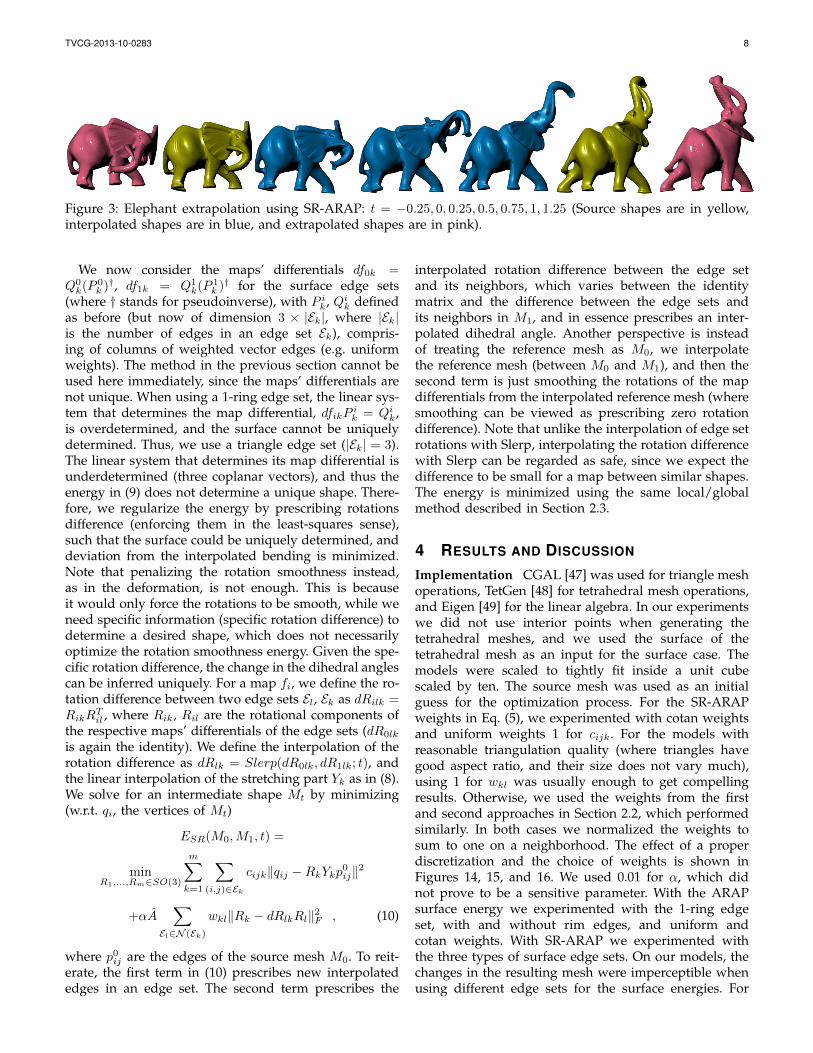
Figure 5: Bar twist extrapolation using our formulationfor ARAP volume: t = −1,−0.5, 0, 0.5, 1,1.5,2 (Sourceshapes are in yellow, interpolated shapes are in green,and extrapolated shapes are in pink).
the ARAP volume (tetrahedral edge sets) we used cotanweights. We stopped the iterative process when themaximum change in the mesh coordinates was below10−3.
Performance It has been noted in [2] that the numberof iterations required to get reasonably close to a mini-mum depends on the condition number of the anchoredLaplacian matrix, which is generally proportional to thenumber of vertices. Moreover, it has been discussedin [1] that the main limitation of the local matching
Model #Ver
tice
s
#Tri
angl
es
#Tet
rahe
dra
Ener
gy
#Ite
rati
ons
T ota
l(s
ec)
Cylinder 4.8 9.6 13 Tri 709 6.9Tet 111 1.7SR 195 2.5
Goblin arm 24 49 88 Tri 166 16Tet 79 7.6SR 285 32
Octopus 149 299 509 Tri 817 368Tet 338 160SR 480 267
Bar twist 6 12 18 Tri 124 3.8Tet 556 10SR 713 16
Elephant 47 95 167 Tri 684 203Tet 741 144SR 988 206
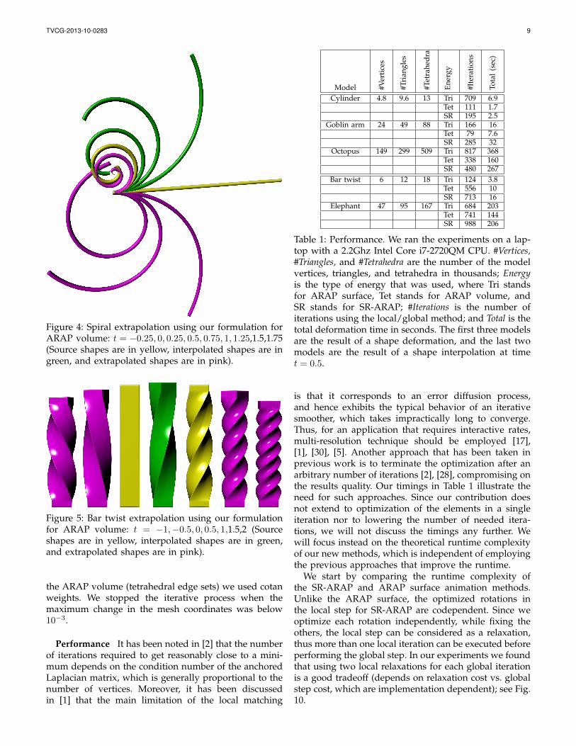
Table 1: Performance. We ran the experiments on a lap-top with a 2.2Ghz Intel Core i7-2720QM CPU. #Vertices,#Triangles, and #Tetrahedra are the number of the modelvertices, triangles, and tetrahedra in thousands; Energyis the type of energy that was used, where Tri standsfor ARAP surface, Tet stands for ARAP volume, andSR stands for SR-ARAP; #Iterations is the number ofiterations using the local/global method; and Total is thetotal deformation time in seconds. The first three modelsare the result of a shape deformation, and the last twomodels are the result of a shape interpolation at timet = 0.5.
is that it corresponds to an error diffusion process,and hence exhibits the typical behavior of an iterativesmoother, which takes impractically long to converge.Thus, for an application that requires interactive rates,multi-resolution technique should be employed [17],[1], [30], [5]. Another approach that has been taken inprevious work is to terminate the optimization after anarbitrary number of iterations [2], [28], compromising onthe results quality. Our timings in Table 1 illustrate theneed for such approaches. Since our contribution doesnot extend to optimization of the elements in a singleiteration nor to lowering the number of needed itera-tions, we will not discuss the timings any further. Wewill focus instead on the theoretical runtime complexityof our new methods, which is independent of employingthe previous approaches that improve the runtime.
We start by comparing the runtime complexity ofthe SR-ARAP and ARAP surface animation methods.Unlike the ARAP surface, the optimized rotations inthe local step for SR-ARAP are codependent. Since weoptimize each rotation independently, while fixing theothers, the local step can be considered as a relaxation,thus more than one local iteration can be executed beforeperforming the global step. In our experiments we foundthat using two local relaxations for each global iterationis a good tradeoff (depends on relaxation cost vs. globalstep cost, which are implementation dependent); see Fig.10.
TVCG-2013-10-0283 10
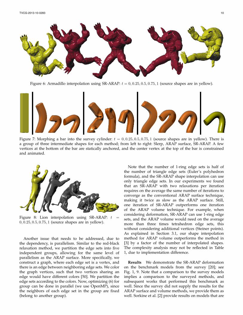
Figure 6: Armadillo interpolation using SR-ARAP: t = 0, 0.25, 0.5, 0.75, 1 (source shapes are in yellow).
Figure 7: Morphing a bar into the survey cylinder: t = 0, 0.25, 0.5, 0.75, 1 (source shapes are in yellow). There isa group of three intermediate shapes for each method; from left to right: Slerp, ARAP surface, SR-ARAP. A fewvertices at the bottom of the bar are statically anchored, and the center vertex at the top of the bar is constrainedand animated.
Figure 8: Lion interpolation using SR-ARAP: t =0, 0.25, 0.5, 0.75, 1 (source shapes are in yellow).
Another issue that needs to be addressed, due tothe dependency, is parallelism. Similar to the red-blackrelaxation method, we partition the edge sets into fiveindependent groups, allowing for the same level ofparallelism as the ARAP surface. More specifically, weconstruct a graph, where each edge set is a vertex, andthere is an edge between neighboring edge sets. We colorthe graph vertices, such that two vertices sharing anedge would have different colors [50]. We partition theedge sets according to the colors. Now, optimizing (6) forgroup can be done in parallel (we use OpenMP), sincethe neighbors of each edge set in the group are fixed(belong to another group).
Note that the number of 1-ring edge sets is half ofthe number of triangle edge sets (Euler’s polyhedronformula), and the SR-ARAP shape interpolation can useonly triangle edge sets. In our experiments we foundthat an SR-ARAP with two relaxations per iterationrequires on the average the same number of iterations toconverge as the conventional ARAP surface technique,making it twice as slow as the ARAP surface. Still,one iteration of SR-ARAP outperforms one iterationof the ARAP volume technique. For example, whenconsidering deformation, SR-ARAP can use 1-ring edgesets, and the ARAP volume would need on the averagemore than three times tetrahedron edge sets, thiswithout considering additional vertices (Steiner points).As explained in Section 3.1, our shape interpolationmethod for ARAP volume outperforms the method in[3] by a factor of the number of interpolated shapes.The complexity analysis may not be reflected in Table1, due to implementation difference.
Results We demonstrate the SR-ARAP deformationon the benchmark models from the survey [20]; seeFig. 1, 9. Note that a comparison to the survey modelsimplies a comparison to the surveyed methods, andsubsequent works that performed this benchmark aswell. Since the survey did not supply the results for theARAP surface and volume methods, we provide them aswell. Sorkine et al. [2] provide results on models that are
TVCG-2013-10-0283 11
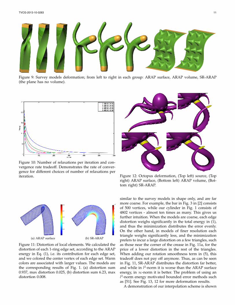
Figure 9: Survey models deformation; from left to right in each group: ARAP surface, ARAP volume, SR-ARAP(the plane has no volume).
Figure 10: Number of relaxations per iteration and con-vergence rate tradeoff. Demonstrates the rate of conver-gence for different choices of number of relaxations periteration.
(a) ARAP surface (b) SR-ARAP
Figure 11: Distortion of local elements. We calculated thedistortion of each 1-ring edge set, according to the ARAPenergy in Eq. (1), i.e. its contribution for each edge set,and we colored the center vertex of each edge set. Warmcolors are associated with larger values. The models arethe corresponding results of Fig. 1. (a) distortion sum0.937, max distortion 0.025, (b) distortion sum 6.23, maxdistortion 0.008.
Figure 12: Octopus deformation, (Top left) source, (Topright) ARAP surface, (Bottom left) ARAP volume, (Bot-tom right) SR-ARAP.
similar to the survey models in shape only, and are farmore coarse. For example, the bar in Fig. 3 in [2] consistsof 500 vertices, while our cylinder in Fig. 1 consists of4802 vertices - almost ten times as many. This gives usfurther intuition. When the models are coarse, each edgedistortion weighs significantly in the total energy in (1),and thus the minimization distributes the error evenly.On the other hand, in models of finer resolution eachtriangle weighs significantly less, and the minimizationprefers to incur a large distortion on a few triangles, suchas those near the corner of the crease in Fig. 11a, for theprice of a lower distortion in the rest of the triangles.When adding our rotation smoothness term in (5), thistradeoff does not pay off anymore. Thus, as can be seenin Fig. 11, SR-ARAP distributes the distortion far better,and while in l2-norm it is worse than the ARAP surfaceenergy, in ∞-norm it is better. The problem of using anl2-norm energy motivated bounded error methods suchas [51]. See Fig. 13, 12 for more deformation results.
A demonstration of our interpolation scheme is shown
TVCG-2013-10-0283 12
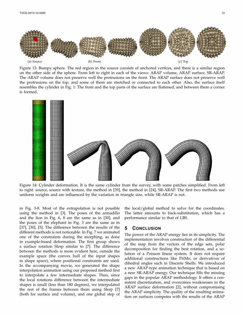
(a) Source (b) Front (c) Top
Figure 13: Bumpy sphere. The red region in the source consists of anchored vertices, and there is a similar regionon the other side of the sphere. From left to right in each of the views: ARAP volume, ARAP surface, SR-ARAP.The ARAP volume does not preserve well the protrusions on the front. The ARAP surface does not preserve wellthe protrusions on the top, and some of them are stretched or connected to each other. Also, the surface itselfresembles the cylinder in Fig. 1: The front and the top parts of the surface are flattened, and between them a corneris formed.
Figure 14: Cylinder deformation. It is the same cylinder from the survey, with some patches simplified. From leftto right: source, source with texture, the method in [39], the method in [24], SR-ARAP. The first two methods useuniform weights and are influenced by the variation in triangle size, while SR-ARAP is not.
in Fig. 3-8. Most of the extrapolation is not possibleusing the method in [3]. The poses of the armadilloand the lion in Fig. 6, 8 are the same as in [30], andthe poses of the elephant in Fig. 3 are the same as in[37], [30], [5]. The difference between the results of thedifferent methods is not noticeable. In Fig. 7 we animatedone of the constraints during the morphing, as donein example-based deformation. The first group showsa surface rotation Slerp similar to [7]. The differencebetween the methods is more evident here, outside theexample space (the convex hull of the input shapesin shape space), where positional constraints are used.In the accompanying movie, we generated the shapeinterpolation animation using our proposed method firstto interpolate a few intermediate shapes. Then, sincethe local rotations difference between the intermediateshapes is small (less than 180 degrees), we interpolatedthe rest of the frames between them using Slerp [7](both for surface and volume), and one global step of
the local/global method to solve for the coordinates.The latter amounts to back-substitution, which has aperformance similar to that of LBS.
5 CONCLUSION
The power of the ARAP energy lies in its simplicity. Theimplementation involves construction of the differentialof the map from the vectors of the edge sets, polardecomposition for finding the best rotation, and a so-lution of a Poisson linear system. It does not requireadditional constructions like PriMo, or derivatives ofdihedral angles such in Discrete Shells. We introduceda new ARAP-type animation technique that is based ona new SR-ARAP energy. Our technique fills the missinggaps in the popular ARAP methodology. It offers a con-sistent discretization, and overcomes weaknesses in theARAP surface deformation [2], without compromisingthe ARAP simplicity. The quality of the resulting anima-tion on surfaces competes with the results of the ARAP

TVCG-2013-10-0283 13
Figure 15: Bar deformation. Some patches on the bar are simplified. On the left are the source mesh and the sourcemesh with a reflection map [19]. The first row of results (from left to right): ARAP surface, the method in [39],the method in [24]. The second row of results: ARAP volume, SR-ARAP with cotan weights for cijk and uniformweights for wkl, SR-ARAP with cotan weights for cijk and the weights from [46] for wkl. The first row of resultsconsists of methods with no proper discretization, which are influenced by the mesh degradation. ARAP volumewas generated without inner points, and thus lacked the freedom to do both bends smoothly. The effect of thedegradation on SR-ARAP, which moves the vertices almost only in-plane, is minimal. The difference between thechoice of weights in the two SR-ARAP results is emphasized by the amount of preservation of the reflection mappattern.
Figure 16: Bar interpolation: t = 0, 0.25, 0.5, 0.75, 1 (source shapes are in yellow). There is a group of threeintermediate shapes for the method in [39] (left) and for SR-ARAP (right). A few vertices at the bottom of thebar are statically anchored, and the center vertex at the top of the bar is constrained and animated. Some patcheson the bar are simplified. This does not affect SR-ARAP, which moves the vertices only in-plane. On the other hand,the method in [39], which uses uniform weights, is influenced by the imbalance in the triangulation.
volume energy. We demonstrated the effectiveness of ourtechnique in the application of shape deformation andshape interpolation. The latter inspired a new ARAPshape interpolation method that is superior to prior artalso based on the ARAP energy. As a future avenue, itwould be interesting to test our new SR-ARAP energyin other applications.
ACKNOWLEDGMENTSWe wish to thank Max Wardetzky, Denis Zorin, andJulian Panetta for insightful discussions. We would also
like to thank Qixing Huang for the results of [39].
REFERENCES
[1] M. Botsch, M. Pauly, M. Gross, and L. Kobbelt, “Primo: coupledprisms for intuitive surface modeling,” in SGP, 2006.
[2] O. Sorkine and M. Alexa, “As-Rigid-As-Possible surface model-ing,” in SGP, 2007, pp. 109–116.
[3] I. Chao, U. Pinkall, P. Sanan, and P. Schröder, “A simple geometricmodel for elastic deformations,” in SIGGRAPH, 2010, pp. 38:1–38:6.
[4] R. W. Sumner, M. Zwicker, C. Gotsman, and J. Popovic, “Mesh-based inverse kinematics,” in SIGGRAPH, 2005.
TVCG-2013-10-0283 14
[5] S. Frohlich and M. Botsch, “Example-driven deformations basedon discrete shells,” CGF, vol. 30, no. 8, pp. 2246–2257, 2011.
[6] V. Kraevoy and A. Sheffer, “Cross-parameterization and compat-ible remeshing of 3D models,” in SIGGRAPH, 2004.
[7] M. Alexa, D. Cohen-Or, and D. Levin, “As-Rigid-As-Possibleshape interpolation,” in SIGGRAPH, 2000, pp. 157–164.
[8] Y. Zhu and S. Gortler, “3D deformation using moving leastsquares.” Harvard Univ.: TR-10-07, Tech. Rep., 2007.
[9] L. Liu, L. Zhang, Y. Xu, C. Gotsman, and S. J. Gortler, “Alocal/global approach to mesh parameterization,” in SGP, 2008,pp. 1495–1504.
[10] Z. Levi and C. Gotsman, “D-Snake: Image registration by As-Similar-As-Possible template deformation,” TVCG, 2013.
[11] D. Sýkora, J. Dingliana, and S. Collins, “As-Rigid-As-Possibleimage registration for hand-drawn cartoon animations,” in NPAR,2009, pp. 25–33.
[12] Q. Huang, M. Wicke, B. Adams, and L. Guibas, “Shape decom-position using modal analysis,” Computer Graphics Forum, vol. 28,no. 2, pp. 407–416, 2009.
[13] P. Borosan, R. Howard, S. Zhang, and A. Nealen, “Hybrid meshediting,” in Eurographics (short papers), 2010, pp. 41–44.
[14] H. Fadaifard and G. Wolberg, “Image warping for retargetinggarments among arbitrary poses,” The Visual Computer, vol. 29,no. 6-8, pp. 525–534, 2013.
[15] H. Yu and J. J. Zhang, “Topology preserved shape deformation,”The Visual Computer, vol. 28, no. 6-8, pp. 849–858, 2012.
[16] Y.-S. Wang, F. Liu, P.-S. Hsu, and T.-Y. Lee, “Spatially andtemporally optimized video stabilization,” IEEE Transactions onVisualization and Computer Graphics, vol. 19, no. 8, pp. 1354–1361,2013.
[17] J. Manson and S. Schaefer, “Hierarchical deformation of locallyrigid meshes.” CGF, pp. 2387–2396, 2011.
[18] M. Meyer, M. Desbrun, P. Schröder, and A. H. Barr, “Discretedifferential-geometry operators for triangulated 2-manifolds,” inProc. VisMath, 2002, pp. 35–57.
[19] E. Grinspun, Y. Gingold, J. Reisman, and D. Zorin, “Computingdiscrete shape operators on general meshes,” Eurographics, vol. 25,no. 3, pp. 547–556, 2006.
[20] M. Botsch and O. Sorkine, “On linear variational surfacedeformation methods,” TVCG, vol. 14, no. 1, pp. 213–230, 2008.
[21] E. Grinspun, A. N. Hirani, M. Desbrun, and P. Schröder, “Discreteshells,” in SCA, 2003, pp. 62–67.
[22] A. Sheffer and V. Kraevoy, “Pyramid coordinates for morphingand deformation,” in 3DPVT, 2004, pp. 68–75.
[23] Y. Lipman, O. Sorkine, D. Levin, and D. Cohen-Or, “Linearrotation-invariant coordinates for meshes,” in SIGGRAPH, 2005,pp. 479–487.
[24] N. Paries, P. Degener, and R. Klein, “Simple and efficient meshediting with consistent local frames,” in Pacific Conference onComputer Graphics and Applications, 2007, pp. 461–464.
[25] J. Huang, X. Shi, X. Liu, K. Zhou, L.-Y. Wei, S.-H. Teng, H. Bao,B. Guo, and H.-Y. Shum, “Subspace gradient domain mesh defor-mation,” in SIGGRAPH, 2006, pp. 1126–1134.
[26] A. Cuno, C. Esperanca, A. Oliveira, and C. P. Roma, “3D As-Rigid-As-Possible deformations using MLS,” in Proc. of ComputerGraphics International Conference, 2007.
[27] M. Zollhöfer, E. Sert, G. Greiner, and J. Süßmuth, “GPU basedARAP deformation using volumetric lattices,” in Eurographics(Short Papers), 2012, pp. 85–88.
[28] A. Jacobson, I. Baran, L. Kavan, J. Popovic, and O. Sorkine, “Fastautomatic skinning transformations,” SIGGRAPH, vol. 30, no. 4,2012.
[29] W. Baxter, P. Barla, and K. Anjyo, “Rigid shape interpolation usingnormal equations,” in NPAR, 2008, pp. 59–64.
[30] T. Winkler, J. Drieseberg, M. Alexa, and K. Hormann, “Multi-scalegeometry interpolation,” CGF, 2010.
[31] Y. Liu, H. Yan, and R. R. Martin, “As-rigid-as-possible surfacemorphing,” J. Comput. Sci. Technol., vol. 26, no. 3, pp. 548–557,2011.
[32] B. Heeren, M. Rumpf, M. Wardetzky, and B. Wirth, “Time-discretegeodesics in the space of shells,” Comp. Graph. Forum, vol. 31,no. 5, pp. 1755–1764, 2012.
[33] J. Huang, Y. Tong, K. Zhou, H. Bao, and M. Desbrun, “Interactiveshape interpolation through controllable dynamic deformation,”TVCG, vol. 17, no. 7, pp. 983–992, 2011.
[34] D. Xu, H. Zhang, Q. Wang, and H. Bao, “Poisson shape inter-polation,” in Symposium on Solid and Physical Modeling, 2005, pp.267–274.
[35] S. Kircher and M. Garland, “Free-form motion processing,” ACMTrans. Graph., vol. 27, no. 2, pp. 12:1–12:13, 2008.
[36] I. Baran, D. Vlasic, E. Grinspun, and J. Popovic, “Semantic defor-mation transfer,” ACM Trans. Graph., vol. 28, 2009.
[37] M. Kilian, N. J. Mitra, and H. Pottmann, “Geometric modeling inshape space,” in SIGGRAPH, 2007.
[38] L. Gao, Y.-K. Lai, Q.-X. Huang, and S.-M. Hu, “A data-drivenapproach to realistic shape morphing,” Comput. Graph. Forum,vol. 32, no. 2, pp. 449–457, 2013.
[39] Q. Huang, B. Adams, M. Wicke, and L. J. Guibas, “Non-rigidregistration under isometric deformations,” in SGP, 2008, pp.1449–1457.
[40] G. Friesecke, R. D. James, and S. Müller, “A theorem on geometricrigidity and the derivation of nonlinear plate theory from three-dimensional elasticity,” Comm. Pure Appl. Math., vol. 55, no. 11,pp. 1461–1506, 2002.
[41] U. Pinkall and K. Polthier, “Computing discrete minimal surfacesand their conjugates,” Experimental Mathematics, vol. 2, no. 1, pp.15–36, 1993.
[42] K. Crane, F. de Goes, M. Desbrun, and P. Schröder, “Digital ge-ometry processing with discrete exterior calculus,” in SIGGRAPHCourses, 2013, pp. 7:1–7:126.
[43] B. Lévy and H. R. Zhang, “Spectral mesh processing,” in SIG-GRAPH Courses, 2010, pp. 8:1–8:312.
[44] M. Wardetzky, S. Mathur, F. Kälberer, and E. Grinspun, “DiscreteLaplace operators: no free lunch,” in SGP, 2007, pp. 33–37.
[45] A. N. Hirani, “Discrete exterior calculus,” Ph.D. dissertation,California Institute of Technology, 2003.
[46] M. Alexa and M. Wardetzky, “Discrete laplacians on generalpolygonal meshes,” in SIGGRAPH, 2011, pp. 102:1–102:10.
[47] “CGAL, Computational Geometry Algorithms Library,”http://www.cgal.org.
[48] H. Si, “TetGen. a quality tetrahedral mesh gener-ator and three-dimensional delaunay triangulator.”URL:http://tetgen.berlios.de, 2007.
[49] G. Guennebaud, B. Jacob et al., “Eigen v3,”http://eigen.tuxfamily.org, 2010.
[50] N. Robertson, D. P. Sanders, P. Seymour, and R. Thomas, “Effi-ciently four-coloring planar graphs,” in Symposium on Theory ofComputing, 1996, pp. 571–575.
[51] Y. Lipman, “Bounded distortion mapping spaces for triangularmeshes,” TOG, vol. 31, no. 4, pp. 108:1–108:13, 2012.
[52] M. Desbrun, A. N. Hirani, M. Leok, and J. E. Marsden, “Discreteexterior calculus,” arXiv:math/0508341v2, 2005.
Zohar Levi received his PhD in computer sci-ence from the Technion, Israel, in 2013. His re-search interests include computer graphics andgeometry processing.
Craig Gotsman received a PhD in computer sci-ence from the Hebrew University of Jerusalem.Since 1991, he has been on the Faculty of Com-puter Science at the Technion at Haifa, Israel,where he co-founded the Center for Graphicsand Geometric Computing (CGGC). His mainresearch interests are computer graphics, geom-etry processing and geometric modeling.
TVCG-2013-10-0283 15
APPENDIX: INVERSE COTAN WEIGHTS
Following Section 6.4 in [45] (a similar derivation isgiven in Section 9 in [52], and in Section 6.3 in [42]), wedevelop the explicit formula for the inverse cotan-Laplace.We compute ∆R on a dual vertex ?σ2 (corresponding tothe primal triangle face σ2). We have that
< ∆R, ?σ2 > = < δdR, ?σ2 >
= − < ?d ? dR, ?σ2 > .
Using the definition of the discrete Hodge star, followedby the discrete Stokes’ theorem (and the definition forthe volume of a vertex | ? σ2| = 1), we get
= −| ? σ2|
|σ2|< d ? dR, σ2 >
= − 1
|σ2|< ?dR, ∂(σ2) > .
By the definition of the boundary operator
= − 1
|σ2|< ?dR,
∑σ1∈σ2
σ1 >
= − 1
|σ2|∑σ1∈σ2
< ?dR, σ1 > ,
where σ1 is one of the three edges in σ2. Using thedefinition of the discrete Hodge star:
= − 1
|σ2|∑σ1∈σ2
|σ1|| ? σ1|
< dR, ?σ1 >
= − 1
|σ2|∑σ1∈σ2
|σ1|| ? σ1|
(R(vj)−R(vi)) ,
where vi, vj are two dual vertices, which are the endpoints of a dual edge ?σ1. To remind, |σ2| is the area ofa primal triangle face, and
| ? σ1||σ1|
=1
2(cotα+ cotβ) ,
where α, β are two opposing angles to a primal edgeσ1. One pitfall that should be noted is that a dual edgecannot have zero length.