Embed Size (px)
Citation preview
P. C. Electronics 2522 Paxson Lane Arcadia CA 91007-8537 USA ©2007Tom (W6ORG) & Mary Ann (WB6YSS) Tel: (626) 447-4565 m-th 8am-5pm pst (UTC - 8)
Web site: www.hamtv.com Email: [email protected]
The TVC-12S is a ready to go ATV downconverter designed to mix the 5 standard ATV frequencies in the 1240-1300MHz amateur band down to TV channel 7, or 8 with 15 to 20 dB gain. The preamp stage uses a HJ-FET with a <.4 dB noisefigure. A TVCX-12S board is mounted in a shielded enclosure ready to go with external +12 Vdc or 120 Vac 60 Hz powersupply adapter.
TVC-12S 1240-1300 MHz ATV DOWNCONVERTER
TVCX-S BoardRF AGC (optional): designed for use with VRC-45 receiver board. For manualRF gain an external 10K pot to vary from 0 to 8 Vdc can be added to reducestrong signals as may be found during demos or public service operations. 8Vat the AGC solder pad is the highest gain and the preamp bias pot on the boardis set for that. If the no signal AGC is less such as when connected to the VRC-45 receiver RF AGC (6V nominal) the preamp bias is reset for max gain on aweak signal. C1 can also be fine peaked for best picture on a weak signal.
LED: Run leads from the LED solder pads to a panel mount LED to indicatepower on. Square pad is the + side.or anode.
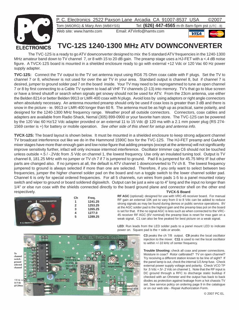
TVCX-12S: The board layout is shown below. It must be mounted in a shielded enclosure to keep strong adjacent channelTV broadcast interference out like we do in the Hammond 1590C box for the TVC-12S. The HJ-FET preamp and GaAsfetmixer stages have more than enough gain and low noise figure that adding preamps (except at the antenna) will not significantlyimprove sensitivity further, infact will only increase intermod interference. Oscillator trimmer cap C6 should not be touchedunless outside +.5 / -.2Vdc from .5 Vdc on channel 1, the lowest frequency. Use only an insulated tuning tool. Output is TVchannel 8, 181.25 MHz with no jumper or TV ch 7 if 7 is jumpered to ground. Pad 8 is jumpered for 45.75 MHz IF but otherparts are changed also. If no jumpers at all, the default is ATV channel 1 downconverted to TV ch 8. The lowest frequencyjumpered to ground is always selected if more than one are selected. Therefore, if you only want to select between twofrequencies, jumper the higher channel solder pad on the board and run a toggle switch to the lower channel solder pad.Channel 6 is only for special ordered frequencies. For all 5 channels, run wires from pads 1-5 to a panel mounted rotaryswitch and wiper to ground or board soldered digiswitch. Output can be just a wire up to 4” long and the input no longer than1/4” or else run coax with the shields connected directly to the board ground plane and connector shell on the other endrespectively.
TVC-12S: Connect the TV output to the TV set antenna input using RG6 75 Ohm coax cable with F plugs. Set the TV tochannel 7 or 8, whichever is not used for over the air TV in your area. Standard output is channel 8, but if channel 7 isdesired, jumper to ground solder pad 7 on the board inside. Your TV may need to be reprogammed to tune an open channel7 or 8 by first connecting to a Cable TV system to load all VHF TV channels (2-13) into memory. TV’s that go to blue screenor have a timed shutoff or search when signals get snowy should not be used for ATV. From the 23cm antenna, use eitherthe Belden 8214 or better Belden 9913 or LMR-400 coax with N plugs. Avoid loss by using adaptors or right angle connectorswhen absolutely necessary. An antenna mounted preamp should only be used if coax loss is greater than 3 dB and there issnow in the picture - ie. 9913 or LMR-400 longer than 60 ft. The antenna must be as high up as practical, same polarity, anddesigned for the 1240-1300 MHz frequency range. Weather proof all outside connectors. Connectors, coax cables andadapters are available from Radio Shack, Nemal (305) 899-0900 or your favorite ham store. The TVC-12S can be poweredby the 120 Vac 60 Hz/12 Vdc adapter provided or an external 11 to 15 Vdc @ 120 ma with a 2.1 mm power plug (RS 274-1569 center is +) for battery or mobile operation. See other side of this sheet for setup and antenna info.
ToLED
12
ch7
345
45IF
+11 to14 Vdc@120ma
Tochannelswitch -groundselectedchannel
Output
Input
C6VCO
Local OscVCO C6 is setto .5 Vdc onchannel 1 atTP
AGC jumpered to+8 if external +8 to0V not used.
C1 inputtuning
C2 preampoutput tuning
Ch Freq. 1 1241.25 2 1253.25 3 1265.25 4 1277.0 5 1289.25
C3 peaks the ch 7/8 output. C9 peaks the local oscillatorinjection to the mixer. C11 is used to net the local oscillatorto within +/-10 kHz of center frequency.
Trouble Shooting: check all coax and power connections.Moisture in coax? Rotor calibrated? TV on open channel?Try receiving a different station known to be line of sight? Ifthe panel lamp is out, check the internal 1/2 Amp fuse. Checkexternal power supply voltage and polarity. Check VCO TPfor .5 Vdc +.5/-.2 Vdc on channel 1. Note that the RF input isDC ground through a RFC to discharge static buildup ifchecked with an Ohmeter and the output has back to backdiodes as protection against leakage from a hot chassis TVset. See service policy on ordering page 9 in the catalogueor on our web site - Repair Authorization Form.
© 2007 PC EL
C3
C9
ANTENNA SYSTEMSThe antenna system is the most important part of your
ATV system. The antenna must be the same polarity as thetransmitting antenna and line of sight between them if at allpossible. Trees, foliage, houses, etc. greatly absorb UHFenergy. Compared to FM voice systems with the same power,antenna, etc. just the system bandwidth going from 15 KHzto 3 MHz in the receiver will decrease your sensitivity 23 dB.With this bandwidth the noise power floor is around .8 µV.So you can see quality coax and high gain antennas up ashigh as possible are necessary to make up this differencecompared to the DX you are used to with FM simplex.
Find out from local hams which polarity is in use.Performance in the 23 cm band is the same for horizontal orvertical, but cross polarization can cost you up to 20 dB. Areaswhich have had most hams come to ATV from 1296 MHzweak signal CW or SSB will tend to be horizontal, and thosethat were on UHF FM or more into public service and mobilewill be vertical. Most repeaters will be vertical due to thelower cost and ease of buying omnidirectional gain antennas.
Antenna separation should be at least 7 ft, in line, drivenelement end to end spacing with 70 or 33 cm antennas forduplex ATV or crossband repeater work.
Antennas for ATV work must also have broad bandwidthas well as gain. Most high gain Yagi types have only 1%bandwidth, or 12 MHz at 23 cm. This will give less gain andhigher VSWR to the most important color and soundsubcarriers assuming that the antenna was cut for the exactvideo carrier frequency in the first place. The best truereference for antenna gains and performance is the resultsof the various VHF/UHF Conferences antenna measuringcontests held annually and publicized in the ham magazines.Advertising claims have become mostly wishful thinking andsales hype.
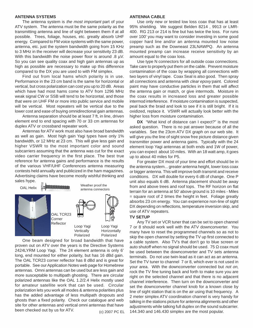
One beam designed for broad bandwidth that haveproven out on ATV over the years is the Directive Systems2424LYRM Loop Yagi. The 24 element antenna is only 6’long, end mounted for either polarity, but has 16 dBd gain.The OAL TCR23 corner reflector has 8 dBd and is great forportable. See our Application Notes web page for Homebrewantennas. Omni antennas can be used but are less gain andmore susceptable to multipath ghosting. There are circularpolarized antennas like the OAL 1.2/2.4 Helix mostly usedfor amateur satellite work that can be used. Circularpolarization lets you work all modes & antenna polarities plushas the added advantage of less multipath dropouts andghosts than a fixed polarity. Check our catalogue and website for other antennas and vertical omni antennas that havebeen checked out by us for ATV.
ANTENNA CABLEUse only new or tested low loss coax that has at least
95% shielding. We suggest Belden 8214 , 9913 or LMR-400. RG 213 or 214 is fine but has twice the loss. For runsover 100' you may want to consider investing in some goodcopper hard line and/or an antenna mounted low noisepreamp such as the Downeast 23LNAWPQ. An antennamounted preamp can increase receive sensitivity by anamount equal to the coax loss.
Use type N connectors for all outside coax connections.Take care to properly put them on the cable. Prevent moisturecontamination of the coax by wrapping all connections withtwo layers of vinyl tape. Coax Seal is also good. Then sprayall connections and antenna with clear epoxy paint. Coloredpaint may have conductive particles in them that will affectthe antenna gain or match, or give intermods. Moisture inthe coax results in increased loss and greater possibleintermod interference. If moisture contamination is suspected,peal back the braid and look to see if it is still bright. If it isoxidized, replace it. VSWR will actually look better with thehigher loss from moisture contamination.
DX “What kind of distance can I expect?” is the mostasked question. There is no pat answer because of all thevariables. See the 23cm ATV DX graph on our web site. Itwill give you the line of sight snow free picture distance giventransmitter power and antenna gains. Typically with the 24element loop Yagi antennas at both ends and 1W of power,you can expect about 10 miles. With an 18 watt amp, it goesup to about 40 miles for P5.
For greater DX most of your time and effort should be inthe antenna system... greater antenna height, lower loss coaxor bigger antenna. This will improve both transmit and receiveconditions. DX will double for every 6 dB of change. One Punit also equals 6 dB. Antenna placement should be awayfrom and above trees and roof tops. The RF horizon on flatterrain for an antenna at 50' above ground is 10 miles - Miles= square root of 2 times the height in feet. Foliage greatlyabsorbs 23 cm energy. You can experience non-line of sightDX depending on reflections, temperature inversion skip, anduse of ATV repeaters.TV SETUP
Any TV set or VCR tuner that can be set to open channel7 or 8 should work well with the ATV downconverter. Youmany have to reset the programmed channels so as not toskip the open channel by setting the TV up first connected toa cable system. Also TV’s that don’t go to blue screen orauto shutoff when no signal should be used. 75 Ω coax mustbe used between the downconverter and TV sets antennaterminals. Do not use twin-lead as it can act as an antenna.Set the TV tuner to channel 7 or 8, which ever is not used inyour area. With the downconverter connected but not on,rock the TV fine tuning back and forth to make sure you areright on the selected channel and that there is no adjacentchannel interference. Then turn on the downconverter andset the downconverter channel knob for a known close byline of sight station that is on the air using that frequency. A2 meter simplex ATV coordination channel is very handy fortalking in the stations picture for antenna alignments and otheradjustments while talking full duplex on the sound subcarrier.144.340 and 146.430 simplex are the most popular.
Weather proof theantenna connectors
(c) 2007 PC EL
Loop YagiHorizontallyPolarized
Loop YagiVerticallyPolarized
OAL Helix
OAL TCR23CornerReflector