Embed Size (px)
Citation preview

PROJECT
FILES
Understandingand Maintaining
Project Files
Introduction to
with
TNTmips®
TNTeditTNTview

page 2
Understanding and Maintaining Project Files
Before Getting StartedThe Project File is a key component of the TNT products. Project Files can containany number of objects of a variety of types (for example, raster, vector, CAD, TIN,database, text...) up to the 16 TB size limit. To your operating system, thiscollection of data appears as a single file. TNTmips, TNTedit, and TNTviewprovide the tools for you to get information about each object in a Project File andto manipulate the files in non-analytical ways, such as copying or deleting filesor objects and editing object names and descriptions, in addition to theiranalytical capabilities. File and object access permissions are set in the FileManager process also.
Prerequisite Skills This booklet assumes you have completed the exercises inthe Displaying Geospatial Data and TNT Product Concepts tutorials. Theexercises in those booklets introduce essential skills and basic techniques, whichare not covered again here. These prerequisites will help to provide a context andthe terminology to help you better understand the concepts in this booklet.
Sample Data For the most part, this booklet does not use exercises with specificsample data to develop the topics presented. However, there is some specific dataprovided, and you should make a read-write copy of the PROJFILE folder in the DATA
directory of your TNT products on your hard drive for use with this booklet. Ifyou do not have access to a TNT products CD, download the data from MicroIm-ages’ web site.
More Documentation This booklet is intended only as an introduction tomanaging Project Files. Details of the processes discussed can be found in avariety of tutorial booklets, color plates, and Quick Guides, which are all availablefrom MicroImages’ web site (go to http://www.microimages.com/search to quicklysearch all available materials, or you can narrow your search to include onlytutorials, Technical Guides, or Quick Guides).
TNTmips Pro, TNTmips Basic, and TNTmips Free TNTmips comes in threeversions: TNTmips Pro, TNTmips Basic, and TNTmips Free. If you did notpurchase the professional version (which requires a software license key), you areusing TNTmips Free or TNTmips Basic, which limit the size of your projectmaterials. All exercises in this booklet can be completed in TNTmips Free usingthe sample geodata provided.
You can print or read this booklet in color from MicroImages’ web site. The website is also your source of the newest tutorial booklets on other topics. You candownload an installation guide, sample data, and the latest version ofTNTmips Free.
http://www.microimages.com
Merri P. Skrdla, Ph.D., 28 May 2013© MicroImages, Inc. 2005–2013

page 3
Understanding and Maintaining Project Files
Introduction to Project Files
Page 4 introduces the toolsand functions available inthe File Manager. Page 5presents the different objectand subobject types in theTNT products. Pages 6–10provide more detail on thetools and functions of theFile Manager. Page 11introduces Access ControlLists. Page 12 presentsinformation on automaticlink files (*.rlk). Pages 13–16 discuss Project Filevalidity issues and page 17discusses the RecoverProject File process.
A TNT Project File is a unique container for spatialgeodata in raster, vector, shape, CAD, LiDAR, TIN,database, and region form. Each of these objecttypes can have a variety of subobjects, such asgeoreference (all except database), color map(rasters), style (vector, CAD, TIN, shape, LiDAR,and database), pyramid (raster), and index (da-tabase) subobjects. Databases can also be sub-objects of vector, shape, CAD, TIN, LiDAR andsome types of raster objects. Style objects canalso be main level objects. Project Files mayalso contain non-spatial objects, such as savedgroups and layouts as well as text and scriptobjects. For a basic discussion of objects and theseobject types, refer to the TNT Product Conceptstutorial booklet.
Most Project Files have an RVC extension. Projectfiles created for direct, transparent use of files inexternal formats, such as shape and JP2 have an RLK
extension. These Project Files contain the subob-jects you create for the external file, such as georef-erence, database, and pyramid subobjects. ProjectFiles that link to tilesets have an RVC extension.
Project Files can have an internal folder structure tobetter organize the many objects within. Althoughthe Project File was designed to keep all materials fora project in a single file, you can organize yourproject materials however you like. Regardless ofthe number of objects, a Project File appears as asingle file to your operating system. Most ProjectFile management activities are done with the FileManager (Tools/File Manager) but some features areavailable wherever you can select objects for use.File contents can also be viewed during any selec-tion procedure but will be filtered if your viewingoptions are set to selectable files only. To see all thecontents of a Project File during object selection, setthe Objects of Type or Files option in the SelectObjects window to All.
Note: The TNT productsare supported on Windows(XP, Vista, and 7) and Mac(PPC and Intel), which uti-lize both low-high and high-low byte orders. The TNTproducts transparentlyhandle byte order issuesand you can use the sameProject Files on both typesof platforms.
page 4
Understanding and Maintaining Project Files
EditAccess
Control List
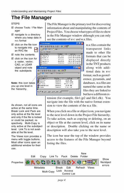
The File Manager is the primary tool for discoveringinformation about and manipulating the contents ofProject Files. You choose what types of files to showin the File Manager window although you can onlysee the contents of RVC and RLK files.
RLK files contain thetransparent linksmade to other fileformats that can bedisplayed directlyin the TNT productsalong with addi-tional data in RVC
format, such as georef-erence, pyramids, anddatabases. RLK files arenamed the same as thefiles they are linked tobut have a different ex-
tension (for example, file1.jp2 and file1.rlk). Younavigate into the file with the native format exten-sion to view the contents of the RLK file.
When you click on a file or object icon, you navigateto the next level down in the Project File hierarchy.To take action, such as copying or deleting, on anobject or file at the current level, click on its nameor description. Double clicking on the name ordescription will also take you to the next level.
The icon bar near the top of the window providesaccess to the features of the File Manager beyondlisting the files.
The File ManagerSTEPS
choose Tools / File Man-ager
navigate to a directorywhere you keep data inRVC format
click on the file iconto navigate intoan RVC file
note the contents
click on the icon fora raster, vector,CAD, or LiDARobject and notethe subobjects
Metadata Break Refresh Views
Multi-Copy
Edit Copy Link To Pack Delete Folder
As shown, not all icons areactive at the same time.Break Lock and Pack areonly active at the file leveland only if the file is lockedor could be packed, re-spectively. Multi-Copy isonly active at the subobjectlevel. Link To is not avail-able at the file level.
The Views icon provides amenu with toggle buttons.Most other icons open anadditional window for theiruse.
New
Showfile/object
errorsProperties
Lock
Note: this icon takesyou up one level inthe hierarchy.

page 5
Understanding and Maintaining Project Files
Know Your Object Types
elementsearch tree
Project File
databaseparameters
TNTmips uses icons to represent each of its objecttypes. Many of these icons are used in other pro-cesses, such as the Display process and object selec-tion, but many are encountered only in the FileManager because they are found at the subobjectlevel or even as subobjects of subobjects. For ex-ample, a vector object is a main level object that mayhave a number of subobjects, one of which is apolygon database, which has table subobjects, andeach of those may have database parameters, index,and constraints subobjects. When you are viewingthese latter subobjects, you have navigated fourlevels down in the Project File.
This organization keeps all the components associ-ated with an individual object as a single unit. Whenan object is selected for any process, all of its subob-jects and their subobjects are automatically selectedor available without the constraint of having thesame name.
STEPS
continue browsingthrough your files or thesample data
hyperspectralsensorinformation
raster
vector
shape
CAD
TIN
region
hyperspectral
database
legend
spectrallibrary
SML
frequencyfilterinformation
layout
group
template
spatialsearch tree
databasetable
databaseform
thumbnailsfolder
databaseconstraints
georeference
histogram
color map
contrast table
metadata
HyperIndex
displayparameters
style
Note: when you click on anobject’s icon in the FileManager, you navigatedown one level. To selectan object for some opera-tion, click on its name ordescription.
theme mapdefinition
Note: you do not need tomemorize these icons; aToolTip identifying the iconappears when you pausethe mouse over an icon.
LiDAR
page 6
Understanding and Maintaining Project Files
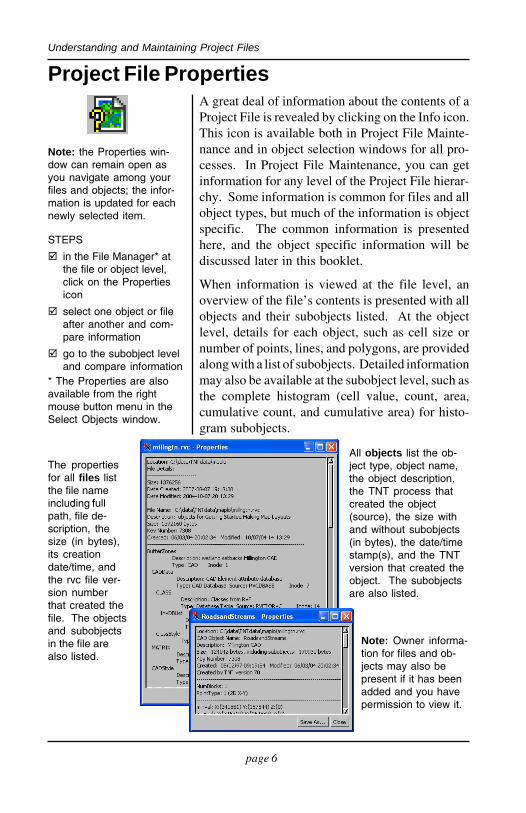
A great deal of information about the contents of aProject File is revealed by clicking on the Info icon.This icon is available both in Project File Mainte-nance and in object selection windows for all pro-cesses. In Project File Maintenance, you can getinformation for any level of the Project File hierar-chy. Some information is common for files and allobject types, but much of the information is objectspecific. The common information is presentedhere, and the object specific information will bediscussed later in this booklet.
When information is viewed at the file level, anoverview of the file’s contents is presented with allobjects and their subobjects listed. At the objectlevel, details for each object, such as cell size ornumber of points, lines, and polygons, are providedalong with a list of subobjects. Detailed informationmay also be available at the subobject level, such asthe complete histogram (cell value, count, area,cumulative count, and cumulative area) for histo-gram subobjects.
Project File Properties
STEPS
in the File Manager* atthe file or object level,click on the Propertiesicon
select one object or fileafter another and com-pare information
go to the subobject leveland compare information
The propertiesfor all files listthe file nameincluding fullpath, file de-scription, thesize (in bytes),its creationdate/time, andthe rvc file ver-sion numberthat created thefile. The objectsand subobjectsin the file arealso listed.
All objects list the ob-ject type, object name,the object description,the TNT process thatcreated the object(source), the size withand without subobjects(in bytes), the date/timestamp(s), and the TNTversion that created theobject. The subobjectsare also listed.
Note: Owner informa-tion for files and ob-jects may also bepresent if it has beenadded and you havepermission to view it.
Note: the Properties win-dow can remain open asyou navigate among yourfiles and objects; the infor-mation is updated for eachnewly selected item.
* The Properties are alsoavailable from the rightmouse button menu in theSelect Objects window.
page 7
Understanding and Maintaining Project Files
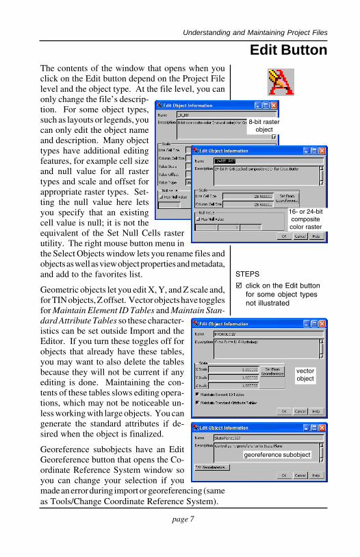
Edit ButtonThe contents of the window that opens when youclick on the Edit button depend on the Project Filelevel and the object type. At the file level, you canonly change the file’s descrip-tion. For some object types,such as layouts or legends, youcan only edit the object nameand description. Many objecttypes have additional editingfeatures, for example cell sizeand null value for all rastertypes and scale and offset forappropriate raster types. Set-ting the null value here letsyou specify that an existingcell value is null; it is not theequivalent of the Set Null Cells rasterutility. The right mouse button menu inthe Select Objects window lets you rename files andobjects as well as view object properties and metadata,and add to the favorites list.
Geometric objects let you edit X, Y, and Z scale and,for TIN objects, Z offset. Vector objects have togglesfor Maintain Element ID Tables and Maintain Stan-dard Attribute Tables so these character-istics can be set outside Import and theEditor. If you turn these toggles off forobjects that already have these tables,you may want to also delete the tablesbecause they will not be current if anyediting is done. Maintaining the con-tents of these tables slows editing opera-tions, which may not be noticeable un-less working with large objects. You cangenerate the standard attributes if de-sired when the object is finalized.
Georeference subobjects have an EditGeoreference button that opens the Co-ordinate Reference System window soyou can change your selection if youmade an error during import or georeferencing (sameas Tools/Change Coordinate Reference System).
STEPS
click on the Edit buttonfor some object typesnot illustrated
8-bit rasterobject
16- or 24-bitcompositecolor raster
vectorobject
georeference subobject

page 8
Understanding and Maintaining Project Files
Metadata is information about an object. It may beas simple as the date it was created but generallymetadata provides considerably more information.The Federal Geographic Data Committee (FGDC)has developed a Content Standard for Digital Geo-spatial Metadata, which is presented in a 90 pagedocument available from www.fgdc.gov/metadata/geospatial-metadata-standards. These standards werecompiled to get all federal agencies to use the samewords for the same data elements. The FGDC encour-ages the use of their standard by the private sectorand all levels of government. Any data you down-load from a federal government agency collectedafter 1994 should have metadata in this form.
The TNT products store metadata as a subobject ofthe object the metadata refers to. You can also createmetadata for a Project File. This metadata is storedas a main level object in the file. You can enter yourown metadata or insert the contents of a text file orobject as metadata. Thus, when you acquire datafiles that include metadata, you can store that infor-mation as a subobject if you click on the Metadatabutton in the File Manager or, in any Object Selec-tion window, choose Edit/Insert File and select themetadata. You can then edit or add to this metadataif desired.
Metadata can also be attached usingT o o l s / M i s c e l l a n e o u s / A t t a c hMetadata, which allows you to attachthe same metadata file to multiple ob-jects. It also lets you attach the metadataas a link so you can maintain a singlemaster metadata file and have it up-dated for viewing with all objects towhich it is linked. TIGER/Line® files,which are prepared by the US CensusBureau, have associated metadata start-ing in 2003.
STEPS
in the File Manager, clickon the Metadata icon
enter text or select a fileto provide metadata forthe object/file
Metadata
The TIGER/Line files areextracts of selected geo-graphic and cartographicinformation from the Cen-sus Bureau’s TIGER® (To-pologically Integrated Geo-graphic Encoding and Ref-erencing) database. Thewindow below shows asample of the metadata youget with 2004 TIGER/Linefiles. Metadata for thenewer TIGER/Lineshapefiles is in XML format.
page 9
Understanding and Maintaining Project Files
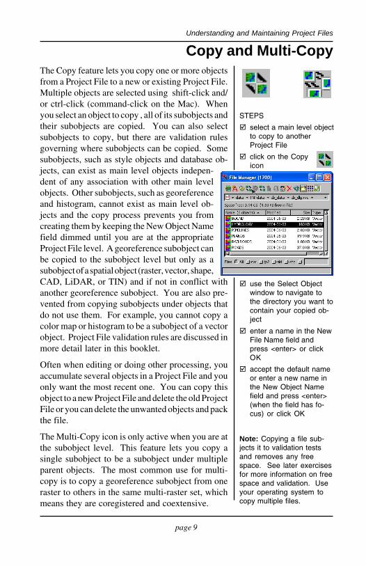
Copy and Multi-CopyThe Copy feature lets you copy one or more objectsfrom a Project File to a new or existing Project File.Multiple objects are selected using shift-click and/or ctrl-click (command-click on the Mac). Whenyou select an object to copy , all of its subobjects andtheir subobjects are copied. You can also selectsubobjects to copy, but there are validation rulesgoverning where subobjects can be copied. Somesubobjects, such as style objects and database ob-jects, can exist as main level objects indepen-dent of any association with other main levelobjects. Other subobjects, such as georeferenceand histogram, cannot exist as main level ob-jects and the copy process prevents you fromcreating them by keeping the New Object Namefield dimmed until you are at the appropriateProject File level. A georeference subobject canbe copied to the subobject level but only as asubobject of a spatial object (raster, vector, shape,CAD, LiDAR, or TIN) and if not in conflict withanother georeference subobject. You are also pre-vented from copying subobjects under objects thatdo not use them. For example, you cannot copy acolor map or histogram to be a subobject of a vectorobject. Project File validation rules are discussed inmore detail later in this booklet.
Often when editing or doing other processing, youaccumulate several objects in a Project File and youonly want the most recent one. You can copy thisobject to a new Project File and delete the old ProjectFile or you can delete the unwanted objects and packthe file.
The Multi-Copy icon is only active when you are atthe subobject level. This feature lets you copy asingle subobject to be a subobject under multipleparent objects. The most common use for multi-copy is to copy a georeference subobject from oneraster to others in the same multi-raster set, whichmeans they are coregistered and coextensive.
STEPS
select a main level objectto copy to anotherProject File
click on the Copyicon
use the Select Objectwindow to navigate tothe directory you want tocontain your copied ob-ject
enter a name in the NewFile Name field andpress <enter> or clickOK
accept the default nameor enter a new name inthe New Object Namefield and press <enter>(when the field has fo-cus) or click OK
Note: Copying a file sub-jects it to validation testsand removes any freespace. See later exercisesfor more information on freespace and validation. Useyour operating system tocopy multiple files.
page 10
Understanding and Maintaining Project Files
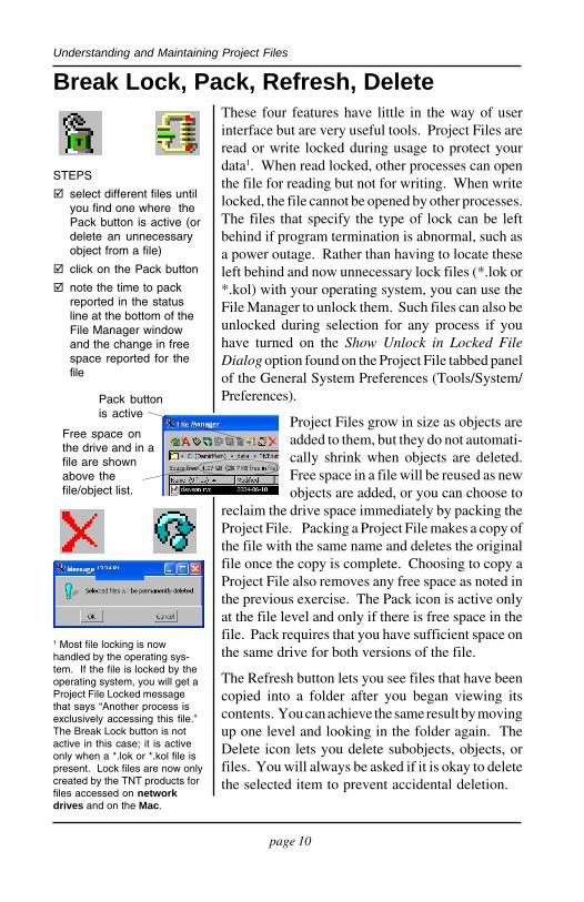
Break Lock, Pack, Refresh, DeleteThese four features have little in the way of userinterface but are very useful tools. Project Files areread or write locked during usage to protect yourdata1. When read locked, other processes can openthe file for reading but not for writing. When writelocked, the file cannot be opened by other processes.The files that specify the type of lock can be leftbehind if program termination is abnormal, such asa power outage. Rather than having to locate theseleft behind and now unnecessary lock files (*.lok or*.kol) with your operating system, you can use theFile Manager to unlock them. Such files can also beunlocked during selection for any process if youhave turned on the Show Unlock in Locked FileDialog option found on the Project File tabbed panelof the General System Preferences (Tools/System/Preferences).
Project Files grow in size as objects areadded to them, but they do not automati-cally shrink when objects are deleted.Free space in a file will be reused as newobjects are added, or you can choose to
reclaim the drive space immediately by packing theProject File. Packing a Project File makes a copy ofthe file with the same name and deletes the originalfile once the copy is complete. Choosing to copy aProject File also removes any free space as noted inthe previous exercise. The Pack icon is active onlyat the file level and only if there is free space in thefile. Pack requires that you have sufficient space onthe same drive for both versions of the file.
The Refresh button lets you see files that have beencopied into a folder after you began viewing itscontents. You can achieve the same result by movingup one level and looking in the folder again. TheDelete icon lets you delete subobjects, objects, orfiles. You will always be asked if it is okay to deletethe selected item to prevent accidental deletion.
STEPS
select different files untilyou find one where thePack button is active (ordelete an unnecessaryobject from a file)
click on the Pack button
note the time to packreported in the statusline at the bottom of theFile Manager windowand the change in freespace reported for thefile
Free space onthe drive and in afile are shownabove thefile/object list.
Pack buttonis active
1 Most file locking is nowhandled by the operating sys-tem. If the file is locked by theoperating system, you will get aProject File Locked messagethat says “Another process isexclusively accessing this file.”The Break Lock button is notactive in this case; it is activeonly when a *.lok or *.kol file ispresent. Lock files are now onlycreated by the TNT products forfiles accessed on networkdrives and on the Mac.

page 11
Understanding and Maintaining Project Files
Access Control ListsAn access control list determines who can view andmanipulate the contents of a file, object, or subob-ject. You can even control who has access to indi-vidual database tables and database fields. Thus, aspecific user may be unable to view some fields in atable, be allowed to view but not change certainfields, and be able to view and change others.
There are three access permission states indicated bycheck boxes: allow, deny, and ambiguous (neitherbox is checked). When permissions are ambiguousfor an individual user, the permissions set for “every-one” are reviewed. If permissions are stillambiguous, the permissions for each par-ent object are reviewed up to the file level.For example, if no permissions are set fora database field (specific user and every-one), the permissions for the table are re-viewed, and if these are not set, then thepermissions for the database and then thevector are reviewed. If permissions are stillambiguous, the permissions for the file arereviewed. If these permissions are alsoambiguous, the action is allowed.
Access control is optional and need not beused unless you want to restrict access toyour data. Access control lists can beviewed by all TNTmips users, but the abilityto edit access control lists must be requestedfrom MicroImages. If you do not have thisoption, the OK button is never active. TNT-mips also uses the TNTatlas Assembly Wizardto provide file access control, which restrictsthe level of use (view, modify, copy/export)and the TNT products restricted to this levelof use for the atlas Project Files regardless ofthe identity of the user. The key that createdthe atlas can always view, modify, copy, andexport the atlas Project Files.
STEPS
click on the Edit AccessControl List icon
pause the cursor overthe various permissionsand check boxes toview ToolTips
ob

page 12
Understanding and Maintaining Project Files
Automatic Link Files (*.rlk)When you select a file in an external format that issupported for direct use (for example, MrSID, shape-file, or DXF), a same-named link file (*.rlk) is createdautomatically to contain additional informationadded while using the file in the TNT products. Thisadditional information can include but is not lim-ited to georeference and Coordinate Reference Sys-tem information, styles, color maps and contrasttables, display parameters, and database tables.
You navigate into the file in externalformat (for example *.jp2 or *.shp)that contains the data for the mainlevel object to see the contents of the*.rlk file. You can also locate theserlk files with your operating system.Be sure to select the *.rlk file alongwith the external file if you are using
the File Manager or your Operat-ing System to copy such files.
You may be prompted for a vari-ety of information when the linkis first created if expected infor-mation is not found, such as pyra-mids, styles, and Coordinate Ref-erence System (CRS). For miss-ing pyramids and CRS, you mayhave the opportunity to resolve
the situation (by computing pyramids andsupplying the CRS) or you may just be noti-fied the information is missing (styles). Forpyramids and CRSs, you can elect to apply theinformation to just the selected file or to allfiles of the same type in the folder. Mistakesmade in providing coordinate system infor-mation can be corrected using Tools/ChangeCoordinate Reference System, which supports
changing multiple objects at one time, or using theEdit button when a georeference subobject is se-lected in the File Manager.
after
There are three choices(shown above) for missingshape or CAD coordinatereference systems.
STEPS
examine the contents ofthe PROJFILE folder withthe sample data beforeusing them in TNTmips
open the shapefile in thisfolder in the Display pro-cess and change displayparametrs
examine the contents ofthe PROJFILE folder again
before selectingcbsoils_lite.shpfor use

page 13
Understanding and Maintaining Project Files
Validity of Project File ContentsThe complexity of Project Files makes it necessaryto define and maintain (enforce) a valid hierarchy ofProject File objects. The degree of enforcementbecomes more rigorous as the need for it becomesapparent. The File Manager enforces these rulesduring packing and file/object copying. It also colorcodes Project Files so you can recognize andfix any problems by choosing the object todelete rather than having it automaticallyhandled by Recover Project File.
You can use the Properties window or the FileManager window to locate problem objectsand subobjects. Files and objects with prob-lem objects/subobjects are color-coded indark red. These problems in-clude: invalid subobjects,conflicting subobjects, and/or objects or subobjects linkedto files or objects that cannotbe found. The actual prob-lem objects/subobjects arecolor coded in red, magenta,and blue, respectively.
Invalid and conflicting objects may be pro-duced by older processes or manipulationoutside the TNT products (for example, bySML or TNTsdk). Missing links are a resultof you moving or renaming either of the file/object(s) involved in the link. Invalid subob-jects are objects that do not belong under theparent object, such as a histogram for a vectorobject or an implied georeference for a raster object.Conflicting subobjects are valid subobjects of theparent object but only one is allowed and more thanone exists.
Color coding to indicate file errors may result inlonger times to update the list in the File Managerand can be turned off using the Show file/object errors toggle button.
STEPS
be sure the color codingoption is on (last buttonon File Manager toolbaris toggled on), thenbrowse your datadirectories
Note: If you identify a pro-cess in the current versionof the TNT products thatproduces invalid or conflict-ing subobjects, please letMicroImages know ([email protected]).
files with prob-lem objects/subobjects
objects withmissing links
conflicting subobjects

page 14
Understanding and Maintaining Project Files
Invalid subobjects are subobjects that are under thewrong object type. Conflicting subobjects are mul-tiple subobjects of the same type that exist whereonly a singleton (one) is allowed. There is no choiceto be made with invalid subobjects—they shouldsimply be deleted. With conflicting subobjects, youmay want to choose which one is retained rather thanhaving Copy, Pack, or Recover Project File make thechoice for you. These processes copy the firstencountered conflicting subobject and reject thosethat follow because they conflict. However, youmay want the last used subobject or some other ifmore than two, which means you should determinewhich subobject you want to keep and delete theothers before copying or packing.
The singleton subobject types and which objecttypes they can be associated with are listed below.If found under any other object type, these subob-jects are invalid. Subobject types that are not limitedin number are listed in the column at the left.
STEPS
browse your files for redhighlight and delete in-valid subobjects
browse your files formagenta highlight, exam-ine the conflicting subob-jects and decide the oneyou want to keep, thendelete the others
Invalid and Conflicting Subobjects
Subobjects valid for ras-ter objects only (can havemultiples):
• pyramids• opacity masks• color maps• contrast tables• tie points (mosaic)• camera calibration• spatial filter• frequency filter info• raster trend• Hough parameters
Georeference: can only be one type of georeference subobject (implied, affine,or control point); there can only be one implied or affine georeference, butmultiple control point georeference subobjects; raster and hyperspectralobjects cannot have implied georeference; regions can only have impliedgeoreference.
Database: raster, shape, LiDAR, CAD, and TIN can have only one; vectors canhave only one for each element type (point, line, and polygon).
Metadata: only one file [raster, vector, shape, LiDAR, CAD, TIN, database (mainlevel only)]
Histogram: only for rasters and only one.Null mask: only for rasters and only one.HyperIndex: only one, raster, vector, shape, LiDAR, CAD, TIN, hyperspectral.Style: only one under any database table (style assignment table).Display Parameters: only one of each Display Parameters subobject type,
e.g., one of each DispParmView, DispParmEdit, DispParmSurface (for raster,vector, shape, LiDAR, CAD, and TIN).
Spatial Tree: only for vectors and only one.Quad Search Tree: vector one of each point, line, polygon, label, node; shape,
LiDAR, and CAD only one; TIN only one each of point, edge, and triangle.
page 15
Understanding and Maintaining Project Files
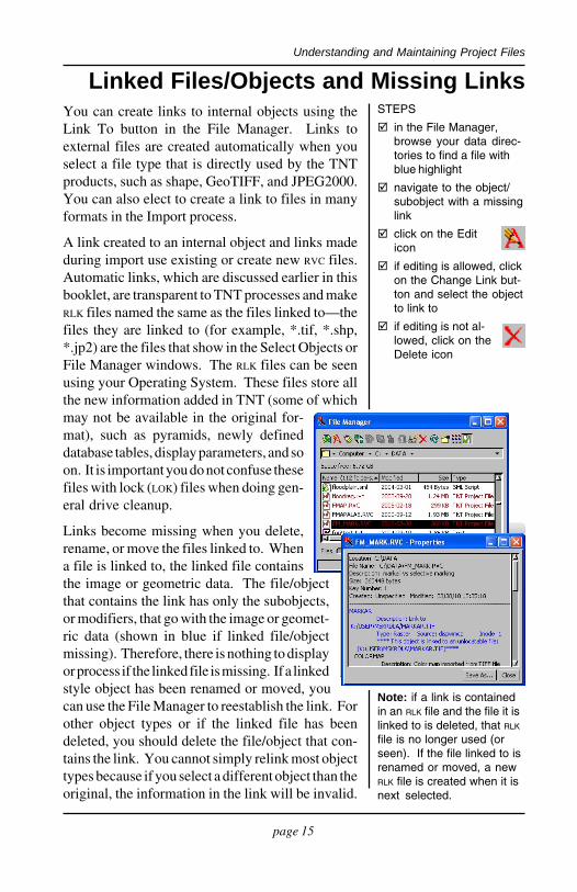
You can create links to internal objects using theLink To button in the File Manager. Links toexternal files are created automatically when youselect a file type that is directly used by the TNTproducts, such as shape, GeoTIFF, and JPEG2000.You can also elect to create a link to files in manyformats in the Import process.
A link created to an internal object and links madeduring import use existing or create new RVC files.Automatic links, which are discussed earlier in thisbooklet, are transparent to TNT processes and makeRLK files named the same as the files linked to—thefiles they are linked to (for example, *.tif, *.shp,*.jp2) are the files that show in the Select Objects orFile Manager windows. The RLK files can be seenusing your Operating System. These files store allthe new information added in TNT (some of whichmay not be available in the original for-mat), such as pyramids, newly defineddatabase tables, display parameters, and soon. It is important you do not confuse thesefiles with lock (LOK) files when doing gen-eral drive cleanup.
Links become missing when you delete,rename, or move the files linked to. Whena file is linked to, the linked file containsthe image or geometric data. The file/objectthat contains the link has only the subobjects,or modifiers, that go with the image or geomet-ric data (shown in blue if linked file/objectmissing). Therefore, there is nothing to displayor process if the linked file is missing. If a linkedstyle object has been renamed or moved, youcan use the File Manager to reestablish the link. Forother object types or if the linked file has beendeleted, you should delete the file/object that con-tains the link. You cannot simply relink most objecttypes because if you select a different object than theoriginal, the information in the link will be invalid.
Linked Files/Objects and Missing LinksSTEPS
in the File Manager,browse your data direc-tories to find a file withblue highlight
navigate to the object/subobject with a missinglink
click on the Editicon
if editing is allowed, clickon the Change Link but-ton and select the objectto link to
if editing is not al-lowed, click on theDelete icon
Note: if a link is containedin an RLK file and the file it islinked to is deleted, that RLK
file is no longer used (orseen). If the file linked to isrenamed or moved, a newRLK file is created when it isnext selected.
page 16
Understanding and Maintaining Project Files
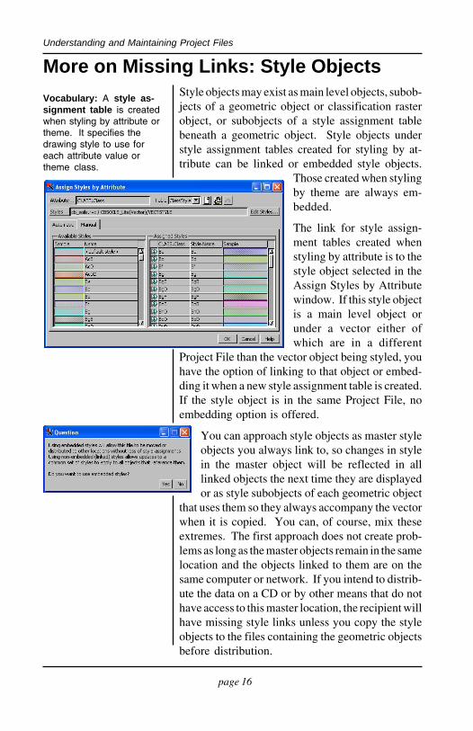
More on Missing Links: Style ObjectsStyle objects may exist as main level objects, subob-jects of a geometric object or classification rasterobject, or subobjects of a style assignment tablebeneath a geometric object. Style objects understyle assignment tables created for styling by at-tribute can be linked or embedded style objects.
Those created when stylingby theme are always em-bedded.
The link for style assign-ment tables created whenstyling by attribute is to thestyle object selected in theAssign Styles by Attributewindow. If this style objectis a main level object orunder a vector either ofwhich are in a different
Project File than the vector object being styled, youhave the option of linking to that object or embed-ding it when a new style assignment table is created.If the style object is in the same Project File, noembedding option is offered.
You can approach style objects as master styleobjects you always link to, so changes in stylein the master object will be reflected in alllinked objects the next time they are displayedor as style subobjects of each geometric object
that uses them so they always accompany the vectorwhen it is copied. You can, of course, mix theseextremes. The first approach does not create prob-lems as long as the master objects remain in the samelocation and the objects linked to them are on thesame computer or network. If you intend to distrib-ute the data on a CD or by other means that do nothave access to this master location, the recipient willhave missing style links unless you copy the styleobjects to the files containing the geometric objectsbefore distribution.
Vocabulary: A style as-signment table is createdwhen styling by attribute ortheme. It specifies thedrawing style to use foreach attribute value ortheme class.
A style object linkedto this style objectis a subobject ofthe style assign-ment table namedabove.
page 17
Understanding and Maintaining Project Files
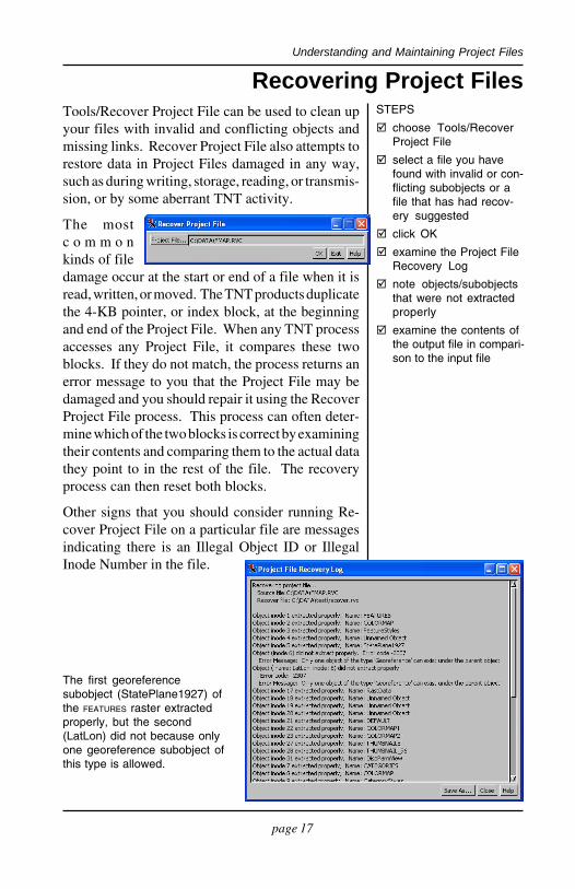
Tools/Recover Project File can be used to clean upyour files with invalid and conflicting objects andmissing links. Recover Project File also attempts torestore data in Project Files damaged in any way,such as during writing, storage, reading, or transmis-sion, or by some aberrant TNT activity.
The mostc o m m o nkinds of filedamage occur at the start or end of a file when it isread, written, or moved. The TNT products duplicatethe 4-KB pointer, or index block, at the beginningand end of the Project File. When any TNT processaccesses any Project File, it compares these twoblocks. If they do not match, the process returns anerror message to you that the Project File may bedamaged and you should repair it using the RecoverProject File process. This process can often deter-mine which of the two blocks is correct by examiningtheir contents and comparing them to the actual datathey point to in the rest of the file. The recoveryprocess can then reset both blocks.
Other signs that you should consider running Re-cover Project File on a particular file are messagesindicating there is an Illegal Object ID or IllegalInode Number in the file.
Recovering Project FilesSTEPS
choose Tools/RecoverProject File
select a file you havefound with invalid or con-flicting subobjects or afile that has had recov-ery suggested
click OK
examine the Project FileRecovery Log
note objects/subobjectsthat were not extractedproperly
examine the contents ofthe output file in compari-son to the input file
The first georeferencesubobject (StatePlane1927) ofthe FEATURES raster extractedproperly, but the second(LatLon) did not because onlyone georeference subobject ofthis type is allowed.

page 18
Understanding and Maintaining Project Files
Notes:

page 19
Understanding and Maintaining Project Files
Notes:
Advanced Software for Geospatial Analysis
www.microimages.com
MicroImages, Inc.
IndexAccess Control Lists .............................. 11Break Lock function .............................. 10conflicting subobjects ............................. 14Copy tool .................................................. 9Delete function ....................................... 10direct use formats .............................. 4, 15Edit tool ..................................................... 7Federal Geographic Data Committee ..... 8invalid subobjects .................................... 14JP2 files ................................... 3, 4, 12, 15link files .......................................... 3, 4, 12lock files (*.lok) ..................................... 10main level object ...................................... 3metadata .................................................... 8missing links ..................................... 15–16
Multi-Copy function ................................ 9object icons ............................................... 5Pack tool ................................................. 10Project File
Properties ............................................. 6structure ................................................ 3tools and functions ....................... 6–11validity ......................................... 13–14
Recover Project File .............................. 17Refresh function ..................................... 10RLK files ........................................... 3, 4, 12shapefiles (*.shp) ........................... 3, 4, 15style objects ...................................... 14, 16TIGER/Line files ...................................... 8
PROJECT
FILES
MicroImages, Inc. publishes a complete line of professional software for advancedgeospatial data visualization, analysis, and publishing. Contact us or visit our web sitefor detailed product information.TNTmips Pro TNTmips Pro is a professional system for fully integrated GIS, image analysis,
CAD, TIN, desktop cartography, and geospatial database management.
TNTmips Basic TNTmips Basic is a low-cost version of TNTmips for small projects.
TNTmips Free TNTmips Free is a free version of TNTmips for students and professionalswith small projects. You can download TNTmips Free from MicroImages’ web site.
TNTedit TNTedit provides interactive tools to create, georeference, and edit vector, image, CAD,TIN, and relational database project materials in a wide variety of formats.
TNTview TNTview has the same powerful display features as TNTmips and is perfect for thosewho do not need the technical processing and preparation features of TNTmips.
TNTatlas TNTatlas lets you publish and distribute your spatial project materials on CD or DVDat low cost. TNTatlas CDs/DVDs can be used on any popular computing platform.