Embed Size (px)
Citation preview
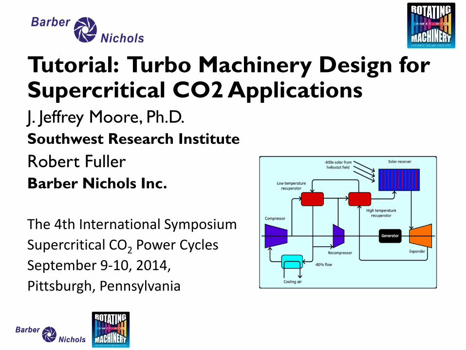
Tutorial: Turbo Machinery Design for Supercritical CO2 Applications J. Jeffrey Moore, Ph.D. Southwest Research Institute Robert Fuller Barber Nichols Inc. The 4th International Symposium Supercritical CO2 Power Cycles September 9-10, 2014, Pittsburgh, Pennsylvania
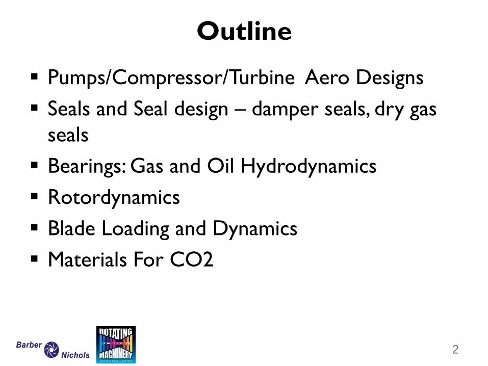
Pumps/Compressor/Turbine Aero Designs Seals and Seal design – damper seals, dry gas
seals Bearings: Gas and Oil Hydrodynamics Rotordynamics Blade Loading and Dynamics Materials For CO2
Outline
2
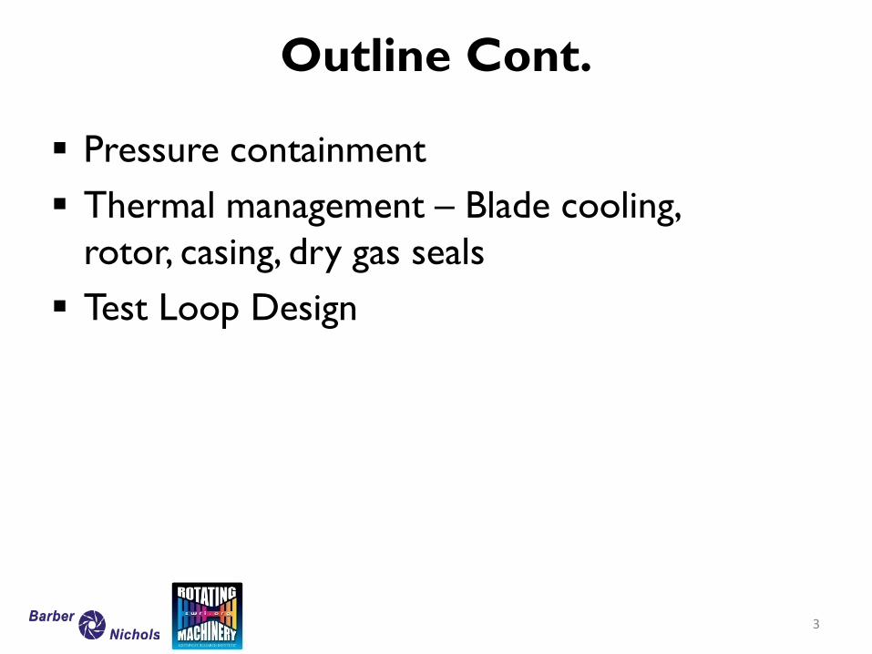
Pressure containment Thermal management – Blade cooling,
rotor, casing, dry gas seals Test Loop Design
Outline Cont.
3
Supercritical CO2 Cycles Pumps/Compressors/Turbines
Aero Design
4
Robert Fuller
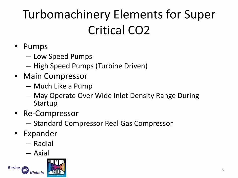
Turbomachinery Elements for Super Critical CO2
• Pumps – Low Speed Pumps – High Speed Pumps (Turbine Driven)
• Main Compressor – Much Like a Pump – May Operate Over Wide Inlet Density Range During
Startup • Re-Compressor
– Standard Compressor Real Gas Compressor • Expander
– Radial – Axial
5
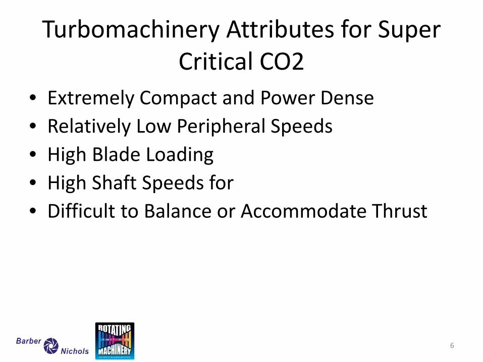
Turbomachinery Attributes for Super Critical CO2
• Extremely Compact and Power Dense • Relatively Low Peripheral Speeds • High Blade Loading • High Shaft Speeds for • Difficult to Balance or Accommodate Thrust
6
Centrifugal Pumps Multi-Stage Typical, Motor Driven
• Low Speed CO2 Pumps, Standard Manufacture – Ruhrpumpen – Flowserve – Sulzer – Wood Group (GE) – Schlumberger
7
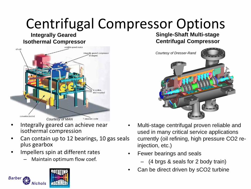
Centrifugal Compressor Options
• Integrally geared can achieve near isothermal compression
• Can contain up to 12 bearings, 10 gas seals plus gearbox
• Impellers spin at different rates – Maintain optimum flow coef.
Integrally Geared Isothermal Compressor
Single-Shaft Multi-stage Centrifugal Compressor
• Multi-stage centrifugal proven reliable and used in many critical service applications currently (oil refining, high pressure CO2 re-injection, etc.)
• Fewer bearings and seals – (4 brgs & seals for 2 body train)
• Can be direct driven by sCO2 turbine
Courtesy of MAN
Courtesy of Dresser-Rand
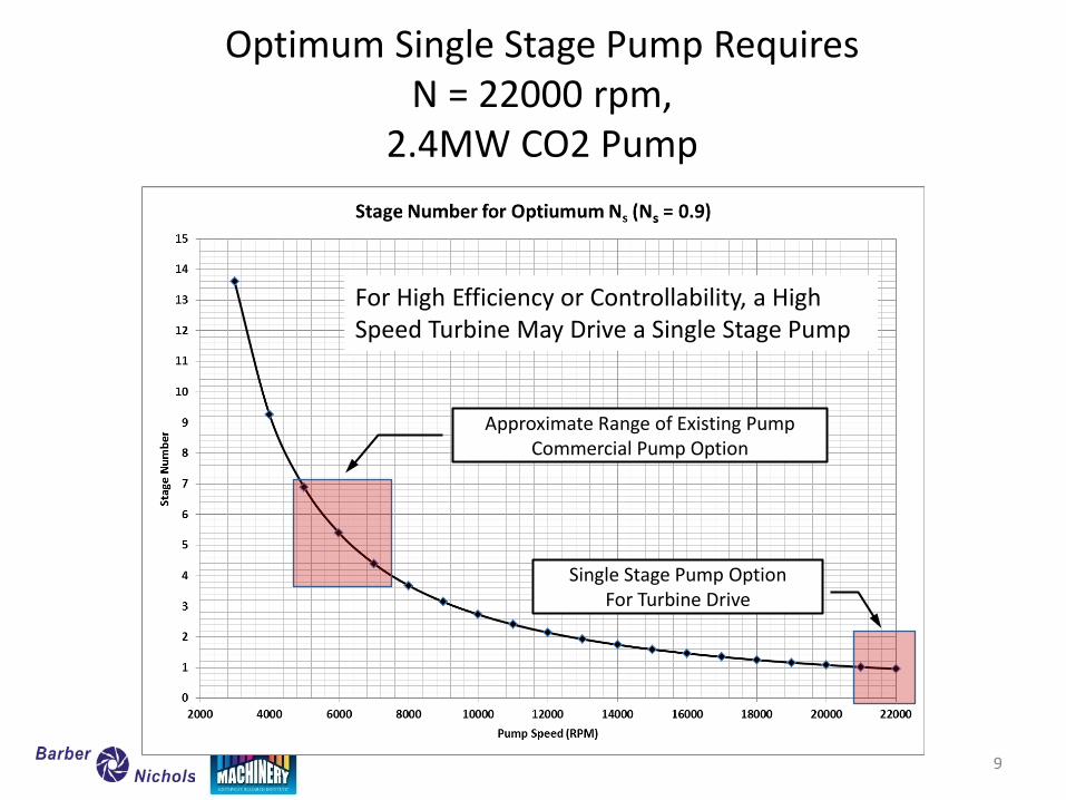
Optimum Single Stage Pump Requires N = 22000 rpm,
2.4MW CO2 Pump
Approximate Range of Existing Pump Commercial Pump Option
Single Stage Pump Option For Turbine Drive
For High Efficiency or Controllability, a High Speed Turbine May Drive a Single Stage Pump
9
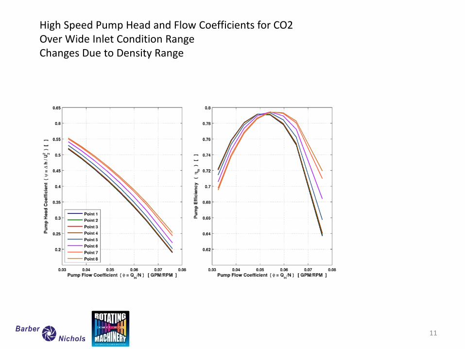
High Speed Pump Head and Flow Coefficients for CO2 Over Wide Inlet Condition Range Changes Due to Density Range
11
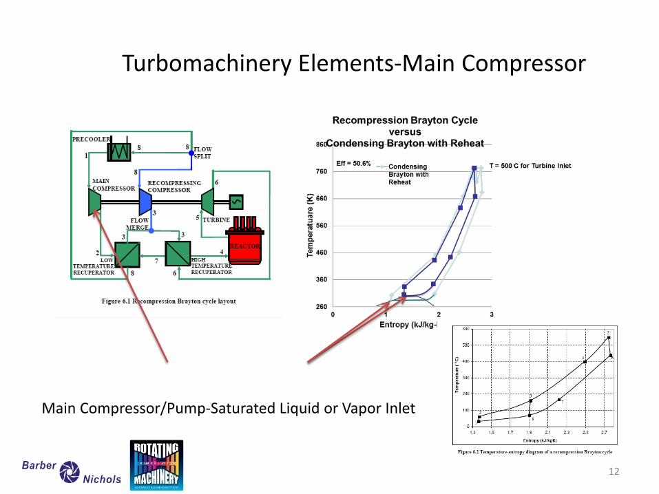
Turbomachinery Elements-Main Compressor
Main Compressor/Pump-Saturated Liquid or Vapor Inlet
12
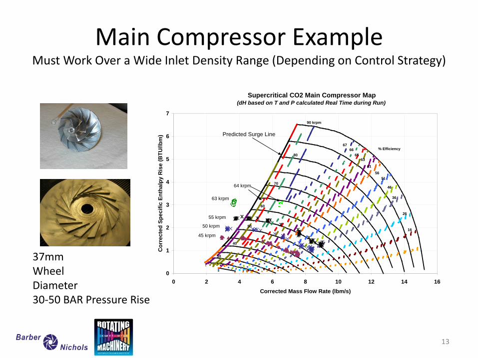
Main Compressor Example Must Work Over a Wide Inlet Density Range (Depending on Control Strategy)
13
Supercritical CO2 Main Compressor Map(dH based on T and P calculated Real Time during Run)
0
1
2
3
4
5
6
7
0 2 4 6 8 10 12 14 16Corrected Mass Flow Rate (lbm/s)
Cor
rect
ed S
peci
fic E
ntha
lpy
Ris
e (B
TU/lb
m)
60
70
80
90 krpm
50
40
30
63 krpm
64 krpm
6766
6563
61
5651
46
36
26
16
55 krpm
50 krpm
45 krpm
% Efficiency
Predicted Surge Line
37mm Wheel Diameter 30-50 BAR Pressure Rise
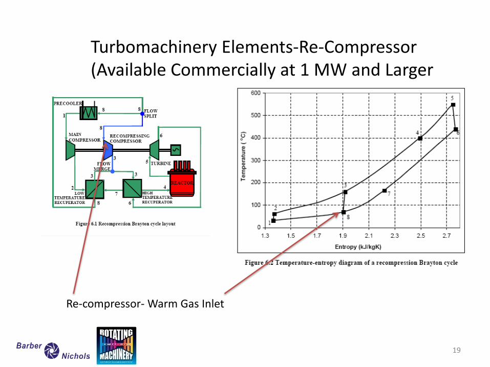
Turbomachinery Elements-Re-Compressor (Available Commercially at 1 MW and Larger
Re-compressor- Warm Gas Inlet
19
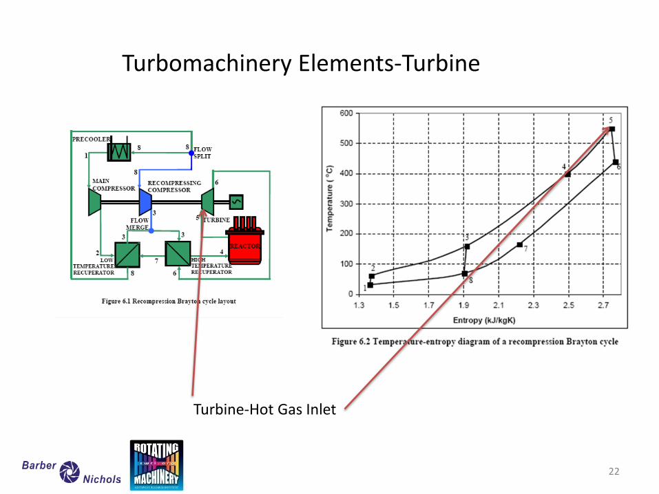
Turbomachinery Elements-Turbine
Turbine-Hot Gas Inlet
22
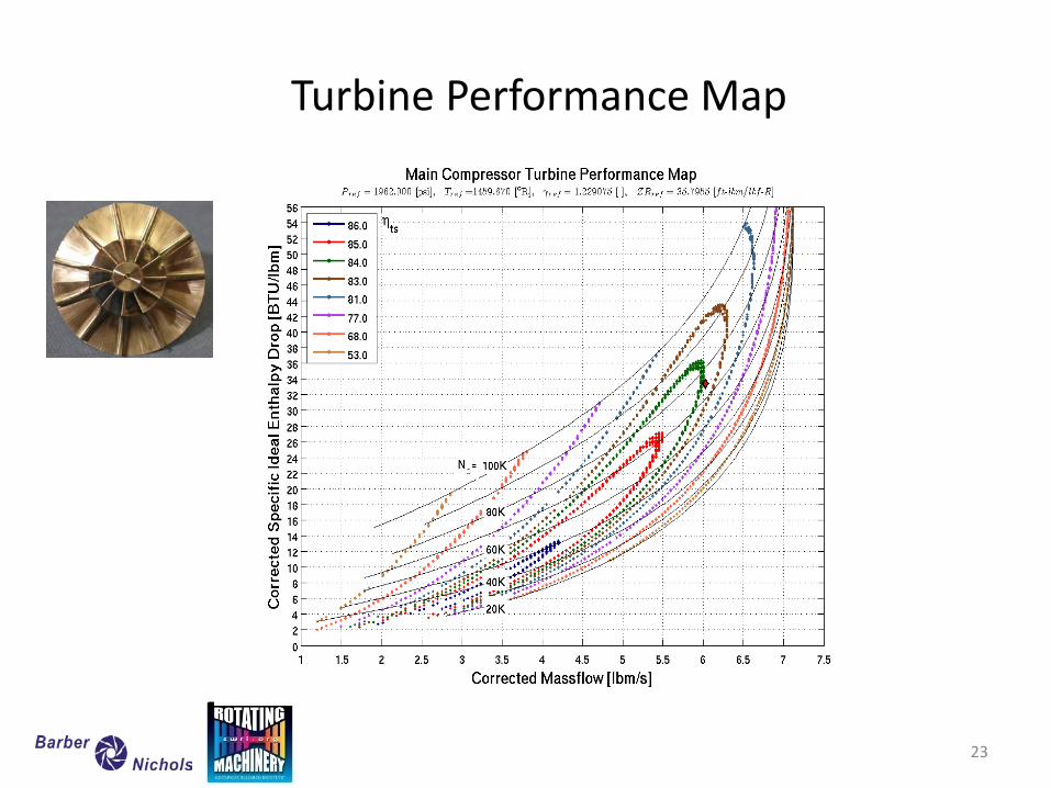
Turbine Performance Map
23
Seals: Internal and Shaft End Jeff Moore
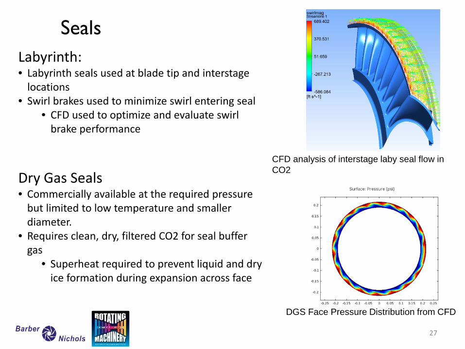
Seals Labyrinth: • Labyrinth seals used at blade tip and interstage
locations • Swirl brakes used to minimize swirl entering seal
• CFD used to optimize and evaluate swirl brake performance
Dry Gas Seals • Commercially available at the required pressure
but limited to low temperature and smaller diameter.
• Requires clean, dry, filtered CO2 for seal buffer gas
• Superheat required to prevent liquid and dry ice formation during expansion across face
CFD analysis of interstage laby seal flow in CO2
DGS Face Pressure Distribution from CFD
27
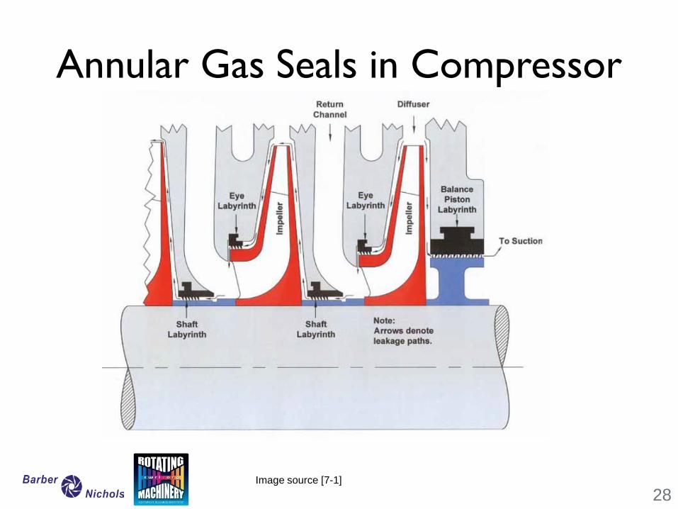
Annular Gas Seals in Compressor
28 Image source [7-1]
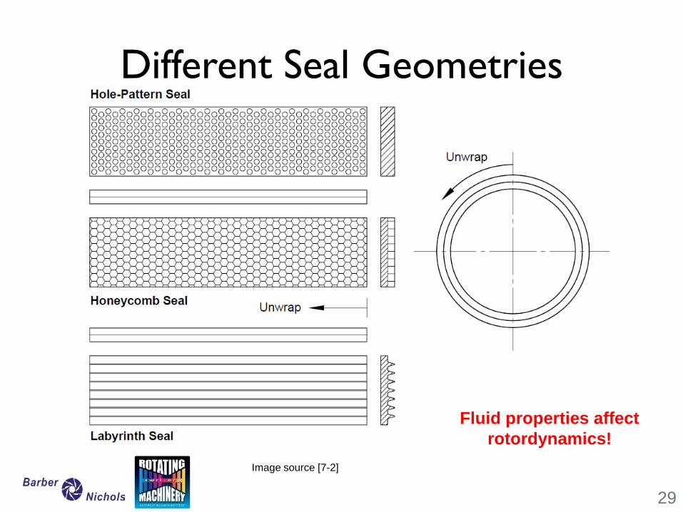
Different Seal Geometries
29
Image source [7-2]
Fluid properties affect rotordynamics!
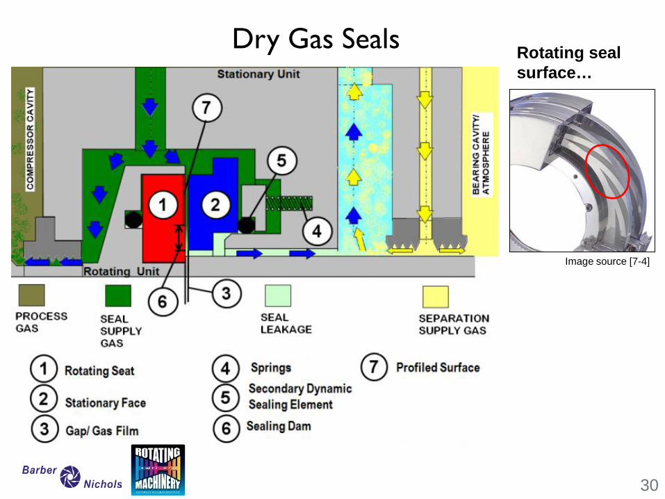
Dry Gas Seals
30
Image source [7-4]
Rotating seal surface…

Bearings
31
Jeff Moore
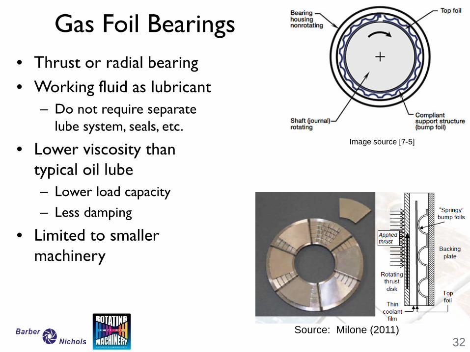
Gas Foil Bearings • Thrust or radial bearing • Working fluid as lubricant
– Do not require separate lube system, seals, etc.
• Lower viscosity than typical oil lube – Lower load capacity – Less damping
• Limited to smaller machinery
32
Image source [7-5]
Source: Milone (2011)
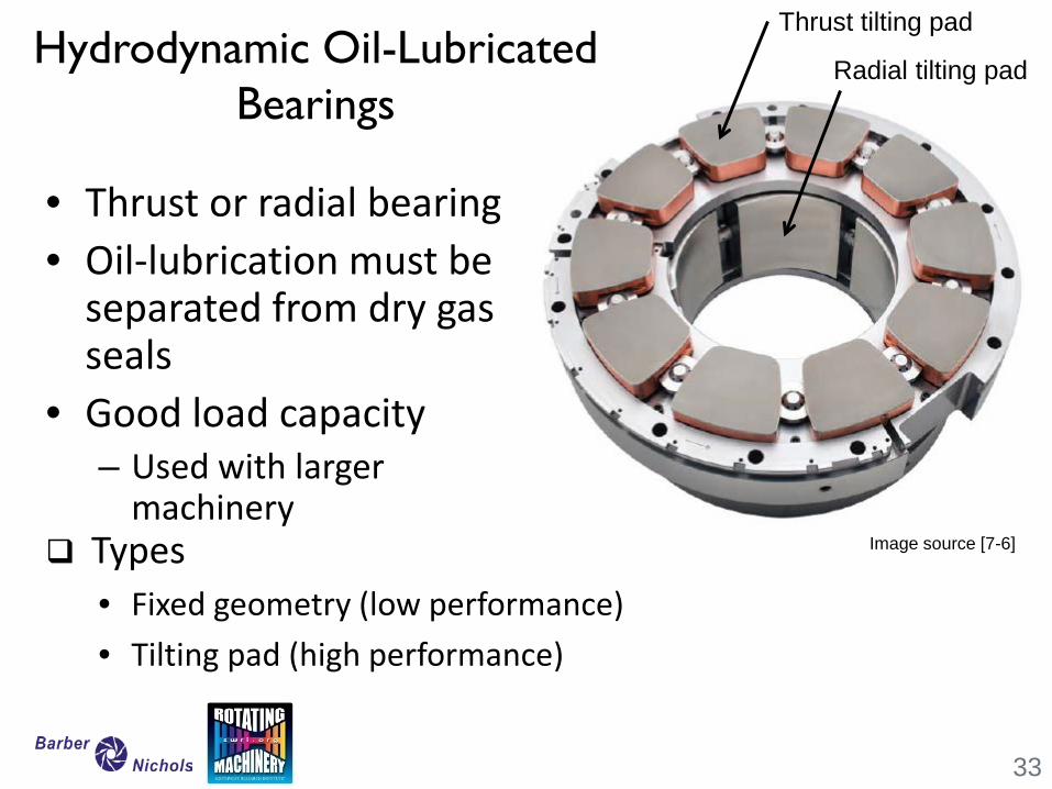
Hydrodynamic Oil-Lubricated Bearings
• Thrust or radial bearing • Oil-lubrication must be
separated from dry gas seals
• Good load capacity – Used with larger
machinery
33
Image source [7-6]
Thrust tilting pad
Radial tilting pad
Types • Fixed geometry (low performance) • Tilting pad (high performance)
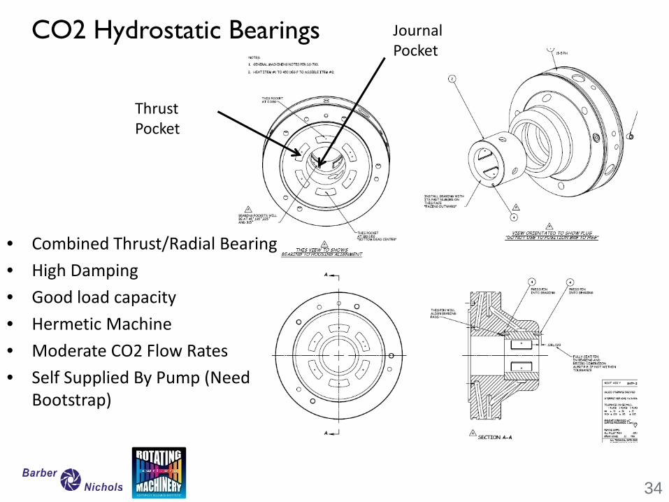
CO2 Hydrostatic Bearings
• Combined Thrust/Radial Bearing • High Damping • Good load capacity • Hermetic Machine • Moderate CO2 Flow Rates • Self Supplied By Pump (Need
Bootstrap)
34
Thrust Pocket
Journal Pocket

Rotordynamics
Jeff Moore
Rotordynamics
1
1.5
2
2.5
3
3.5
4
0 2 4 6 8
CSR
Average Gas Density (lbm/ft3)
Region A
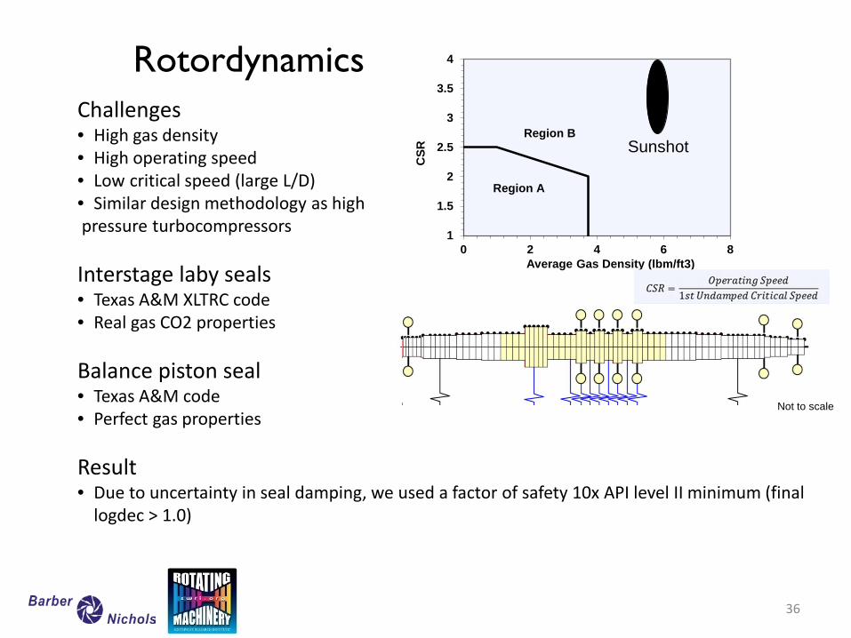
Region B Challenges • High gas density • High operating speed • Low critical speed (large L/D) • Similar design methodology as high pressure turbocompressors
Interstage laby seals • Texas A&M XLTRC code • Real gas CO2 properties Balance piston seal • Texas A&M code • Perfect gas properties Result • Due to uncertainty in seal damping, we used a factor of safety 10x API level II minimum (final
logdec > 1.0)
Sunshot
Not to scale
36
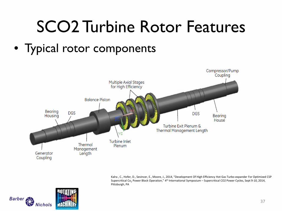
SCO2 Turbine Rotor Features • Typical rotor components
37
Kalra , C., Hofer, D., Sevincer, E., Moore, J., 2014, “Development Of High Efficiency Hot Gas Turbo-expander For Optimized CSP Supercritical Co2 Power Block Operation,” 4th International Symposium – Supercritical CO2 Power Cycles, Sept 9-10, 2014, Pittsburgh, PA
38
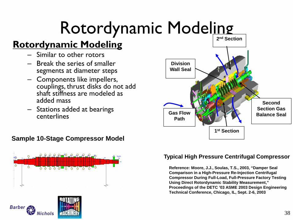
Rotordynamic Modeling Rotordynamic Modeling
– Similar to other rotors – Break the series of smaller
segments at diameter steps – Components like impellers,
couplings, thrust disks do not add shaft stiffness are modeled as added mass
– Stations added at bearings centerlines
Second Section Gas Balance Seal
Division Wall Seal
2nd Section
1st Section
Gas Flow Path
Typical High Pressure Centrifugal Compressor
Sample 10-Stage Compressor Model
Shaft179
7570
656055504540
3530252015105
haft11
Reference: Moore, J.J., Soulas, T.S., 2003, “Damper Seal Comparison in a High-Pressure Re-Injection Centrifugal Compressor During Full-Load, Full-Pressure Factory Testing Using Direct Rotordynamic Stability Measurement,” Proceedings of the DETC ’03 ASME 2003 Design Engineering Technical Conference, Chicago, IL, Sept. 2-6, 2003
39
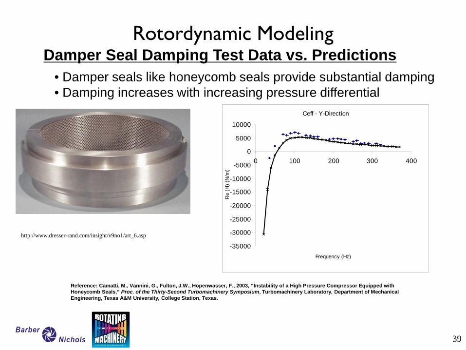
Rotordynamic Modeling
Ceff - Y-Direction
-35000
-30000
-25000
-20000
-15000
-10000
-5000
0
5000
10000
0 100 200 300 400
Frequency (Hz)
Re
(H) (
N/m
)
Damper Seal Damping Test Data vs. Predictions
Reference: Camatti, M., Vannini, G., Fulton, J.W., Hopenwasser, F., 2003, “Instability of a High Pressure Compressor Equipped with Honeycomb Seals,” Proc. of the Thirty-Second Turbomachinery Symposium, Turbomachinery Laboratory, Department of Mechanical Engineering, Texas A&M University, College Station, Texas.
• Damper seals like honeycomb seals provide substantial damping • Damping increases with increasing pressure differential
http://www.dresser-rand.com/insight/v9no1/art_6.asp
40
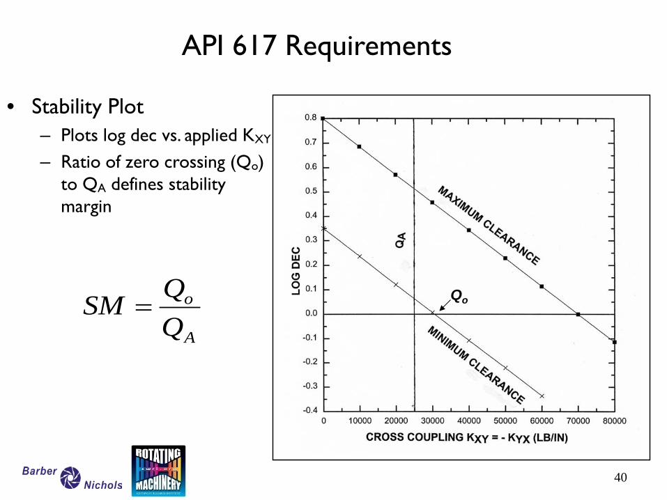
API 617 Requirements
• Stability Plot – Plots log dec vs. applied KXY
– Ratio of zero crossing (Qo) to QA defines stability margin
A
o
QQSM = Qo
41
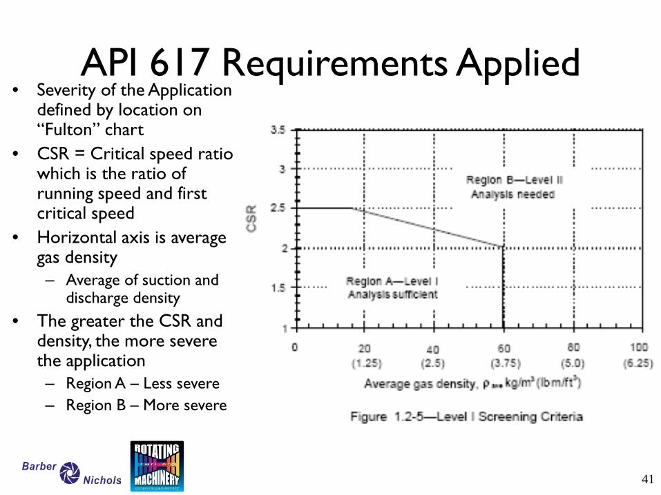
API 617 Requirements Applied • Severity of the Application
defined by location on “Fulton” chart
• CSR = Critical speed ratio which is the ratio of running speed and first critical speed
• Horizontal axis is average gas density – Average of suction and
discharge density • The greater the CSR and
density, the more severe the application – Region A – Less severe – Region B – More severe
42
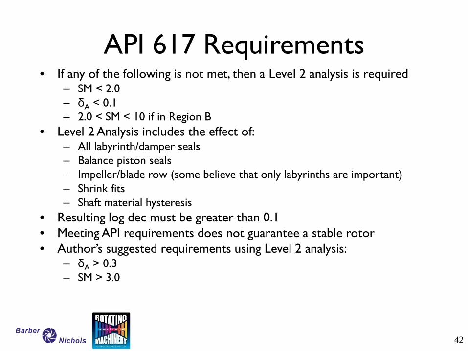
API 617 Requirements • If any of the following is not met, then a Level 2 analysis is required
– SM < 2.0 – δA < 0.1 – 2.0 < SM < 10 if in Region B
• Level 2 Analysis includes the effect of: – All labyrinth/damper seals – Balance piston seals – Impeller/blade row (some believe that only labyrinths are important) – Shrink fits – Shaft material hysteresis
• Resulting log dec must be greater than 0.1 • Meeting API requirements does not guarantee a stable rotor • Author’s suggested requirements using Level 2 analysis:
– δA > 0.3 – SM > 3.0
Blade Dynamics
Jeff Moore
High gas density and machine power density results in large blade loading – Gas forces need to be considered in addition to
centrifugal loads – Blade-to-disk attachment requires special
consideration High gas density also amplifies unsteady wake
interaction forces on blades – Critical to avoid resonance – Non-harmonic excitation from gas separation
should be avoided
Blade Loading and Dynamics
45
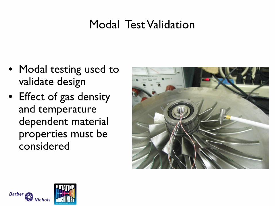
Modal Test Validation
• Modal testing used to validate design
• Effect of gas density and temperature dependent material properties must be considered
Supercritical CO2 Cycles Materials
47
Robert Fuller
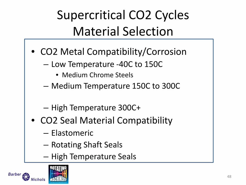
Supercritical CO2 Cycles Material Selection
• CO2 Metal Compatibility/Corrosion – Low Temperature -40C to 150C
• Medium Chrome Steels – Medium Temperature 150C to 300C
– High Temperature 300C+
• CO2 Seal Material Compatibility – Elastomeric – Rotating Shaft Seals – High Temperature Seals
48
CO2 Corrosion
• Oil Business – Pipeline Corrosion
• Usually due to water or other constituents
• Specific to SCO2 Power – MIT – Oakridge NL – Sandia NL – University of Wisconsin
49
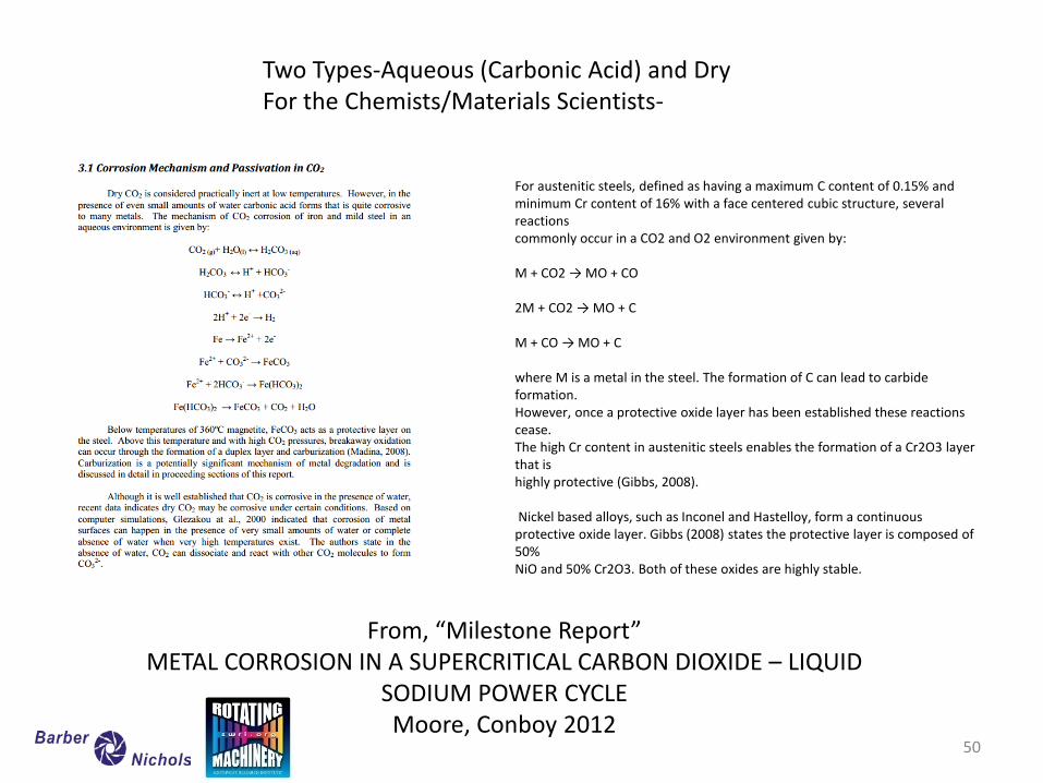
For austenitic steels, defined as having a maximum C content of 0.15% and minimum Cr content of 16% with a face centered cubic structure, several reactions commonly occur in a CO2 and O2 environment given by: M + CO2 → MO + CO 2M + CO2 → MO + C M + CO → MO + C where M is a metal in the steel. The formation of C can lead to carbide formation. However, once a protective oxide layer has been established these reactions cease. The high Cr content in austenitic steels enables the formation of a Cr2O3 layer that is highly protective (Gibbs, 2008). Nickel based alloys, such as Inconel and Hastelloy, form a continuous protective oxide layer. Gibbs (2008) states the protective layer is composed of 50% NiO and 50% Cr2O3. Both of these oxides are highly stable.
Two Types-Aqueous (Carbonic Acid) and Dry For the Chemists/Materials Scientists-
From, “Milestone Report” METAL CORROSION IN A SUPERCRITICAL CARBON DIOXIDE – LIQUID
SODIUM POWER CYCLE Moore, Conboy 2012
50
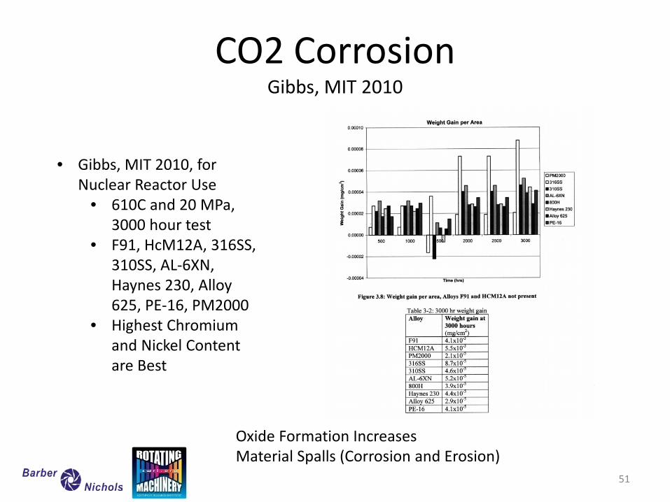
CO2 Corrosion Gibbs, MIT 2010
• Gibbs, MIT 2010, for Nuclear Reactor Use
• 610C and 20 MPa, 3000 hour test
• F91, HcM12A, 316SS, 310SS, AL-6XN, Haynes 230, Alloy 625, PE-16, PM2000
• Highest Chromium and Nickel Content are Best
Oxide Formation Increases Material Spalls (Corrosion and Erosion)
51
52
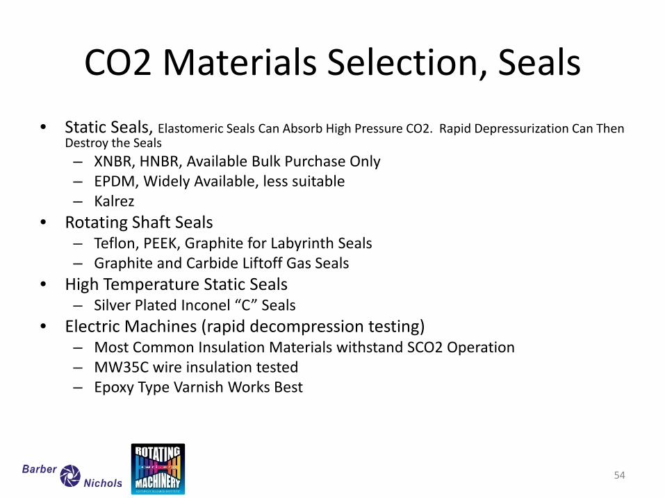
CO2 Materials Selection, Seals • Static Seals, Elastomeric Seals Can Absorb High Pressure CO2. Rapid Depressurization Can Then
Destroy the Seals – XNBR, HNBR, Available Bulk Purchase Only – EPDM, Widely Available, less suitable – Kalrez
• Rotating Shaft Seals – Teflon, PEEK, Graphite for Labyrinth Seals – Graphite and Carbide Liftoff Gas Seals
• High Temperature Static Seals – Silver Plated Inconel “C” Seals
• Electric Machines (rapid decompression testing) – Most Common Insulation Materials withstand SCO2 Operation – MW35C wire insulation tested – Epoxy Type Varnish Works Best
54
Supercritical CO2 Cycles Pressure Containment
55
Robert Fuller
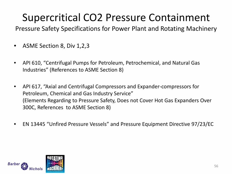
Supercritical CO2 Pressure Containment Pressure Safety Specifications for Power Plant and Rotating Machinery
• ASME Section 8, Div 1,2,3 • API 610, “Centrifugal Pumps for Petroleum, Petrochemical, and Natural Gas
Industries” (References to ASME Section 8) • API 617, “Axial and Centrifugal Compressors and Expander-compressors for
Petroleum, Chemical and Gas Industry Service” (Elements Regarding to Pressure Safety, Does not Cover Hot Gas Expanders Over 300C, References to ASME Section 8)
• EN 13445 “Unfired Pressure Vessels” and Pressure Equipment Directive 97/23/EC
56
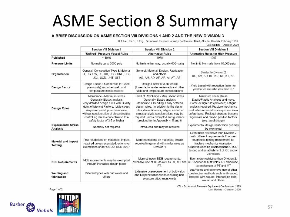
ASME Section 8 Summary
57
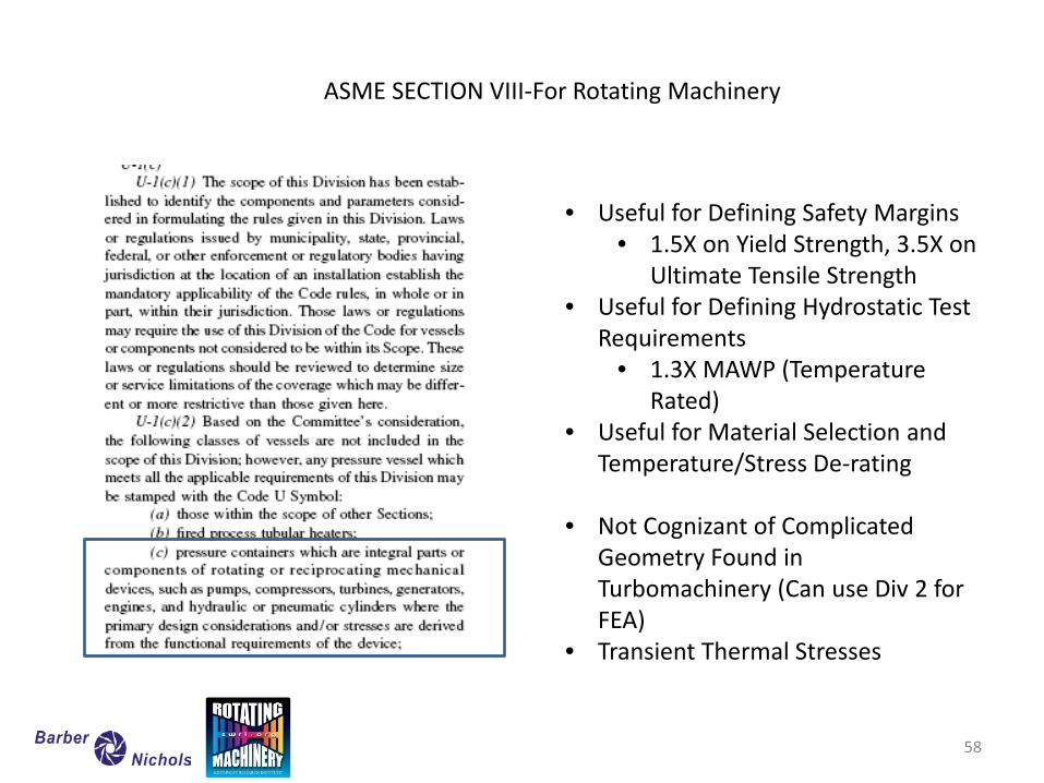
ASME SECTION VIII-For Rotating Machinery
• Useful for Defining Safety Margins • 1.5X on Yield Strength, 3.5X on
Ultimate Tensile Strength • Useful for Defining Hydrostatic Test
Requirements • 1.3X MAWP (Temperature
Rated) • Useful for Material Selection and
Temperature/Stress De-rating
• Not Cognizant of Complicated Geometry Found in Turbomachinery (Can use Div 2 for FEA)
• Transient Thermal Stresses
58
59 59
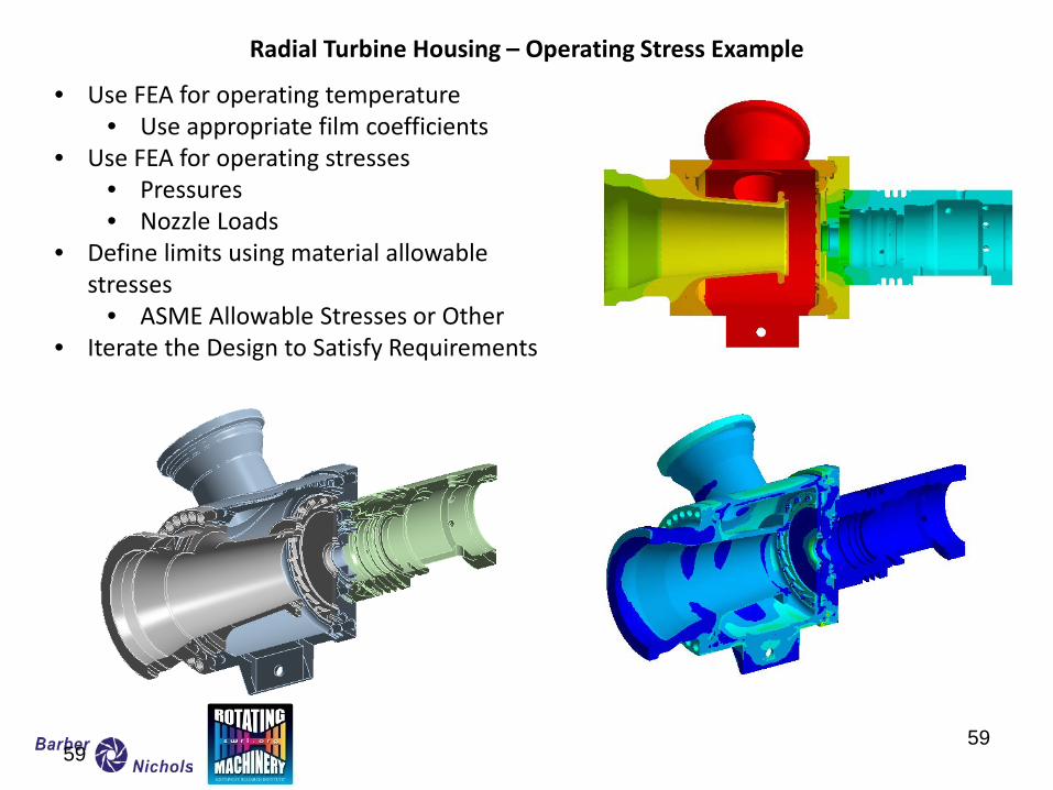
Radial Turbine Housing – Operating Stress Example
• Use FEA for operating temperature • Use appropriate film coefficients
• Use FEA for operating stresses • Pressures • Nozzle Loads
• Define limits using material allowable stresses
• ASME Allowable Stresses or Other • Iterate the Design to Satisfy Requirements
60 60
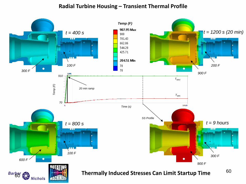
Radial Turbine Housing – Transient Thermal Profile
t = 400 s t = 1200 s (20 min)
t = 800 s t = 9 hours
Time (s)
Tem
p (F
)
TMIN
TMAX
SS Profile
Temp (F)
20 min ramp
70
910
600 F
100 F
300 F 100 F
900 F
200 F
900 F
300 F
Thermally Induced Stresses Can Limit Startup Time
Thermal Management
Jeff Moore
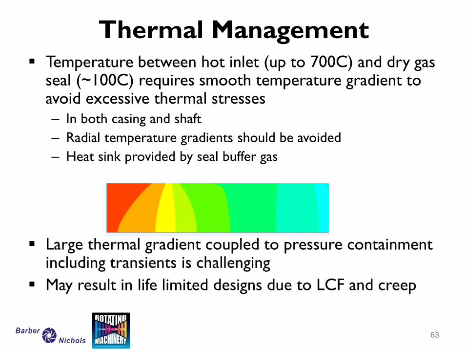
Temperature between hot inlet (up to 700C) and dry gas seal (~100C) requires smooth temperature gradient to avoid excessive thermal stresses – In both casing and shaft – Radial temperature gradients should be avoided – Heat sink provided by seal buffer gas
Large thermal gradient coupled to pressure containment including transients is challenging
May result in life limited designs due to LCF and creep
Thermal Management
63

Test Loop Design
Jeff Moore
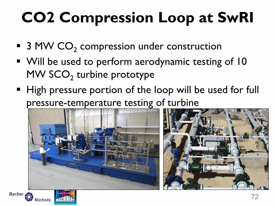
3 MW CO2 compression under construction Will be used to perform aerodynamic testing of 10
MW SCO2 turbine prototype High pressure portion of the loop will be used for full
pressure-temperature testing of turbine
CO2 Compression Loop at SwRI
72
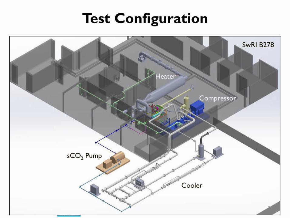
Test Configuration
73
SwRI B278
Heater
sCO2 Pump
Compressor
Cooler
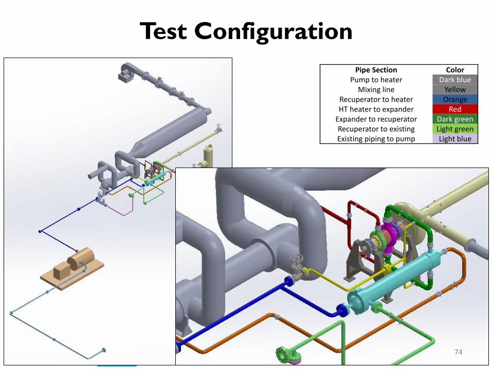
Test Configuration
74
Pipe Section Color Pump to heater Dark blue
Mixing line Yellow Recuperator to heater Orange HT heater to expander Red
Expander to recuperator Dark green Recuperator to existing Light green Existing piping to pump Light blue
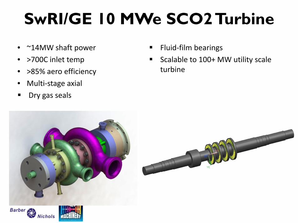
• ~14MW shaft power • >700C inlet temp • >85% aero efficiency • Multi-stage axial Dry gas seals
Fluid-film bearings Scalable to 100+ MW utility scale
turbine
SwRI/GE 10 MWe SCO2 Turbine

Summary
Jeff Moore
SCO2 Cycle can Provide over 50% Thermal Efficiency SCO2 Turbomachinery Require Additional Considerations Real gas properties important for aero prediction and
rotordynamics Gas density high – rotordynamics and blade dynamics High heat transfer – thermal management and pressure
containment Material compatibility – high temperature and seals Requires design that can accommodate high thermal
gradients with high pressure containment High power density results in challenges in packaging and
driven equipment matching.
Summary