Embed Size (px)
Citation preview

Journal of Physics B Atomic Molecular and Optical Physics
TUTORIAL bull OPEN ACCESS
Preparation of cold molecules for high-precisionmeasurementsTo cite this article T E Wall 2016 J Phys B At Mol Opt Phys 49 243001
View the article online for updates and enhancements
You may also likeWelding Characteristics of 67 kHzUltrasonic Plastic Welding System UsingFundamental and Higher-Resonance-Frequency VibrationsMisugi Hongoh Masafumi YoshikuniHidekazu Hashii et al
-
Nonlinear Waves in Thin Magnetic FluxTubes in Astrophysical PlasmaY D Zhugzhda
-
Welding Characteristics of 40 kHzUltrasonic Plastic Welding System UsingFundamental and Higher-Resonance-Frequency VibrationsMisugi Hongoh Eri Iwase Hidenori Tsuboiet al
-
This content was downloaded from IP address 6521228167 on 28012022 at 1437
Tutorial
Preparation of cold molecules forhigh-precision measurements
T E Wall
Centre for Cold Matter Blackett Laboratory Imperial College London Prince Consort Road LondonSW7 2AZ UK
E-mail twallimperialacuk
Received 12 October 2014 revised 20 May 2016Accepted for publication 7 June 2016Published 25 November 2016
AbstractMolecules can be used to test fundamental physics Such tests often require cold molecules fordetailed spectroscopic analysis Cooling internal degrees of freedom provides a high level ofstate-selectivity with large populations in the molecular states of interest Cold translationalmotion allows slow bright beams to be created allowing long interaction times In this tutorialarticle we describe the common techniques for producing cold molecules for high-precisionspectroscopy experiments For each technique we give examples of its application inexperiments that use molecular structure to probe fundamental physics choosing one experimentin particular as a case study We then discuss a number of new techniques some currently underdevelopment others proposed that promise high flux sources of cold molecules applicable toprecise spectroscopic tests of fundamental physics
Keywords cold molecules precision spectroscopy molecular structure
(Some figures may appear in colour only in the online journal)
1 Introduction
lsquoA diatomic molecule has one atom too manyrsquo This judge-ment attributed to Arthur Schawlow [1] conveys the antip-athy that a physicist might feel towards the complexity ofmolecular structure However hidden within this complexityis great sensitivity making molecules very useful systems forprobing fundamental physics sometimes far more sensitivethan atoms From a careful study of molecular structure onecan observe subtle effects with significant consequences suchas the shape of the electron the time-variation of fundamentalconstants and the fundamental symmetries of our Universe
In order to observe these effects a very careful inter-rogation of molecular structure is necessary which requiressources of molecules that are well characterised repeatable
which produce an intense high purity flux of the chosenmolecule It is often advantageous for the molecules to becold and slow offering a high level of state selectivity andaffording long interaction times with low divergence beamslsquoColdrsquo refers here to all degrees of freedom the translationalmotion as well as the electronic vibrational and rotationalmotion
In this article we discuss the main techniques used toproduce cold molecules for high-precision measurements Foreach of these we discuss the application of the technique inspectroscopy experiments and choose one experiment for amore detailed discussion describing the role and importanceof the preparation method In section 2 we discuss the prep-aration of cold molecules through supersonic expansionAfter describing the basic principles of supersonic expansionand a brief technical review of the most commonly usedmethods of creating pulsed molecular beams we describe indetail an experiment in which a beam of CH molecules wasused in a precise investigation of a possible variation of thefine structure constant and proton-to-electron mass ratio [2]
Journal of Physics B Atomic Molecular and Optical Physics
J Phys B At Mol Opt Phys 49 (2016) 243001 (37pp) doi1010880953-40754924243001
Original content from this work may be used under the termsof the Creative Commons Attribution 30 licence Any
further distribution of this work must maintain attribution to the author(s) andthe title of the work journal citation and DOI
0953-407516243001+37$3300 copy 2016 IOP Publishing Ltd Printed in the UK1
In section 3 we describe methods to slow down moleculesdescribing in detail the method of Stark deceleration We thendiscuss an experiment in which precise spectroscopy wasperformed with Stark decelerated OH molecules whichwhen combined with astrophysical data can place a con-straint on the variation of the fine structure constant over atime scale of 10Gyr with a sensitivity of 1 ppm [3] Insection 4 the method of buffer gas cooling is described Thistechnique in which molecules are cooled in a cryogenicenvironment can be used to produce intense beams of slowmolecules In particular we describe an experiment in whichThO molecules from a buffer gas source were used to performthe most precise measurement to date of the electric dipolemoment (EDM) of the electron [4] In section 5 we discussnewer techniques some still under development which havenot yet been used in high-precision spectroscopy but whichshow great promise in this field This section includes adescription of a new technique in deceleration (travellingwave deceleration) methods of trapping molecules velocityselection using electric or magnetic guides and the produc-tion of slow molecules using mechanical methods (using acounter-rotating nozzle or an lsquoatomic paddlersquo) Excitingresults are presented in which cold and ultra-cold moleculeswere produced by direct laser cooling and by Sisyphuscooling
This tutorial article is not an exhaustive review of tech-niques in the field of cold molecules1 but will give a peda-gogical description of those methodologies useful to precisespectroscopy Methods of producing cold molecules aretypically divided into two categories (i) lsquodirectrsquo methods inwhich an ensemble of molecules is cooled and (ii) lsquoindirectrsquomethods in which atoms are laser cooled and then combinedto form ultra-cold molecules In this article we discuss onlylsquodirect rsquo methods as many of these techniques are useful forpreparing molecules for precise spectroscopic tests of fun-damental physics There has been much work in the pro-duction of ultra-cold molecules through indirect methodsphoto-association (see [14ndash16] and references therein) andmagneto-association (see [17ndash19] and references therein) andit is a significant ongoing field of activity While these tech-niques have been able to to produce molecular ensemblestypically much colder than many of the lsquodirectrsquo approaches(for example see figure 1 of [8] for a graphical comparison)the range of species produced has been limited with muchwork concentrating on bialkali dimers The application ofthese lsquoindirectrsquo approaches to precise spectroscopic studies offundamental physics has hitherto been limited However theprospect of using indirectly cooled molecules in precisemeasurements has been considered Zelevinsky et al haveproposed a measurement of the proton-to-electron mass ratioby probing vibrational energy intervals of ultra-cold Sr2molecules formed by photoassociation and confined in anoptical lattice [20] Recently McGuyer et al have performedprecise spectroscopy of Sr2 molecules in a lattice [21] Rabioscillations between different vibrational states were driven
with linewdiths on the order of 100Hz measured allowingthe precise determination of ground state binding energydifferences This work demonstrates the great potential forperforming precise spectroscopy with ultra-cold moleculescreated by lsquoindirectrsquo methods
In this article we focus on the production of slowmolecules for tests of physics with highly precise spectrosc-opy However cold molecules are of great interest in otherfields of research such as cold chemistry [22ndash24] andquantum information processing [25 26] The study of coldcontrolled chemistry has long been of great interest [27] andis now a very active discipline (see [23] and referencestherein) Great control can be exerted over cold atoms andmolecules allowing the detailed study of scattering andreaction dynamics Many of the methods and techniquesuseful for precise spectroscopy are also relevant in coldchemistry and scattering experiments including the study ofreactions in supersonic molecular beams [28ndash30] studies ofcollisions with Stark- and Zeeman-decelerated beams[11 31 32] and with merged beams prepared using magneticand electric guides [33ndash35] and the investigation of collisionswith counter-propagating molecular packets confined in amolecular synchrotron [36 37]
The application of cold and ultra-cold molecules toquantum computation has been proposed [25 26 38]Experimentally this is an emerging field and many of themethods described in this tutorial have the potential to pro-vide sources of ultra-cold confined molecules for use in aquantum processor
2 Supersonic beams
Supersonic beams can produce high-density sources of fastbut cold molecules They are very versatile and have beenused in many experiments both directly as a source ofmolecules for an experiment or as a supply of molecules thatcan be further slowed and cooled by other techniques Inorder to create a supersonic beam gas initially held at highpressure p0 (~1 bar) and temperature T0 (typically roomtemperature but this can be reduced) is allowed to expandinto a vacuum chamber (typically held at pressure
~ -p 10V7 mbar) through a pulsed valve cooling all
degrees of freedom as it does so Before the valve is openedthe gas has no net flow (the average speed of the molecules iszero) but has random thermal motion Collisions between themolecules during the expansion inside the vacuum chambercool the translational vibrational and rotational degrees offreedom During the supersonic expansion process a gas withan initially wide speed distribution but no net flow becomes ajet with a narrow velocity distribution but travelling quicklyalong the beam-axis (defined as the z-axis in this article)typically at several hundred metres per second As the jetexpands into the vacuum chamber the gas pressure reducesuntil eventually the pressure is so low that there are no morecollisions between the molecules At this point the jet hasreached its terminal speed and temperature A full description
1 Several reviews exist which give detailed descriptions of certaintechniques or an overview of the field of cold molecules [5ndash13]
2
J Phys B At Mol Opt Phys 49 (2016) 243001 Tutorial
of the dynamics that occur in a supersonic expansion can befound in [39 40]
The principle of supersonic expansion can be describedin terms of the thermodynamics of an expanding ideal gasConsider two isolated chambers separated by a wall with onechamber containing gas held at pressure p0 and temperatureT0 and the second chamber held at much lower pressurep p1 0 Let a small opening be made in the wall The high
pressure gas flows into the second chamber with macroscopicflow speed v During the expansion no heat is added to thegas D =Q 0 but it does work
D = -W p V p V 11 1 0 0 ( )
whereV0 1 is the gas volume in the firstsecond chamber Thechange in the total internal energy of the expanding gas is
D = + -U U m v U1
2 2t1
20 ( )
where U0 1 is the total internal energy of the gas in the firstsecond chamber and mt is the total mass of the flowing gasFrom the first law of thermodynamics for a process in whichD =Q 0 the expressions in equations (1) and (2) are equalCombining these gives the forward speed of the flowing gas
= -v h h2 30 1( ) ( )
where h is the specific enthalpy ( = +h U pVm
1
mol( ) for an
ideal gas with molecular mass mmol) The specific enthalpycan be described in terms of the specific heat capacity of an
ideal gas held at constant pressure = parapara
cph
T p( ) Assuming cp
to be constant yields the following expression for the forwardspeed
= -v c T T2 4p 0 1( ) ( )
It can be shown from the ideal gas law that
gg
=-
ck
m 1 5p
B
mol ( )( )
where g = c cp v is the specific heat ratio g = 5 3 for anideal monatomic gas and g = 7 5 for a diatomic moleculeprovided that the rotational excitation is appreciable at theinitial temperature but not the vibrational excitation
As the gas expands its internal dynamics cool throughcollisions transferring rotational and vibrational energy intothe forward flow speed This process continues until thepressure has dropped such that there are no more collisions atwhich point the gas jet has reached its terminal speed vtgiven by combining the expressions in (4) and (5)
gg
=-
-v
k T T
m
2
1 6t
B 0 1
mol
( ) ( )
where T1 (T0) is the final translational temperature of the jetAfter expansion the beam typically traverses a skimmer witha small aperture which limits the transverse speed distribu-tion of the beam The terminal translational temperature of thebeam parallel to the forward flow speed T1 scales with the
initial temperature and pressure and the nozzle diameter d as
micro acute a-T T P d 71 0 0( ) ( )
where a g g= - +6 1 2( ) ( ) [41 42]As examples a supersonic beam of helium made from a
high pressure reservoir at room temperature will reach aterminal speed of 1765m sminus1 and a beam of NO radicals willreach a speed of 760m sminus1 The dependence of the terminalspeed on the specific heat ratio leads to molecules reaching agreater speed than atoms (of comparable mass) as themoleculesrsquo rotational and vibrational energy is transferred tokinetic energy Often molecules will be lsquoseededrsquo in a carriergas of atoms (typically noble gases) which determines theforward speed of the beam For example in [43] YbF radicalswere seeded in He Ar and Xe resulting in beams with for-ward speeds of 1735m sminus1 580m sminus1 and 325m sminus1
respectively In this case the YbF radicals were made by thesupersonic expansion of a ~5 bar mixture of 2 SF6 98carrier gas and laser ablation of Yb The gas mixture wasexpanded into a vacuum chamber (maintained at a pressure ofaround -10 7 mbar when the valve was not in operation risingto a time-averaged pressure of around acute -5 10 4 mbar withthe valve operated at 10Hz) through a pulsed valve A rod ofYb metal was located immediately downstream of the valvenozzle Ablation of the rod by radiation from a NdYAG laser(up to 35mJ at 1064nm) produced a hot plume of Yb atomswhich reacted with the SF6 in the pulsed gas beam formingYbF radicals which became entrained in the carrier gas pulseThe speeds for the Ar and Xe beams were measured to beslightly greater than those calculated from (6) (552m sminus1 and305m sminus1 respectively) The authors suggest that this couldhave been the result of heating inside the pulsed valve
In a seeded beam in which the source density is high theresulting supersonic expansion is the same as would beachieved for a pure gas in which the molecular mass and heatcapacity are equal to the weighted means of those in themixture [44] In this case both species in the beam end uptravelling at the same speed and with the same translationaltemperature If the source density is too low however thereare not enough collisions during the expansion for both spe-cies to equilibrate If the seed and carrier species have adifferent molecular mass then they will reach differentterminal speeds an effect known as lsquovelocity sliprsquo [44ndash47]Consider the case of a gas mixture in which the seed specieshas a greater molecular mass than the carrier species If thesource density is too low there will not be enough collisionsduring expansion for the heavy seed molecules to be accel-erated to the greater speed of the lighter carrier species andthe seed molecules will lag behind [47]
The supersonic expansion is very effective for coolingthe translational and rotational degrees of freedom Forexample in [43] the translational and rotational temperaturesof a supersonic beam of YbF (produced with a Xe carrier gasand a room-temperature pulsed valve) were measured to be14K and 3K respectively The vibrational motion how-ever is far less effectively cooled [48 49] This differencecan be explained with reference to the adiabatic theorem [40]Consider a system in an initial eigenstate with energy Ei The
3
J Phys B At Mol Opt Phys 49 (2016) 243001 Tutorial
effect on this system of a perturbing time-varying potentialV t( ) depends on the magnitude of the perturbation and onhow quickly it varies After the application of a weak slowlyvarying perturbation the system will be left in the initial stateA rapidly varying perturbation places the system in a super-position of its eigenstates when the perturbation is removedthe system will not necessarily return to its initial eigenstateIn this way the perturbation can drive transitions betweeneigenstates This is the mechanism by which collisionsbetween molecules (or between molecules and carrier gasatoms) during the expansion can drive transitions to lowerrotational and vibrational states To compare the effects ofcollisions on the rotational and vibrational states of a mole-cule it is useful to consider the adiabaticity parameter ξ [40]Consider a system where the jth eigenstate has energy Ej Thesystem is subjected to a perturbation V t( ) The perturbationhas a fixed amplitude and takes place over time tper Theadiabaticity parameter is defined as
x t=DE
h 8
j kper
( )
where D = -E E Ej k j k is the energy difference between twostates of the system For a given amplitude of perturbationthe smaller the value of ξ the more likely it is that the per-turbation will change the state of the system For typicalcollision timescales the rotational energy separations of amolecule are small enough that x lt 1 [40] However thevibrational state separation is typically great enough forx gt 1 making it less likely that a collision will cause vibra-tional relaxation than rotational relaxation It should be notedthat the rotational energy levels do not have uniform spacingFor example a rigid rotor (such as a diatomic molecule) hasrotational energy levels described by = +E BR R 1R ( )where B is the rotational constant and R the rotationalquantum number The energy interval between stateswith quantum number R and -R 1 is BR2 The rotationalinterval increases linearly with R and so higher rotationalstates are cooled less effectively by collisions To first orderthe vibrational state energies are given by =nE n +k m 1 2n r ( ) where kn is the internuclear springconstant mr is the reduced mass of the nuclei and ν thevibrational quantum number The interval is constant k mn r and so to first order all vibrational states will becooled with equal efficiency In fact anharmonic terms in theinternuclear potential lead to the vibrational intervaldecreasing for higher states causing these excited states to bemore efficiently cooled [40] McClelland et al performed adetailed experimental investigation of rotational and vibra-tional cooling of I2 molecules in a supersonic jet with a rangeof carrier gases typically finding the vibrational temperatureto be greater than the rotational temperature [49] For exam-ple with a nozzle operated at 300K with pressure 186 Torrand with Ar carrier gas the rotational and vibrational tem-peratures were measured to be 3K and 225K respec-tively [49]
After cooling the molecules in a supersonic beam passthrough a cone-shaped skimmer typically sim100mm down-stream of the valve and with an aperture diameter of 1ndash2 mm
continuing into a second differentially pumped chamber Thegeometry of the skimmer defines the transverse speed dis-tribution of the beam inside the second chamber For exam-ple a skimmer with an aperture of 2mm diameter located50mm downstream of a supersonic source will restrict thetransverse speed of a beam with forward speed 600m sminus1 toplusmn12m sminus1
In order to reduce the gas load in the vacuum chambersupersonic sources are typically operated in a pulsed modewith the gas injected into the chamber by opening a pulsedvalve for a time period of around 10ndash100μs Repetition ratesof up to several kHz are possible depending on the valve andthe pumping capability of the vacuum chamber [50]
There is a range of pulsed valves that can be used toproduce a supersonic beam including the lsquoGeneralrsquo valvelsquoJordanrsquo valve [51] Even-Lavie valve [52] Nijmegen pulsedvalve [53] and piezo-actuated valve [50] The properties ofthe molecular beam produced can vary widely depending onthe valve used particularly in intensity speed distribution andtemporal profile The lsquoGeneralrsquo valve (Parker Hannifin Cor-poration) for instance is a magnetically actuated valve inwhich current pulsed through a solenoid generates a magneticfield which pulls back a plunger opening the orifice Thistype of valve can produce beam pulses with duration down toaround m100 s [32 54] The Even-Lavie valve is a magneti-cally actuated valve that can produce shorter duration intensepulses This valve has been carefully designed with minia-turisation of moving parts and a low inductance coil toproduce pulses of duration around m20 s [52 55] The lsquoJor-danrsquo valve (Jordan TOF Products Inc) uses a differentmechanism to create a pulsed source of molecules [51] Thevalve is closed by two metal strips in contact with an O-ringsuch that gas cannot pass through the O-ring Pulsing electriccurrent through the metal strips in opposite directions causes aforce which leads the strips to be repelled from each otherThis drives the metal strips apart allowing gas to passthrough the O-ring Driven by pulses of current of around4kA the Jordan valve can can be operated with an openingtime down to around m10 s [53] One drawback of the Jordanvalve is that the large currents heat the metal strips whichheats the gas pulse producing molecular beams with greatermean speeds than would be created by a room temperaturesupersonic expansion [32] A recent development is that ofthe Nijmegen pulsed valve which uses the Lorentz forcegenerated by pulsing current (~1 kA) through a metallic striplocated in a magnetic field (~15 T) to open an orifice [53]Yan et al have used a Nijmegen pulsed valve to create gaspulses with duration as low as m20 s Vogels et al haveperformed a detailed comparison of the use of a Jordan valveand a Nijmegen pulsed valve to produce gas pulses with aparticular emphasis on producing pulsed beams for Starkdeceleration [32] In this review it was found that undercomparable conditions the Nijmegen pulsed valve producedslower beams than the Jordan valve attributed to the heatingeffect of the larger current pulses employed by the latter
Reducing the number and size of movable parts isimportant for the creation of short gas pulses and can allow
4
J Phys B At Mol Opt Phys 49 (2016) 243001 Tutorial
the valve to be operated at a high repetition rate This isdemonstrated by the piezo-actuated valve developed recentlyin Amsterdam [50] This valve uses a piezoelectric cantileveractuator to open the valve orifice producing gas pulses ofduration as low as m7 s and allowing operation at repetitionrates as great as 5kHz
A pulsed supersonic beam can provide a reliable sourceof cold molecules with a narrow speed distribution wellsuited to performing high-precision spectroscopy Examplesinclude the upper limit of the value of the electron EDMmeasured with YbF molecules [56] high-precisionspectroscopy of metastable CO [57] to probe the time-varia-tion of the proton-to-electron mass ratio the precise mea-surement of the ionisation and dissociation energies of H2
[58] and D2 [59] which can be used to probe physics beyondthe standard model [60] and a measurement of the variationin the fine structure constant and the proton-to-electron massratio with Hz-level frequency measurements of CH molecules[2] We shall discuss this last experiment in greater detail
21 Hz-level frequency measurements of transitions in CH
In many extensions of the standard model of particle physicsfundamental constants are predicted to vary [61] Constantssuch as the proton-to-electron mass ratio μ and the finestructure constant α might vary in time space and with localmatter density In order to test this last possibility Truppe et alperformed high-precision spectroscopy of CH radicals in apulsed supersonic beam and compared the measured trans-ition frequencies with those found in astronomical observa-tions of CH in low density interstellar sources within theMilky Way [2] The authors were able to constrain the var-iation in the fine structure constant (α) and the proton-to-electron mass ratio (μ) between these two density regimes
The molecular state investigated in this spectroscopicstudy was the lowest-lying state of the ground electronic andvibrational manifold of CH P = =X v N0 12 ( ) (seefigure 1) This state is split by a number of interactions Thelargest is the spinndashorbit interaction which produces two
states with angular momentum quantum numbers =J 1 2and =J 3 2 Each of these states is lsquoΛ-doubledrsquo by a Cor-iolis interaction between the electronic motion and nuclearrotation into a pair of states with opposite parity In the finalinteraction each of these four states is split into two states bythe hyperfine interaction between J and the hydrogen nuclearspin (quantum number =I 1 2) producing states with totalangular momentum F (figure 1) In this work transitions weredriven between the components of the Λ-doublet of eachspinndashorbit manifold The transition frequency w lu between alower (l) and upper (u) state is sensitive to variations in α andμ quantified by the sensitivity coefficients a mK defined by
ww
aa
D=
DaK 9lu
lu( )
and similarly for mK The values of aK and mK have beencalculated [62 63] and so precise measurement of thetransition frequencies and comparison with astronomicalmeasurements reveal the change in these constants betweenthe two density regimes of Earth and interstellar space Weadopt the notation used in [2] for the hyperfinelevels J Fparity( )
The laboratory measurements were made using Ramseyʼsmethod of separated oscillatory fields [64 65] with a pulsedsupersonic CH beam (figure 2) The beam was made byexpanding a mixture of CHBr3 and a 4 bar carrier gas througha pulsed valve into a vacuum chamber (maintained at -10 7
mbar when the valve was closed) [2 66] After exiting thevalve the CHBr3 was photo-dissociated by radiation from anexcimer laser (248nm) 86mm downstream of the valvenozzle the resulting beam of CH radicals traversed a 2mmdiameter skimmer into a differentially pumped (lt -10 7 mbar)chamber The molecular pulses travelled with a forwardspeed v determined by the choice of carrier gas (1710m sminus1
(He) 800m sminus1 (Ne) 570m sminus1 (Ar) and 420m sminus1 (Kr))and with a narrow velocity distribution The translationaltemperature of the He- and Ar-carried beams were measuredto be 2K and 400mK respectively Inside the secondchamber the molecules passed between the two parallelcopper plates of a microwave transmission line A standingwave of microwave radiation was generated between theplates with angular frequency ω which could be tuned in therange of the hyperfine state transitions to be probed and
Figure 1 The structure of the P = =X v N0 12 ( ) state of CHshowing the transitions driven in [2] to probe the variation of α andμ Also shown are approximate level intervals (in MHz) and thesensitivity coefficients (Reproduced from [2] which has beendistributed under a CC BY 30 licence)
Figure 2 Experimental set-up of the pulsed supersonic beamapparatus used to perform high-precision spectroscopy on thehyperfine structure within the Λ-doublets of the =J 1 2 and=J 3 2 levels of the ground state of CH (Reproduced from [66]
which has been distributed under a CC BY 30 licence)
5
J Phys B At Mol Opt Phys 49 (2016) 243001 Tutorial
which could be turned on and off rapidly When the mole-cular pulse reached a certain position inside the transmissionline corresponding to an anti-node in the standing wave themicrowave radiation tuned near one of the resonances wasturned on for t m= 15 s driving a p 2 pulse creating anequal superposition of the lower and upper states After thismicrowave pulse the molecules continued on for a length Lduring which the phase of the superposition evolved withangular frequency w lu After travelling the distance L a sec-ond pulse was applied also at an anti-node and with the sameduration as the first pulse The second pulse drove themolecules into the upper state with efficiency that for smallvalues of w w t- lu( ) varied as
⎜ ⎟⎡⎣⎢
⎛⎝
⎞⎠
⎤⎦⎥w w f fraquo - + -P
L
vLcos
1
20 102
lu( ) ( ) ( ) ( )
where f f-L 0( ) ( ) represents any phase change of themicrowave field between the two pulses A free flight phaseadvance of an integer multiple of p2 would result in themolecules being driven to the upper state with unity prob-ability whereas a half-integer multiple would drive themolecules to the lower state
Downstream of the resonator the population of either thelower or upper state was measured by time-resolved laser-induced fluorescence (LIF) The molecular pulse was inter-sected orthogonally by a laser beam tuned to drive an elec-tronic transition out of the relevant state the resultingfluorescence was recorded by a photo-multiplier tube (PMT)The PMT signal was recorded as ω was varied mapping outthe Ramsey fringes In order to generate narrow Ramseyfringes the recorded time-of-flight (ToF) profiles were gatedand only a narrow range of arrival times was considered Thisgating restricted the analysis to molecules falling within a
narrow range of sim10m sminus1 but the narrow velocity dis-tributions created in a supersonic beam ensured that a largeproportion of the molecules in a pulse were included in thetiming gate The upper panel of figure 3 shows the populationof the -1 2 1( ) state recorded as a function of ω for threedifferent values of L resulting in three sets of Ramsey fringescentred on the - +1 2 1 1 2 1( ) ( ) transition frequency[66] The lower panel of figure 3 shows similar data for the
+3 2 1( ) state with the fringes centred on the- +3 2 2 3 2 1( ) ( ) transition frequency The measure-
ments performed by Truppe et al yielded Hz-level measure-ments of seven microwave transitions between the hyperfinecomponents of the two Λ-doublets shown in figure 1
The authors performed a detailed analysis of the sys-tematic errors in these measurements including using themolecular beam to characterize the microwave field inside thecavity [67] The microwave power was set such that a m15 spulse applied at a time when the molecules were at an anti-node would drive a π pulse By observing the LIF signal as afunction of the time that the m15 s pulse was applied theauthors were able to use Rabi oscillations to map out thestanding microwave field measuring the positions of the anti-nodes (essential for the Ramsey spectroscopy) The authorsalso performed a detailed analysis of velocity-dependentsystematic errors that would shift the measured transitionfrequencies Measurements taken with different beam speedsfound that the measured transition frequencies varied linearlywith v The largest velocity-dependence observed for the=J 1 2 transitions was 005 001 Hz(ms) and
003 001 Hz(ms) for the =J 3 2 transitions By usingfour different carrier gases it was possible to measure thevelocity-dependence for each measured transition frequencyand extrapolate back to zero velocity for the finalmeasurement
Seven transition frequencies were measured with errorsranging from 3 to 21Hz where the larger error bar wasdominated by the uncertain Zeeman shift arising fromuncontrolled magnetic fields Comparing these Hz-levelmeasurements with spectral lines observed in a number ofinterstellar sources within the Milky Way (where the localdensity is 1019 times smaller than on Earth) upper bounds onthe variation in α and μ were measured to bea aD lt acute -14 10 7 and m mD lt acute -29 10 7
Supersonic expansion provides molecular ensemblesoccupying only a limited number of lower rovibrationalstates with a narrow forward speed distribution low diver-gence after the skimmer and short pulse durations In theexperiment described here these properties were all crucial inperforming high-precision spectroscopy The source allowedstate-selection with high purity The narrow forward speeddistribution allowed well-defined Ramsey fringes to beobserved In order to include only those molecules that werewell localised around a given anti-node during the p 2 pul-ses the LIF signal was gated such that only moleculesdetected within a narrow range of arrival times were includedin the measurements The low translational temperatureensured that a large number of molecules contributed to thesignal despite the narrow velocity range considered and the
Figure 3 Ramsey fringes measured with a supersonic beam of CHmolecules Upper panel the population in the -1 2 1( ) state as afunction of the frequency driving the -- +1 2 1 1 2 1( ) ( )transition with field-free phase evolution durations of m458 s(green) m380 s (blue) and m302 s (red) Lower panel the populationin the +3 2 1( ) state as a function of the frequency driving the
-- +3 2 2 3 2 1( ) ( ) transition with evolution durations of m650 s(green) and m330 s (blue) (Reproduced from [66] which has beendistributed under a CC BY 30 licence)
6
J Phys B At Mol Opt Phys 49 (2016) 243001 Tutorial
low divergence ensured that the beam did not expand sig-nificantly over the length L Operating the source with arange of carrier gases allowed velocity-dependent effects tobe studied and accounted for in the final spectroscopicanalysis
3 Decelerated beams
In the absence of other broadening mechanisms the precisionof a spectroscopic measurement such as the Ramsey mea-surement described in section 21 is proportional to theinteraction time with the applied field T Increasing themeasurement time reduces the linewidth of the feature underinvestigation and makes it easier to detect systematic lineshifts An additional consideration when performing highprecision spectroscopy is the sensitivity to statistical errorsThe statistical uncertainty in a spectroscopic experiment isgiven by
sw
=D
N 11( )
where wD is the linewidth of the measured spectral featureand N is the total number of detected molecules involved inthe experiment [68] In a pulsed experiment N is the productof the number of molecules measured per pulse and the totalnumber of pulses The latter is given by the product of thepulse rate and the total integration time of the experiment Theintegration time is typically governed by a combination oflong-term experimental stability and patience and can rangefrom days to months Often there will be some systematicuncertainty and there is no value in decreasing the statisticaluncertainty much below this When there are no otherbroadening mechanisms wD micro -T 1 and so the statisticaluncertainty is proportional to -T N 1( ) It is thereforeadvantageous to have a long interaction time although notnecessarily at the expense of N
Forward speeds from supersonic sources are on the orderof several hundred metres per second either rendering beamlines very long or interaction times very short For examplein order to achieve an interaction time of 10ms from asupersonic beam with a Xe carrier gas a beam line over 3mlength is required Such a long distance can present practicaldifficulties One solution is to decelerate the molecular beamOver the last 17 years a number of techniques have beendeveloped that use time-varying inhomogeneous electric ormagnetic fields to decelerate molecular beams Molecules canpossess large body-fixed dipole moments and can thusexperience a significant acceleration in a spatially inhomo-geneous electric field By switching the electric field in aparticular time sequence a net deceleration (lsquoStark decelera-tionrsquo) can be achieved Stark deceleration of cold moleculeswas first demonstrated in 1999 by Bethlem et al [69] whenmetastable CO molecules were decelerated from 225 to 98msminus1 Since then decelerators have been developed and used toslow a wide range of polar molecules including ND3[70 71] NH3 [71] OH [72 73] OD [74] NH [75] CH2O
[76] SO2 [77] LiH [78] CaF [79] NO [80] CH3F [81] andSD [82]
The magnetic equivalent the Zeeman decelerator whichuses pulsed magnetic fields to achieve deceleration and phasestability was developed independently by a group at ETHZuumlrich and by groups at the University of Texas at Austinand Tel-Aviv University [83ndash87] First applied to the decel-eration of atoms this technique has since been used to slowO2 [88 89] CH3 [90] and He2 [91] molecules
The optical equivalent which makes use of the ac Starkshift of molecular energy levels in intense laser pulses canalso be used to slow molecules [92] Optical Stark decelera-tion was developed at Heriot-Watt University and then Uni-versity College London where it has been used to deceleratebenzene [93] and NO radicals [94] both originating in asupersonic source In the rest of this section we will con-centrate on Stark deceleration focusing on a precisionspectroscopy experiment performed with Stark deceleratedmolecules
31 Stark deceleration
The principle of Stark deceleration is the loss of kineticenergy experienced by a molecule as it travels through a time-varying inhomogeneous electric field When a molecule isplaced in an electric field its energy levels can experience aStark shift Those states whose energy decreases with electricfield strength are known as strong-field (SF) seeking statesand those that increase are weak-field (WF) seeking statesStark decelerators consist of a sequence of electrode pairsarranged along and around a molecular beam-line Considerthe example shown in figure 4 in which 5 electrode pairs areshown arranged along the molecular beam-line (z-axis) At agiven moment the even-numbered electrode pairs are polar-ised and the odd-numbered ones are grounded In eachpolarised electrode pair the electrodes are oppositely chargedheld at a potential V (typically ~V 10 kV) and are sepa-rated by a few mm generating electric fields between theelectrodes with magnitude on the order of 100kV cmminus1Consider the dynamics of a molecule in a WF seeking stateAs it travels in between a pair of oppositely polarised elec-trodes the total internal energy of the molecule increases andits kinetic energy decreases in equal measure When themolecule is near position z=L where the electric field isstrongest the even-numbered electrode pairs are rapidly(sim100 ns) grounded while simultaneously the odd-numberedelectrodes are polarised toV The molecule thus leaves oneelectrode pair with reduced kinetic energy and immediatelystarts to climb the Stark potential hill of the next electrodepair As the molecule passes down the decelerator the electricfields are switched with a timing sequence that ensures thatkinetic energy is removed in every electrode pair TypicalStark decelerators consist of around 100 electrode pairs andare capable of slowing molecules from several hundred m sminus1
to tens of m sminus1 The final speed of the molecules as theyleave the decelerator is determined by the molecular dipolemoment the strength of the electric fields used and the timing
7
J Phys B At Mol Opt Phys 49 (2016) 243001 Tutorial
sequence with which they are switched Between a givenpolarised electrode pair the electric field is weakest on thebeam-line axis This focusses the WF seeking moleculestowards the axis of the decelerator which confines themolecules and ensures transverse stability during decelera-tion However once the molecules are slowed to below~100m sminus1 the transverse confinement is reduced due to a com-bination of over-focusing and the coupling of longitudinaland transverse motion [96]
An alternative timing sequence for deceleration wasdeveloped by Scharfenberg et al [97] By operating thedecelerator in the lsquos=3rsquo mode in which only every thirdelectrode pair is used for deceleration while the others areused for guiding the output of a Stark decelerator could begreatly enhanced However this scheme is very lossy below athreshold speed found in [97] to be ~150 m sminus1 for OHMolecules below this speed were overfocussed increasingtheir displacement from the beam axis and eventually causingthem to crash into the electrodes The lsquos=3rsquo mode can be ofgreat benefit when operating with fast molecules but bringsno advantage with slow molecules
A given switching sequence slows molecules from aninitial speed vi to a final speed vf But of course the mole-cular ensemble loaded into the decelerator will have a rangeof longitudinal speeds typically tens of m sminus1 for a super-sonic beam The longitudinal confinement of the deceleratedpacket of molecules is determined by lsquophase stabilityrsquo gen-erated by the switching timings A molecule that starts withspeed vi and ends with the intended final speed vf (for whichthe timing sequence was generated) is known as the lsquosyn-chronous moleculersquo and is always at the same position ineach deceleration stage when the fields switch losing anequal amount of kinetic energy in each stage Each electrodepair is separated from its nearest neighbours by a distance Land so with alternate electrode pairs held at the same potentialthe longitudinal electric field distribution has period L2 (seefigure 4) The periodicity allows the longitudinal position of amolecule at the moment the fields switch to be described by aphase f p= z L A switching sequence is defined such thatthe synchronous molecule is always at the same phase fswhenever the fields switch A sequence for which f = 0scorresponds to the synchronous molecule being guidedthough the decelerator with no net deceleration As fs isincreased the synchronous molecule is increasingly deceler-ated up to a maximum deceleration at f p= 2s whichcorresponds to the synchronous molecule travelling to thepeak of each Stark lsquopotential hillrsquo Let the synchronousmolecule have longitudinal speed v ts ( ) as it progresses downa decelerator2 Consider a molecule that enters a decelerationstage with a speed slightly greater than vs and slightly aheadof the synchronous molecule This molecule will have tra-velled further up the potential hill by the time the potentialsare switched and thus will be decelerated more than thesynchronous molecule Passing into the next stage themolecule again travels further up the potential hill than thesynchronous molecule but with a reduced difference as it hasless kinetic energy this time This continues through succes-sive stages until eventually the non-synchronous molecule isslower than the synchronous molecule It then travels ashorter distance up the potential hill being decelerated lessthan the synchronous molecule In this manner the non-syn-chronous molecule oscillates about the synchronous moleculein phase space and is longitudinally confined along the lengthof the decelerator The confinement is limited to thosemolecules with a phase space position close to that of thesynchronous molecule For example a molecule with a speedtoo different from that of the synchronous molecule will makea large phase space oscillation which at some point will resultin it being sufficiently fast relative to the synchronousmolecule that it will travel beyond the Stark potential max-imum in the middle of an electrode pair and will be accel-erated away from the synchronous molecule The motion ofmolecules relative to the synchronous molecule can bedescribed in terms of an effective potential [98] whose depthdepends on the value of fs Figure 5(b) shows an example of
Figure 4 (a) Schematic diagram showing 5 electrode pairs of a Starkdecelerator with the red electrodes held at potential V and thewhite electrodes grounded Also shown is the form of the electricfield along the axis (modified from [95]) (b) Photograph of one endof a 100-stage Stark decelerator used at Imperial College London
2 It should be noted that vs is defined only at the moments when the fieldsswitch and so is not truly a continuous function Here v ts ( ) refers to theprogression of vs as the synchronous molecule travels down the decelerator
8
J Phys B At Mol Opt Phys 49 (2016) 243001 Tutorial
this effective potential calculated for WF-seeking CaFmolecules in the N=4 rotational state travelling down aStark decelerator operated with electrodes charged to20 kVand for a range of values of fs The decelerator has rod-likeelectrodes with diameter 3mm and separation 2mm result-ing in a maximal electric field strength of ~175 kV cmminus1The number of molecules that can be confined in the effectivepotential well can be quantified by the lsquoacceptancersquo which isthe volume of phase space occupied by all possible confinedmolecules Figure 5(c) shows the longitudinal acceptance (thearea of zndashvz phase space occupied by confined molecules)calculated for the deceleration conditions described above
Stark decelerators can be used as an efficient source ofmolecules with variable speed down to ~100 m sminus1 Thedistribution of molecules exiting a Stark decelerator dependson the phase space distribution of the ensemble loaded intothe decelerator the geometry of the electrode array and thechosen deceleration sequence Typically the emitted pulse hasspatial distribution of ~2 mm in all directions and a forwardspeed distribution with width ~10 m sminus1 The emitted phasespace distribution and the variable exit speed render Stark
decelerators a very useful tool in performing high-precisionspectroscopy experiments
The principle of Stark deceleration is the same formolecules in SF seeking states except that deceleration isachieved by switching the fields on when the molecules areinside an electrode stage and the molecules are decelerated asthey travel away from the electrodes However the electricfield inside an electrode stage accelerates the molecules awayfrom the axis defocussing the molecular beam In this case adifferent electrode geometry is required which uses asequence of alternating focusing and defocussing transverseforces to achieve a net focusing along the length of a decel-erator This alternating gradient deceleration has been used inonly a limited number of experiments [79 99ndash101] and willnot be discussed in further detail in this article
The first use of Zeeman deceleration to slow moleculeswas performed by researchers at the University of Texas atAustin and Tel-Aviv University who slowed pulses of O2
from 389 to 83m sminus1 in a 64-stage coilgun decelerator [88](figure 6(a)) Figure 6(b) shows an example ToF plot mea-sured by a quadrupole mass spectrometer (QMS) located
Figure 5 (a) The Stark shift of the N=4 =M 0N state of CaF along the axis of a Stark decelerator with the red-coloured electrodes held at20 kV and the grey electrodes grounded (b) The effective potential experienced by CaF molecules in the N=4 =M 0N state inside aStark decelerator operated at 20 kV and with a synchronous phase angle of f = 0s (blue) f p= 6s (red) f p= 3s (green) (c) Thenormalised longitudinal acceptance in the Stark decelerator described in the text as a function of synchronous phase angle (d-f) Phase-spaceplots showing contour lines of equal energy (in steps of 5GHz) describing the longitudinal motion of molecules relative to the synchronousmolecule calculated for (d) f = 0s (e) f p= 6s and (f) f p= 3s The thick black lines are the separatrices which represent the greatestenergy bound oscillation about the synchronous molecule
9
J Phys B At Mol Opt Phys 49 (2016) 243001 Tutorial
downstream of the decelerator The effect of the decelerator isclearly shown in figure 6(b) the non-decelerated pulsed iscentred around ~4 ms (corresponding to a central speed of389m sminus1) with a clear notch where the decelerated mole-cules originated The slowed molecules are shown in a laterpulse around ~61 ms in this example corresponding to afinal speed of 114m sminus1
Despite now being a mature technology Stark and Zee-man decelerators have not yet been widely exploited in highprecision spectroscopy To date the only applications ofdecelerated beams in this field are the measurement of thehyperfine structure of 15ND3 [103] and the Λ-doublet intervalin the ground state of OH [3] (discussed in more detail insection 32) with Stark decelerated molecules and a high-precision study of the Rydberg spectrum of molecular helium
with Zeeman-decelerated He2 [104] Despite this Stark (andZeeman) deceleration is a versatile technique which whencombined with other methods (eg laser cooling) has thepotential to be of great use in spectroscopic measurements
32 Measurement of _α with stark decelerated OH
In this section we discuss a high precision spectroscopyexperiment performed at JILA in 2006 with Stark deceleratedOH radicals [3] OH had first been decelerated in 2003 by thesame group [105] In the 2006 experiment OH radicals Starkdecelerated to a range of speeds were used in Rabi-typemeasurements to make high precision measurements of thefrequency intervals between the hyperfine states in the lowerand upper levels of the ground ro-vibrational Λ-doublet
The low rotational levels of OH have a 2Π configurationwith the angular momentum coupling described by Hundʼscase (a) [106 107] In this case the spinndashorbit interaction ismuch greater than the rotational energy and the electronicorbital angular momentum (quantum number L=1) and spin( =S 1 2) are strongly coupled to each other and to theinternuclear axis [108] In a state described by Hundʼs case (a)the projections on the internuclear axis of the electronicorbital angular momentum and spin have quantum numbers Λand Σ respectively with sum W = L + S The nuclearrotational angular momentum (quantum number R) couples tothe body-fixed electronic angular momentum producing atotal angular momentum with operator = + +
J L S R The
projection of the total angular momentum onto the inter-nuclear axis is Ω which can take value 12 or 32 There aretherefore two spinndashorbit manifolds with W = 1 2 and 32respectively Within each manifold there is a ladder of levelslabelled by J The lowest level in the W = 1 2 manifold is=J 1 2 and in the W = 3 2 manifold it is =J 3 2 A
Coriolis interaction between the electronic orbital angularmomentum and the nuclear rotation splits the spinndashorbitlevels into Λ-doublets in which the states have oppositeparity Finally the levels in the Λ-doublets are split by the
Figure 6 (a) Visualisation of the 64-stage lsquocoilgunrsquo Zeemandecelerator used to slow O2 Note in this image the detectordownstream of the decelerator is a microchannel plate (MCP) asused in previous work the slow O2 molecules reported in [88] weredetected with a quadrupole mass spectrometer (QMS) (From [102]Reprinted with permission from AAAS Modified with permissionfrom M G Raizen) (b) An example ToF profile showing a molecularpacket arriving after 6ms corresponding to molecules slowed to114m sminus1 (Reprinted figure with permission from [88] Copyright2008 by the American Physical Society)
Figure 7 The structure of the ground rovibronic state of the OHradical The state is split by the spinndashorbit interaction (sndasho) Λ-doubling (Λ) and the hyperfine interaction (h) The levels of the Λ-doublets are labelled by the sign of the eigenvalue of the parityoperator The transitions probed in the experiment described here areshown by purple arrows
10
J Phys B At Mol Opt Phys 49 (2016) 243001 Tutorial
hyperfine interaction with the nuclear angular momentum ofthe hydrogen atom ( =I 1 2) resulting in the total molecularangular momentum with quantum number F Figure 7 showsthese various levels of structure
Figure 8 highlights the transitions driven in this experi-ment with Stark decelerated OH as well as the experimentalset-up described A pulsed beam of OH radicals was createdusing supersonic expansion and electric discharge [109] Xegas with a backing pressure of 3atm was bubbled through de-ionised distilled water resulting in a mixture of 99 Xecarrier gas and 1 water The mixture was then pulsed into avacuum chamber resulting in a supersonic beam with tem-poral width mlt100 s Immediately downstream of the valvenozzle the molecules passed through a pair of ring electrodesarranged coaxially with the beam line An electric dischargebetween the two electrodes seeded by electrons from a hottungsten filament dissociated the H2O molecules resulting ina pulse of OH radicals travelling with a mean forward speedof 410m sminus1 (width 10) and a rotational temperature oflt25 K (corresponding to sim985 of molecules in the lowestrotational state of the =J 3 2 spinndashorbit manifold [107])After passing through a skimmer molecules in the WFseeking upper Λ-doublet state were then focused into a 69-stage Stark decelerator by a 50mm long hexapole [107] TheStark decelerator was operated with a range of phase anglesresulting in pulses of OH with speeds in the range 410m sminus1
ndash
50m sminus1 with longitudinal translational temperatures in therange 1Kndash5mK respectively A Stark decelerator producesno cooling simply velocity selection the range of velocities
in the decelerated bunch decreases at higher phase angle onlybecause the effective potential well becomes shallower (seefigure 5(b))
The states of interest (see figures 7 and 8) will bedescribed by their quantum numbers in the form
ntildeF m parityF∣ Only those molecules in the +ntilde2 2∣ and +ntilde2 1∣ states were decelerated However during the
moleculesrsquo flight through the field-free region after thedecelerator their populations were redistributed among all theF=2 sub-states The decelerated molecules then traversed amicrowave cavity in which Rabi oscillations between the twoΛ states were driven After leaving the microwave cavity theeffect of these oscillations was probed by measuring the upperstate population with LIF with laser radiation of wavelength282nm driving the S cent = not P =A v X v1 02
1 22
3 2( ) ( )transition and a PMT imaging the 313nm wavelengthfluorescence of the subsequent S cent = A v 12
1 2 ( )P =X v 12
3 2( ) decayIn order to probe systematic effects the interaction time
with the radiation was varied in two ways (i) by varying themicrowave pulse duration and (ii) by using a wide range ofmolecular speeds Figure 9(a) shows the effect of Rabi flop-ping on the upper F=2 state of molecules decelerated to200m sminus1 with the microwave radiation driving the 2 2transition Varying the duration of the microwave pulse cre-ates an oscillation in the upper state population which exhibitsa dual-frequency beat pattern which arises from the differenttransition strengths of the = =m m2 2F F∣ ∣ ∣ ∣ and
= =m m1 1F F∣ ∣ ∣ ∣ transitions (the = =m m0 0F F
transition has zero dipole moment) For microwave pulsedurations greater than m300 s the Rabi frequencies of bothtransitions decrease due to the reduced electric field strengthnear the end caps of the cavity The data in figure 9(b) showthe upper doublet population as a function of molecular speedfor a fixed spatial length microwave pulse Again theexpected functional form is a dual-frequency beat signal Thedata show that for fast molecules ( gtv 270 m sminus1) the fringevisibility is reduced which results from the deceleratedmolecules not being separated from the undecelerated pulseand so molecules with a wide velocity range (and whichexperience different Rabi excitations in the microwave field)contribute to the data Decoherence was observed withmolecular speeds below 130m sminus1 a result of microwaveradiation being reflected off the end of the Stark deceleratorand back into the cavity This effect which was powerdependent was found to be less significant in the frequencymeasurements which used less microwave power than in thesystematic tests
As a result of these systematic tests Hudson et al chose touse molecules decelerated to 200m sminus1 This speed was smallenough that the decelerated molecules were separated fromthe non-decelerated pulse great enough that the deceleratorwas operated without significant losses from transverseoverfocussing and allowed a long enough interaction timewith the microwave radiation to yield a Rabi linewidthof 2kHz
The 2 2 transition frequency was not probed using aRabi π pulse because of the dual-frequency nature of the Rabi
Figure 8 (a) Zeeman sub-structure of the levels involved in thespectroscopy described in this section The α-dependence of theintervals is shown on the right-hand side (b) Experimental set-upused to perform high-precision spectroscopy on Stark deceleratedOH radicals (Reprinted figure with permission from [3] Copyright2006 by the American Physical Society)
11
J Phys B At Mol Opt Phys 49 (2016) 243001 Tutorial
fringe pattern Rather the microwave power and pulse dura-tion were chosen such that when the detuning from resonancewas zero the upper state population was reduced to the firstminimum in figure 9(a) Tuning the microwave radiationaround this resonance yielded a negative-going dip (seefigure 10(a))
In order to probe the 1 1 transition the molecules werefirst transferred to the -ntilde1 1∣ and -ntilde1 0∣ states by a
m70 s microwave pulse driving the 2 1 transition beforethe rest of the cavity traversal time was used to drive a π pulsefrom the =m 1F∣ ∣ states to the upper state generating apositive-going peak around resonance (figure 10(b)) Fittingthe Rabi features determined the resonant frequencies with anaccuracy of ~50 Hz Multiple measurements resulted in2 2 and 1 1 transition frequencies with a standard error
of 4Hz and 12Hz respectively Combined with astrophysical
measurements this precise measurement of the OH Λ-doubletinterval is sufficient to allow a constraint on the time variationof the fine structure constant over a time scale of 10Gyr witha sensitivity of 1ppm
Stark deceleration was found to be a useful tool in high-precision spectroscopy producing molecules with a con-trollable speed in the range 50ndash410m sminus1 allowing carefulcharacterisation of systematic effects and the ability to choosethe best speed for a given spectroscopic investigation How-ever the deceleratorʼs inability to increase the phase spacedensity currently limits its use in achieving spectroscopicstudies involving longer interaction times (eg a fountain)The slow pulse emitted from a decelerator spreads out long-itudinally and transversely making it hard to perform spec-troscopic analysis with long interaction times Althoughefficient at slowing molecules a Stark deceleratorʼs utility in
Figure 9 Upper doublet population probed as a function of (a) microwave pulse duration and (b) molecular speed with the microwaveradiation driving the = cent =F F2 2 transition (Reprinted figure with permission from [3] Copyright 2006 by the American PhysicalSociety)
Figure 10 Measured lineshapes for the (a) = cent =F F2 2 and (b) = cent =F F1 1 transitions as shown in figures 7 and 8 (Reprintedfigure with permission from [3] Copyright 2006 by the American Physical Society)
12
J Phys B At Mol Opt Phys 49 (2016) 243001 Tutorial
precision spectroscopy would be vastly increased if coupledwith a method of cooling the molecules either before or afterdeceleration One such method laser cooling prior to decel-eration is described in more detail in section 54
4 Buffer gas sources
An alternative to starting with a supersonic beam of mole-cules which is subsequently slowed buffer gas sources canprovide intense beams of slow molecules with forwardspeeds as low as sim50 m sminus1 The source of the slow mole-cules is a buffer gas cell typically a copper cubic cell ofvolume sim10 cm3 mounted on a cryogenically cooled coldplate held at a temperature in the range of 2ndash20K [110] Abuffer gas of light chemically inert atoms (typically helium orneon) is introduced into the cell cooling by collisions to thetemperature of the cell walls The cold buffer gas is allowed toleave the cell through an aperture in one of the cell wallsMolecules introduced into the cell can be cooled by collisionswith the buffer gas thermalizing translationally and rota-tionally with it and then extracted from the cell by becomingentrained in the outward buffer gas flow
The first use of buffer gas cooling was the thermalisationof CO molecules with He cooled to 4K [111] In 2005 abuffer gas cell with an aperture in one wall was demonstratedto be a high-flux source of cold atoms (Na) and molecules(PbO) [112] This cooling technique can be widely applied toa large range of molecular species and has now been used toproduce cold slow sources of many molecules (see table 2 of[110]) including a number of heavy diatomic moleculeswhich are of interest to precision spectroscopy particularlyfor experimental tests of fundamental physics YbF[113 114] SrF [115] CaH [116] PbO [112 117] andThO [4 118]
The molecules to be cooled can be introduced into thebuffer gas cell using a range of methods [118] but the most
common methods are laser ablation of a solid precursor targetand injection through a capillary tube The simplest case forlaser ablation occurs when the molecular species can form astable solid as is the case with PbO In [112] a solid PbOtarget located inside the cell was ablated by 532nm laserradiation (15mJ in a 5ns pulse) If no such stable solid phaseexists then the molecule must be created inside the cell Anexample is the SrF source built at Yale University which usesa precursor of SrF2 powder compressed under a pressure of600MPa to create a solid precursor target Ablation of thistarget with a 10ns duration 25mJ pulse of 1064nm laserradiation creates a plume of SrF inside the cell An alternativeapproach is to create the molecules from precursor materialsintroduced independently into the buffer gas cell as in themethod for the production of YbF described in [119](figure 11) In this source YbF radicals are made by a com-bination of laser ablation and capillary injection SF6 isinjected into the buffer gas cell held at 4K A solid Yb rodlocated inside the cell is ablated by a 1064nm laser pulsecreating a plume of Yb atoms some of which react with theSF6 to form YbF radicals which are then cooled by a Hebuffer gas and entrained in the beam leaving the cell
A full description of the properties of buffer gas sourcesis given elsewhere (eg [110] which presents a thoroughanalytical description as well as a technical discussion ofbuffer gas sources) The nature of a buffer gas source dependson the flow rate of the buffer gas through the cell Consider abuffer gas cell held at temperature T operated with a buffergas of atoms with mass mb and used as a source of buffer gascooled atoms or molecules of mass M In the case of a lowflow rate through the cell the source operates in the effusiveregime in which the cooled atomsmolecules leaving the cellexperience few collisions near the exit aperture In this regimethe flux of the cooled species exiting the cell has a velocitydistribution very similar to that of the thermalizedspecies inside the cell The mean forward beam speed veffmacr andwidth of the speed distribution Dveff can be shown to be
Figure 11 (a) Isomeric and (b) cross-sectional images of a proposed buffer gas cell for the production of YbF (Reproduced with permissionfrom [119])
13
J Phys B At Mol Opt Phys 49 (2016) 243001 Tutorial
given by [110]
p=v v
3
8 12M
eff MBmacr macr ( )
pD =v vln 2 13Meff MB( ) macr ( )
where =p
v M k T
MMB8 Bmacr is the mean speed of the Maxwellndash
Boltzmann distribution of the cooled species inside the cellAs the flow rate is increased there are more interactions
between the cooled species and the buffer gas near the exitaperture which boosts the cooled atomsmolecules as theyleave the cell In this intermediate regime this boost increasesas the flow rate is increased from that of the effusive regimeuntil eventually saturating at some upper limit In this upperlimit there are sufficient collisions between the buffer gasatoms and the cooled species in the region of the aperture thatthe forward speed of the cooled species out of the cell isdetermined solely by the dynamics of the buffer gas atoms Inthe limit of large flow rate the buffer gas expands super-sonically through the cell reaching a terminal speed given in(6) The speed distribution of the beam produced in this limitis the same as would be generated in a supersonic beam of thetype discussed in section 2 with the valve cooled to the sametemperature as the cryogenic cell In the case of an atomic(g = 5 3) buffer gas that cools as it expands from an initialtemperature T0 to a final temperature T1 (T0) the forwardspeed of the cooled species in the supersonic regime is
=-
raquovk T T
m
k T
m
5 5 14B
b
B
bsup
0 1 0macr ( ) ( )
In this regime the seed species can be cooled translationallyand rotationally to a temperature below that of the cell bycollisions in the supersonic expansion (in the same manner asdescribed in section 2) typically to around 1K In choosingthe operating regime of a buffer gas cell one has to balancethe need for a low forward speed with that of flux The beamtemperature produced by a buffer gas source is almost alwaysclose to 4K regardless of the helium flow rate (seefigure 12(b)) The flux on the other hand depends stronglyon the flow rate In the effusive regime the flux is low as mostmolecules diffuse to the cell walls instead of being flushed outof the cell In the supersonic regime most molecules are
flushed out of the cell leading to a high flux An additionaland important consideration is the divergence of the beamexiting the cell A buffer gas source operated in the effusiveregime produces a very divergent beam ( qD = 120 [110])due to the low forward speed and the relatively few number ofcollisions near the aperture Increasing the flow rate into theintermediate regime reduces the divergence due to theincreased number of collisions near to the aperture and theincreased forward speed However the divergence does notdecrease indefinitely with flow rate when in the supersonicregime the collisions that occur downstream of the aperturecan increase the transverse speed of the beam In the limit thatthe terminal supersonic speed has been reached by the beamany such increase in the transverse speed will increase thedivergence As the flow rate is varied there is a minimumdivergence angle in the intermediate regime which can beshown to have value [110 120]
qD =m
M
8 ln 2
5 15b
min ( )
For the purposes of performing high precision spectroscopywith long interaction times with a molecular beam reducingthe divergence is useful and the intermediate regime repre-sents the best compromise generating a high flux lowdivergence translationally and rotationally cold beam ofmolecules with a forward speed lower than that achieved in asupersonic beam created by a pulsed valve
Bulleid et al tested the performance of cryogenic sourcesby characterizing the properties of a buffer gas source of Ybatoms [120] Operated with a cell temperature of 4K and abuffer gas of He atoms Yb atoms were created by laserablation (20mJ to 140mJ of 1064nm radiation in an 8nspulse) of a Yb target located inside the cell The pulsed sourcewas operated with a repetition rate of 5Hz The Yb beamemitted from the cell was measured by time-resolved LIFwith laser radiation of wavelength 556nm driving the6s21S0 6s6p3P1 transition Figure 12(a) shows the mea-sured (and simulated) forward speed of the Yb beam over arange of He flow rates As described above the beam is slowwhen the flow rate is low increasing linearly as the rate isincreased before saturating at high flow rates In the lowerlimit the speed tends towards the speed of an effusive beam of
Figure 12 (a) The measured (points) and simulated (lines) forward speed of Yb atoms extracted from a buffer gas cell operated at a range offlow rates and with either a 075 mmacute 4 mm slit-shaped exit aperture (circles and red line) or a 1 mmacute 8 mm aperture (crosses and blueline) (b) Measured longitudinal translational temperature of the Yb beam and (c) divergence angle as a function of flow rate for the twodifferent aperture dimensions (Figures reproduced from [120] with permission of the PCCP Owner Societies)
14
J Phys B At Mol Opt Phys 49 (2016) 243001 Tutorial
Yb from a 4K cell calculated from (12) to be 26m sminus1Beams at this speed were not observed because at such a lowflow rate there was too low a density in the cell to entrain theablated Yb atoms Instead the latter hit the walls of the celland there was no Yb beam In the upper flow rate limit thebeam was found to saturate at 204m sminus1 as expected for asupersonic beam of He atoms from a 4K source (14) Byrecording LIF data with laser radiation counter-propagatingrelative to the Yb beam the longitudinal translational temp-erature was measured for a range of flow rates (figure 12(b))At low flow rate close to the effusive regime the temperaturewas measured to be ~9 K consistent with the width of thespeed distribution given in (13) As the flow rate wasincreased the temperature rapidly dropped and with a rate of5 sccm there were sufficient collisions in the isentropicexpansion of the He flow to produce a Yb beam cooled tobelow the temperature of the cell Data taken with a slit-likeexit aperture of dimensions 075 mmacute 4 mm and for flowrates5 sccm rendered a mean temperature of 24 03 KThe data in figure 12(c) show the beam divergence measuredover the same range of flow rates As discussed above closeto the effusive regime the beam was highly divergent Thedivergence reduced with flow rate reaching a minimum intheintermediate regime of qD = 12eff with flow rates in therange 30ndash40sccm slightly greater than the value calculatedusing the expression in (15)
The effects of buffer gas cooling on the internal degreesof freedom of molecules can be studied by measuring thepopulations in a range of rotational and vibrational states Asan example Barry et al performed these measurements withlaser spectroscopy inside and downstream of a buffer gassource of SrF operated with a He buffer gas flowing at5sccm and SrF made by ablation of a solid SrF2 target [115]Figure 13 shows the fractional populations in the five lowest
rotational energy levels of the ground electronic state of SrFmeasured both inside the cell and 20mm downstream of theaperture Fitting a MaxwellndashBoltzmann distribution to thesedata reveals the rotational temperature inside the cell to be53K and 12K 20mm downstream demonstrating thecooling effect of collisions in the beam A similar analysisperformed with the four lowest vibrational states of theground electronic state found the vibrational temperature bothinside and downstream of the cell to be ~300 K As dis-cussed above (section 2) the vibrational motion thermalizesmuch more slowly requiring many more collisions Howeverthe authors observe that this vibrational temperature was stillfar smaller than that expected from an uncooled ablationplume
Buffer gas cells can provide intense sources of coldmolecules although the flux depends strongly on the mech-anism for introducing the species to be cooled into the cell aswell as the fluid dynamics within the cell Fluxes in the rangefrom 108ndash1011shotsr have been reported for a number ofmolecular species (see [110] and references therein) Whetherthey present a more intense beam than a supersonic sourcedepends on the molecules used and their preparation methodHowever in the case of diatomic radicals prepared using laserablation of a precursor target (as used in a number of highprecision spectroscopic tests of fundamental physics) buffergas cells can produce brighter beams For example a super-sonic beam of YbF molecules constructed at Imperial CollegeLondon was found to produce a flux of acute14 109shotsrmolecules in the ground rovibronic state [43] whereas abuffer gas source built by the same group was found toproduce fluxes of molecules in the same state of
acute23 1010shotsr [121]
41 Measurement of the electron EDM with buffer gascooled ThO
In many theories of particle physics the electron is predictedto have a non-zero EDM The standard model of particlephysics predicts a very small value for lepton EDMs -10 38
ecm [122] currently too low for experimental verificationHowever a number of extensions to the standard modelpredict far greater values of the electron EDM in the rangefrom -10 26 to -10 30 ecm [123] (see figure in [124]) greatenough to be tested by experiments currently underway andproposed A consequence of a non-zero value for the electronEDM de would be that an electron placed in an electric fieldE would have a preferred direction The EDM must be eitherparallel or antiparallel to the electronʼs spin vector s [56]There would thus be an energy difference between cases of anelectron with its spin vector pointing parallel and antiparallelto the direction of the applied field D =W d E2 e Measuringthis shift is no trivial matter Experiments with lone electronswill not yield useful results as the Coulomb interaction withthe applied field will dwarf any interaction with an electronEDM (as well as rapidly accelerate the electron) Experimentswith neutral paramagnetic atoms in which the interaction ismeasured with the unpaired electron seem more practicalSchiff showed that a system of non-relativistic Coloumb-
Figure 13 Fractional populations in the lowest 5 rotational states ofSrF measured inside (black points) and 20mm downstream of (redpoints) the buffer gas cell The dashed lines represent the results offits with a MaxwellndashBoltzmann distribution with temperature 53K(black) and 12K (red) (Reproduced from [115] with permission ofthe PCCP Owner Societies)
15
J Phys B At Mol Opt Phys 49 (2016) 243001 Tutorial
bound point particles each with some permanent EDM willexperience no first order interaction energy with an appliedelectric field [125] However this is not the case when theparticles are not point-like or are moving relativistically[126 127] The former is relevant for EDM searches ofnucleons and the latter for electrons In fact it can be shownthat the relativistic conditions experienced by an electronclose to a heavy nucleus can lead to an enhancement in thefirst order interaction with an applied electric field which canbe orders of magnitude greater than would be experienced bya lone electron [126 128] For the interaction energy to benon-zero the eigenstates must be of mixed parity whichrequires an external electric field The greater the mixing thegreater the enhancement This enhancement can be para-meterised in terms of an effective electric field E Eeff ext( ) afunction of the externally applied field Eext In this descrip-tion the first order interaction energy has the formd E Ee eff ext( ) Measurements of the electron EDM have beenperformed with paramagnetic atoms with heavy nuclei (Cs[129] Tl [130]) The values of Eeff for these experimentsdetermined by the nuclear charge and the strength of theapplied field Eext were 05MV cmminus1 and 60MV cmminus1respectively far greater than the strength of the applied fields
Polar molecules have the great advantage that this mixingis already present with the electronic wavefunction stronglypolarised along the inter-nuclear axis leading to a very strongeffective field An external electric field must be applied topolarise the molecules in the laboratory frame but this fielddoes not have to be strong because the polarisation resultsfrom the mixing of opposite parity states that can be veryclosely spaced in molecules (eg rotational levels Λ-doub-lets inversion doublets) In the case of polar molecules Eeff isa function of Eext rising linearly at first and then saturating ata value Eeff
max when the molecule is fully polarised in thelaboratory frame (eg figure 1 of [131] shows E Eeff ext( ) forYbF) Previous electron EDM searches using polar moleculesinclude an experiment with a beam of YbF molecules pro-duced in an oven [131] and one which used PbO radicals in aheated vapour cell [132] The first molecular measurement ofthe electron EDM to improve upon the sensitivity of previousatomic measurements was performed at Imperial College
London with a supersonic beam of YbF molecules [56] InYbF =E 26eff
max GV cmminus1 achievable with an applied fieldstrength of only ~30 kV cmminus1 (see [131] and referencestherein) The applied field in this experiment was 10kVcmminus1 rendering an effective field strength of 145GV cmminus1
[56 133]We discuss now the most recent electron EDM search
which has yielded an upper limit of lt acute -d 87 10e29∣ ∣ ecm
[4] This experiment used an intense buffer gas source of ThOmolecules The very heavy Th nucleus leads to a large rela-tivistic enhancement resulting in a maximal effective electricfield of =E 84eff
max GV cmminus1 [134 135] The states used inthis investigation were a Λ-doublet of the H state whoseopposite parity states are separated by only sim10kHz As aresult of this small state separation only a small appliedelectric field (~100 V cmminus1) is required to fully polarise theH state allowing the maximal effective field to be attainedwith ease
Figure 14(a) describes the experimental features of theThO electron EDM experiment Note that the authors use acoordinate system in which the molecular beam travels alongthe x-axis for consistency with the papers cited in this sectionwe adopt the same convention here The buffer gas sourceproduced ThO radicals by laser ablation of a ThO2 targetlocated inside a cryogenically cooled cylindrical copper cell(13mm diameter 75mm length) held at 4K operated withHe buffer gas [4 134] The source produced pulses of ~1011
ThO molecules in the J=1 state of the S+X 10 ground
electronic state with a mean forward speed of 200m sminus1 arotational temperature of 4K and was operated at a repetitionrate of 50Hz [136 137] The population of the S =+X J 11
0
state was enhanced by a factor of ~2 by transferring popu-lation from nearby rotational states with a combination ofoptical and microwave radiation The molecules were thentransferred to the ground rovibrational J=1 level of the
DH 31 state by means of excitation to the A state with
944nm laser radiation followed by spontaneous decay to theH state
The paramagnetic D =H J 131 ( ) state is Λ-doubled by
a Coriolis interaction between the nuclear rotation and theelectronic orbital angular momentum This results in 6 sub-
Figure 14 (a) Experimental set-up used to measure the electron EDM with ThO molecules from a buffer gas source (b) The structure of therelevant levels in an electric field aligned along
z and with sufficient strength to polarise the molecules Also shown are pictorial depictions
of the alignment of a molecule in each of the four relevant sub-levels of the D =H J 131 ( ) doublet and the direction of the effective electric
field (blue arrows) and electron spin (red arrows) in these four cases (From [4] Reprinted with permission from AAAS)
16
J Phys B At Mol Opt Phys 49 (2016) 243001 Tutorial
levels three levels with positive parity and angular momen-tum projection along the laboratory z-axis = M 1 0J andthree with negative parity and the same projection quantumnumbers In the absence of the Coriolis interaction these twomanifolds would be degenerate The interaction lifts thisdegeneracy yielding a Λ-doublet interval of~10 kHz far toosmall to be resolved by the lasers used in this experiment3Figure 14(b) shows the structure of the doublet in the pre-sence of an applied electric field = =
E zext The
D =H J 131 ( ) state has a very large body-fixed dipole
moment measured to be =D 213 2( ) MHz(Vcm) [138]Only a modest electric field is required to generate a totalStark-shifted interval between the upper and lower Λ-doubletstates with =M 1J∣ ∣ of~100 MHz (the =M 0J levels are notStark shifted) With this Stark shift the molecules are fullypolarised either parallel or anti-parallel with
z The polar-
isation is described by l=
zsgn( middot ) where lis the unit
vector pointing along the internuclear axis the values forwhich are given in figure 14(b) as well as pictorial depictionsof the molecular alignments for the four relevant states Thefigure also shows the orientation of the applied electric field
= Eext (black arrow) the electron spin (red arrows) and l
(blue arrows)The optical pumping created an ensemble of molecules
with an incoherent population distributed evenly over the 6D =H J 13
1 ( ) sub-levels A linearly polarised preparationlaser drove transitions from either the = +1 or = -1levels of the H state to one of the parity states of the electronicC state This excitation left behind a dark state in the H statea superposition of the two resonant = M 1J sub-levels Thissuperposition depended on the direction of polarisation of thepreparation laser For example laser radiation polarised alongthe
x -direction resulted in the following superposition
y ntilde = = + ntilde - = - ntildeM M1
21 1 16i J J∣ (∣ ∣ ) ( )
After preparation the molecules passed between two electricfield plates separated by 25mm The plates were made of127mm thick glass coated on one side with indium tin oxideand the other side with anti-reflection coating thus allowingthe transmission of the laser radiation used to prepare andmeasure the molecules In the volume between the platesuniform electric ( =Eext typically 140V cmminus1) andmagnetic ( B 38 mG) fields were applied The fields wereapplied along the z-axis either parallel or anti-parallel withthe unit vector z The fields can be described by =
∣ ∣ ˜ and
=B B B∣ ∣ ˜ where =
zsgn˜ ( middot ˆ) and =
B B zsgn˜ ( middot ˆ) denote
the orientation of the fields relative to z The molecules tra-versed this region for a length of =L 22 cm (and interactiontime t = 11 ms) during which the two components of the
superposition accrued a phase difference
ogravef m= +
=
=
vg B B d E E x
2d 17
x
x
B e0
22 cm
eff( ∣ ∣ ˜ ( ) ˜ ˜ ) ( )
where mB is the Bohr magneton and = - g 00044 00001is the gyromagnetic ratio of the D =H J 13
1 ( ) state [139]After 11ms of phase evolution the value of f was
measured by probing the molecules on the H C transitionThe molecules were probed with radiation linearly polarisedalong either the
X or
Y directions (alternately) where
X and
Y
form a basis in whichX is rotated by angle θ to
x in the xy
plane Labelling the resulting fluorescence SX (SY) afterprobing with -X ( -Y )polarised radiation the authors calcu-lated the asymmetry parameter
f q=-+
micro -S S
S Scos 2 18X Y
X Y( ( )) ( )
From which they could determine the value of f by varying θThe authors set the values of B and θ such that the value of varied linearly with f From f they were able to infer thevalue of de In order to check for systematic offsets in themeasurements the authors took data for all combinations ofthe applied field directions (B ) and molecule orientation( ) One of the advantages that ThO has is the ability to varythe sign of the interaction between an electron EDM and theeffective electric field either by reversing the external electricfield direction or by reversing the molecular alignment which allows the detection of systematic errors from anyasymmetry in the external field
From data taken over the course of sim2weeks the ACMEcollaboration was able to set an upper limit on the electronEDM of lt acute -d 87 10e
29 ecm The buffer gas source pro-duced an intense beam of slow and cold molecules withforward speed around 200m sminus1 This slow beam allowed aninteraction time of 11ms The D =H J 13
1 ( ) state ismetastable with lifetime around 18ms [136] and so there isno scope for a significantly enhanced interaction time Forthis reason working with even slower molecules would bringno benefits to the coherence of the measurement The lowtranslational temperature was also of benefit in this experi-ment The phase accrued was inversely proportional to themolecular speed (equation (41)) and the cold molecularensembles reduced the phase offset that would result from aspread in velocity
5 Future developments
Having discussed the main techniques currently used forpreparing cold molecules for precision spectroscopy we turnnow to new techniques which although not yet used in aprecision spectroscopy experiment show promise Thissection is not an exhaustive review of all lsquodirectrsquo methods ofproducing cold molecules and some techniques such as theproduction of cold molecules through collisions in a crossed-beam apparatus [140] through photodissociation of a parentmolecule [141ndash143] and through sympathetic cooling withultra-cold atoms [144 145] are not discussed The reader is
3 The strong spinndashorbit interaction couples the electron spin to the orbitalangular momentum and to the internuclear axis The superposition of stateswith opposite values of the sign of Λ can also be described as superpositionsof states with opposite values of Ω This doubling can also be described as Ω-doubling
17
J Phys B At Mol Opt Phys 49 (2016) 243001 Tutorial
directed towards the review articles cited in section 1 for abroader overview of all techniques
51 Travelling wave deceleration
As discussed in section 31 Stark decelerators are veryinefficient at bringing molecules down to very low speedsHowever a new type of decelerator has been designed whichcan operate efficiently over a wide range of speeds evendown to 0m sminus1 The travelling wave decelerator uses asequence of ring electrodes to create a true three-dimensionaltrap for WF-seeking molecules First constructed as a chip-based decelerator consisting of a micro-strucred array of over1200 wire electrodes [146] macroscopic decelerators havesince been constructed and used to decelerate metastable COmolecules from 288 to 144m sminus1 [147 148] YbF from 300
to 276m sminus1 [149] NH3 and ND3 from 90m sminus1 to rest[150 151] and SrF from 300 to 234m sminus1 [152 153]
The operational principle of the travelling wave decel-erator is to produce an electric field trap moving at the samespeed as the incoming molecular pulse The molecules can beconfined in the co-moving trap and by slowing the trap downthey can be decelerated as long as the deceleration is smallenough that they can remain inside the trap during thedeceleration Slow too quickly and the molecules will be lostfrom the trap However the accelerations achievable can begreat (sim104m sminus2) while maintaining a reasonable accep-tance As with the phase-stable Stark decelerator there is amagnetic equivalent which uses the Zeeman shift of mole-cular energy levels to create a travelling trap with variablespeed Travelling wave Zeeman decelerators have been con-structed in the Laboratoire Aimeacute Cotton (used so far forguiding metastable Ar) [154] and at Weizmann Institute ofScience [155] where metastable Ne was decelerated from 430to 54m sminus1 [156]
Figure 15 is a representation of an experiment at the VUUniversity Amsterdam which uses the combination of a Starkdecelerator and a travelling wave decelerator The figureshows the basic structure of the ring electrode geometry andthe electric field generated inside the decelerator The ringelectrodes are held at potentials that vary sinusoidally fromring to ring Also shown are contours of equal electric fieldstrength (in steps of 25kV cmminus1) which show the electricfield trap centred inside the ring held at +5kV By varyingthese potentials sinusoidally in time the trap can be movedalong the decelerator at a rate determined by the modulationfrequency Chirping this frequency down slows the trap Thetravelling wave decelerator was built to the design of Oster-walder et al [147 148] with the ring electrodes having inner
Figure 15 Schematic representation of an experiment at the VUUniversity Amsterdam which uses the combination of a Starkdecelerator and a travelling wave decelerator to slow molecules froma pulsed supersonic source A section of the travelling wavedecelerator is shown in detail with the ring electrodes held at thepotentials indicated The black contours show lines of constantelectric field strength in steps of 25kV cmminus1 (Reprinted from [68]Copyright 2014 with permission from Elsevier)
Figure 16 A photograph of the travelling wave decelerator used atthe VU University Amsterdam (Reproduced with permission fromPaul Jansen ETH Zuumlrich)
18
J Phys B At Mol Opt Phys 49 (2016) 243001 Tutorial
diameter 4mm and nearest neighbour spacing of 15mmEach electrode is attached to one of 8 metal rods running thelength of the decelerator with the electrodes arranged suchthat every ninth electrode is connected to the same rod In thisway the potentials applied to the support rods create a peri-odic array of traps This structure is displayed in figure 16which shows a photograph of one end of the travelling wavedecelerator used at the VU University Amsterdam
Typically only one trap is used in this deceleration pro-cess which is easily loaded with the short pulses created in asupersonic beam The longer pulses from cryogenic sources(section 4) are typically more problematic for deceleration asonly a small portion of a long packet can be loaded into adecelerator However a scheme has been proposed in which along pulse from a buffer gas source can be loaded into suc-cessive potential wells in a travelling wave decelerator [157]
In the Amsterdam experiment a combination of a 100-stage Stark decelerator and a 336-electrode travelling-wavedecelerator is used as a source of slow ammonia molecules fora planned fountain [150] A supersonic beam of NH3 (andalternatively ND3) molecules in Xe carrier gas is produced bya pulsed valve The valve is cooled to- 30 C which producesa beam with mean forward speed of4 300 m sminus1 The Starkdecelerator operated at10 kV is used to slow molecules to90m sminus1 about as far as it can decelerate before incurringlosses from excessive over-focusing (section 31) The slowedensemble is then loaded into the travelling wave deceleratoroperated with a maximum electrode potential of 5 kVPotentials are applied to the electrodes in a sinusoidallyvarying pattern generated by the amplified output of anarbitrary waveform generator giving great versatility to thespatial and temporal variation in the electric field pattern Thetravelling wave decelerator has been used to slow moleculesall the way to rest trapping the molecules for up to 50ms(limited only by the 10Hz repetition rate of the experiment)before accelerating them upwards into a detection region Inthe experiments reported in [150] the molecules were accel-erated back to 90m sminus1 to give a well-defined packet ofmolecules for detection However the molecules can beaccelerated to ~3 m sminus1 producing a fountain with a heightof ~05 m and giving a total interrogation time for a Ram-sey-type experiment of ~05 s far greater than anythingpreviously achieved with molecules The difficulty is that themolecules must have a very narrow transverse velocity dis-tribution in order that an appreciable number of them fallstraight down again and must have a narrow longitudinalspeed distribution in order for all the molecules to experiencethe same interaction time An advantage that the travelling-wave decelerator has over a conventional Stark decelerator isthe available control over the electric fields By reducing thetrapping potentials slowly (compared with the typical periodof oscillation inside the trap) the molecular sample can belsquoadiabatically cooledrsquo In this process the molecular packetexpands in space while its speed distribution is reduced This
is a conservative process no energy is dissipated and thus thephase space density is unchanged For this reason some mightbe uncomfortable labelling this process lsquocoolingrsquo Howeverthe desired effect a reduction in the speed distribution can beachieved albeit at the expense of a large molecular beamQuintero-Peacuterez et al [150] have performed adiabatic coolingof trapped NH3 and ND3 The authors measured uncooledtranslational temperatures of 100mK and 14mK for ND3
and NH3 respectively reducing to 25mK and 5mK afterslowly (over 10 ms) reducing the trapping potentials from anamplitude of 5kV to 1kV In more recent work afteroptimisation of the source decelerator and detection mole-cules were found to remain in the trap after adiabatic coolingin which the trapping depth had been reduced to as low as200μK [68] Molecules are lost in this process as the moreenergetic molecules will escape as the trapping potential isreduced
There are two planned experiments currently underconstruction that will use travelling-wave decelerated mole-cules to test fundamental physics a fountain of ammoniamolecules to make a measurement of the time-variation of theproton-to-electron mass ratio μ [158] and a combination ofdecelerated and laser cooled SrF molecules for a measurementof parity violation in a molecular system [153] The formerexperiment will be discussed in more detail in section 53describing the potential for spectroscopy with adiabaticallycooled decelerated molecules
52 Trapped molecules
Trapped molecules provide the opportunity for spectroscopicinterrogation over very long interaction times Not long afterthe first Stark decelerator was built at the University of Nij-megen the same group built the first molecule trap in 2000[70] The authors used a 64-stage Stark decelerator to slowammonia molecules in the WF-seeking upper inversion levelof the ground electronic state before transferring them to anelectrostatic quadrupole trap achieving densities of106cmminus3 Improvements to the trapping set-up led to anorder of magnitude increase in the trapped moleculesrsquo density[71] After a proposal for trapping ground state molecules[159] the same group then built an ac electric field trap forconfining molecules in SF-seeking states [160 161] Suchtraps use a rotating saddle-shaped electric field to achieve anet confining force van Veldhoven et al used this ac trap toconfine 15ND3 molecules in the SF-seeking ground state in atrap depth of 1mK Further developments in the design andimplementation of electric trapping of Stark deceleratedmolecules have followed (eg [162 163]) with recent workfocusing on optimising the loading efficiency into the trap[164] Work has also focused on loading of traps with velo-city-selected molecules from a source without the need for adecelerator (which can allow continuous loading) [165]Magnetic traps have also been designed in 2007 a group atJILA reported the magnetic trapping of Stark decelerated OHradicals with a temperature of 30mK [166] and in 2011 agroup at the Fritz-Haber Institute in Berlin reported theaccumulation of Stark decelerated NH radicals in a magnetic
4 Cooling the valve further would produce a slower beam but at the cost ofsignal as the cooled ammonia and xenon form clusters reducing the flux offree molecules in the beam
19
J Phys B At Mol Opt Phys 49 (2016) 243001 Tutorial
trap [167] In addition magnetic trapping of Zeeman-decel-erated species has been achieved In 2008 a group at ETHZuumlrich magnetically trapped decelerated H atoms [168] Asupersonic beam of H atoms seeded in Kr was slowed from520 to 100m sminus1 in a 12-stage Zeeman decelerator beforebeing confined in a magnetic quadrupole trap with an energydistribution corresponding to ~100 mK In 2009 the samegroup used a 24-stage Zeeman decelerator to slow a super-sonic beam of D atoms and then loaded them into a magneticquadrupole trap with a similar energy distribution to the Hexperiment In addition a group at Harvard has loaded CaHmolecules straight from a buffer gas source into a magnetictrap [169] and has used an optical pumping scheme toaccumulate CaF molecules in a magnetic trap [170]Recentlya group at the University of British Columbia has decelerateda supersonic beam of O2 molecules from 320 to 42m sminus1
using an 80-stage Zeeman decelerator and then confined themolecules in a magnetic trap [171] for up to m600 s Thetrapping time was limited by the duration for which the trapcoils (carrying 600A) could be operated before over-heatingThe authors propose using permanent magnets to produce theconfining potential allowing far longer trapping times
The recent development of the travelling wave decel-erator has improved trap loading efficiency as the moleculescan be trapped within the decelerator without loss [68 150]
While there has been much work on producing moleculetraps to date no precision spectroscopy has been performed inexperiments that use them The reason for this is the trappingfields In order to produce a confining force an inhomoge-neous electric or magnetic field must be created inducing aspatially dependent Stark or Zeeman shift in the molecularlevels These energy level shifts are very large and woulddwarf the spectral linewidths desired in precision spectrosc-opy Such an experiment would only succeed if the spectro-scopic interrogation involved driving a transition between twostates that experience very similar Stark (or Zeeman) shiftsTarbutt et al considered the possibility of using trapped YbFmolecules to measure the electron EDM [172] The authorsconsidered an experiment in which YbF molecules were heldin a trap for 1s considerably longer than the interrogationtime used in the most recent measurements of the electronEDM with molecules (YbF [56] ThO [4]) Numerical simu-lations found that as the molecules travel around the trapexploring the spatially inhomogeneous electric field eachmolecule acquires a geometric phase peculiar to its trajectoryThis phase causes spin-decoherence of the molecularensemble on the time-scale of only a few ms This deco-herence limits the interrogation time in the trap to a few msfar shorter than the trapping time-scale allowing noimprovement on a supersonic beam while adding consider-able complexity
The problem of inhomogeneous fields is not insur-mountable however One proposed solution to the problemsounds simple accumulate molecules in a trap and then turnoff the trapping potential Upon turning off the trappingpotentials an ensemble of molecules can take a number ofmilliseconds to expand out of the trapping region duringwhich a spectroscopic interrogation can take place in a region
with no applied fields The colder the molecules the longerthis interaction until such a duration that the gravitationalfree-fall of the molecules limits the experiment Such anexperiment has been performed with trapped ND3 moleculesas part of a developing fountain experiment and is discussedin more detail in section 53
An alternative solution to the problem of inhomogeneousfields is to use a box-like trap A group at the Max PlanckInstitute for Quantum Optics (MPQ) in Garching has builtsuch a trap in which a strong inhomogeneous electric fieldconfines molecules around the edges of the trap whereas inthe volume of the trap away from the edges a homogeneousfield can be applied [173] The trap is formed between twoparallel glass plates each bearing a microstructured array oflinear electrodes with m400 m separation between adjacentelectrodes (figure 17) The electrodes on each plate arealternately polarised to potential mV which creates a strongelectric field close to the glass substrate This field acts as arepulsive barrier for molecules in WF-seeking states confin-ing such molecules between the plates An electrode arrangedaround the trap and held at high voltage creates a Stark
Figure 17 (a) Diagram showing the microstructured electrode box-like electric field trap also showing the source velocity-selectivebent guide and detection apparatus (Reprinted figure withpermission from [173] Copyright 2011 by the American PhysicalSociety) (b) Photograph of the MPQ trap (Reproduced withpermission from G Rempe MPQ Garching)
20
J Phys B At Mol Opt Phys 49 (2016) 243001 Tutorial
potential that confines the molecules transversely between theplates The resulting box-like trap with dimensions
acute acute4 cm 2 cm 3 mm is continuously filled by a bentquadrupole guide entering on one edge of the trap and canbe emptied through a second quadrupole guide which leads toa QMS used for time-resolved detection of the emittedmolecules (figure 17(a)) In this economical and versatiledesign two of the electrodes from the bent quadrupole formthe trapʼs edge electrode and then go on to form two of theelectrodes of the exit guide In this scheme it is possible toraise and lower the potential barriers at the entrance and exitapertures while providing strong transverse confinement Theauthors have operated this trap with potentials that giveconfining electric field strengths of up to 60kV cmminus1 Byapplying an offset potential Voffset to the microstructuredelectrodes of the upper and lower plates a uniform electricfield can be applied across the trapping volume
The trap was continuously loaded by a bent quadrupoleguide joined to an effusive source of CH3F from a N2-cooledchamber held at 105K [174] (velocity selection using bentguides is discussed in section 561) To fill the trap theentrance was held open allowing state- and velocity-selectedCH3F molecules to accumulate in the trap up to a typicaldensity of 108cmminus3 After a given holding time the exitaperture was opened and the QMS measured the time-resolved signal of escaping molecules The lifetime inside thetrap was inferred by measuring the emitted molecular flux as afunction of holding time For this measurement the trap andentrance guide were operated at reduced potential whileloading reducing the speed distribution of the accumulatedensemble Operated with an initial field of 30kV cmminus1 thetrapped population was found to decrease exponentially withholding time with a decay constant of 94s Operating with areduced initial field strength of 20kV cmminus1 an ensemblewith a smaller velocity distribution was accumulated and the
decay constant was measured to be 122s with molecularsignal still detected after a holding time of 1min con-siderably greater than has been measured with previouselectric field traps From the increased trapping lifetimeexperienced by slower molecules the authors concluded thatnon-adiabatic spin-flip transitions constituted the dominantloss mechanism in which molecules moving quickly througha region of weak electric field can be driven to other Starkstates including those with reduced Stark shifts or to SF-seeking states Such transitions have previously been found toprovide a loss channel in electrostatic traps [175] and Starkdecelerators [176]
Figure 17(a) shows that the microstructured array oneach electrode plate consists of two separate sectionsallowing the trap to be operated with two independentlyaddressable regions The authors used this versatility toadiabatically cool the trapped molecules After loading thetrap the microstructured electrodes in region 1 (figure 17(a))were polarised to produce a large uniform electric fieldcreating a steep Stark potential step confining molecules inregion 2 (the molecules located inside region 1 when this stepwas introduced were lost from the trap) With the trap volumehalved but the molecular density unchanged the potentialstep was then reduced over a time tramp When the ramp isslow enough that the molecules can make several tripsthrough the trapping volume during tramp the changingpotential is adiabatic and as the molecular ensemble expandsto occupy region 1 as well its speed distribution is reducedmaintaining a constant phase space density Although theadiabatic cooling occurs only along the long axis of the trapreflections off the trapping potentials mix the velocity com-ponents resulting in adiabatic cooling in three-dimensionsAfter cooling the exit aperture was opened and the molecularensembleʼs temperature was inferred from the time-resolvedQMS signal The authors found that the threshold time foradiabaticity was 100 ms and that with the longest ramp timeused 1s the translational temperature was measured to havereduced to 121mK down from around 184mK achievedwith a non-adiabatic ramp time of 5ms
This trap has been demonstrated to confine molecules forup to 1min with an electrode structure that allows adiabaticcooling Importantly a uniform electric field can be appliedacross the trapping volume circumventing the large Starkbroadening that plagued previous electrostatic traps Spec-troscopic features of the trapped molecules will be affected bya uniform Stark interaction which although producing dif-fering shifts in different molecular states will be much easierto interpret than the Stark-broadened features produced by aninhomogeneous electric field The temperatures reached in theexperiment discussed here are low but not low enough for thetrap to be used as a precursor to a field-free measurement suchas in a fountain However the versatile design can serve asthe basis for further cooling The authors have performedsuch an experiment using a Sisyphus-type scheme to coolmolecules further as will be discussed in section 55
Figure 18 Molecular signal as a function of the duration for whichthe trap was turned off shown for a range of cooling voltages
=V 5lo kV (no cooling) (black) 2kV (red) 05kV (green) and01kV (blue) Inset the amplitude of the waveform applied to thering electrodes during cooling releasing and recapturing (Reprintedfrom [68] Copyright 2014 with permission from Elsevier)
21
J Phys B At Mol Opt Phys 49 (2016) 243001 Tutorial
53 Molecular fountain
The atomic fountain is a powerful tool for high precisionatomic spectroscopy [177 178] providing the frequency foratomic clocks (such as the NIST-F2 clock which uses acaesium fountain) The long interaction time afforded bythrowing a cloud of atoms up and waiting for them to falldown allows the measurement of spectroscopic features withnarrow linewidths It seems like an obvious extension to thefield of molecular spectroscopy to perform measurements onmolecular fountains However key to the success of anatomic fountain is the ability to cool the atomic motion inthree-dimensions to throw up a slow cloud of atoms coldenough that an appreciable number of atoms fall back downthe fountain beam-line In atomic fountains the coolingmethodology employed is laser cooling This is a techniquethat has only recently been applied to molecules (discussed inmore detail in section 54) and is applicable to only a limitednumber of molecules
A molecular fountain is under construction at the VUUniversity Amsterdam which will use Stark deceleratedadiabatically cooled molecules The purpose of this fountainis not to be a frequency standard but to make a high precisionmeasurement of the inversion splitting in ammonia moleculesThe transition between the two inversion states is very sen-sitive to μ and measurements performed on the timescale of ayear could constrain the value of a possible time-variation ofμ In this experiment molecules can be decelerated to rest andlaunched up with a speed appropriate for a reasonable foun-tain experiment (sim3 m sminus1) While this experiment has not yetobserved molecules falling back under gravity a relatedexperiment has been performed with trapped molecules thatwere released from the trap left in a field-free region for sim10ms and then recaptured
In this endeavour Quintero-Peacuterez et al [68] performedexperiments on ND3 molecules trapped inside a travellingwave decelerator in which the molecular ensemble wasadiabatically cooled released from the trapping potentialsallowed to evolve in free-space and then recaptured after avariable delay The molecules were slowed to rest inside thedecelerator with sinusoidally varying voltages with amplitude5 kV Once confined at rest the trapping potentials wereadiabatically (over 10ms) ramped down to a reduced ampl-itude Vlo (figure 18) After this the trapping potentials weresuddenly switched off for some variable time Dtexp duringwhich the molecular ensemble expanded in free space AfterDtexp the trapping potentials were suddenly applied againand the trapping potentials adiabatically increased to theiroriginal value recompressing the recaptured moleculesFigure 18 shows the number of recaptured molecules as afunction of Dtexp for four values of Vlo In the case of
=V 5lo kV (black points) which corresponds to no adiabaticcooling the signal measured with D =t 0exp was observed tobe large but reduced quickly as Dtexp was increased As thevalue of Vlo was reduced the signal for smallDtexp decreasedas molecules were lost from the reduced depth trap Howeverthe molecular ensemble that remained had a narrower speeddistribution and so a greater proportion of the molecules
remained for longer Dtexp This adiabatic cooling allowedmolecules to be detected at times greater thanD =t 10exp mspotentially allowing a long interaction time for a spectro-scopic measurement in zero applied field An importantquestion is does the increased interaction time come at theexpense of too great a reduction in the number of moleculesIn this experiment the geometry of the detection apparatuswas such that the number of molecules detected after recap-turing varied as Dt1 exp (see figure 18) In this case a spec-troscopic linewidth measurement taken with the trappingfields off would thus have an associated uncertainty whichscales as Dt1 exp The increased interaction time resultingfrom cooling is therefore of benefit to precision spectroscopyThe authors suggest a proof-of-principle high resolutionspectroscopy experiment measuring transitions in the n n+1 3
band of NH3Cooling is crucial for a molecular fountain The experi-
ment described above used adiabatic cooling a methodologywhich conserves phase-space density Dissipative coolingtechniques such as laser cooling have the advantage ofcompressing the phase-space density generating intensesources of cold molecules In the next section we discussrecent advances in direct laser cooling of molecules anddescribe a proposed experiment to create a molecular fountainfrom a sub-mK source of YbF radicals
54 Direct laser cooling of molecules
Laser cooling is a powerful technique that has been applied tomany atomic species with great success revolutionizing theworld of atomic physics In laser cooling an atom scattersmany (sim104) photons and the concomitant momentumtransfer can be used to slow the atom In general this schemeseems inapplicable to molecules (as well as many atomicspecies) as it is typically not possible to find a closed systemof energy levels that will allow the scattering of such a largenumber of photons without requiring a prohibitive number oflasers Molecules pose a fundamental problem as no trulyclosed cycling scheme based on electronic transitions can befound During an electronic transition in a molecule therotational and vibrational motion can change as well as theelectronic structure The change of rotational state is deter-mined by an angular momentum selection rule allowing thepossibility of a cooling cycle that is closed rotationally Thechange in vibrational state however is not constrained by aselection rule When an electronic transition is driven themolecule can be transferred to any vibrational state of thefinal electronic state The likelihood of the transfer from onevibrational state to another is determined by the overlap int-egral of the two vibrational wavefunctions The square of thisintegral the FranckndashCondon factor governs the strength ofthe transition Consider a cooling transition that makes use ofan electronic transition in the v=0 manifold When theexcited state decays it can decay to states in all other vibra-tional manifolds The vibrational energy level spacing istypically great enough that additional lasers emitting differentwavelength radiation are required to drive the molecules backinto the v=0 cooling cycle For many molecules this
22
J Phys B At Mol Opt Phys 49 (2016) 243001 Tutorial
vibrational leak is so great that many lasers would be requiredfor effective laser cooling An additional problem this pre-sents is that the large number of levels involved in the coolingscheme slows the cooling rate
Despite these difficulties a number of molecules havebeen identified as good candidates for laser cooling [179]These molecules meet the criteria of having a strong elec-tronic transition for cooling a closed rotational system andfavourable FranckndashCondon factors allowing many photons tobe scattered before the molecule transfers to a differentvibrational state One of these molecules SrF was the first tobe laser cooled [180] In this experiment Shuman et al lasercooled the transverse motion of SrF molecules emitted from abuffer gas source The cooling transition was the
S = P =+X N A J1 1 22 21 2( ) ( ) electronic transition
(663nm) The X (N=1) state which is well described byHundʼs case (b) is split by a number of interactions Thestrongest is the spin-rotation interaction between the electronspin (quantum number =S 1 2) and the rotational motion(N=1) resulting in states with respective angular momen-tum quantum numbers =J 1 2 32 These states are thenfurther split by the hyperfine interaction between
J and the
nuclear spin of the fluorine atom (quantum number =I 1 2)resulting in four hyperfine states with total angular momen-tum quantum numbers F=2 1 0 1 shifted from theunperturbed energy by 63MHz 22MHz minus52MHz andminus107MHz respectively The hyperfine splitting in the
PA 21 2 state is much smaller and was unresolved in this
work Driving transitions from this hyperfine manifold to theexcited state hyperfine levels with cent =F 0 1 resulted in aclosed rotational cycle a molecule excited to either of the
P = cent =A J F1 2 0 121 2 ( ) states is restricted by parity
and angular momentum to decay only to the S =+X N 12 ( )state To scatter many photons all of the ground statehyperfine levels must be addressed simultaneously by laserradiation In order to achieve this Shuman et al generatedfrequency sidebands on the cooling radiation with an electro-optic modulator (EOM) driven at 425MHz such that thefirst and second order sidebands addressed the four hyperfinelevels [181] As one of the lower state hyperfine levels hasgreater total angular momentum (F=2) than the upper states( cent =F 0 1) there are dark states A molecule will be quicklypumped into one of these dark states after scattering only ahandful of photons This problem was solved by destabilisingthe dark states with a weak magnetic field (~05 mT) [182]oriented at 45 to the polarisation vector of the coolingradiation The FranckndashCondon factor of the X A 0 0( )transition =f 09800 is great enough that a molecule willscatter an average of ~50 photons before decaying intoanother vibrational state Adding repump lasers (carrying thesame sidebands as the main cooling radiation) to drive out ofthe vibrationally excited ground electronic states transfersmolecules back into the cooling cycle and vastly increases thenumber of photons that can be scattered Earlier workinvestigating the enhancement in scattering as vibrationalrepump lasers are added concluded that adding repump lasersto empty the v=1 and v=2 states should allow more than105 photons to be scattered before decaying into a higher
v 3 vibrational state [181] great enough for significantslowing and cooling of a molecular beam In [180] Shumanet al intersected the molecular beam orthogonally with acooling laser beam (0-0) and (1-0) and (2-1) vibrationalrepumps Using mirrors to traverse the laser beams~75 timesover a length of 15cm the authors were able to observe eithertransverse heating or cooling of the SrF beam depending onthe laser detuning from resonance via either a Doppler orSisyphus interaction The geometry of the source resulted in amolecular beam with transverse translational temperature of50mK Comparing the experimental data with numericalsimulations yielded upper limits of this temperature aftercooling of 15mK (Doppler) and 5mK (Sisyphus)
The same group at Yale University went on to slow theforward motion of the molecular beam with the same coolingradiation and vibrational repumps [183] In this case thecooling beams counter-propagated with the molecular beamfor longitudinal slowing The molecules were detected by LIFin a scheme which used a counter-propagating probe beam inorder to use the longitudinal Doppler shift to measure directlythe forward speed of the molecular pulses In the laser coolingof atomic beams two methods are commonly used to keep theatoms in resonance with the cooling radiation as they slowdown chirping the laser frequency [184] and Zeeman-shiftingthe cooling transition [185] In this case the complicatedhyperfine structure of the =X N 1( ) state precludes Zeemanslowing and the large molecular pulse duration (10ms)would render chirping inefficient Instead Barry et alincreased the modulation depth of the EOMs to produce alarge number of frequency sidebands allowing the coolingradiation to address a wide range of speeds The cryogenicsource produced SrF pulses with a speed distribution centredat ~130 m sminus1 and a full width at half maximum of sim80 msminus1 The large extent of the frequency sidebands allowed alarge proportion of the molecules to be addressed although itprecluded significant longitudinal cooling The authors usedthe quantity DHM the shift of the half-maximum position onthe low speed side of the speed distribution as the figure ofmerit for quantifying the amount of slowing With the laserdetuning set such that the 0th order sideband was resonantwith molecules travelling at 175m sminus1 the authors measuredD raquo -45 60HM m sminus1 Comparison with numerical simu-lations showed that the recorded signal from the slowedmolecules was reduced as a result of transverse heating of themolecular beam by spontaneous emission during the coolingphase Such heating would result in an increased beamdivergence consequently fewer of the slowed moleculespassed through the detection region The Yale group has sincemade the significant advance of creating a three-dimensionalmagneto-optical trap (MOT) of SrF molecules (discussedbelow) [186]
Two other molecular species have also been laser cooledA group at JILA has built a two-dimensional MOT resultingin transverse cooling and compression of a beam of YOmolecules [187] and a group at Imperial College London haslongitudinally slowed and cooled a supersonic beam of CaF[188] In the latter experiment Zhelyazkova et al slowed andcooled the longitudinal motion of a supersonic beam of CaF
23
J Phys B At Mol Opt Phys 49 (2016) 243001 Tutorial
radicals with a cooling beam ( S P -+X A 0 02 21 2( ))
and one vibrational repump (1minus0) Comparing experimentalresults with numerical simulations indicated that afterapplying counter-propagating laser beams for 18ms mole-cules were slowed from 600 to 583m sminus1 with the forwardtranslational temperature reduced from 3K to 85mK Theslowing was limited by the molecules slowing out of reso-nance with the cooling radiation (as well as pumping into the
X v 2( ) states) In order to keep the cooling radiationresonant with the electronic transitions for longer and movethe slowed molecules to lower speeds the laser frequencieswere chirped linearly as the molecules slowed The authorspresent data in which the cooling frequencies were chirped ata variety of rates up to a maximum of 30MHz msminus1 Theslowed peak in the recorded ToF profiles was observed toshift to later times consistent with increased slowing (andallowing more cooling) Comparison with numerical simula-tions suggests slowing to 564m sminus1 and cooling to 3mK areduction of three orders of magnitude on the initial forwardtemperature However the signal from cooled molecules wassmaller than expected possibly a result of source fluctuationsbetween measurements of the population in the
=X v 0 1 2( ) statesIn the YO experiment a combination of transverse laser
beams and a magnetic field was used to create one- and two-dimensional magneto-optical trapping (figure 19) The cool-ing transition used was the S P+X A2 2
1 2 electronictransition (614nm) With two vibrational repump beams theloss to higher vibrational states becomes small enough forsignificant laser cooling (in fact an intermediate electronicstate cent DA 2
3 2 limits the number of photons that a moleculecould scatter before going dark) The same interactions asabove produce four S+X 2 hyperfine states which wereaddressed by frequency sidebands inscribed on the laser fre-quencies by acousto-optic modulation The S+X 2 darkstates were destabilised by driving the transitions with cir-cularly polarised light the handedness of which was switchedwith a Pockels cell at the rate of optical pumping (2MHz)The molecular beam was made by laser ablation of a Y2O3
pellet in a cryogenic cell operated with a He buffer gas Thebeam was produced with a forward speed of 120m sminus1
longitudinal temperature 33K and transverse temperature(defined by a collimating aperture) of sim25 mK The trans-verse beams were retro-reflected many times through themolecular beam giving an interaction time of 275μs Thisset-up was used to achieve two-dimensional Doppler coolingof the YO beam With the application of a magnetic field(whose direction was switched in synchrony with theswitching laser polarisation) transverse magneto-opticaltrapping was achieved cooling the transverse motion andenhancing the number of molecules in the centre of the beamTransverse temperatures as low as 2mK were observed andwith long enough interaction time (and additional dark staterepumping) the authors state that cooling down to the Dopplertemperature of m116 K could be achieved [187]
Recently a three-dimensional molecular MOT has beenmade at Yale University storing ensembles of around 500SrF molecules with a temperature of 13mK and a MOTlifetime of 136ms [186 189] The trapping forces dependvery strongly on the combination of laser polarisations usedand strong restoring forces and efficient cooling can beachieved by a combination of fast switching of the laserpolarisation and magnetic field direction [190] as performedwith the transverse magneto-optical trapping of YO [187]Most recently a three-dimensional rf MOT of SrF moleculeswas demonstrated [191] In this MOT the handedness of thecircular laser polarisation and the direction of the magneticfield were switched synchronously at a rate of sim1MHz inorder to destabilise dark states Norrgard et al producedsamples of around 2000 confined molecules with temperatureas low as m400 K (roughly 3 times the Doppler limit) and atrap lifetime of 05s [191] Very recently two groups havereported laser slowing and cooling of CaF molecules tospeeds low enough to load a CaF MOT A collaboration ofgroups from Harvard MIT and JILA performed laser slowingwith laser radiation broadened over a wide range of fre-quencies [192] CaF molecules produced in a two-stage buffergas cell were slowed to around 10m sminus1 A group at ImperialCollege London used frequency-chirped radiation to slow andcool CaF molecules from a single-stage buffer gas source[193] The molecules were slowed from 178 to 15m sminus1 andthe longitudinal velocity spread was compressed by a factorof 10
Performing high-precision spectroscopy inside a MOTwould be challenging as the magnetic field necessarily Zee-man-shifts the molecular energy levels and the rapid scat-tering of photons would compromise a coherent interrogationHowever a MOT could act as a useful precursor to a high-precision experiment for example acting as a cold source fora molecular fountain
Laser cooling presents exciting prospects for precisionspectroscopy both as a stand-alone technique and in combi-nation with other cooling and slowing methods One of thelimitations of Stark- and Zeeman-decelerated beams is thatthe molecules are slowed but not cooled The deceleratedmolecules are slow enough for long interaction times but theemitted pulses expand too quickly severely limiting thenumber of molecules that can successfully traverse a spec-troscopic interrogation region Combining Stark or Zeeman
Figure 19 Visualisation of the YO transverse magneto-opticaltrapping set-up shown as it was used to create a one-dimensionalMOT (Reprinted figure with permission from [187] Copyright 2013by the American Physical Society)
24
J Phys B At Mol Opt Phys 49 (2016) 243001 Tutorial
deceleration with laser cooling can solve this problem Wallet al [79] simulated the effects of laser cooling CaF moleculesin a supersonic beam prior to Stark decelerating them in atravelling wave decelerator identical to that described in[147 194] Two cases were considered no laser cooling withthe start of the decelerator located close to the skimmer at=z 103 mm relative to the valve nozzle and with the
decelerator moved downstream beginning at =z 253 mmallowing a 150mm length for laser cooling Figure 20 showsthe results of simulations for the phase space distributions ofthe molecular beam immediately prior to deceleration in thetwo cases These simulations show that three-dimensionalcooling can increase the number of molecules loaded into thedecelerator by a factor of 6 and increase the phase spacedensity of the decelerated molecules by a factor of 2000Cooling after deceleration will increse this further Thecombination of efficient kinetic energy removal offered by theStark decelerator and laser cooling can be used as a source ofslow cold molecules for precision spectroscopy An experi-ment is currently under construction at the University ofGroningen that will use a combination of Stark deceleration
and laser cooling to perform precise spectroscopy on SrFmolecules [152 153]
We discuss now a proposed experiment currently underconstruction at Imperial College London to make animproved measurement of the electron EDM with a fountainof laser cooled YbF molecules [195] The same group haspreviously made a measurement of the electron EDM with asupersonic beam of YbF [56 133] with forward speed of600m sminus1 and a ground state flux of 109 moleculesshotsr[43] The new proposal includes a number of improvementson the molecular source which should significantly increasethe experimentʼs sensitivity
A molecular fountain for high-precision spectroscopyrequires ultra-cold molecules Consider a fountain with rea-sonable dimensions for a laboratory experiment in whichmolecules are launched upwards with an initial speed of25m sminus1 and reach a turning point after rising 30 cm Thetotal flight time of this arrangement 05s would be far greaterthan has been previously achieved with molecules in freespace In order for precise spectroscopy to be performed withsuch a scheme a reasonable proportion of the launchedmolecules must fall back down the beam-line withoutdiverging out of the experimental region Spectroscopicanalysis has revealed that YbF molecules are good candidatesfor laser cooling with a strong electronic transition( S P+X A2 2
1 2 (0ndash0)) for cooling with a short excitedstate lifetime ( m28 2 s) with no intermediate electronicstates [196] With FranckndashCondon factors measured to be
=f 092800 =f 006901 and = acute -f 3 10023 a laser cool-
ing scheme that employs a 0minus0 cooling transition and 1minus0and 2minus1 vibrational repumps presents an almost closedcycling scheme with a leak to v 3 of~ -10 4 The proposedexperiment uses a number of preparation techniques alreadydiscussed in this paper (see figure 21) The source will be a
Figure 20 (a) Longitudinal and (b) transverse phase spacedistributions of two ensembles of molecules to be loaded into a Starkdecelerator The green points represent an ensemble 103mmdownstream of a valve with no laser cooling The red pointsrepresent an ensemble 253mm downstream of the valve with three-dimensional laser cooling applied over a length of 150mm Theblack line shows the separatrix for confinement of CaF molecules (inthe N=1 level of the ground vibronic state) in a travelling wavedecelerator operated with peak-to-peak voltage of 16kV (Reference[79] mdashreproduced by permission of the PCCP Owner Societies)
Figure 21Diagram showing the experimental set-up of the proposedYbF fountain (Image reproduced from [195] which has beendistributed under a CC BY 30 licence)
25
J Phys B At Mol Opt Phys 49 (2016) 243001 Tutorial
cryogenic cell operated at 36K with a He buffer gas Thecell will produce a bright pulsed beam of YbF radicals bylaser ablation of pressed YbAlF3 target with a forwardspeed in the range 100ndash200m sminus1 After leaving this cell themolecules pass through to a second cell which contains areduced He density and flow rate Cooling in this second cellcan produce molecular pulses with very low forward speeds[116] The slow YbF pulse will then be guided away from thesource by a 20cm-long magnetic guide operated with apotential deep enough to transport molecules with transversespeeds as great as 59m sminus1 The guide bends transportingthe molecules out of the He flow and into a cooling regionThe cooling will be accomplished with an optical molassesthree orthogonal sets of counter-propagating pairs oflaser radiation consisting of the cooling radiation andvibrational repumps As in the cases discussed above thecooling proceeds using the S = = +X v N0 12 ( )
P cent = =A v J0 1 221 2( ) electronic transition The ground
state hyperfine structure requires frequency sidebands to beinscribed onto all the laser radiation whereas the excited statehyperfine interval is sufficiently small as to be unresolvedThe authors estimate that ~1010 moleculesshot will beemitted in the S+X 2 state from the two-stage source
Numerical simulations performed with laser intensitiesthat the authors consider achievable reveal that the molasseswill be able to capture molecules travelling into it with speedsin the range 2ndash10m sminus1 Neglecting losses into X states withv 3 the simulations show that the molasses can cool the
molecules down to m185 K after 7 ms from leaving theguide However the loss rate to =X v 3( ) is great enoughthat a molecule will likely be lost to this state after only 2msThis loss can be countered with laser radiation driving the
- -X A 3 1( ) transition From further simulations thatinclude this radiation the authors conclude that this 3 ndash 1repump should have weak intensity slowing the repumpingenough to minimise subsequent loss to X v 4( ) Fromthese simulations the authors conclude that an opticalmolasses of YbF can be achieved with a temperature of
m185 K speeds typically less than 30cm sminus1 a spatial dis-tribution with a root mean square width of 8mm in eachdirection and an equilibrium filling time of 100ms
The fountain will then be created by detuning the verticalbeams by lv such that the molecules travel upwards withspeed v The radiation will then be turned off leaving themolecules to travel along the desired parabolic trajectoryWith an upward speed of =v 15 m sminus1 the molecules willstop at a height of 11cm before falling down providing afield-free interaction time of 300ms (a time period two ordersof magnitude greater than that used in the previous electronEDM measurement with YbF molecules [56]) Thespectroscopy will be performed during the free flight betweentwo long parallel electric field plates which present anaperture of acute1 cm 4 cm Given the source that the molassespresents 75 of the molecules will fall back down the beam-line and be detected in the molasses region Considering theoperation of the source and all losses experienced by themolecular pulse the authors calculate that acute44 105 mole-cules will be detected after falling back down the fountain
with the experiment operating with a repetition rate of 2HzAfter 8 hoursrsquo operation the experiment will achieve a sta-tistical sensitivity of acute -6 10 31 ecm far smaller thanachieved to date and small enough to have far-reachingconsequences for many theories of particle physics
55 Sisyphus cooling
Although a powerful technique laser cooling is applicable toonly a limited number of molecules One technique that haspotentially greater applicability is Sisyphus cooling Sisyphuscooling describes a general approach to cooling rather than aspecific scheme In general it is a scheme which cools atrapped atomic or molecular ensemble by driving a uni-directional cycle in which the atoms or molecules travel upthe potential barrier defining the edge of the trap and at ornear the classical turning point at which the particle hasreduced kinetic energy it is transferred to a different weakertrap or to a weakly bound state in the same trap In this waythe ensemble can be cooled This scheme is of great use tomolecules Molecules can be relatively easily confined indeep traps and Sisyphus cooling schemes can be effectivelyemployed with the need for the scattering of few photonsperhaps only one per molecule extending the scope of thistechnique to a far wider range of molecules than laser coolingA Sisyphus cooling scheme was proposed in 1983 [197] andits application to cooling Na atoms described This techniquewas implemented in 2008 at the University of Texas atAustin in which magnetically trapped 87Rb atoms in anensemble of temperature m90 K were optically pumped into astate with a smaller Zeeman shift and transferred to a box-like optical trap of depth m10 K [198 199] A number ofschemes have been proposed for extending such single-pho-ton and few-photon Sisyphus schemes to molecules[200 201] Single-photon schemes have been implementedto accumulate Stark-decelerated NH molecules in a magnetictrap [167 202] and to optically load CaF into a magnetictrap directly from a buffer gas source [170] We now describea cooling technique developed at the MPQ in Garching inwhich polyatomic molecules were cooled in a box-like elec-tric field trap [203] The basic principle of the scheme isdescribed in [204] and summarised in figure 22 The coolingscheme was designed to operate in an electric field trap that is
Figure 22 Proposed opto-electric Sisyphus cooling scheme formolecules in an electric field trap sub-divided into low- and high-field regions (Reprinted figure with permission from [204]Copyright 2009 by the American Physical Society)
26
J Phys B At Mol Opt Phys 49 (2016) 243001 Tutorial
sub-divided into two regions in which two different homo-geneous electric fields can be applied such as the micro-structured box-like trap described in section 52 [173] Thereare three molecular states relevant to this cooling scheme twoWF-seeking lower states one which experiences a strongStark shift ( ntildes∣ )and the other a weak shift ( ntildew∣ ) and an upperexcited state ( ntildee∣ ) The molecules were confined inside a trapconsisting of two sections in one a weak homogeneouselectric field was applied in the other there was a strongelectric field creating a potential barrier between the two forthe WF-seeking molecules Consider a molecule in the ntildes∣state inside the low-field region and travelling towards thehigh-field region This molecule travels up the potential bar-rier losing kinetic energy and enters the high-field regionNow slowed the molecule is pumped to the ntildew∣ state byapplied radiation resonant with the energy interval betweenthe ntildew∣ and ntildee∣ states in the high-field region When themolecule diffuses into the low-field region it gains kineticenergy as it traverses the potential barrier but much less thanit previously lost as the potential barrier is much shallower inthe ntildew∣ state Molecules in the ntildew∣ state inside the low-fieldregion are excited to the ntildee∣ state from which they can decayto either the ntildew∣ or ntildes∣ state This last step makes the coolingcycle unidirectional a molecule in the ntildes∣ state can make acomplete cycle as depicted in figure 22 but as there is noroute from ntildes∣ to ntildew∣ or ntildee∣ inside the low-field region thereverse cycle is not possible It is the excitation and sub-sequent spontaneous emission that is key to this opto-electriccooling scheme with the role of the photon to removeentropy rather than for momentum exchange The energy lossresults from the difference in Stark shifts between the ntildew∣ andntildes∣ states which can result in significant energy loss after only
a few cycles The cooling continues until the molecule nolonger has enough energy to traverse the potential barrierwhile in the ntildes∣ state This molecule will possess kineticenergy at least as great as the difference in Stark shiftsbetween ntildew∣ and ntildes∣ in the high-field region This kineticenergy can be removed by slowly reducing the electric field inthe high-field region The number of photons required forsignificant cooling is considerably smaller than the numberrequired for Doppler cooling extending the scope of thismethodology to a wider range of molecules with lessdemanding requirements on the FranckndashCondon factors
Zeppenfeld et al have demonstrated Sisyphus cooling ofCH3F molecules [203] This is a symmetric top molecule aclass of molecule that was previously found to provide goodcandidates for opto-electric Sisyphus cooling [204] Therotational states of these molecules typically experiencestrong first order Stark shifts and are described by angularmomentum quantum numbers that allow a closed system tobe found with relatively few levels involved The rotationalstates of a symmetric top molecule can be characterised by thefollowing quantum numbers J the total angular momentumK the projection of the total angular momentum on themoleculeʼs principal symmetry axis and M the projection onthe z-axis fixed in the laboratory frame [205] Allowedtransitions are determined by the selection rulesD = J 0 1D =K 0 D = M 0 1 Figure 23 shows the states involved
in the cooling cycle We label the states by ntildev J K M ∣ Infra-red (IR) radiation drives the - ntilde 0 3 3 2∣
- ntilde1 3 3 3∣ transition from which a molecule can decay toany of the 4 v=0 states shown in figure 23 The
- ntilde0 4 3 4∣ and - ntilde0 3 3 3∣ states are strongly Stark-shifted ntildeslsquo∣ rsquo states whereas the - ntilde0 4 3 3∣ and - ntilde0 3 3 2∣states are weakly shifted ntildewlsquo∣ rsquo states Spontaneous decay fromthe - ntilde1 3 3 3∣ state defines the unidirectionality of thecycle In order to keep the molecules in the cooling cycle thefrequency of the RF radiation was slowly ramped down step-wise remaining at each chosen frequency for 4s
Figure 23 (a) The energy levels involved in the opto-electric coolingof CH3F molecules by Zeppenfeld et al [203] The arrows indicatetransitions driven by the infra-red (IR) microwave (MW) and radio-frequency (RF) radiation (b) Diagram showing the experimentalarrangement used for storing and cooling CH3F molecules in a trapsub-divided into two electric field regions (Adapted by permissionfrom Macmillan Publishers Ltd Nature [203] copyright 2012)
27
J Phys B At Mol Opt Phys 49 (2016) 243001 Tutorial
The authors demonstrated cooling by running theexperiment with four different sequences (i) operating thetrap with no cooling radiation (ii) operating with the IR andMW radiation which had the effect of accumulating mole-cules into the strongly bound ntildes∣ states (iii) applying the IRand MW radiation as well as RF radiation with frequencies1600 and 3400MHz which were stepped down to 1220 MHzallowing limited Sisyphus cooling (the two frequencies wereused to drive transitions in the - ntildeM0 3 3∣ and
- ntildeM0 4 3∣ manifolds) (iv) identical to case (iii) but withthe RF radiation reduced step-wise to 390MHz allowingcooled molecules to remain in the cooling cycle for longer asthey lose energy In order to measure the amount of coolingthe authors turned the trapping fields off and guided themolecules to a QMS for detection Time-resolved detectionallowed the molecular speed distribution to be measuredFigure 24 shows CH3F speed distributions inferred fromQMS data showing a reduction in translational temperaturefrom 390mK without cooling to 29mK with all coolingradiation and the RF frequency stepped down As well assignificant cooling the phase space density was found to haveincreased by a factor of 29 which the authors state could havebeen as high as 70 without trap losses
Most recently the same group has modified the experi-ment to cool H2CO molecules resulting in cooled sampleswith translational temperature as low as m420 K [206]
The experiments presented in [203 206] are excitingproof-of-principle demonstrations showing significant cool-ing As discussed in section 52 the trap used for cooling isalso potentially amenable to precision spectroscopic experi-ments Alternatively the cooled molecules could be trans-ferred to another trap perhaps in an accumulation scheme toincrease the phase space density further However the cool-ing scheme is slow and susceptible to trap losses These
drawbacks could be addressed with a different trap or withthe use of excitation to an excited state ntildee∣ with a shorterlifetime The cooling scheme presented in [203] progressedover a period of 20s The use of an electronic transition couldspeed this up considerably and this scheme might findapplication with molecules for which a quasi-closed coolingcycle can be found but which is not closed enough for lasercooling
56 Other sources
In addition to the techniques discussed above there are othermethodologies that can produce cold slow molecules whichcan be used as sources of molecules for high-precision mea-surements We discuss now some of these methodologiessome mature techniques others only recently demonstrated
561 Velocity selection In a thermal source of moleculeseven one at room temperature there will exist molecules withvery low speed Velocity selection of only these moleculescan be a comparatively simple method of producing slowmolecules As the thermal source is cooled there will moremolecules in the low speed tail of the MaxwellndashBoltzmanndistribution increasing the flux achievable by velocityselection Velocity selection can be achieved by loading themolecules into a bent guide The guide confines the moleculestransversely with a potential barrier (Stark or Zeeman) Whenthe molecules encounter the bend those with enough forwardkinetic energy to overcome the potential barrier are lostwhereas the slow molecules are guided around the bend Theupper limit on the forward speed that can be selected can beset by varying the magnitude of the potential barrier or theradius of curvature of the bend
In 2003 velocity selection of slow molecules wasdemonstrated by a group at the MPQ in Garching using anelectric quadrupole guide with a 90deg bend (135mm radius ofcurvature) [207] In this work Rangwala et al produced slowcontinuous fluxes of H2CO and ND3 respectively bothemitted from a room temperature effusive source Byapplying 5 kV to the guide slow molecules were guidedaround the bend and detected downstream by a QMS In thecase of H2CO a slow distribution was detected with peakspeed around 50m sminus1 and with flux on the order of 109 molsminus1 Since then other groups have applied this methodology toproduce sources of slow ND3 [208 209] and the techniquehas been applied to a range of other molecules originating ineffusive sources including H2O D2O HDO [210] NH3CH3I C6H5CN and C6H5Cl [209] The technique has beenextended to use with a cryogenic source which has thebenefit of producing much greater rovibrational stateselectivity than a warm effusive source [211ndash213] Junglenet al applied time-varying fields to the electrodes of a double-bent guide allowing simultaneous velocity-selective confine-ment of both WF- and SF-seeking ND3 molecules [214]
Guiding of slow molecules has also been achieved usinga bent magnetic guide [215] In this experiment a slow flux ofWF-seeking O2 molecules from a cryogenic source wastransported in a bent magnetic octopole guide (composed of
Figure 24 Speed distributions of CH3F molecules after Sisyphuscooling inferred from time-of-flight data The distributions wererecorded after (1) a full cooling cycle in which the RF radiation wasreduced step-wise to 390MHz (2) a limited cooling cycle inwhich the RF frequency was reduced to 122GHz (3) accumulationin the trap with only the infra-red and microwave radiation present(4) no infra-red microwave or radio-frequency radiation present(Adapted by permission from Macmillan Publishers Ltd Nature[203] copyright 2012)
28
J Phys B At Mol Opt Phys 49 (2016) 243001 Tutorial
permanent magnets) with a magnetic field depth of 05T anda bend with radius of curvature 20cm Guided moleculeswere produced with maximal observed flux of acute3 1012 sminus1with good state selectivity and high loading efficiency In thiscase the cryogenic source could be operated to produce atranslationally and rotationally cold source of O2 Thepurpose of the guide was to transport the molecules awayfrom the high pressure region close to the source out of thehelium flow and towards a detection region rather thanvelocity selection However the depth of the guide wassmaller than the temperature emitted from the source so somevelocity selection was realized as well as state selection
Recently velocity selection of cold NO molecules hasbeen achieved with a straight electric hexapole guide [216] Inthis case velocity selection was achieved by placing anobstacle (a 3mm diameter brass sphere) inside the hexapoleon the beam-line Only slow molecules which travelledaround the obstacle reflecting off the transverse confiningpotentials of the guide could be transmitted by the hexapole
Velocity selection makes use of slow molecules thatalready exist in a source As a passive technique it has theadvantage that it can operate continuously (with a continuoussource) potentially offering a great advantage over pulseddeceleration techniques (such as Stark or Zeeman decelera-tion or chirped laser cooling) Cooling the initial thermalsource will increase the flux of slow molecules that can betransported by the guide This technique might be of limiteduse if the molecules are then used in a pulsed system (eg forfurther slowing with a Stark or Zeeman decelerator) but canbe very useful in continuous applications such as theaccumulation of molecules in a trap
It should be noted that unlike Stark and Zeemandeceleration these techniques are not in general highlystate-selective (although they can be used with state-selectedsources) Typically any molecule in a WF-seeking state witha sufficiently great Stark shift to be longitudinally confined bythe potential barrier will be guided around the bend Electricand magnetic field guides can however be used for stateselection [217] and so in principle state- and velocity-selection can be achieved with bent guides
562 Mechanical methods Mechanical methods have alsobeen applied to the preparation of slow cold molecularbeams One example is the use of a rotating nozzle that canproduce beams moving at speeds close to rest In 1999 agroup at Harvard demonstrated the use of a rotating nozzle toproduce beams of Xe O2 and CH3F [218] In this technique acontinuous supersonic beam is produced by expanding a highpressure gas through a small nozzle located on the end of arotor By spinning this rotor at a given rate the forward speedof the supersonic beam in the laboratory frame can be variedThe experiments performed to date have employed acontinuous rotating source likened in [218] to a lsquolawnsprinklerrsquo A static skimmer leading to a seconddifferentially pumped chamber defines the beam-lineresulting in a pulsed beam in the second chamber wheneverthe nozzle points towards the skimmer By moving the
molecular source in the opposite direction to that of themolecules along the beam-line the molecular speed can bereduced
As well as reducing the speed this technique can alsoreduce the beamʼs translational temperature Operating thesource with an input pressure P0 and temperature T0spinning with peripheral speed vrot the centrifugal accelera-tion increases the peripheral pressure around the nozzle to
=P P m v k Texp 2 19Bnoz 0 mol rot2
0( ( )) ( )
This increased pressure reduces the terminal temperature ofthe supersonic beam (see equation (7)) Gupta and Hersch-bach calculated that their set-up should have been capable of
Figure 25 Experimental set-up used at the University of Freiburg toproduce slow molecular beams with a rotating nozzle (Reprintedfigure with permission from [219] Copyright 2010 by the AmericanPhysical Society)
29
J Phys B At Mol Opt Phys 49 (2016) 243001 Tutorial
producing beams with translational temperatures down to300mK [218]
The Harvard group used a hollow tapered rotor armweighing only 29g and with a laser-drilled pinhole nozzleRotation rates of up to 42 000rpm were observedcorresponding to a peripheral speed of =v 436rot m sminus1Slow beams of Xe O2 and CH3F (the last two seeded in Xe)were recorded producing ensembles with most probablespeeds measured down to 67m sminus1 125m sminus1 and 150msminus1 respectively The recorded translational temperatures ofthe slow Xe-carried CH3F and O2 beams were higher thanpredicted (sim10K) The authors suggest that the beamtemperatures and intensities achieved could have beendetrimentally affected by the pumping capacity of the sourcechamber
Gupta and Herschbach described this technique in moredetail in [42] reporting the production of slow beams of pureNe Ar Kr and SF6 in addition to the species and mixturesdescribed in [218]
The operation of a continuously emitting counter-rotatingnozzle was further investigated and developed in 2010 by agroup at the University of Freiburg who performed a carefulexperimental and theoretical analysis of the beams that can beproduced in this manner [219] Figure 25 shows a schematicdiagram of the apparatus used by Strebel et al Gas wasinjected into a hollow carbon fibre rotor A small (01mm)aperture in one end of the rotor served as the nozzle Byspinning the rotor at a rate of up to sim350Hz (in either sense)the Freiburg group calibrated their set-up with beams of Arand Kr generating beams with speeds in the range from sim200to sim800m sminus1 In the experiments reported in [219] therotation rate was limited to around 350Hz constrained bymechanical vibrations and the long-term degradation of theferrofluidic sealings on the rotary feedthrough However inprinciple the source can be operated at a rotation rate of up to800Hz allowing the creation of beams with a much greaterrange of speeds A full characterisation revealed thistechnique to be a very versatile source of cold beamsproducing molecular ensembles travelling at low speeds withdensities similar to other methods such as filtering
A disadvantage of this scheme is the high pressuregenerated in the source chamber by the continuous sprayemanating from the nozzle This requires careful differentialpumping to allow the production of slow beams in a highvacuum environment However this high nozzle chamberpressure leads to an effusive source with the skimmer as theorifice Measurements with beams of Ar and Kr slowed tosim60 and sim40m sminus1 respectively found that at these lowspeeds the beam and effusive sources were generated withsimilar densities The authors propose to circumvent thisproblem by using a chopper timed to allow the pulsed beam topass but to (mostly) block the continuous effusive source
Having characterised the source Strebel et al used it tocreate beams of CHF3 and ND3 with variable speed Using a259mm long electric quadrupole guide the authors were ableto increase the detected beam intensities at low speedreporting beams of CHF3 (seeded in Kr) with central speed of165m sminus1 The same group has also used a 34cm long
charged wire (gold-plated BeCu) to guide SF-seekers awayfrom the counter-rotating nozzle producing a source of ND3
molecules in SF-seeking states with variable speed in therange from 150 to ~350 m sminus1 [220]
The Freiburg group has used the counter-rotating nozzleas a source of velocity-tunable atoms (Ar Kr Xe) andmolecules (SF6) in scattering experiments with a MOT of Liatoms [221]
One of the limitations of the sources described above isthe continuous operation of the source despite only a smallfraction of the emitted molecules (ie those that pass throughthe skimmer) being of use The continuous flow from thenozzle increases the pressure in the source chamber to such anextent that even with significant pumping capacity the meanfree path of the slowed molecules is reduced to only a few cm[222] To avoid these problems a group at Texas AampMUniversity has operated a counter-rotating nozzle with apulsed gas inlet reducing the gas load in the source chamberand used a shutter downstream of the skimmer in order toproduce a well-defined molecular pulse in the seconddifferentially pumped chamber [223]
Despite the daunting mechanical apparatus the rotatingnozzle has been found to be a potentially useful source ofvelocity-tunable beams These sources are very versatile theycan be applied in the production of slow beams of moleculeswhose structure make them poor candidates for other slowingmethods (eg unsuitable internal structure for laser cooling orwith electricmagnetic dipole moments too low for efficientStarkZeeman manipulation)
Another mechanical technique has been developed byresearchers at the University of Texas at Austin and Tel-AvivUniversity in which a supersonic beam is slowed byreflection off a moving lsquopaddlersquo [224] Reflection of He andH2 beams travelling with an incident speed of around 900msminus1 has been observed off a single-crystal Si(111) surfacewith sim3 reflection probability [225] This probabilityincreases with reduced impact speed Narevicius et alcalculated that the reflectivity of a He beam incident normallyon a hydrogen-passivated Si(111) surface with an impactspeed of 550m sminus1 can be greater than 25 Reducing theincident speed by moving the crystal relative to the beam willfurther increase the probability [224] By moving the crystalthe reflected beam speed can also be reduced Reflection of abeam with incident speed vi off a massive static crystalproduces a reflected beam with final speed =v vf i Bymoving the crystal along the beam direction with speed vcreduces the magnitude of the reflected beam speedto = - +v v v2f i c
Figure 26(a) shows the experimental set-up used to slowHe atoms A 9mm diameter Si(111) crystal with hydrogen-terminated surface was mounted on either end of a 504cmradius titanium rotor which could be spun at a rate of up to 10000rpm A supersonic beam of He (seeded in a Ne carrier gaswith ratio 48(He)52(Ne) and cooled to 77K) was producedwith a 10μs duration mean forward speed of 511 9 m sminus1and translational temperature 249 36 mK Detection wasperformed in one of two QMSs one located downstream ofthe rotor for direct detection of the beam and the other
30
J Phys B At Mol Opt Phys 49 (2016) 243001 Tutorial
upstream of the rotor allowing detection of the reflectedbeam With the rotor stationary at an angle of 5deg away fromorthogonal to the beam-line the reflected beam was measuredto have translational temperature 254 41 mK confirmingthat the reflection resulted in no significant heating Operatingat a maximum rotation rate of 42Hz the paddle could reducethe speed of the incident beam by up to 246m sminus1Figure 26(b) shows the reflected beam speed as a functionof crystal speed with the He speed reduced to as low as265m sminus1 The slowed beams were recorded with reducedintensity which the authors explain by the lsquofanningrsquo action ofthe rotating mirror The crystal is moving while the atomicpulses are incident on its surface increasing the divergence ofthe reflected beam This fanning effect was reduced by the useof short pulses and a long rotor arm Narevicius et al proposeusing a curved crystal surface that will focus the reflectedbeam reducing the fanning effect and increasing the intensity
of the slowed beam in the detection region or inside a trapThe authors propose extending this methodology to theproduction of slow beams of light molecules (H2 D2 andCH4) which can be loaded into an optical dipole trap wherehigh-precision spectroscopy can be performed
A recent advance in lsquomechanicalrsquo techniques is therotating spiral guide constructed at the MPQ in Garching[226] Chervenkov et al have used this to create a centrifugedecelerator able to operate continuously as a source of slowmolecules with speeds around 15 m sminus1 The operationalprinciple is to launch fast molecules into the periphery of aspiral-shaped quadrupole guide rotating with angular velo-city WC The guide spirals in toward the axis of rotation Thequadrupole guides the molecules from the periphery to thecentre of the spiral causing the molecules to climb acentrifugal potential hill at the expense of their kineticenergy The authors used an effusive source and a bentquadrupole guide to produce a continuous velocity-selectedsource of WF-seeking CH3F CF3H and CF3CCH moleculesrespectively as discussed in section 561 [174] Themolecules were launched into the centrifuge through astraight quadrupole guide and then into an annular peripheralguide with static outer electrodes and rotating inner electrodewhich form part of the spinning spiral guide The rotatingspiral was spun in the same sense as the molecules travelledthrough the periphery At some point around the periphery themolecules would catch up with the spiral guide access pointAfter joining the spiral centrifuge the molecules were guidedtowards the axis of rotation being decelerated as they did soAt the centre of the centrifuge the electrodes were bentorthogonally out of the plane of rotation guiding the slowmolecules towards the detection by a QMS
Chervenkov et al performed a detailed analysis of thecentrifuge operating with a range of confining electric fieldstrengths up to 90kV cmminus1 and a range of rotationfrequencies up to 50Hz For a given quadrupole confiningpotential it was found that there was an optimum rotationfrequency For low frequencies the centrifugal potential hillwas small and little deceleration could be achieved For toohigh frequencies the molecules would not have enoughkinetic energy to reach the centre and would be reflectedback out of the centrifuge The output of slow CF3Hmolecules from the centrifuge was measured as a functionof time for a range of rotation frequencies For lowfrequencies the output flux was chopped a result of theelectrode structure which created regions in the peripherywith no guiding potential Measurement at a high rotationfrequency (30Hz) found that this effect was washed out withthe flux continuous and only slightly modulated by this effectThe reason for this continuous flux was that the greatercentrifuge frequency increased the time the molecules spent inthe spiral guide and reduced the time spent in the periphery
This study with three molecular species found thecentrifuge to be a robust versatile source of slow moleculestravelling at less than 15m sminus1 Used here with a continuouseffusive source the authors predict that the output flux can beenhanced with the use of a supersonic or buffer gas source
Figure 26 (a) Experimental set-up used by researchers at theUniversity of Texas at Austin and Tel-Aviv University to produceslow He atoms with a rotating Si mirror (Reprinted figure withpermission from [224] Copyright 2007 by the American PhysicalSociety) (b) Measured He beam speed as a function of mirror speed(Reprinted figure with permission from [224] Copyright 2007 by theAmerican Physical Society)
31
J Phys B At Mol Opt Phys 49 (2016) 243001 Tutorial
563 RydbergndashStark deceleration As discussed insection 31 Stark deceleration can require decelerators oflength ~1 m comprising sim100 deceleration stages and isefficient for molecules with large body-fixed electric dipolemoments typically on the order of 1 D Atoms and moleculesin Rydberg states can possess considerably larger electricdipole moments in excess of 1000 D permitting efficientmanipulation with electric fields in devices far more compactthan Stark decelerators and requiring much lower appliedpotentials [227] Following the earlier development of theRydbergndashStark manipulation of H2 [228ndash230] a group atETH Zuumlrich decelerated and trapped H atoms [231 232] andin 2009 applied this methodology to H2 slowing themolecules and confining them in a three-dimensional trap[233 234]
Core-penetrating low angular momentum Rydberg statespose two difficulties for Stark manipulation (i) at the pointwhere Stark states from adjacent n-manifolds approach eachother closely (the lsquoInglisndashTellerrsquo limit) they repel each otherresulting in avoided crossings At these avoided crossingsmolecules in WF-seeking states can convert to SF-seekingstates and vice versa which limits the field strengh useful forStark manipulation to below the InglisndashTeller limit (ii) thelifetimes of these low angular momentum states are typicallylimited not by radiative decay but by predissociation of themolecule [235 236] The first problem limits the strength ofelectric field that can be used in RydbergndashStark manipulationan effect that becomes increasingly limiting for higherRydberg states as the electric field at which the InglisndashTellerlimit is reached scales as -n 5 [235] The second problemlimits the useful time for deceleration and trapping as thelifetime against predissociation can be considerably shorterthan the radiative lifetime of high-n Rydberg states To avoidthese issues Hogan et al used a multi-photon excitationscheme which produced Rydberg molecules in which theoptically active electron had great enough angular momentumfor its wavefunction to have little overlap with that of themolecular core The photoexcitation scheme used circularly
polarised laser radiation (at 106 550 and 830ndash840 nm) in thepresence of an applied electric field to prepare Rydberg H2
molecules in Stark states with = =m m 3ℓ J where J is thetotal angular momentum and ℓ the orbital angular momentumof the optically active electron The prepared Rydberg Starkstates had little core-penetration having no =ℓ 0 1 2character The hydrogenic nature of these states allowed themolecules to cross diabatically at (and beyond) the InglisndashTeller limit and to have increased lifetimes limited byradiative decay rather than dissociation The experimental set-up is shown in figure 27 A supersonic beam of H2 wasgenerated by expanding H2 seeded in Kr (pressure ratio of28 respectively) into a vacuum chamber through a pulsedvalve Downstream of a skimmer the molecules passed intothe electrode assembly shown in figure 27 Holes drilledthrough electrodes 1 and 2 allowed the photoexcitation laserbeams to intersect the molecular beam propagating parallel toan applied field During photoexcitation electrodes 1 and 2were charged to Vtrap electrodes 3 and 4 to Vtrap andelectrodes 5 and 6 were grounded creating a three-dimensional trap for WF-seeking molecules and generatinga homogeneous electric field for preparation of Rydberg Starkstates After photoexcitation deceleration was achieved byrapidly pulsing a high potential (Vdecel) to electrodes 3 and 4generating a Stark potential hill for WF-seekers to climb Toallow maximal deceleration while avoiding the risk of fieldionisation the deceleration potentials decayed exponentiallywith time constant m365 s In this way molecules could bedecelerated with a single pulse and then left confined in thetrapping potential
By varying the infra-red wavelength (830mdash840nm)Hogan et al were able to prepare molecules in Rydberg statesin the range from n=21 to n=35 in the series leading tothe =+N 0 rotational state of the molecular ion anddecelerate and trap molecules in WF-seeking Stark statesfor each of these Rydberg states The photoexcitation schemealso prepared molecules in the =+N 2 series with principalquantum numbers from n=16 to n=20 but these stateswere too short-lived for detection after trapping The trap wasmeasured to have been loaded with initial molecular densitiesin the range 107ndash108cmminus3 with a temperature of 150mKand a trap loading efficiency of 60
RydbergndashStark deceleration is a potentially very usefulscheme allowing efficient deceleration of any molecule forwhich long-lived Rydberg states can be prepared The electricfield requirements are modest compared with conventionalStark decelerators and the electrode configuration consider-ably simpler and more compact As well as providing asimpler electrode set-up the shortness of the deceleratorreduces transverse losses during deceleration
The multi-photon excitation schemes can be efficient inthe case of photoexcitation of the =m 3J∣ ∣ Rydberg states inH2 it is estimated that at least 10 of the molecules thatinteracted with the laser radiation were successfully excited[237] Hogan et al state that Rydberg molecules can also beefficiently driven back to the ground state using the same laserscheme employed for excitation offering the prospect of cold
Figure 27 Experimental set-up used by Hogan et al to decelerate andtrap H2 molecules (Adapted figure with permission from [233]Copyright 2009 by the American Physical Society)
32
J Phys B At Mol Opt Phys 49 (2016) 243001 Tutorial
samples of ground state molecules at rest applicable to a widerange of species [233]
RydbergndashStark deceleration is potentially applicable to afar greater number of molecular species than Stark decelera-tion expanding the scope of high-precision spectroscopy to amuch wider range of molecules
6 Summary
In this tutorial article we have described the main techniquescurrently used to prepare cold molecules for experimentaltests of fundamental physics using precise spectroscopyThere is no one ideal preparation method A successfultechnique must provide an intense source of slow cold state-selected molecules Many of the techniques discussed heresatisfy some but not all of these criteria Recent develop-ments such as laser cooling offer the tantalizing prospect ofachieving a source that meets all of these criteria Howeverlaser cooling is applicable to only a small range of molecules(although this includes a number of molecules very useful fortesting fundamental physics) For other molecules a combi-nation of techniques (such as buffer gas cooling and Starkdeceleration or Sisyphus cooling) could offer great promisefor preparing molecules for precise spectroscopy
The experiments discussed here shed light on a range ofimportant aspects of fundamental physics enhancing ourunderstanding of nature These small-scale low energylaboratory experiments with molecules are addressing topicsas fundamental as those probed by the very large-scale highenergy experiments run by the particle physics and highenergy physics communities Molecules have been used totest physics with very great precision placing restrictions onthe possible variation of fundamental constants over galactictimescales and between different density environmentsRecent experiments with diatomic molecules have preciselymeasured the shape of the electron and as these experimentsimprove will soon be in the position of strictly testing the-ories that go beyond the Standard Model As techniquesdevelop that allow great control over molecules so will ourability to use their complex structure to see further greatlyenhancing our understanding of the Universe we inhabit
Acknowledgments
I thank all the authors who have contributed images for thefigures of this tutorial article I am very grateful to HLBe-them (VU University Amsterdam) SDHogan (UniversityCollege London) and MRTarbutt (Imperial College Lon-don) for their careful reading of the manuscript useful com-ments and many enlightening discussions I would like tothank M Mudrich (University of Freiburg) for interestingdiscussions on the production of slow molecules with coun-ter-rotating nozzles I acknowledge funding from the UKEPSRC grant number EPM0277161
References
[1] Herschbach D 1997 Phys Today 50 11ndash3[2] Truppe S Hendricks R J Tokunaga S K Lewandowski H J
Kozlov M G Henkel C Hinds E A and Tarbutt M R 2013Nat Commun 4 2600
[3] Hudson E R Lewandowski H J Sawyer B C and Ye J 2006Phys Rev Lett 96 143004
[4] Baron J et al 2014 Science 343 269ndash72[5] Bethlem H L and Meijer G 2003 Int Rev Phys Chem 22
73ndash128[6] Krems R V Stwalley W C and Friedrich B (ed) 2009 Cold
Molecules Theory Experiment Applications (Boca RatonFL CRC Press)
[7] Bell M T and Softley T P 2009 Mol Phys 107 99ndash132[8] Carr L D DeMille D Krems R V and Ye J 2009 New J Phys
11 055049[9] Hogan S D Motsch M and Merkt F 2011 Phys Chem Chem
Phys 13 18705ndash23[10] van de Meerakker S Y T Bethlem H L Vanhaecke N and
Meijer G 2012 Chem Rev 112 4828ndash78[11] Narevicius E and Raizen M G 2012 Chem Rev 112 4879ndash89[12] Lemeshko M Krems R V Doyle J M and Kais S 2013 Mol
Phys 111 1648ndash82[13] Jankunas J and Osterwalder A 2015 Annu Rev Phys Chem
66 241ndash62[14] Stwalley W C and Wang H 1999 J Mol Spectrosc 195
194ndash228[15] Stwalley W C Gould P L and Eyler E E 2009 Ultracold
molecule formation by photoassociation Cold MoleculesTheory Experiment Applications ed R V Krems et al (BocaRaton FL CRC Press) ch 5 pp 169ndash219
[16] Ulmanis J Deiglmayr J Repp M Wester R andWeidemuumlller M 2012 Chem Rev 112 4890ndash927
[17] Koumlhler T Goacuteral K and Julienne P S 2006 Rev Mod Phys 781311ndash61
[18] Ferlaino F Knoop S and Grimm R 2009 Ultracold feshbachmolecules Cold Molecules Theory ExperimentApplications ed R V Krems et al (Boca Raton FL CRCPress) ch 9 pp 319ndash53
[19] Hanna T M Martay H and Koumlhler T 2009 Theory of ultracoldfeshbach molecules Cold Molecules Theory ExperimentApplications ed R V Krems et al (Boca Raton FL CRCPress) ch 11 pp 399ndash420
[20] Zelevinsky T Kotochigova S and Ye J 2008 Phys Rev Lett100 043201
[21] McGuyer B H McDonald M Iwata G Z Tarallo M GGrier A T Apfelbeck F and Zelevinsky T 2015 New J Phys17 055004
[22] Herschbach D R 1992 Molecular dynamics of elementarychemical reactions Nobel Lectures Chemistry 1981-1990 edB G Malmstroumlm (Singapore World Scientific)
[23] Krems R V 2008 Phys Chem Chem Phys 10 4079ndash92[24] Stuhl B K Hummon M T and Ye J 2014 Annu Rev Phys
Chem 65 501ndash19[25] DeMille D 2002 Phys Rev Lett 88 067901[26] Andreacute A DeMille D Doyle J M Lukin M D Maxwell S E
Rabl P Schoelkopf R J and Zoller P 2006 Nat Phys 2636ndash42
[27] Taylor E H and Datz S 1955 J Chem Phys 23 1711ndash8[28] Rowe B R Dupeyrat G Marquette J B and Gaucherel P 1984
J Chem Phys 80 4915ndash21[29] Rowe B R Dupeyrat G Marquette J B Smith D
Adams N G and Ferguson E E 1984 J Chem Phys 80241ndash5
[30] Chefdeville S Stoecklin T Bergeat A Hickson K MNaulin C and Costes M 2012 Phys Rev Lett 109 023201
33
J Phys B At Mol Opt Phys 49 (2016) 243001 Tutorial
[31] Gilijamse J J Hoekstra S van de Meerakker S Y TGroenenboom G C and Meijer G 2006 Science 313 1617ndash20
[32] Vogels S N Gao Z and van de Meerakker S Y T 2015 EPJTech Instrum 2 12
[33] Henson A B Gersten S Shagam Y Narevicius J andNarevicius E 2012 Science 338 234ndash8
[34] Bertsche B Jankunas J and Osterwalder A 2014 Chimia IntJ Chem 68 256ndash9
[35] Osterwalder A 2015 EPJ Tech Instrum 2 10[36] Zieger P C van de Meerakker S Y T Heiner C E
Bethlem H L van Roij A J A and Meijer G 2010 Phys RevLett 105 173001
[37] Zieger P C 2012 A synchrotron for polar molecules PhDThesis Radboud University Nijmegen
[38] Yelin S F DeMille D and Coteacute R 2009 Quantum informationprocessing with ultracold polar molecules Cold MoleculesTheory Experiment Applications ed R V Krems et al (BocaRaton FL CRC Press) ch 17 pp 629ndash48
[39] Scoles G 1988 Atomic and Molecular Beam Methods(Oxford Oxford University Press)
[40] Sanna G and Tomassetti G 2012 Introduction to MolecularBeams Gas Dynamics (London Imperial College Press)
[41] Klots C E 1980 J Chem Phys 72 192ndash7[42] Gupta M and Herschbach D 2001 J Phys Chem A 105
1626ndash37[43] Tarbutt M R Hudson J J Sauer B E Hinds E A Ryzhov V A
Ryabov V L and Ezhov V F 2002 J Phys B At Mol OptPhys 35 5013ndash22
[44] Abuaf N Anderson J B Andres R P Fenn J B andMarsden D G H 1967 Science 155 997ndash9
[45] Pullman D P Friedrich B and Herschbach D R 1990 J ChemPhys 93 3224ndash36
[46] DePaul S Pullman D and Friedrich B 1993 J Phys Chem 972167ndash71
[47] Morse M D 1996 Supersonic beam sources AtomicMolecular and Optical Physics Atoms and Molecules PartB (Experimental Methods in the Physical Sciences) vol 29 edF Dunning and R G Hulet (New York Academic) pp 21ndash47
[48] Bennewitz H and Buess G 1978 Chem Phys 28 175ndash85[49] McClelland G M Saenger K L Valentini J J and
Herschbach D R 1979 J Phys Chem 83 947ndash59[50] Irimia D Dobrikov D Kortekaas R Voet H
van den Ende D A Groen W A and Janssen M H M 2009Rev Sci Instrum 80 113303
[51] Gentry W R and Giese C F 1978 Rev Sci Instrum 49595ndash600
[52] Even U 2015 EPJ Tech Instrum 2 1ndash22[53] Yan B Claus P F H van Oorschot B G M Gerritsen L
Eppink A T J B van de Meerakker S Y T and Parker D H2013 Rev Sci Instrum 84 023102
[54] Abad L Bermejo D Herrero V J Santos J and Tanarro I 1995Rev Sci Instrum 66 3826ndash32
[55] Even U 2014 Adv Chem 2014 (636042)[56] Hudson J J Kara D M Smallman I J Sauer B E
Tarbutt M R and Hinds E A 2011 Nature 473 493ndash6[57] de Nijs A J Ubachs W and Bethlem H L 2014 J Mol Spec
300 79ndash85[58] Liu J Salumbides E J Hollenstein U Koelemeij J C J
Eikema K S E Ubachs W and Merkt F 2009 J Chem Phys130 174306
[59] Liu J Sprecher D Jungen C Ubachs W and Merkt F 2010J Chem Phys 132 154301
[60] Ubachs W Koelemeij J Eikema K and Salumbides E 2016J Mol Spectrosc 320 1ndash2
[61] Uzan J P 2003 Rev Mod Phys 75 403ndash55[62] Kozlov M G 2009 Phys Rev A 80 022118[63] de Nijs A J Ubachs W and Bethlem H L 2012 Phys Rev A
86 032501[64] Ramsey N F 1949 Phys Rev 76 996
[65] Ramsey N F 1950 Phys Rev 78 695ndash9[66] Truppe S Hendricks R Tokunaga S Hinds E and Tarbutt M
2014 J Mol Spec 300 70ndash8[67] Hudson J J Ashworth H T Kara D M Tarbutt M R
Sauer B E and Hinds E A 2007 Phys Rev A 76 033410[68] Quintero-Peacuterez M Wall T E Hoekstra S and Bethlem H L
2014 J Mol Spec 300 112ndash5[69] Bethlem H L Berden G and Meijer G 1999 Phys Rev Lett
83 1558ndash61[70] Bethlem H L Berden G Crompvoets F M H Jongma R T
van Roij A J A and Meijer G 2000 Nature 406 491ndash4[71] Bethlem H L Crompvoets F M H Jongma R T
van de Meerakker S Y T and Meijer G 2002 Phys Rev A 65053416
[72] Hudson E R Bochinski J R Lewandowski H JSawyer B C and Ye J 2004 Eur Phys J D 31 351ndash8
[73] van de Meerakker S Y T Smeets P H M Vanhaecke NJongma R T and Meijer G 2005 Phys Rev Lett 94 023004
[74] Hoekstra S Gilijamse J J Sartakov B Vanhaecke NScharfenberg L van de Meerakker S Y T and Meijer G 2007Phys Rev Lett 98 133001
[75] van de Meerakker S Y T Labazan I Hoekstra SKuumlpper J and Meijer G 2006 J Phys B At Mol Opt Phys39 S1077
[76] Hudson E R Ticknor C Sawyer B C Taatjes C ALewandowski H J Bochinski J R Bohn J L and Ye J 2006Phys Rev A 73 063404
[77] Jung S Tiemann E and Lisdat C 2006 Phys Rev A 74040701
[78] Tokunaga S K Dyne J M Hinds E A and Tarbutt M R 2009New J Phys 11 055038
[79] Wall T E Kanem J F Dyne J M Hudson J J Sauer B EHinds E A and Tarbutt M R 2011 Phys Chem Chem Phys13 18991ndash9
[80] Wang X Kirste M Meijer G and van de Meerakker S Y T2013 Z Phys Chemie 227 1595ndash604
[81] Meng C van der Poel A P P Cheng C and Bethlem H L 2015Phys Rev A 92 023404
[82] Nourbakhsh O Michan J M Mittertreiner T Carty DWrede E Djuricanin P and Momose T 2015 Mol Phys 1134007ndash18
[83] Vanhaecke N Meier U Andrist M Meier B H and Merkt F2007 Phys Rev A 75 031402
[84] Hogan S D Sprecher D Andrist M Vanhaecke N andMerkt F 2007 Phys Rev A 76 023412
[85] Narevicius E Parthey C G Libson A Riedel M FEven U and Raizen M G 2007 New J Phys 9 96
[86] Narevicius E Parthey C G Libson A Narevicius J Chavez IEven U and Raizen M G 2007 New J Phys 9 358
[87] Narevicius E Libson A Parthey C G Chavez I Narevicius JEven U and Raizen M G 2008 Phys Rev Lett 100 093003
[88] Narevicius E Libson A Parthey C G Chavez I Narevicius JEven U and Raizen M G 2008 Phys Rev A 77 051401(R)
[89] Wiederkehr A Schmutz H Motsch M and Merkt F 2012MolPhys 110 1807ndash14
[90] Momose T Liu Y Zhou S Djuricanin P and Carty D 2013Phys Chem Chem Phys 15 1772ndash7
[91] Motsch M Jansen P Agner J A Schmutz H and Merkt F2014 Phys Rev A 89 043420
[92] Dong G Lu W and Barker P F 2004 Phys Rev A 69013409
[93] Fulton R Bishop A I and Barker P F 2004 Phys Rev Lett 93243004
[94] Fulton R Bishop A I Shneider M N and Barker P F 2006Nat Phys 2 465ndash8
[95] Wall T E 2010 Guiding and decelerating cold heavy polarmolecules PhD Thesis University of London
[96] van de Meerakker S Y T Vanhaecke N Bethlem H L andMeijer G 2006 Phys Rev A 73 023401
34
J Phys B At Mol Opt Phys 49 (2016) 243001 Tutorial
[97] Scharfenberg L Haak H Meijer G andvan de Meerakker S Y T 2009 Phys Rev A 79 023410
[98] Bethlem H L Berden G van Roij A J ACrompvoets F M H and Meijer G 2000 Phys Rev Lett 845744ndash7
[99] Bethlem H L van Roij A J A Jongma R T and Meijer G 2002Phys Rev Lett 88 133003
[100] Tarbutt M R Bethlem H L Hudson J J Ryabov V LRyzhov V A Sauer B E Meijer G and Hinds E A 2004Phys Rev Lett 92 173002
[101] Wohlfart K Graumltz F Filsinger F Haak H Meijer G andKuumlpper J 2008 Phys Rev A 77 031404
[102] Raizen M G 2009 Science 324 1403ndash6[103] van Veldhoven J Kuumlpper J Bethlem H L Sartakov B
van Roij A J A and Meijer G 2004 Eur Phys J D 31337ndash49
[104] Jansen P Semeria L Hofer L E Scheidegger S Agner J ASchmutz H and Merkt F 2015 Phys Rev Lett 115 133202
[105] Bochinski J R Hudson E R Lewandowski H J Meijer G andYe J 2003 Phys Rev Lett 91 243001
[106] Herzberg G 1989 Molecular Spectra and Molecular Structurevol 1 (Malabar FL Krieger Publishing)
[107] Bochinski J R Hudson E R Lewandowski H J and Ye J 2004Phys Rev A 70 043410
[108] Brown J M and Carrington A 2003 Rotational Spectroscopyof Diatomic Molecules (Cambridge Cambridge UniversityPress)
[109] Lewandowski H J Hudson E R Bochinski J R and Ye J 2006Chem Phys Lett 395 53ndash7
[110] Hutzler N R Lu H I and Doyle J M 2012 Chem Rev 1124803ndash27
[111] Messer J K and De Lucia F C 1984 Phys Rev Lett 532555ndash8
[112] Maxwell S E Brahms N deCarvalho R Glenn D RHelton J S Nguyen S V Patterson D Petricka JDeMille D and Doyle J M 2005 Phys Rev Lett 95 173201
[113] Skoff S M Hendricks R J Sinclair C D J Tarbutt M RHudson J J Segal D M Sauer B E and Hinds E A 2009 NewJ Phys 11 123026
[114] Skoff S M Hendricks R J Sinclair C D J Hudson J JSegal D M Sauer B E Hinds E A and Tarbutt M R 2011Phys Rev A 83 023418
[115] Barry J F Shuman E S and DeMille D 2011 Phys ChemChem Phys 13 18936ndash47
[116] Lu H I Rasmussen J Wright M J Patterson D and Doyle J M2011 Phys Chem Chem Phys 13 18986ndash90
[117] Kozlov M G and DeMille D 2002 Phys Rev Lett 89 133001[118] Hutzler N R Parsons M F Gurevich Y V Hess P W
Petrik E Spaun B Vutha A C DeMille D Gabrielse G andDoyle J M 2011 Phys Chem Chem Phys 13 18976ndash85
[119] Bulleid N E 2013 Slow cold beams of polar molecules forprecision measurements PhD Thesis Imperial CollegeLondon
[120] Bulleid N E Skoff S M Hendricks R J Sauer B EHinds E A and Tarbutt M R 2013 Phys Chem Chem Phys15 12299ndash307
[121] Skoff S M 2011 Buffer gas cooling of YbF molecules PhDThesis Imperial College London
[122] Pospelov M and Ritz A 2005 Ann Phys NY 318 119ndash69[123] Commins E D 1999 Adv At Mol Opt Phys 40 1ndash55[124] Johnston H 2013 Phys World (httpphysicsworldcom
cwsarticlenews2013nov14search-for-electrons-electric-dipole-moment-narrows)
[125] Schiff L I 1963 Phys Rev 132 2194ndash200[126] Hinds E A 1997 Phys Scr T70 34ndash41[127] Commins E D Jackson J D and DeMille D P 2007 Am J
Phys 75 532ndash6[128] Sandars P G H 1966 Phys Lett 22 290 ndash 291
[129] Murthy S A Krause D Li Z L and Hunter L R 1989 PhysRev Lett 63 965ndash8
[130] Regan B C Commins E D Schmidt C J and DeMille D 2002Phys Rev Lett 88 071805
[131] Hudson J J Sauer B E Tarbutt M R and Hinds E A 2002Phys Rev Lett 89 023003
[132] Eckel S Hamilton P Kirilov E Smith H W and DeMille D2013 Phys Rev A 87 052130
[133] Kara D M Smallman I J Hudson J J Sauer B ETarbutt M R and Hinds E A 2012 New J Phys 14 103051
[134] Vutha A C et al 2011 J Phys B At Mol Opt Phys 44079803
[135] Skripnikov L V Petrov A N and Titov A V 2013 J ChemPhys 139 221103
[136] Vutha A C et al 2011 J Phys B At Mol Opt Phys 44079803
[137] Campbell W C et al 2013 EPJ Web Conf 57 02004[138] Vutha A C Spaun B Gurevich Y V Hutzler N R Kirilov E
Doyle J M Gabrielse G and DeMille D 2011 Phys Rev A84 034502
[139] Kirilov E et al 2013 Phys Rev A 88 013844[140] Elioff M S Valentini J J and Chandler D W 2003 Science 302
1940ndash3[141] Matthews S J Willitsch S and Softley T P 2007 Phys Chem
Chem Phys 9 5656ndash63[142] Zhao B S Shin S E Park S T Sun X and Chung D S 2009
J Phys Soc Japan 78 094302[143] Trottier A Carty D and Wrede E 2011 Mol Phys 109 725ndash33[144] Wallis A O G and Hutson J M 2009 Phys Rev Lett 103
183201[145] Lim J Frye M D Hutson J M and Tarbutt M R 2015 Phys
Rev A 92 053419[146] Meek S A Bethlem H L Conrad H and Meijer G 2008 Phys
Rev Lett 100 153003[147] Osterwalder A Meek S A Hammer G Haak H and Meijer G
2010 Phys Rev A 81 051401[148] Meek S A Parsons M F Heyne G Platschkowski V Haak H
Meijer G and Osterwalder A 2011 Rev Sci Instrum 82093108
[149] Bulleid N E Hendricks R J Hinds E A Meek S A Meijer GOsterwalder A and Tarbutt M R 2012 Phys Rev A 86021404
[150] Quintero-Peacuterez M Jansen P Wall T E van den Berg J EHoekstra S and Bethlem H L 2013 Phys Rev Lett 110133003
[151] Jansen P Quintero-Peacuterez M Wall T E van den Berg J EHoekstra S and Bethlem H L 2013 Phys Rev A 88 043424
[152] van den Berg J E Turkesteen S H Prinsen E B andHoekstra S 2012 Eur Phys J D 66 235
[153] van den Berg J Mathavan S Meinema C Nauta JNijbroek T Jungmann K Bethlem H and Hoekstra S 2014J Mol Spectrosc 300 22ndash5
[154] Trimeche A Bera M Cromires J P Robert J andVanhaecke N 2011 Eur Phys J D 65 263ndash71
[155] Lavert-Ofir E David L Henson A B Gersten SNarevicius J and Narevicius E 2011 Phys Chem ChemPhys 13 18948ndash53
[156] Lavert-Ofir E Gersten S Henson A B Shani I David LNarevicius J and Narevicius E 2011 New J Phys 13 103030
[157] Fabrikant M I Li T Fitch N J Farrow N Weinstein J D andLewandowski H J 2014 Phys Rev A 90 033418
[158] Bethlem H L Kajita M Sartakov B Meijer G and Ubachs W2008 Eur Phys J Spec Top 163 55ndash69
[159] Peik E 1999 Eur Phys J D 6 179ndash83[160] van Veldhoven J Bethlem H L and Meijer G 2005 Phys Rev
Lett 94 083001[161] Bethlem H L Veldhoven J v Schnell M and Meijer G 2006
Phys Rev A 74 063403
35
J Phys B At Mol Opt Phys 49 (2016) 243001 Tutorial
[162] Shafer-Ray N E Milton K A Furneaux B RAbraham E R I and Kalbfleisch G R 2003 Phys Rev A 67045401
[163] Schnell M Luumltzow P van Veldhoven J Bethlem H LKuumlpper J Friedrich B Schleier-Smith M Haak H andMeijer G 2007 J Phys Chem A 111 7411ndash9
[164] Gilijamse J J Hoekstra S Vanhaecke Nvan de Meerakker S and Meijer G 2010 Eur Phys J D 5733ndash41
[165] Rieger T Junglen T Rangwala S A Pinkse P W H andRempe G 2005 Phys Rev Lett 95 173002
[166] Sawyer B C Lev B L Hudson E R Stuhl B K Lara MBohn J L and Ye J 2007 Phys Rev Lett 98 253002
[167] Riedel J Hoekstra S Jaumlger W Gilijamse J Jvan de Meerakker S Y T and Meijer G 2011 Eur Phys J D65 161ndash6
[168] Hogan S D Wiederkehr A W Schmutz H and Merkt F 2008Phys Rev Lett 101 143001
[169] Weinstein J D deCarvalho R Guillet T Friedrich B andDoyle J M 1998 Nature 395 148ndash50
[170] Lu H I Kozyryev I Hemmerling B Piskorski J andDoyle J M 2014 Phys Rev Lett 112 113006
[171] Liu Y Zhou S Zhong W Djuricanin P and Momose T 2015Phys Rev A 91 021403
[172] Tarbutt M R Hudson J J Sauer B E and Hinds E A 2009Faraday Discuss 142 37ndash56
[173] Englert B G U Mielenz M Sommer C Bayerl J Motsch MPinkse P W H Rempe G and Zeppenfeld M 2011 Phys RevLett 107 263003
[174] Junglen T Rieger T Rangwala S A Pinkse P W H andRempe G 2004 Eur Phys J D 31 365ndash73
[175] Kirste M Sartakov B G Schnell M and Meijer G 2009 PhysRev A 79 051401
[176] Wall T E Tokunaga S K Hinds E A and Tarbutt M R 2010Phys Rev A 81 033414
[177] Kasevich M A Riis E Chu S and DeVoe R G 1989 PhysRev Lett 63 612ndash5
[178] Bize S et al 2005 J Phys B At Mol Opt Phys 38 S449[179] Di Rosa M 2004 Eur Phys J D 31 395ndash402[180] Shuman E S Barry J F and Demille D 2010 Nature 467
820ndash3[181] Shuman E S Barry J F Glenn D R and DeMille D 2009 Phys
Rev Lett 103 223001[182] Berkeland D J and Boshier M G 2002 Phys Rev A 65
033413[183] Barry J F Shuman E S Norrgard E and DeMille D 2012
Phys Rev Lett 108 103002[184] Prodan J V and Phillips W D 1984 Prog Quantum Electron
8 231ndash235[185] Phillips W D and Metcalf H 1982 Phys Rev Lett 48 596ndash9[186] Barry J F McCarron D J Norrgard E B Steinecker M H and
DeMille D 2014 Nature 512 286ndash9[187] Hummon M T Yeo M Stuhl B K Collopy A L Xia Y and
Ye J 2013 Phys Rev Lett 110 143001[188] Zhelyazkova V Cournol A Wall T E Matsushima A
Hudson J J Hinds E A Tarbutt M R and Sauer B E 2014Phys Rev A 89 053416
[189] McCarron D J Norrgard E B Steinecker M H and DeMille D2015 New J Phys 17 035014
[190] Tarbutt M R 2015 New J Phys 17 015007[191] Norrgard E B McCarron D J Steinecker M H
Tarbutt M R and DeMille D 2016 Phys Rev Lett 116063004
[192] Hemmerling B Chae E Ravi A Anderegg L Drayna G KHutzler N R Collopy A L Ye J Ketterle W and Doyle J M2016 J Phys B At Mol Opt Phys 49 174001
[193] Truppe S Williams H Hambach M Fitch N Wall T EHinds E A Sauer B E and Tarbutt M R 2016 (arXiv160506055)
[194] Meek S A Parsons M F Heyne G Platschkowski V Haak HMeijer G and Osterwalder A 2011 Rev Sci Instrum 82093108
[195] Tarbutt M R Sauer B E Hudson J J and Hinds E A 2013 NewJ Phys 15 053034
[196] Zhuang X et al 2011 Phys Chem Chem Phys 13 19013ndash7[197] Pritchard D E 1983 Phys Rev Lett 51 1336ndash9[198] Price G Bannerman S Narevicius E and Raizen M 2007
Laser Phys 17 965ndash8[199] Price G N Bannerman S T Viering K Narevicius E and
Raizen M G 2008 Phys Rev Lett 100 093004[200] Narevicius E Bannerman S T and Raizen M G 2009 New J
Phys 11 055046[201] Shagam Y and Narevicius E 2012 Phys Rev A 85 053406[202] van de Meerakker S Y T Jongma R T Bethlem H L and
Meijer G 2001 Phys Rev A 64 041401[203] Zeppenfeld M Englert B G U Gloumlckner R Prehn A
Mielenz M Sommer C van Buuren L D Motsch M andRempe G 2012 Nature 491 570ndash3
[204] Zeppenfeld M Motsch M Pinkse P W H and Rempe G 2009Phys Rev A 80 041401
[205] Townes C H and Schawlow A L 2012 MicrowaveSpectroscopy (New York Dover)
[206] Prehn A Ibruumlgger M Gloumlckner R Rempe G andZeppenfeld M 2016 Phys Rev Lett 116 063005
[207] Rangwala S A Junglen T Rieger T Pinkse P W H andRempe G 2003 Phys Rev A 67 043406
[208] Bertsche B and Osterwalder A 2010 Phys Rev A 82 033418[209] Tsuji H Sekiguchi T Mori T Momose T and Kanamori H
2010 J Phys B At Mol Opt Phys 43 095202[210] Motsch M van Buuren L D Sommer C Zeppenfeld M
Rempe G and Pinkse P W H 2009 Phys Rev A 79 013405[211] van Buuren L D Sommer C Motsch M Pohle S Schenk M
Bayerl J Pinkse P W H and Rempe G 2009 Phys Rev Lett102 033001
[212] Sommer C van Buuren L D Motsch M Pohle S Bayerl JPinkse P W H and Rempe G 2009 Faraday Discuss 142203ndash20
[213] Patterson D Rasmussen J and Doyle J M 2009 New J Phys11 055018
[214] Junglen T Rieger T Rangwala S A Pinkse P W H andRempe G 2004 Phys Rev Lett 92 223001
[215] Patterson D and Doyle J M 2007 J Chem Phys 126 154307[216] Bichsel B J Alexander J Dahal P Morrison M A
Shafer-Ray N E and Abraham E R I 2015 Rev Sci Instrum86 103102
[217] Kirste M Haak H Meijer G and van de Meerakker S Y T2013 Rev Sci Instrum 84 073113
[218] Gupta M and Herschbach D 1999 J Phys Chem A 10310670ndash3
[219] Strebel M Stienkemeier F and Mudrich M 2010 Phys Rev A81 033409
[220] Strebel M Spieler S Stienkemeier F and Mudrich M 2011Phys Rev A 84 053430
[221] Strebel M Muumlller T O Ruff B Stienkemeier F andMudrich M 2012 Phys Rev A 86 062711
[222] Mudrich M 2015 private communication[223] Sheffield L Hickey M S Krasovitskiy V Rathnayaka K D D
Lyuksyutov I F and Herschbach D R 2012 Rev Sci Instrum83 064102
[224] Narevicius E Libson A Riedel M F Parthey C G Chavez IEven U and Raizen M G 2007 Phys Rev Lett 98 103201
[225] Barredo D et al 2007 Surf Sci 601 24ndash9[226] Chervenkov S Wu X Bayerl J Rohlfes A Gantner T
Zeppenfeld M and Rempe G 2014 Phys Rev Lett 112013001
[227] Hogan S D 2016 EPJ Tech Instrum 3 2[228] Goodgame A L and Softley T P 1999 J Phys B At Mol Opt
Phys 32 4839ndash57
36
J Phys B At Mol Opt Phys 49 (2016) 243001 Tutorial
[229] Procter S Yamakita Y Merkt F and Softley T 2003 ChemPhys Lett 374 667ndash75
[230] Yamakita Y Procter S R Goodgame A L Softley T P andMerkt F 2004 J Chem Phys 121 1419
[231] Vliegen E Hogan S Schmutz H and Merkt F 2007 Phys RevA 76 023405
[232] Hogan S D and Merkt F 2008 Phys Rev Lett 100043001
[233] Hogan S D Seiler Ch and Merkt F 2009 Phys Rev Lett 103123001
[234] Seiler Ch Hogan S D and Merkt F 2011 Phys Chem ChemPhys 13 19000ndash12
[235] Gallagher T F 1994 Rydberg Atoms (Cambridge CambridgeUniversity Press)
[236] Hogan S D 2012 Habilitation ETH Zuumlrich[237] Hogan S D 2015 private communication
37
J Phys B At Mol Opt Phys 49 (2016) 243001 Tutorial
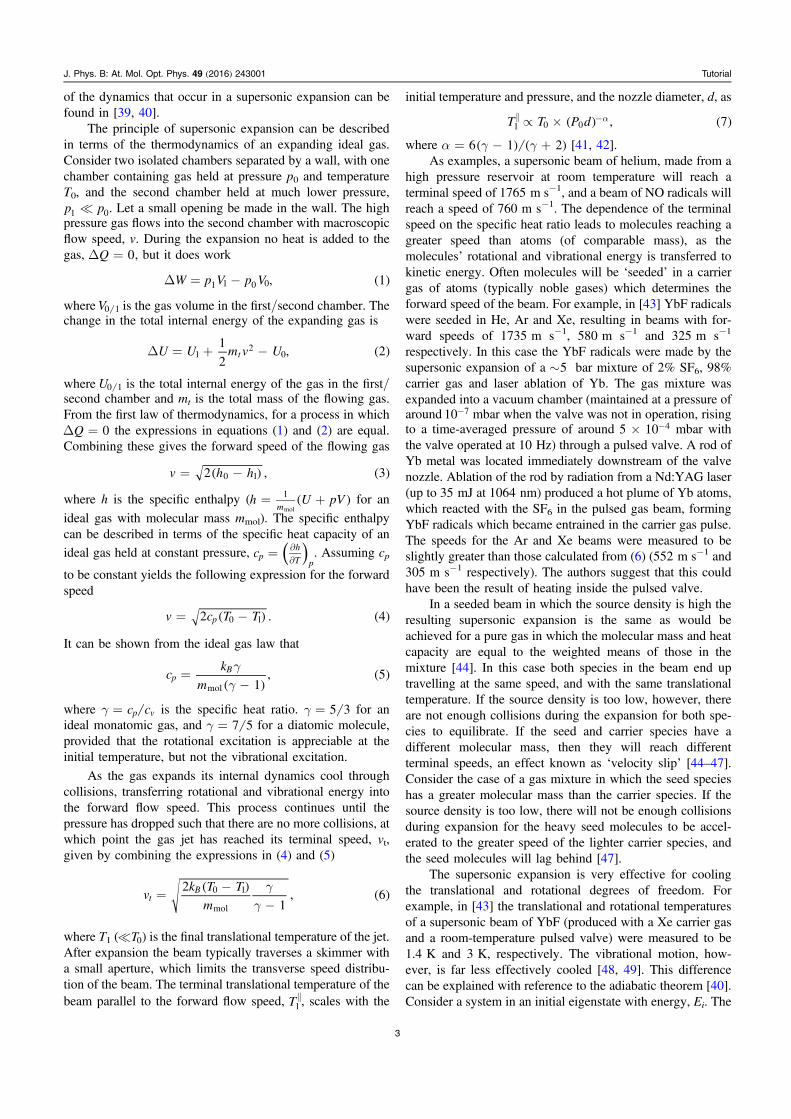