Embed Size (px)
Citation preview
MA
IN M
ENU
OP
TIO
NS
SHIP
’SSTA
TIO
NS
AC
AD
EMY
TR
AIN
ING
AD
VA
NC
EDT
UT
OR
IAL
AP
PEN
DIC
ESQ
UIC
K STA
RT
TU
TO
RIA
L
688(I) Hunter/KillerTM

CreditsWritten by Valerie Hanscom, David Luoto, Terry Jones & Gregory Howard.
Design and Layout by Marco Garcia and Tom Peters.
Sub Illustrations by Adrian Bourne–Liquid Pixels.
Sonalysts Combat Simulations – 688(I) Hunter/Killer and Sonalysts are trademarks or registered trademarks of Sonalysts, Inc.
MA
IN M
ENU
OP
TIO
NS
SHIP
’SSTA
TIO
NS
AC
AD
EMY
TR
AIN
ING
AD
VA
NC
EDT
UT
OR
IAL
AP
PEN
DIC
ESQ
UIC
K STA
RT
TU
TO
RIA
L
How To Use This BookA game as complex as 688(I) Hunter/Killer requires documentation bothdetailed and simple. To that end we have done our best to create the mostcomplete and concise user’s manual, reference card, and install guide possible.
Each chapter of the user’s manual begins with a detailed table of contentsand a chapter summary. Each chapter contains exhaustive information onsubmarine operations, theory, or tactics. We’ve also included a Quick Start,and an Advanced Tutorial to guide you through single mission Number 1.
Hints and Notes like this provide gameplay tips or exceptions to previously mentioned conventions.
guides you through the pre-game menus anddrops you right into the first mission with adetailed, step-by-step introductory walk-through.
describes all available pre-game settings andtheir influence on gameplay. It also describesthe different game modes.
lays out each of the 688(I)’s stations and detailsthe operation of every available function.
covers the principles and theories behind sub-marine operations and tactics.
walks you through Single Mission #1.
1 Chapter 1
Qu
ick Start Tu
torial
MA
IN M
ENU
OP
TIO
NS
SHIP
’S STA
TIO
NS
AC
AD
EMY
TR
AIN
ING
AD
VA
NC
EDT
UT
OR
IAL
AP
PEN
DIC
ESQ
UIC
K STA
RT
TU
TO
RIA
L
Chapter 1 Quick Start Tutorial
Chapter 2 Main Menu/Options
Chapter 3 Ship’s Stations
Chapter 4 Academy Training
Chapter 5 Advanced Tutorial
688(i)/AttackSubChptr1 5/6/98 10:10 AM Page 3
Appendix A Object List lists vessels and aircraft in the game.
Appendix B Acronyms lists military abbreviations.
Appendix C Glossary
Appendix D Bibliography
2 Appendices
MA
IN M
ENU
OP
TIO
NS
SHIP
’SSTA
TIO
NS
AC
AD
EMY
TR
AIN
ING
AD
VA
NC
EDT
UT
OR
IAL
AP
PEN
DIC
ESQ
UIC
K STA
RT
TU
TO
RIA
L
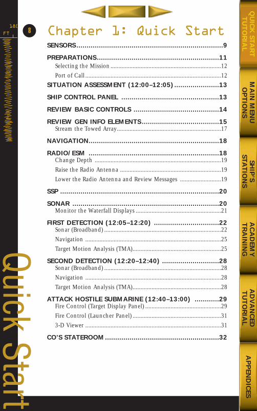
Table of ContentsCHAPTER 1: QUICK START ................................................8
Sensors ....................................................................................................9Preparations ..........................................................................................11
Selecting the Mission ..................................................................12Port of Call ..................................................................................12
Situation Assessment (12:00–12:05) ..................................................13Ship Control Panel ............................................................................13Review Basic Controls ........................................................................14Review Gen Info Elements ...............................................................15
Stream the Towed Array ..............................................................17Navigation ............................................................................................18Radio/ESM ............................................................................................18
Change Depth ............................................................................19Raise the Radio Antenna..............................................................19Lower the Radio Antenna and Review Messages..........................19
SSP ........................................................................................................20Sonar ....................................................................................................20
Monitor the Waterfall Displays ....................................................22First Detection (12:05–12:20) ............................................................22
Sonar (Broadband) ......................................................................22Navigation ..................................................................................25Target Motion Analysis (TMA) ....................................................25
Second Detection (12:20–12:40) ........................................................28Sonar (Broadband) ......................................................................28Navigation ..................................................................................28Target Motion Analysis (TMA) ....................................................28
Attack Hostile Submarine (12:40–13:00)...........................................29Fire Control (Weapons Panel) ......................................................29Fire Control (Launcher Panel) ......................................................313-D Viewer ..................................................................................31
CO’s Stateroom ...................................................................................32
CHAPTER 2: MAIN MENU/OPTIONS ................................35Change of Command Screen ...........................................................36Main Menu .........................................................................................36
Training Mission ..........................................................................36Training Missions ........................................................................37Single Mission ............................................................................37Campaign ..................................................................................39Mission Editor..............................................................................39Mission Editor Hot Keys ..............................................................44Multiplayer ..................................................................................45Captain’s Log ..............................................................................50Ship’s Information Books ............................................................51Info On-Line ...............................................................................51Options ......................................................................................52Exit to Windows ..........................................................................54
In Port .................................................................................................54Weapons Depot ..........................................................................55Repair Yard ..................................................................................56
General Information (Gen Info) Area ..............................................56Control Panel ..............................................................................58
Saving a mission or campaign..........................................................60
3
MA
IN M
ENU
OP
TIO
NS
SHIP
’SSTA
TIO
NS
AC
AD
EMY
TR
AIN
ING
AD
VA
NC
EDT
UT
OR
IAL
AP
PEN
DIC
ESQ
UIC
K STA
RT
TU
TO
RIA
L
CHAPTER 3: SHIP’S STATIONS ..........................................62Ship Control .......................................................................................63Sonar ....................................................................................................65
Broadband ..................................................................................66Narrowband................................................................................68Demodulated Noise (DEMON)....................................................70Active ..........................................................................................72Active Intercept ..........................................................................74
Radar ....................................................................................................75Radio Room/ESM.................................................................................76Target Motion Analysis ......................................................................78
Fire Control: Weapons and Launchers ........................................81Periscope ....................................................................................88Sound Speed Profile ....................................................................90Ship’s Information Books ............................................................91Info On-line.................................................................................92Navigation ..................................................................................93CO’s Stateroom ..........................................................................953-D Control Room ......................................................................973-D Object View..........................................................................98
CHAPTER 4: ACADEMY TRAINING..................................100Ten Mission Phases ..........................................................................102Preparing for the Mission ...............................................................102
Evaluating the Mission Objectives..............................................102Upgrading Your Ship ................................................................102Choosing Your Weapon Loadout ..............................................103
Receiving the Latest Mission Data ................................................104Maneuvering and Navigating ..........................................................104
Buoyancy and Weight ..............................................................104Hydrodynamic Forces ................................................................107Diving ......................................................................................108Surfacing ..................................................................................108Maneuver Hazards ....................................................................109
Maintaining Stealth...........................................................................111Sonar and the Ocean Environment............................................111Use Thermal Layers to Your Advantage......................................114Use Active Sensors ....................................................................114Avoid Cavitating........................................................................114Limit Your Speed ......................................................................115Operate In Your Opponent’s Baffles ..........................................115Avoid Depth Stress ....................................................................116Raise Masts Only When Necessary ............................................116Use Discretion When Attacking ................................................117
Detecting Contacts ...........................................................................117Periscope ..................................................................................118Radar ........................................................................................119ESM ..........................................................................................121Sonar ........................................................................................124688(I) Sensor Comparison Table................................................132
Classifying Contacts .........................................................................136Classification Using Narrowband Sonar ....................................136Classification Using the Periscope ..............................................138
4
MA
IN M
ENU
OP
TIO
NS
SHIP
’SSTA
TIO
NS
AC
AD
EMY
TR
AIN
ING
AD
VA
NC
EDT
UT
OR
IAL
AP
PEN
DIC
ESQ
UIC
K STA
RT
TU
TO
RIA
L
Classification Using ESM............................................................140Classification Using the DEMON................................................140
Targeting Contacts..............................................................................141Targeting With Active Sensors ..................................................141Targeting With Passive Sonar ....................................................142
688(I) Weapon Launchers ..................................................................152688(I) Weapon Types ..........................................................................154Launching Weapons ..........................................................................157Launching Missiles Horizontally........................................................157
Vertical Launch of Missiles ........................................................157ADCAP Torpedo Launch ............................................................157Launching Harpoons ................................................................162Launching Tomahawks ..............................................................165Launching Mines ......................................................................168
Evasive Maneuvers..............................................................................171Torpedo Evasion ........................................................................171
Special Forces Operations ..................................................................173Submerged Lock out Procedure ................................................174Submerged Lock in Procedure ..................................................174Surfaced Launch Procedure ......................................................175Surfaced Recovery Procedure ....................................................176Launching Special Operations Forces ........................................176Recovering Special Operations Forces........................................177
Search and Rescue Operations............................................................177Principles of the Operating Procedure ......................................177Surface Search and Rescue Procedure........................................177DSRV Operations ......................................................................178
Casualty Procedures............................................................................178Flooding Procedure ..................................................................179Emergency Deep ......................................................................179
Mission Profiles ..................................................................................182Anti-Submarine Warfare ............................................................182Anti-Surface Ship Warfare ..........................................................182Strike Warfare ............................................................................183Mine Warfare ............................................................................183Naval Special Warfare................................................................184Surveillance ..............................................................................184
CHAPTER 5: ADVANCED TUTORIAL................................186Prerequisite ........................................................................................186Preparations ........................................................................................188
Selecting the Mission ................................................................190Situation Assessment (12:00–12:05) ..........................................190Radio/ESM ................................................................................191
Practice Target Motion Analysis (12:05–12:20)..................................192Sonar (Broadband) ....................................................................192Navigation ................................................................................195Target Motion Analysis (TMA) ..................................................196Sonar (DEMON) ........................................................................198Target Motion Analysis (TMA) ..................................................200Radar ........................................................................................203Target Motion Analysis (TMA) ..................................................205
Second Detection (12:20–12:40) ........................................................206Change Depth and Course........................................................206
5
MA
IN M
ENU
OP
TIO
NS
SHIP
’S STA
TIO
NS
AC
AD
EMY
TR
AIN
ING
AD
VA
NC
EDT
UT
OR
IAL
AP
PEN
DIC
ESQ
UIC
K STA
RT
TU
TO
RIA
L
688(i)/AttackSubChptr1 5/6/98 10:10 AM Page 7
Sonar (Broadband) ....................................................................206Target Motion Analysis (TMA) ..................................................208Navigation ................................................................................210Sonar (DEMON) ........................................................................210Target Motion Analysis (TMA) ..................................................212
Attack Hostile Submarine (12:40–13:00).........................................213Fire Control (Target Display Panel) ............................................213Fire Control (Launcher Panel) ....................................................2153-D Viewer ................................................................................216
Search For Krivak (12:40–13:05) .....................................................218Increase Speed and Go To Periscope Depth ..............................218Radio/ESM ................................................................................218Target Motion Analysis (TMA) ..................................................219Navigation ................................................................................220Target Motion Analysis (TMA) ..................................................222Change Depth, Course, and Speed To Close Range ..................223Navigation ................................................................................223
Prepare Attack On Krivak (13:05–13:25)........................................223Change Depth and Speed ........................................................223Radio/ESM ................................................................................223Change Depth, Course, and Speed To Close Range ..................224Sonar (Broadband) ....................................................................224
Attack Krivak (13:25–13:50) ............................................................225Fire Control (Weapons Panel) ....................................................225Fire Control (Launcher Panel) ....................................................2263-D Viewer ................................................................................227Sonar (Broadband) ....................................................................227Change Course and Speed ........................................................227Target Motion Analysis (TMA) ..................................................227Navigation ................................................................................228Change Speed and Depth ........................................................228Periscope ..................................................................................228Fire Control (Launcher Panel) ....................................................228Fire Control (Target Display Panel) ............................................230Fire Control (Launcher Panel) ....................................................2303-D Viewer or Periscope ............................................................231
Attack Cuban Armory (13:50–14:15) .............................................232Radio/ESM ................................................................................232Fire Control (Weapons Panel) ....................................................232Fire Control (Launcher Panel) ....................................................2333-D Viewer or Fire Control (Weapons Panel)..............................233Radio/ESM ................................................................................234
APPENDIX A..............................................................236APPENDIX B ..............................................................240APPENDIX C ..............................................................244APPENDIX D..............................................................248
6
MA
IN M
ENU
OP
TIO
NS
SHIP
’SSTA
TIO
NS
AC
AD
EMY
TR
AIN
ING
AD
VA
NC
EDT
UT
OR
IAL
AP
PEN
DIC
ESQ
UIC
K STA
RT
TU
TO
RIA
L
MA
IN M
ENU
OP
TIO
NS
SHIP
’S STA
TIO
NS
AC
AD
EMY
TR
AIN
ING
AD
VA
NC
EDT
UT
OR
IAL
AP
PEN
DIC
ESQ
UIC
K STA
RT
TU
TO
RIA
L
688(i)/AttackSubChptr1 5/6/98 10:10 AM Page 9
Chapter 1: Quick StartSENSORS ........................................................................9
PREPARATIONS............................................................11Selecting the Mission......................................................................12Port of Call ......................................................................................12
SITUATION ASSESSMENT (12:00–12:05)......................13
SHIP CONTROL PANEL ................................................13
REVIEW BASIC CONTROLS ..........................................14
REVIEW GEN INFO ELEMENTS ......................................15Stream the Towed Array..................................................................17
NAVIGATION................................................................18
RADIO/ESM ................................................................18Change Depth ................................................................................19Raise the Radio Antenna ................................................................19Lower the Radio Antenna and Review Messages ..........................19
SSP ..............................................................................20
SONAR ........................................................................20Monitor the Waterfall Displays ......................................................21
FIRST DETECTION (12:05–12:20) ................................22Sonar (Broadband) ..........................................................................22Navigation ......................................................................................25Target Motion Analysis (TMA)........................................................25
SECOND DETECTION (12:20–12:40) ............................28Sonar (Broadband) ..........................................................................28Navigation ......................................................................................28Target Motion Analysis (TMA)........................................................28
ATTACK HOSTILE SUBMARINE (12:40–13:00) ............29Fire Control (Target Display Panel) ................................................29Fire Control (Launcher Panel) ........................................................313-D Viewer ......................................................................................31
CO’S STATEROOM........................................................32
8FT
180
Quick Start
MA
IN M
ENU
OP
TIO
NS
SHIP
’S STA
TIO
NS
AC
AD
EMY
TR
AIN
ING
AD
VA
NC
EDT
UT
OR
IAL
AP
PEN
DIC
ESQ
UIC
K STA
RT
TU
TO
RIA
L
688(i)/AttackSubChptr1 5/6/98 10:10 AM Page 10
MA
IN M
ENU
OP
TIO
NS
SHIP
’S STA
TIO
NS
AC
AD
EMY
TR
AIN
ING
AD
VA
NC
EDT
UT
OR
IAL
AP
PEN
DIC
ESQ
UIC
K STA
RT
TU
TO
RIA
L
The Quickstart Tutorial is designed to introduce inexperienced 688(I) Hunter/Killer
players to the essentials of submarine warfare. Following the instructions in this
chapter, you’ll learn how to detect, classify, and attack a submarine.
Before beginning, take a minute to familiarize yourself with the various sensors
aboard the 688(I).
Sensors
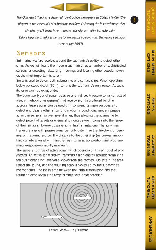
Submarine warfare revolves around the submarine’s ability to detect otherships. As you will learn, the modern submarine has a number of sophisticatedsensors for detecting, classifying, tracking, and locating other vessels; howev-er, the most important is sonar.Sonar is used to detect both submarines and surface ships. When operatingbelow periscope depth (60 ft), sonar is the submarine’s only sensor. As such,its value can’t be exaggerated. There are two types of sonar: passive and active. A passive sonar consists ofa set of hydrophones (sensors) that receive sounds produced by othersources. Passive sonar can be used only to listen. Its major purpose is todetect and classify other ships. Under optimal conditions, modern passivesonar can sense ships over several miles, thus allowing the submarine todetect potential targets or enemy ships long before it comes into the rangeof their sensors. However, passive sonar has its limitations. The sonarmantracking a ship with passive sonar can only determine the direction, or bear-ing, of the sound source. The distance to the other ship (range)—an impor-tant consideration when maneuvering into an attack position and program-ming weapons—is initially unknown.The same is not true of active sonar, which operates on the principal of echoranging. An active sonar system transmits a high-energy acoustic signal (thefamous “sonar ping” everyone knows from the movies). Objects in the areareflect the sound, and the resulting echo is picked up by the submarine’shydrophones. The lag in time between the initial transmission and thereturning echo reveals the target’s range with great precision.
9
Passive Sonar— Sub just listens.
688(i)/AttackSubChptr1 5/6/98 10:10 AM Page 11
FT
180
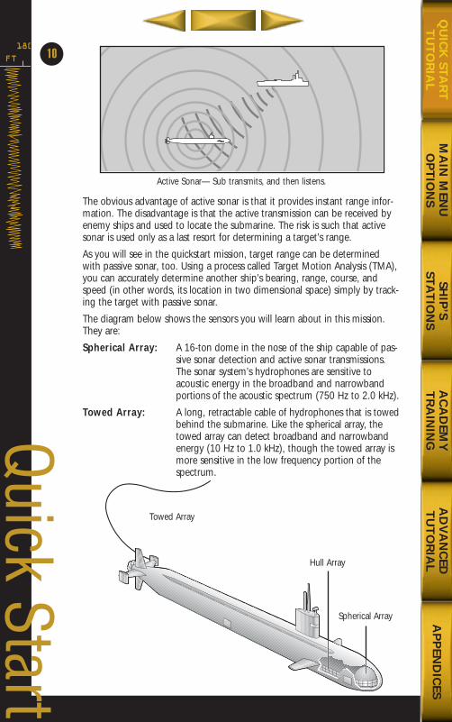
The obvious advantage of active sonar is that it provides instant range infor-mation. The disadvantage is that the active transmission can be received byenemy ships and used to locate the submarine. The risk is such that activesonar is used only as a last resort for determining a target’s range.
As you will see in the quickstart mission, target range can be determinedwith passive sonar, too. Using a process called Target Motion Analysis (TMA),you can accurately determine another ship’s bearing, range, course, andspeed (in other words, its location in two dimensional space) simply by track-ing the target with passive sonar.
The diagram below shows the sensors you will learn about in this mission.They are:
Spherical Array: A 16-ton dome in the nose of the ship capable of pas-sive sonar detection and active sonar transmissions.The sonar system’s hydrophones are sensitive toacoustic energy in the broadband and narrowbandportions of the acoustic spectrum (750 Hz to 2.0 kHz).
Towed Array: A long, retractable cable of hydrophones that is towedbehind the submarine. Like the spherical array, thetowed array can detect broadband and narrowbandenergy (10 Hz to 1.0 kHz), though the towed array ismore sensitive in the low frequency portion of thespectrum.
10
Quick Start
MA
IN M
ENU
OP
TIO
NS
SHIP
’S STA
TIO
NS
AC
AD
EMY
TR
AIN
ING
AD
VA
NC
EDT
UT
OR
IAL
AP
PEN
DIC
ESQ
UIC
K STA
RT
TU
TO
RIA
L
Towed Array
Spherical Array
Hull Array
Active Sonar— Sub transmits, and then listens.
688(i)/AttackSubChptr1 5/6/98 10:10 AM Page 12
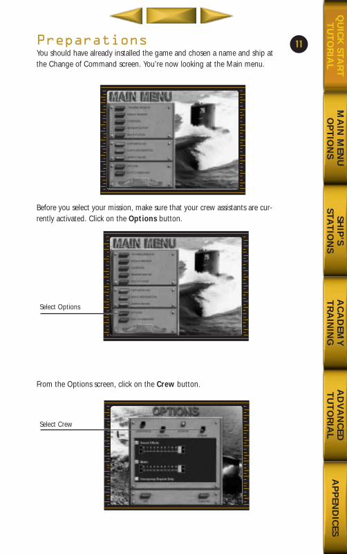
PreparationsYou should have already installed the game and chosen a name and ship atthe Change of Command screen. You’re now looking at the Main menu.
Before you select your mission, make sure that your crew assistants are cur-rently activated. Click on the Options button.
From the Options screen, click on the Crew button.
11
MA
IN M
ENU
OP
TIO
NS
SHIP
’S STA
TIO
NS
AC
AD
EMY
TR
AIN
ING
AD
VA
NC
EDT
UT
OR
IAL
AP
PEN
DIC
ESQ
UIC
K STA
RT
TU
TO
RIA
L
Select Options
Select Crew
688(i)/AttackSubChptr1 5/6/98 10:10 AM Page 13
FT
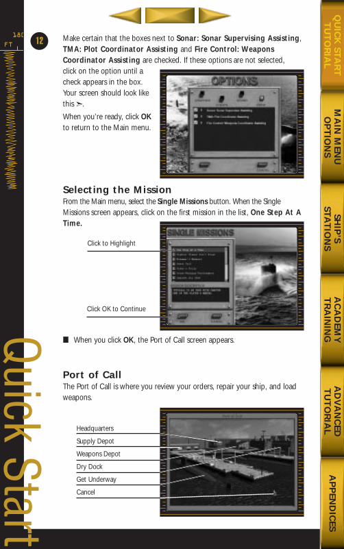
180 Make certain that the boxes next to Sonar: Sonar Supervising Assisting,TMA: Plot Coordinator Assisting and Fire Control: WeaponsCoordinator Assisting are checked. If these options are not selected, click on the option until acheck appears in the box.Your screen should look likethis ➣.
When you’re ready, click OKto return to the Main menu.
Selecting the MissionFrom the Main menu, select the Single Missions button. When the SingleMissions screen appears, click on the first mission in the list, One Step At ATime.
■ When you click OK, the Port of Call screen appears.
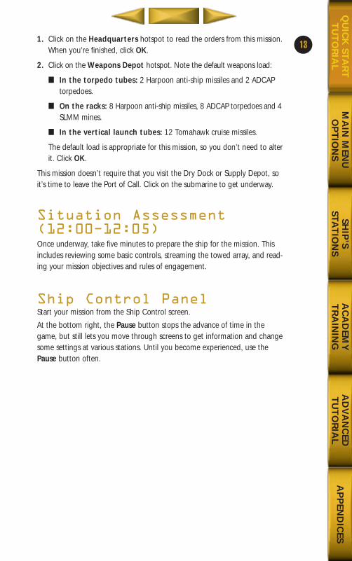
Port of CallThe Port of Call is where you review your orders, repair your ship, and loadweapons.
12
Click OK to Continue
Click to Highlight
Headquarters
Supply Depot
Weapons Depot
Dry Dock
Get Underway
Cancel
Quick Start
MA
IN M
ENU
OP
TIO
NS
SHIP
’S STA
TIO
NS
AC
AD
EMY
TR
AIN
ING
AD
VA
NC
EDT
UT
OR
IAL
AP
PEN
DIC
ESQ
UIC
K STA
RT
TU
TO
RIA
L
688(i)/AttackSubChptr1 5/6/98 10:10 AM Page 14
1. Click on the Headquarters hotspot to read the orders from this mission.When you’re finished, click OK.
2. Click on the Weapons Depot hotspot. Note the default weapons load:
■ In the torpedo tubes: 2 Harpoon anti-ship missiles and 2 ADCAPtorpedoes.
■ On the racks: 8 Harpoon anti-ship missiles, 8 ADCAP torpedoes and 4SLMM mines.
■ In the vertical launch tubes: 12 Tomahawk cruise missiles.
The default load is appropriate for this mission, so you don’t need to alterit. Click OK.
This mission doesn’t require that you visit the Dry Dock or Supply Depot, soit’s time to leave the Port of Call. Click on the submarine to get underway.
Situation Assessment(12:00Ð12:05)Once underway, take five minutes to prepare the ship for the mission. Thisincludes reviewing some basic controls, streaming the towed array, and read-ing your mission objectives and rules of engagement.
Ship Control PanelStart your mission from the Ship Control screen.
At the bottom right, the Pause button stops the advance of time in thegame, but still lets you move through screens to get information and changesome settings at various stations. Until you become experienced, use thePause button often.
13
MA
IN M
ENU
OP
TIO
NS
SHIP
’S STA
TIO
NS
AC
AD
EMY
TR
AIN
ING
AD
VA
NC
EDT
UT
OR
IAL
AP
PEN
DIC
ESQ
UIC
K STA
RT
TU
TO
RIA
L
688(i)/AttackSubChptr1 5/6/98 10:10 AM Page 15
FT
180
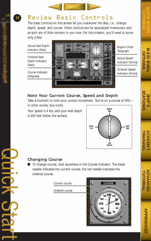
Review Basic ControlsThe basic controls on this screen let you maneuver the ship, i.e., changedepth, speed, and course. Other controls are for specialized maneuvers, andas such are of little concern to you now. For this mission, you’ll need to knowonly a few:
Note Your Current Course, Speed and DepthTake a moment to note your current movement. You’re on a course of 000—in other words, due north.
Your speed is 4 kts, and your keel depthis 350 feet below the surface.
Changing Course■ To change course, click anywhere in the Course Indicator. The black
needle indicates the current course; the red needle indicates theordered course.
14
Current course
Ordered course
WEST270
EAST090
180SOUTH
NORTH000
Actual Keel DepthIndicator (Feet)
Ordered KeelDepth Indicator(Feet)
Course Indicator(Degrees)
Engine OrderTelegraph
Actual SpeedIndicator (Knots)
Ordered SpeedIndicator (Knots)
Quick Start
MA
IN M
ENU
OP
TIO
NS
SHIP
’S STA
TIO
NS
AC
AD
EMY
TR
AIN
ING
AD
VA
NC
EDT
UT
OR
IAL
AP
PEN
DIC
ESQ
UIC
K STA
RT
TU
TO
RIA
L
688(i)/AttackSubChptr1 5/6/98 10:10 AM Page 16
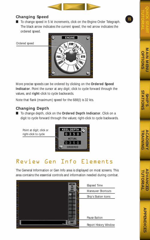
Changing Speed■ To change speed in 5 kt increments, click on the Engine Order Telegraph.
The black arrow indicates the current speed; the red arrow indicates theordered speed.
More precise speeds can be ordered by clicking on the Ordered SpeedIndicator. Point the cursor at any digit; click to cycle forward through thevalues, and right-click to cycle backwards.
Note that flank (maximum) speed for the 688(I) is 32 kts.
Changing Depth■ To change depth, click on the Ordered Depth Indicator. Click on a
digit to cycle forward through the values; right-click to cycle backwards.
Review Gen Info Elements
The General Information or Gen Info area is displayed on most screens. Thisarea contains the essential controls and information needed during combat.
15
MA
IN M
ENU
OP
TIO
NS
SHIP
’S STA
TIO
NS
AC
AD
EMY
TR
AIN
ING
AD
VA
NC
EDT
UT
OR
IAL
AP
PEN
DIC
ESQ
UIC
K STA
RT
TU
TO
RIA
L
Ordered speed
Point at digit; click orright-click to cycle
Elapsed Time
Maneuver Shortcuts
Ship’s Station Icons
Pause Button
Report History Window
688(i)/AttackSubChptr1 5/6/98 10:10 AM Page 17
FT
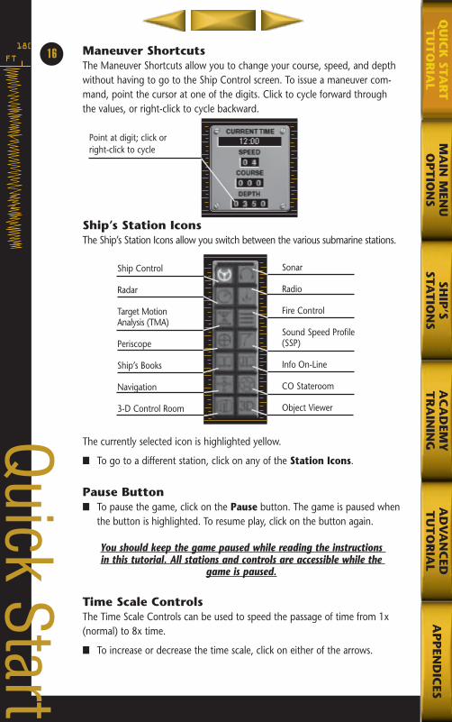
180 Maneuver ShortcutsThe Maneuver Shortcuts allow you to change your course, speed, and depthwithout having to go to the Ship Control screen. To issue a maneuver com-mand, point the cursor at one of the digits. Click to cycle forward throughthe values, or right-click to cycle backward.
Ship’s Station IconsThe Ship’s Station Icons allow you switch between the various submarine stations.
The currently selected icon is highlighted yellow.
■ To go to a different station, click on any of the Station Icons.
Pause Button■ To pause the game, click on the Pause button. The game is paused when
the button is highlighted. To resume play, click on the button again.
You should keep the game paused while reading the instructions in this tutorial. All stations and controls are accessible while the
game is paused.
Time Scale ControlsThe Time Scale Controls can be used to speed the passage of time from 1x(normal) to 8x time.
■ To increase or decrease the time scale, click on either of the arrows.
16
Ship Control
Radar
Target Motion Analysis (TMA)
Periscope
Ship’s Books
Navigation
3-D Control Room
Sonar
Radio
Fire Control
Sound Speed Profile(SSP)
Info On-Line
CO Stateroom
Object ViewerQuick Start
Point at digit; click orright-click to cycle
MA
IN M
ENU
OP
TIO
NS
SHIP
’SSTA
TIO
NS
AC
AD
EMY
TR
AIN
ING
AD
VA
NC
EDT
UT
OR
IAL
AP
PEN
DIC
ESQ
UIC
K STA
RT
TU
TO
RIA
L
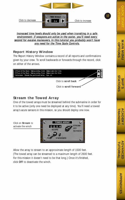
Increased time levels should only be used when transiting in a safe environment- if weapons are active in the water, you’ll need every
second for evasive maneuvers. In this tutorial you probably won’t haveany need for the Time Scale Controls.
Report History WindowThe Report History Window contains a record of all reports and confirmationsgiven by your crew. To scroll backwards or forwards through the record, clickon either of the arrows.
Stream the Towed ArrayOne of the towed arrays must be streamed behind the submarine in order forit to be active (only one need be deployed at any time). You’ll need a towedarray’s acute sensors in this mission, so you should deploy one now.
Allow the array to stream to an approximate length of 1500 feet. (The towed array can be streamed to a maximum length of 2600 feet. For this mission it doesn’t need to be that long.) Once it’s finished, click Off to deactivate the winch.
17
MA
IN M
ENU
OP
TIO
NS
SHIP
’S STA
TIO
NS
AC
AD
EMY
TR
AIN
ING
AD
VA
NC
EDT
UT
OR
IAL
AP
PEN
DIC
ESQ
UIC
K STA
RT
TU
TO
RIA
LClick to increaseClick to decrease
Click to scroll forward
Click to scroll back
Click on Stream to activate the winch
688(i)/AttackSubChptr1 5/6/98 10:11 AM Page 19
FT
180
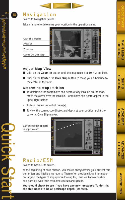
NavigationSwitch to Navigation screen.
Take a minute to determine your location in the operations area.
Adjust Map View■ Click on the Zoom In button until the map scale is at 10 NM per inch.
■ Click on the Center On Own Ship button to move your submarine tothe center of the view.
Determine Map Position■ To determine the coordinates and depth of any location on the map,
move the cursor over the location. Coordinates and depth appear in theupper right corner.
• To turn this feature on/off press X.
■ To view the current coordinates and depth at your position, point thecursor at Own Ship marker.
Radio/ESMSwitch to Radio/ESM screen.
At the beginning of each mission, you should always review your current mis-sion orders and intelligence reports. These often provide critical informationon targets: the types of ships you’re looking for, their last known position,and possibly even their estimated courses and speeds.
You should check to see if you have any new messages. To do this,the ship needs to be at periscope depth (60 feet).
18
Quick Start
Own Ship Marker
Zoom in
Zoom out
Center On Own Ship
Current position appearsin upper corner
MA
IN M
ENU
OP
TIO
NS
SHIP
’S STA
TIO
NS
AC
AD
EMY
TR
AIN
ING
AD
VA
NC
EDT
UT
OR
IAL
AP
PEN
DIC
ESQ
UIC
K STA
RT
TU
TO
RIA
L
688(i)/AttackSubChptr1 5/6/98 10:11 AM Page 20
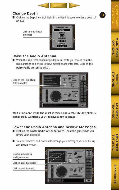
Change Depth■ Click on the Depth control digits in the Gen Info area to order a depth of
60 feet.
Raise the Radio Antenna■ When the ship reaches periscope depth (60 feet), you should raise the
radio antenna and check for new messages and intel data. Click on theRaise Radio Antenna switch.
Wait a moment while the mast is raised and a satellite downlink isestablished. Eventually you’ll receive a new message.
Lower the Radio Antenna and Review Messages■ Click on the Lower Radio Antenna switch. Pause the game while you
review your messages.
■ To scroll forwards and backwards through your messages, click on the upand down arrows.
19
MA
IN M
ENU
OP
TIO
NS
SHIP
’S STA
TIO
NS
AC
AD
EMY
TR
AIN
ING
AD
VA
NC
EDT
UT
OR
IAL
AP
PEN
DIC
ESQ
UIC
K STA
RT
TU
TO
RIA
L
Click to order depth of 60 feet
Click on the Raise RadioAntenna switch
Incoming messages/intelligence data
Click to scroll backwards
Click to scroll forwards
688(i)/AttackSubChptr1 5/6/98 10:11 AM Page 21
FT
180
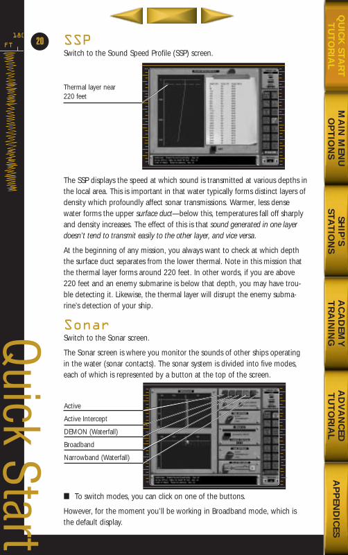
SSPSwitch to the Sound Speed Profile (SSP) screen.
The SSP displays the speed at which sound is transmitted at various depths inthe local area. This is important in that water typically forms distinct layers ofdensity which profoundly affect sonar transmissions. Warmer, less densewater forms the upper surface duct—below this, temperatures fall off sharplyand density increases. The effect of this is that sound generated in one layerdoesn’t tend to transmit easily to the other layer, and vice versa.
At the beginning of any mission, you always want to check at which depththe surface duct separates from the lower thermal. Note in this mission thatthe thermal layer forms around 220 feet. In other words, if you are above220 feet and an enemy submarine is below that depth, you may have trou-ble detecting it. Likewise, the thermal layer will disrupt the enemy subma-rine’s detection of your ship.
SonarSwitch to the Sonar screen.
The Sonar screen is where you monitor the sounds of other ships operatingin the water (sonar contacts). The sonar system is divided into five modes,each of which is represented by a button at the top of the screen.
■ To switch modes, you can click on one of the buttons.
However, for the moment you’ll be working in Broadband mode, which isthe default display.
20
Active
Active Intercept
DEMON (Waterfall)
Broadband
Narrowband (Waterfall)
Quick Start
Thermal layer near 220 feet
MA
IN M
ENU
OP
TIO
NS
SHIP
’S STA
TIO
NS
AC
AD
EMY
TR
AIN
ING
AD
VA
NC
EDT
UT
OR
IAL
AP
PEN
DIC
ESQ
UIC
K STA
RT
TU
TO
RIA
L
688(i)/AttackSubChptr1 5/6/98 10:11 AM Page 22
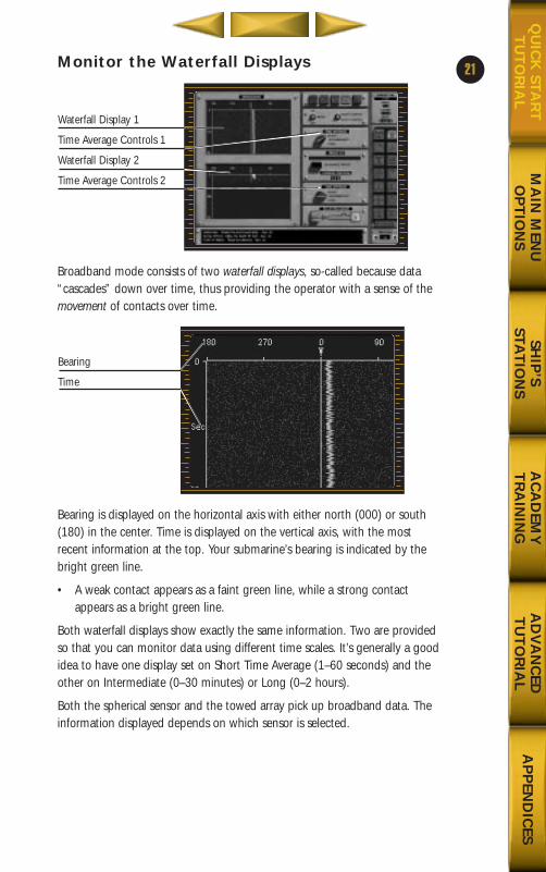
Monitor the Waterfall Displays
Broadband mode consists of two waterfall displays, so-called because data“cascades” down over time, thus providing the operator with a sense of themovement of contacts over time.
Bearing is displayed on the horizontal axis with either north (000) or south(180) in the center. Time is displayed on the vertical axis, with the mostrecent information at the top. Your submarine’s bearing is indicated by thebright green line.
• A weak contact appears as a faint green line, while a strong contactappears as a bright green line.
Both waterfall displays show exactly the same information. Two are providedso that you can monitor data using different time scales. It’s generally a goodidea to have one display set on Short Time Average (1–60 seconds) and theother on Intermediate (0–30 minutes) or Long (0–2 hours).
Both the spherical sensor and the towed array pick up broadband data. Theinformation displayed depends on which sensor is selected.
21
MA
IN M
ENU
OP
TIO
NS
SHIP
’S STA
TIO
NS
AC
AD
EMY
TR
AIN
ING
AD
VA
NC
EDT
UT
OR
IAL
AP
PEN
DIC
ESQ
UIC
K STA
RT
TU
TO
RIA
L
Waterfall Display 1
Time Average Controls 1
Waterfall Display 2
Time Average Controls 2
Bearing
Time
688(i)/AttackSubChptr1 5/6/98 10:11 AM Page 23
FT
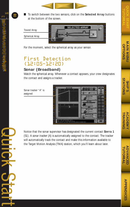
180 ■ To switch between the two sensors, click on the Selected Array buttonsat the bottom of the screen.
For the moment, select the spherical array as your sensor.
First Detection (12:05Ð12:20)Sonar (Broadband)Watch the spherical array. Whenever a contact appears, your crew designatesthe contact and assigns a tracker.
Notice that the sonar supervisor has designated the current contact Sierra 1(S1). A sonar tracker (A) is automatically assigned to the contact. The trackerwill automatically track the contact and make this information available tothe Target Motion Analysis (TMA) station, which you’ll learn about later.
22
Sonar tracker “A” isassigned
Quick Start
Towed Array
Spherical Array
MA
IN M
ENU
OP
TIO
NS
SHIP
’S STA
TIO
NS
AC
AD
EMY
TR
AIN
ING
AD
VA
NC
EDT
UT
OR
IAL
AP
PEN
DIC
ESQ
UIC
K STA
RT
TU
TO
RIA
L
688(i)/AttackSubChptr1 5/6/98 10:11 AM Page 24
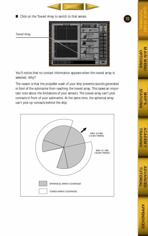
■ Click on the Towed Array to switch to that sensor.
You’ll notice that no contact information appears when the towed array isselected. Why?
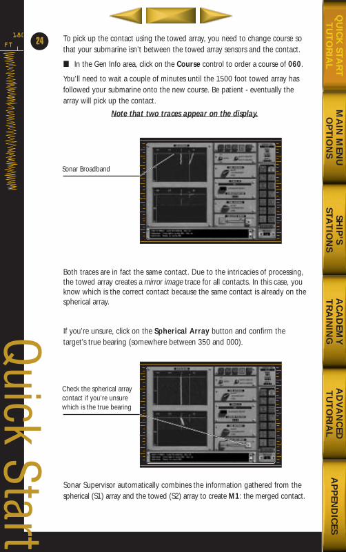
The reason is that the propeller wash of your ship prevents sounds generatedin front of the submarine from reaching the towed array. This raises an impor-tant note about the limitations of your sensors. The towed array can’t pickcontacts in front of your submarine. At the same time, the spherical arraycan’t pick up contacts behind the ship.
23
MA
IN M
ENU
OP
TIO
NS
SHIP
’S STA
TIO
NS
AC
AD
EMY
TR
AIN
ING
AD
VA
NC
EDT
UT
OR
IAL
AP
PEN
DIC
ESQ
UIC
K STA
RT
TU
TO
RIA
L
Towed Array
MAX. 6.9 NM(14,000 YARDS)
MAX. 9.1 NM(18,500 YARDS)
SPHERICAL ARRAY COVERAGE
TOWED ARRAY COVERAGE
688(i)/AttackSubChptr1 5/6/98 10:11 AM Page 25
FT
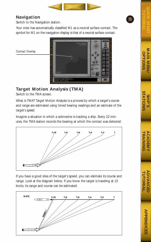
180 To pick up the contact using the towed array, you need to change course sothat your submarine isn’t between the towed array sensors and the contact.
■ In the Gen Info area, click on the Course control to order a course of 060.
You’ll need to wait a couple of minutes until the 1500 foot towed array hasfollowed your submarine onto the new course. Be patient - eventually thearray will pick up the contact.
Note that two traces appear on the display.
Both traces are in fact the same contact. Due to the intricacies of processing,the towed array creates a mirror image trace for all contacts. In this case, youknow which is the correct contact because the same contact is already on thespherical array.
If you’re unsure, click on the Spherical Array button and confirm the target’s true bearing (somewhere between 350 and 000).
Sonar Supervisor automatically combines the information gathered from thespherical (S1) array and the towed (S2) array to create M1: the merged contact.
24
Sonar Broadband
Check the spherical arraycontact if you’re unsurewhich is the true bearing
Quick Start
MA
IN M
ENU
OP
TIO
NS
SHIP
’S STA
TIO
NS
AC
AD
EMY
TR
AIN
ING
AD
VA
NC
EDT
UT
OR
IAL
AP
PEN
DIC
ESQ
UIC
K STA
RT
TU
TO
RIA
L
688(i)/AttackSubChptr1 5/6/98 10:11 AM Page 26
NavigationSwitch to the Navigation station.
Your crew has automatically classified M1 as a neutral surface contact. Thesymbol for M1 on the navigation display is that of a neutral surface contact.
Target Motion Analysis (TMA)Switch to the TMA screen.
What is TMA? Target Motion Analysis is a process by which a target’s courseand range are estimated using timed bearing readings and an estimate of thetarget’s speed.
Imagine a situation in which a submarine is tracking a ship. Every 10 min-utes, the TMA station records the bearing at which the contact was detected:
If you have a good idea of the target’s speed, you can estimate its course andrange. Look at the diagram below. If you know the target is traveling at 10knots, its range and course can be estimated.
25
MA
IN M
ENU
OP
TIO
NS
SHIP
’S STA
TIO
NS
AC
AD
EMY
TR
AIN
ING
AD
VA
NC
EDT
UT
OR
IAL
AP
PEN
DIC
ESQ
UIC
K STA
RT
TU
TO
RIA
L
Contact Overlay
T+10 T+8 T+6 T+4 T+2 T
RANG
E 1
T+10 T+8 T+610 KTS T+4 T+2 T
688(i)/AttackSubChptr1 5/6/98 10:11 AM Page 27
FT
180 The accuracy of the speed estimate is critical. If the target in our examplewas actually traveling at 5 knots, its range would be reduced by half.
The trick is to have a good estimate of the target’s speed. Fortunately foryou, you have a TMA assistant who can not only estimate a target’s speedwith a fair amount of accuracy, he can use that information to derive esti-mates for range and course.
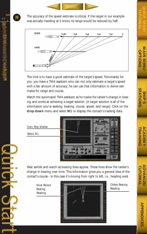
Watch the automated TMA assistant as he tracks the tanker’s change in bear-ing and works at achieving a target solution. (A target solution is all of theinformation you’re seeking: bearing, course, speed, and range). Click on thedrop-down menu and select M1 to display the contact’s tracking data.
Wait awhile and watch as bearing lines appear. These lines show the tanker’schange in bearing over time. This information gives you a general idea of thecontact’s course - in this case it’s moving from right to left, i.e., heading west.
26
Own Ship Marker
Select M1Quick Start
RANG
E 2
T+10 T+8 T+6
5 KTS
10 KTS T+4 T+2 T
Most RecentBearingReading
Oldest BearingReading
MA
IN M
ENU
OP
TIO
NS
SHIP
’S STA
TIO
NS
AC
AD
EMY
TR
AIN
ING
AD
VA
NC
EDT
UT
OR
IAL
AP
PEN
DIC
ESQ
UIC
K STA
RT
TU
TO
RIA
L
688(i)/AttackSubChptr1 5/6/98 10:11 AM Page 28
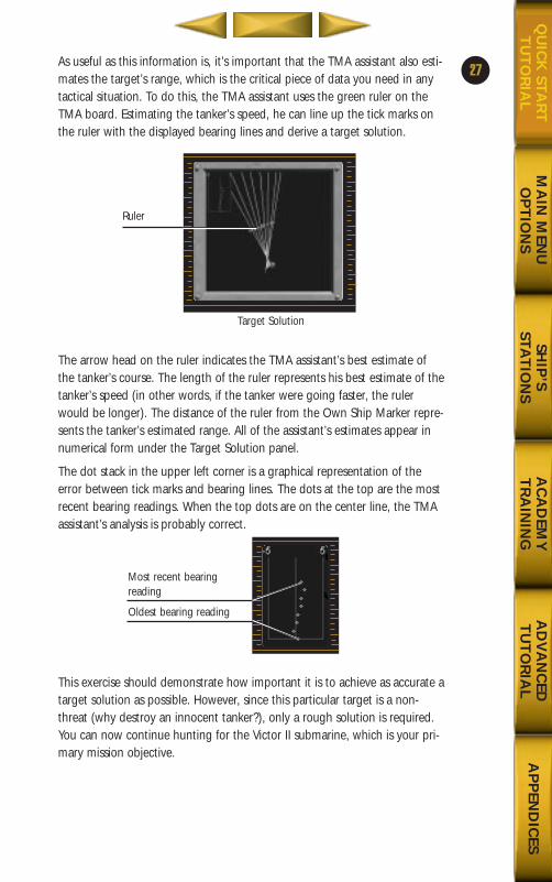
As useful as this information is, it’s important that the TMA assistant also esti-mates the target’s range, which is the critical piece of data you need in anytactical situation. To do this, the TMA assistant uses the green ruler on theTMA board. Estimating the tanker’s speed, he can line up the tick marks onthe ruler with the displayed bearing lines and derive a target solution.
The arrow head on the ruler indicates the TMA assistant’s best estimate ofthe tanker’s course. The length of the ruler represents his best estimate of thetanker’s speed (in other words, if the tanker were going faster, the rulerwould be longer). The distance of the ruler from the Own Ship Marker repre-sents the tanker’s estimated range. All of the assistant’s estimates appear innumerical form under the Target Solution panel.
The dot stack in the upper left corner is a graphical representation of theerror between tick marks and bearing lines. The dots at the top are the mostrecent bearing readings. When the top dots are on the center line, the TMAassistant’s analysis is probably correct.
This exercise should demonstrate how important it is to achieve as accurate atarget solution as possible. However, since this particular target is a non-threat (why destroy an innocent tanker?), only a rough solution is required.You can now continue hunting for the Victor II submarine, which is your pri-mary mission objective.
27
MA
IN M
ENU
OP
TIO
NS
SHIP
’S STA
TIO
NS
AC
AD
EMY
TR
AIN
ING
AD
VA
NC
EDT
UT
OR
IAL
AP
PEN
DIC
ESQ
UIC
K STA
RT
TU
TO
RIA
L
Ruler
Most recent bearingreading
Oldest bearing reading
Target Solution
688(i)/AttackSubChptr1 5/6/98 10:11 AM Page 29
FT
180
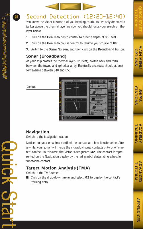
Second Detection (12:20Ð12:40)You know the Victor II is north of you heading south. You’ve only detected atanker above the thermal layer, so now you should focus your search on thelayer below.
1. Click on the Gen Info depth control to order a depth of 350 feet.
2. Click on the Gen Info course control to resume your course of 000.
3. Switch to the Sonar Screen, and then click on the Broadband button.
Sonar (Broadband)As your ship crosses the thermal layer (220 feet), switch back and forthbetween the towed and spherical array. Eventually a contact should appearsomewhere between 040 and 050.
NavigationSwitch to the Navigation station.
Notice that your crew has classified the contact as a hostile submarine. Aftera while, your sonar will merge the individual sonar contacts onto one “mas-ter” contact. In this case, the Victor is designated M2. The contact is repre-sented on the Navigation display by the red symbol designating a hostilesubmarine contact.
Target Motion Analysis (TMA)Switch to the TMA screen.■ Click on the drop-down menu and select M2 to display the contact’s
tracking data.
28
Contact
Quick Start
MA
IN M
ENU
OP
TIO
NS
SHIP
’S STA
TIO
NS
AC
AD
EMY
TR
AIN
ING
AD
VA
NC
EDT
UT
OR
IAL
AP
PEN
DIC
ESQ
UIC
K STA
RT
TU
TO
RIA
L
688(i)/AttackSubChptr1 5/6/98 10:11 AM Page 30
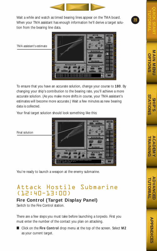
Wait a while and watch as timed bearing lines appear on the TMA board.When your TMA assistant has enough information he’ll derive a target solu-tion from the bearing line data.
To ensure that you have an accurate solution, change your course to 180. Bychanging your ship’s contribution to the bearing rate, you’ll achieve a moreaccurate solution. (As you make more shifts in course, your TMA assistant’sestimates will become more accurate.) Wait a few minutes as new bearingdata is collected.
Your final target solution should look something like this:
You’re ready to launch a weapon at the enemy submarine.
Attack Hostile Submarine(12:40Ð13:00)Fire Control (Target Display Panel)Switch to the Fire Control station.
There are a few steps you must take before launching a torpedo. First youmust enter the number of the contact you plan on attacking.
■ Click on the Fire Control drop menu at the top of the screen. Select M2as your current target.
29
MA
IN M
ENU
OP
TIO
NS
SHIP
’S STA
TIO
NS
AC
AD
EMY
TR
AIN
ING
AD
VA
NC
EDT
UT
OR
IAL
AP
PEN
DIC
ESQ
UIC
K STA
RT
TU
TO
RIA
L
TMA assistant’s estimate
Final solution
688(i)/AttackSubChptr1 5/6/98 10:11 AM Page 31
FT
180
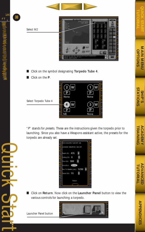
■ Click on the symbol designating Torpedo Tube 4.
■ Click on the P.
“P” stands for presets. These are the instructions given the torpedo prior tolaunching. Since you also have a Weapons assistant active, the presets for thetorpedo are already set.
■ Click on Return. Now click on the Launcher Panel button to view thevarious controls for launching a torpedo.
30
Quick Start
Select M2
Select Torpedo Tube 4
Launcher Panel button
MA
IN M
ENU
OP
TIO
NS
SHIP
’S STA
TIO
NS
AC
AD
EMY
TR
AIN
ING
AD
VA
NC
EDT
UT
OR
IAL
AP
PEN
DIC
ESQ
UIC
K STA
RT
TU
TO
RIA
L
688(i)/AttackSubChptr1 5/6/98 10:11 AM Page 32
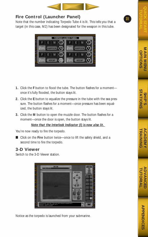
Fire Control (Launcher Panel)Note that the number indicating Torpedo Tube 4 is lit. This tells you that atarget (in this case, M2) has been designated for the weapon in this tube.
1. Click the F button to flood the tube. The button flashes for a moment—once it’s fully flooded, the button stays lit.
2. Click the E button to equalize the pressure in the tube with the sea pres-sure. The button flashes for a moment—once pressure has been equal-ized, the button stays lit.
3. Click the M button to open the muzzle door. The button flashes for amoment—once the door is open, the button stays lit.
Note that the Interlock Indicator (I) is now also lit.
You’re now ready to fire the torpedo.
■ Click on the Fire button twice—once to lift the safety shield, and a second time to fire the torpedo.
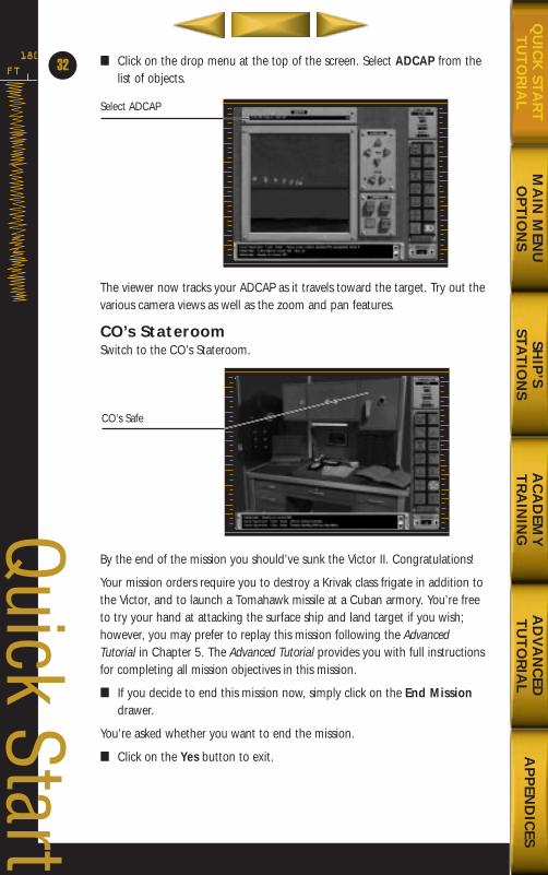
3-D ViewerSwitch to the 3-D Viewer station.
Notice as the torpedo is launched from your submarine.
31
MA
IN M
ENU
OP
TIO
NS
SHIP
’S STA
TIO
NS
AC
AD
EMY
TR
AIN
ING
AD
VA
NC
EDT
UT
OR
IAL
AP
PEN
DIC
ESQ
UIC
K STA
RT
TU
TO
RIA
L
688(i)/AttackSubChptr1 5/6/98 10:11 AM Page 33
FT
180 ■ Click on the drop menu at the top of the screen. Select ADCAP from thelist of objects.
The viewer now tracks your ADCAP as it travels toward the target. Try out thevarious camera views as well as the zoom and pan features.
CO’s StateroomSwitch to the CO’s Stateroom.
By the end of the mission you should’ve sunk the Victor II. Congratulations!
Your mission orders require you to destroy a Krivak class frigate in addition tothe Victor, and to launch a Tomahawk missile at a Cuban armory. You’re freeto try your hand at attacking the surface ship and land target if you wish;however, you may prefer to replay this mission following the AdvancedTutorial in Chapter 5. The Advanced Tutorial provides you with full instructionsfor completing all mission objectives in this mission.
■ If you decide to end this mission now, simply click on the End Missiondrawer.
You’re asked whether you want to end the mission.
■ Click on the Yes button to exit.
32
Quick Start
Select ADCAP
CO’s Safe
MA
IN M
ENU
OP
TIO
NS
SHIP
’S STA
TIO
NS
AC
AD
EMY
TR
AIN
ING
AD
VA
NC
EDT
UT
OR
IAL
AP
PEN
DIC
ESQ
UIC
K STA
RT
TU
TO
RIA
L
688(i)/AttackSubChptr1 5/6/98 10:12 AM Page 34
SHIP
’S STA
TIO
NS
AC
AD
EMY
TR
AIN
ING
AD
VA
NC
EDT
UT
OR
IAL
AP
PEN
DIC
ESQ
UIC
K STA
RT
TU
TO
RIA
LM
AIN
MEN
UO
PT
ION
S
688(i)/AttackSubChptr1 5/6/98 10:55 AM Page 35
Chapter 2: Main Menu/OptionsCHANGE OF COMMAND SCREEN ................................35
MAIN MENU ................................................................36Training Mission ...........................................................................36Training Missions .........................................................................37Single Mission ...............................................................................37Campaign ......................................................................................39Mission Editor ...............................................................................39Mission Editor Hot Keys .............................................................44Multiplayer .....................................................................................45Captain’s Log.................................................................................50Ship’s Information Books .............................................................51Info On-Line ..................................................................................51Options ..........................................................................................52Exit to Windows ..........................................................................54
IN PORT ......................................................................54Weapons Depot .............................................................................55Repair Yard......................................................................................56
GENERAL INFORMATION (GEN INFO) AREA ................56Control Panel.................................................................................58
SAVING A MISSION OR CAMPAIGN ............................60
34FT
180
Main M
enu/Options
SHIP
’SSTA
TIO
NS
AC
AD
EMY
TR
AIN
ING
AD
VA
NC
EDT
UT
OR
IAL
AP
PEN
DIC
ESQ
UIC
K STA
RT
TU
TO
RIA
LM
AIN
MEN
UO
PT
ION
S
SHIP
’S STA
TIO
NS
AC
AD
EMY
TR
AIN
ING
AD
VA
NC
EDT
UT
OR
IAL
AP
PEN
DIC
ESQ
UIC
K STA
RT
TU
TO
RIA
LM
AIN
MEN
UO
PT
ION
S
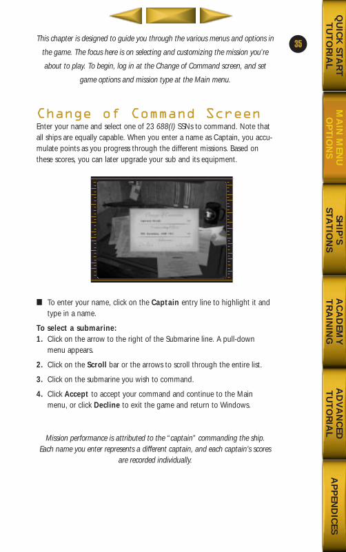
This chapter is designed to guide you through the various menus and options in
the game. The focus here is on selecting and customizing the mission you’re
about to play. To begin, log in at the Change of Command screen, and set
game options and mission type at the Main menu.
Change of Command ScreenEnter your name and select one of 23 688(I) SSNs to command. Note thatall ships are equally capable. When you enter a name as Captain, you accu-mulate points as you progress through the different missions. Based onthese scores, you can later upgrade your sub and its equipment.
■ To enter your name, click on the Captain entry line to highlight it andtype in a name.
To select a submarine:1. Click on the arrow to the right of the Submarine line. A pull-down
menu appears.
2. Click on the Scroll bar or the arrows to scroll through the entire list.
3. Click on the submarine you wish to command.
4. Click Accept to accept your command and continue to the Mainmenu, or click Decline to exit the game and return to Windows.
Mission performance is attributed to the “captain” commanding the ship. Each name you enter represents a different captain, and each captain’s scores
are recorded individually.
35
688(i)/AttackSubChptr2 5/6/98 10:28 AM Page 1
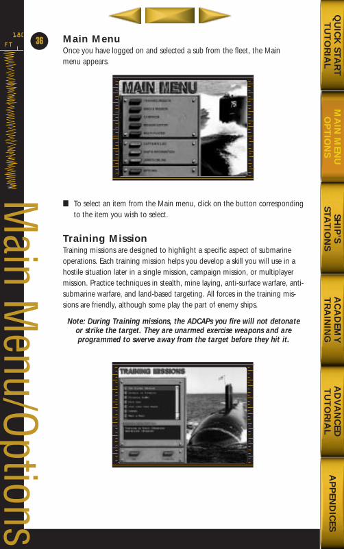
Main MenuOnce you have logged on and selected a sub from the fleet, the Main menu appears.
■ To select an item from the Main menu, click on the button correspondingto the item you wish to select.
Training MissionTraining missions are designed to highlight a specific aspect of submarineoperations. Each training mission helps you develop a skill you will use in ahostile situation later in a single mission, campaign mission, or multiplayermission. Practice techniques in stealth, mine laying, anti-surface warfare, anti-submarine warfare, and land-based targeting. All forces in the training mis-sions are friendly, although some play the part of enemy ships.
Note: During Training missions, the ADCAPs you fire will not detonateor strike the target. They are unarmed exercise weapons and are programmed to swerve away from the target before they hit it.
FT
180
36
Main M
enu/Options
SHIP
’S STA
TIO
NS
AC
AD
EMY
TR
AIN
ING
AD
VA
NC
EDT
UT
OR
IAL
AP
PEN
DIC
ESQ
UIC
K STA
RT
TU
TO
RIA
LM
AIN
MEN
UO
PT
ION
S
688(i)/AttackSubChptr2 5/6/98 10:28 AM Page 2
SHIP
’S STA
TIO
NS
AC
AD
EMY
TR
AIN
ING
AD
VA
NC
EDT
UT
OR
IAL
AP
PEN
DIC
ESQ
UIC
K STA
RT
TU
TO
RIA
LM
AIN
MEN
UO
PT
ION
S
To play a Training Mission:1. Click the button next to TRAINING MISSION. The Training Mission Select
screen appears.
2. Click on the mission of your choice. A mission summary appears in theMission Description box.
3. When you have selected the mission you wish to play, click the OKbutton. You are taken to the Port of Call. For more information, see Port of Call on p. 54.
Training MissionsThe Silent Service Training in basic submarine operations,
focusing on stealth.
Assault On Freeport Training in strike warfare and targeting the Tomahawk missile.
Virginia SLMMs Training in offensive mine warfare.
Fire One! Training in basic anti-submarine warfare (ASW).
Just Like John Wayne Training in basic anti-surface unit warfare (ASUW) employing ADCAP torpedoes.
SINKEX Training in basic anti-surface unit warfare(ASUW) employing Harpoon anti-ship
missiles.
Mano a Mano Training in advanced anti-submarine warfare.
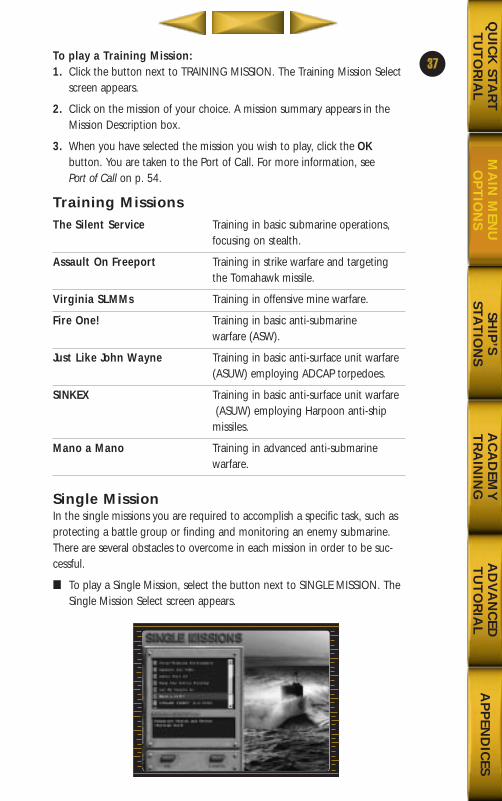
Single MissionIn the single missions you are required to accomplish a specific task, such asprotecting a battle group or finding and monitoring an enemy submarine.There are several obstacles to overcome in each mission in order to be suc-cessful.
■ To play a Single Mission, select the button next to SINGLE MISSION. TheSingle Mission Select screen appears.
37
688(i)/AttackSubChptr2 5/6/98 10:28 AM Page 3
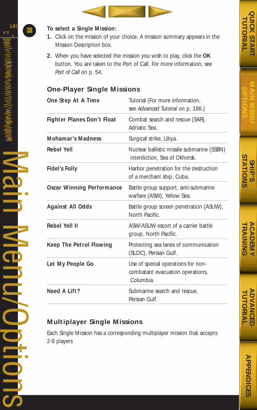
To select a Single Mission:1. Click on the mission of your choice. A mission summary appears in the
Mission Description box.
2. When you have selected the mission you wish to play, click the OKbutton. You are taken to the Port of Call. For more information, see Port of Call on p. 54.
One-Player Single Missions
One Step At A Time Tutorial (For more information, see Advanced Tutorial on p. 186.)
Fighter Planes Don’t Float Combat search and rescue (SAR), Adriatic Sea.
Mohamar’s Madness Surgical strike, Libya.
Rebel Yell Nuclear ballistic missile submarine (SSBN)interdiction, Sea of Okhotsk.
Fidel’s Folly Harbor penetration for the destruction of a merchant ship, Cuba.
Oscar Winning Performance Battle group support, anti-submarine warfare (ASW), Yellow Sea.
Against All Odds Battle group screen penetration (ASUW), North Pacific.
Rebel Yell II ASW/ASUW escort of a carrier battle group, North Pacific.
Keep The Petrol Flowing Protecting sea lanes of communication (SLOC), Persian Gulf.
Let My People Go Use of special operations for non-combatant evacuation operations,Columbia.
Need A Lift? Submarine search and rescue, Persian Gulf.
Multiplayer Single Missions
Each Single Mission has a corresponding multiplayer mission that accepts 2-8 players
FT
180
38
Main M
enu/Options
SHIP
’S STA
TIO
NS
AC
AD
EMY
TR
AIN
ING
AD
VA
NC
EDT
UT
OR
IAL
AP
PEN
DIC
ESQ
UIC
K STA
RT
TU
TO
RIA
LM
AIN
MEN
UO
PT
ION
S
688(i)/AttackSubChptr2 5/6/98 10:28 AM Page 4
SHIP
’S STA
TIO
NS
AC
AD
EMY
TR
AIN
ING
AD
VA
NC
EDT
UT
OR
IAL
AP
PEN
DIC
ESQ
UIC
K STA
RT
TU
TO
RIA
LM
AIN
MEN
UO
PT
ION
S
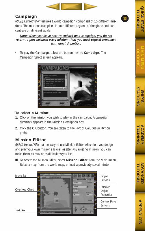
Campaign688(I) Hunter/Killer features a world campaign comprised of 15 different mis-sions. The missions take place in four different regions of the globe and con-centrate on different goals.
Note: When you leave port to embark on a campaign, you do notreturn to port between every mission; thus, you must expend armament
with great discretion.
• To play the Campaign, select the button next to Campaign. TheCampaign Select screen appears.
To select a Mission:1. Click on the mission you wish to play in the campaign. A campaign
summary appears in the Mission Description box.
2. Click the OK button. You are taken to the Port of Call. See In Port on p. 54.
Mission Editor688(I) Hunter/Killer has an easy-to-use Mission Editor which lets you designand play your own missions as well as alter any existing mission. You canmake them as easy or as difficult as you like.
■ To access the Mission Editor, select Mission Editor from the Main menu.Select a map from the world map, or load a previously saved mission.
39
Menu Bar
Overhead Chart
Text Box
ObjectButtons
SelectedObjectProperties
Control PanelButtons
688(i)/AttackSubChptr2 5/6/98 10:28 AM Page 5
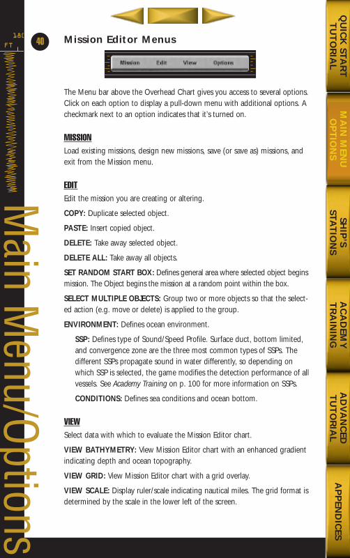
Mission Editor Menus
The Menu bar above the Overhead Chart gives you access to several options.Click on each option to display a pull-down menu with additional options. Acheckmark next to an option indicates that it’s turned on.
MISSIONLoad existing missions, design new missions, save (or save as) missions, andexit from the Mission menu.
EDITEdit the mission you are creating or altering.
COPY: Duplicate selected object.
PASTE: Insert copied object.
DELETE: Take away selected object.
DELETE ALL: Take away all objects.
SET RANDOM START BOX: Defines general area where selected object beginsmission. The Object begins the mission at a random point within the box.
SELECT MULTIPLE OBJECTS: Group two or more objects so that the select-ed action (e.g. move or delete) is applied to the group.
ENVIRONMENT: Defines ocean environment.
SSP: Defines type of Sound/Speed Profile. Surface duct, bottom limited,and convergence zone are the three most common types of SSPs. Thedifferent SSPs propagate sound in water differently, so depending onwhich SSP is selected, the game modifies the detection performance of allvessels. See Academy Training on p. 100 for more information on SSPs.
CONDITIONS: Defines sea conditions and ocean bottom.
VIEWSelect data with which to evaluate the Mission Editor chart.
VIEW BATHYMETRY: View Mission Editor chart with an enhanced gradientindicating depth and ocean topography.
VIEW GRID: View Mission Editor chart with a grid overlay.
VIEW SCALE: Display ruler/scale indicating nautical miles. The grid format isdetermined by the scale in the lower left of the screen.
FT
180
40
Main M
enu/Options
SHIP
’S STA
TIO
NS
AC
AD
EMY
TR
AIN
ING
AD
VA
NC
EDT
UT
OR
IAL
AP
PEN
DIC
ESQ
UIC
K STA
RT
TU
TO
RIA
LM
AIN
MEN
UO
PT
ION
S
688(i)/AttackSubChptr2 5/6/98 10:28 AM Page 6
SHIP
’S STA
TIO
NS
AC
AD
EMY
TR
AIN
ING
AD
VA
NC
EDT
UT
OR
IAL
AP
PEN
DIC
ESQ
UIC
K STA
RT
TU
TO
RIA
LM
AIN
MEN
UO
PT
ION
S
OPTIONSManipulate objects and messages.
ADD MULTIPLAYER SUB: Place a 688(I) for a multiplayer mission.
ADD WAYPOINT: Place an additional waypoint for selected object. (Exceptfor OwnShip and Multiplayer Sub.)
ADD MINEFIELD: Place a minefield.
DEFINE BRIEF: Create or alter the commanding officer’s mission brief whichappears at the Port Of Call Command Center and on the laptop in the CO’sstateroom. If this is an existing mission, you can alter this to fit the changesyou make to the mission. If this is a new mission, define the objectives andgoals of your created mission.
DEFINE SCENARIO NAME: Create or alter the scenario name which appearsat the Mission Menu.
DEFINE INTELLIGENCE MESSAGE: Create or alter the intelligence messagewhich is broadcast during the mission.
DEFINE TASKING MESSAGE: The tasking message is the first message youreceive when you begin your mission and it appears on the message screenin the Radio room. It will often give more precise information than the brief,especially as to latitude and longitude. If this is an existing mission, you canalter the message to fit the changes you’ve made to the mission.
Using the Mission EditorThis section briefly describes how to create new missions, alter existing mis-sions, save edited missions, and load edited missions.
To create a new Mission: When the Mission Editor first appears, it is readyfor your input. If you are building or editing a mission and you want to beginanother, select New Mission from the Mission pull-down.
To load an existing Mission for editing:1. Select Load Mission from the Mission pull-down. The Mission menu
appears.
2. Select the mission you wish to load, then click OK.
To save a Mission:1. Select Save Mission from the Mission pull-down. The Save or Save As
screen appears.
2. Type a name to label the mission you wish to save, then click OK. Themission is saved as a Single Mission.
41
688(i)/AttackSubChptr2 5/6/98 10:28 AM Page 7
Creating MissionsThis section demonstrates the steps necessary to create a new mission. Thesame principles apply to editing existing missions.
To create a mission, you must first specify a geographical area in which youwant the mission to take place and you must select and place friendly andenemy vessels, mines, and land-based targets on the chart.■ To scroll the chart, place the cursor anywhere on the chart.■ To select an object, click on the object.■ To move an object, click on the object and drag it.■ To view the latitude/longitude and depth of a given locus, move the cur-
sor to the locus on the map and hold iq , or press X to toggle thisoption on/off.
To specify a locus:1. Select Mission Editor from the Main menu. The Mission Editor appears.
2. Move the cursor over the Chart and over the area in which you want themission to take place, then right-click. A confirmation text box appears
3. Click Yes to load the selected geographic area. The area loads. (Click Noto cancel and select another area from the chart.
4. Your submarine (own ship) will automatically be placed on the chart.
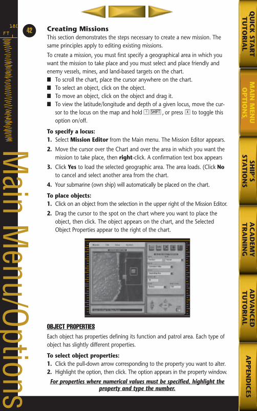
To place objects:1. Click on an object from the selection in the upper right of the Mission Editor.
2. Drag the cursor to the spot on the chart where you want to place theobject, then click. The object appears on the chart, and the SelectedObject Properties appear to the right of the chart.
OBJECT PROPERTIESEach object has properties defining its function and patrol area. Each type ofobject has slightly different properties.
To select object properties:1. Click the pull-down arrow corresponding to the property you want to alter.2. Highlight the option, then click. The option appears in the property window.
For properties where numerical values must be specified, highlight theproperty and type the number.
FT
18042
Main M
enu/Options
SHIP
’SSTA
TIO
NS
AC
AD
EMY
TR
AIN
ING
AD
VA
NC
EDT
UT
OR
IAL
AP
PEN
DIC
ESQ
UIC
K STA
RT
TU
TO
RIA
LM
AIN
MEN
UO
PT
ION
S
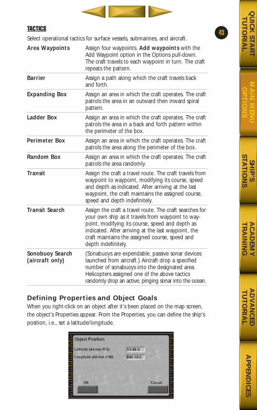
SHIP
’S STA
TIO
NS
AC
AD
EMY
TR
AIN
ING
AD
VA
NC
EDT
UT
OR
IAL
AP
PEN
DIC
ESQ
UIC
K STA
RT
TU
TO
RIA
LM
AIN
MEN
UO
PT
ION
S
TACTICSSelect operational tactics for surface vessels, submarines, and aircraft.
Area Waypoints Assign four waypoints. Add waypoints with the Add Waypoint option in the Options pull-down. The craft travels to each waypoint in turn. The craft repeats the pattern.
Barrier Assign a path along which the craft travels back and forth.
Expanding Box Assign an area in which the craft operates. The craftpatrols the area in an outward then inward spiral pattern.
Ladder Box Assign an area in which the craft operates. The craftpatrols the area in a back and forth pattern within the perimeter of the box.
Perimeter Box Assign an area in which the craft operates. The craft patrols the area along the perimeter of the box.
Random Box Assign an area in which the craft operates. The craftpatrols the area randomly.
Transit Assign the craft a travel route. The craft travels fromwaypoint to waypoint, modifying its course, speed and depth as indicated. After arriving at the last waypoint, the craft maintains the assigned course, speed and depth indefinitely.
Transit Search Assign the craft a travel route. The craft searches foryour own ship as it travels from waypoint to way-point, modifying its course, speed and depth as indicated. After arriving at the last waypoint, the craft maintains the assigned course, speed and depth indefinitely.
Sonobuoy Search (Sonabuoys are expendable, passive sonar devices(aircraft only) launched from aircraft.) Aircraft drop a specified
number of sonabuoys into the designated area.Helicopters assigned one of the above tactics randomly drop an active, pinging sonar into the ocean.
Defining Properties and Object GoalsWhen you right-click on an object after it’s been placed on the map screen,the object’s Properties appear. From the Properties, you can define the ship’sposition, i.e., set a latitude/longitude.
43
688(i)/AttackSubChptr2 5/6/98 10:28 AM Page 9
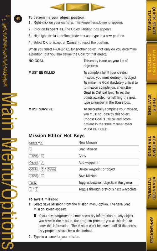
To determine your object position:1. Right-click on your ownship. The Properties sub-menu appears.
2. Click on Properties. The Object Position box appears.
3. Highlight the latitude/longitude box and type in a new position.
4. Select OK to accept or Cancel to reject the position.
When you select PROPERTIES for another object, not only do you determinea position, but you also define the Goal for that object.
NO GOAL This entity is not on your list of objectives.
MUST BE KILLED To complete fulfill your created mission, you must destroy this object.To make the Goal absolutely critical toto mission completion, check the Goal is Critical box. To set the points awarded for fulfilling the goal, type a number in the Score box.
MUST SURVIVE To successfully complete your mission,you must not destroy this object. Choose Goal is Critical and Score options in the same manner as for MUST BE KILLED.
Mission Editor Hot KeysC+N New Mission
L Load Mission
S / U Copy
S / A Add waypoint
S / D / D Delete waypoint or object
S / S Save Mission
T Toggles between objects in the game
[ / ] Toggle through previous/next waypoints
To save a mission:1. Select Save Mission from the Mission menu option. The Save/Load
Mission screen appears.
■ If you have forgotten to enter necessary information on any objectyou have in the mission, the program prompts you at this time toenter this information. The Mission can’t be saved until all the neces-sary properties have been determined.
2. Type in a name for your mission.
FT
180
44
Main M
enu/Options
SHIP
’S STA
TIO
NS
AC
AD
EMY
TR
AIN
ING
AD
VA
NC
EDT
UT
OR
IAL
AP
PEN
DIC
ESQ
UIC
K STA
RT
TU
TO
RIA
LM
AIN
MEN
UO
PT
ION
S
688(i)/AttackSubChptr2 5/6/98 10:28 AM Page 10
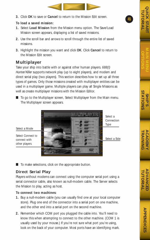
SHIP
’S STA
TIO
NS
AC
AD
EMY
TR
AIN
ING
AD
VA
NC
EDT
UT
OR
IAL
AP
PEN
DIC
ESQ
UIC
K STA
RT
TU
TO
RIA
LM
AIN
MEN
UO
PT
ION
S
3. Click OK to save or Cancel to return to the Mission Edit screen.
To load a saved mission: 1. Select Load Mission from the Mission menu option. The Save/Load
Mission screen appears, displaying a list of saved missions.
2. Use the scroll bar and arrows to scroll through the entire list of saved missions.
3. Highlight the mission you want and click OK. Click Cancel to return tothe Mission Edit screen.
MultiplayerTake your ship into battle with or against other human players. 688(I)Hunter/Killer supports network play (up to eight players), and modem anddirect serial play (two players). This section describes how to set up all threetypes of games. Only those missions created with multiplayer entities can beused in a multiplayer game. Multiple players can play all Single Missions aswell as create multiplayer missions with the Mission Editor.
■ To go to the Multiplayer screen, Select Multiplayer from the Main menu.The Multiplayer screen appears.
■ To make selections, click on the appropriate button.
Direct Serial PlayPlayers without modems can connect using the computer serial port using aserial connector cable, also known as null-modem cable. The Server selectsthe Mission to play, acting as host.
To connect two machines: 1. Buy a null-modem cable (you can usually find one at your local computer
store). Plug one end of the connector into a serial port on one machine,and the other end into a serial port on the second machine.
2. Remember which COM port you plugged the cable into. You’ll need toknow this when attempting to connect to the other machine. (COM 1 isusually used by your mouse.) If you’re not sure what port you’re using,look on the back of your computer. Most ports have an identifying mark.
45
Select a Mode
Select Connect toconnect withother players
Select aConnectionType
Select a Side
688(i)/AttackSubChptr2 5/6/98 10:28 AM Page 11
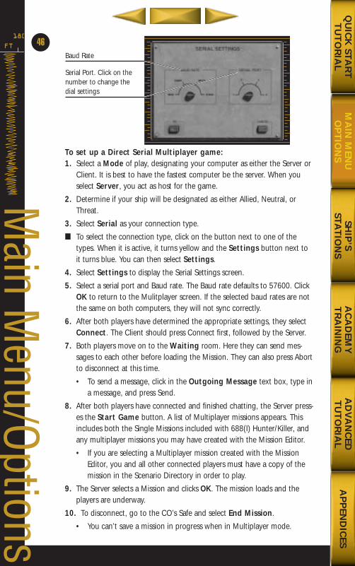
To set up a Direct Serial Multiplayer game:1. Select a Mode of play, designating your computer as either the Server or
Client. It is best to have the fastest computer be the server. When youselect Server, you act as host for the game.
2. Determine if your ship will be designated as either Allied, Neutral, orThreat.
3. Select Serial as your connection type.
■ To select the connection type, click on the button next to one of thetypes. When it is active, it turns yellow and the Settings button next toit turns blue. You can then select Settings.
4. Select Settings to display the Serial Settings screen.
5. Select a serial port and Baud rate. The Baud rate defaults to 57600. ClickOK to return to the Mulitplayer screen. If the selected baud rates are notthe same on both computers, they will not sync correctly.
6. After both players have determined the appropriate settings, they selectConnect. The Client should press Connect first, followed by the Server.
7. Both players move on to the Waiting room. Here they can send mes-sages to each other before loading the Mission. They can also press Abortto disconnect at this time.
• To send a message, click in the Outgoing Message text box, type ina message, and press Send.
8. After both players have connected and finished chatting, the Server press-es the Start Game button. A list of Multiplayer missions appears. Thisincludes both the Single Missions included with 688(I) Hunter/Killer, andany multiplayer missions you may have created with the Mission Editor.
• If you are selecting a Multiplayer mission created with the MissionEditor, you and all other connected players must have a copy of themission in the Scenario Directory in order to play.
9. The Server selects a Mission and clicks OK. The mission loads and theplayers are underway.
10. To disconnect, go to the CO’s Safe and select End Mission.
• You can’t save a mission in progress when in Multiplayer mode.
FT
180
46
Main M
enu/Options
Baud Rate
Serial Port. Click on thenumber to change thedial settings
SHIP
’S STA
TIO
NS
AC
AD
EMY
TR
AIN
ING
AD
VA
NC
EDT
UT
OR
IAL
AP
PEN
DIC
ESQ
UIC
K STA
RT
TU
TO
RIA
LM
AIN
MEN
UO
PT
ION
S
688(i)/AttackSubChptr2 5/6/98 10:28 AM Page 12
SHIP
’S STA
TIO
NS
AC
AD
EMY
TR
AIN
ING
AD
VA
NC
EDT
UT
OR
IAL
AP
PEN
DIC
ESQ
UIC
K STA
RT
TU
TO
RIA
LM
AIN
MEN
UO
PT
ION
S
To communicate with other players during a mission: 1. Go to the Radio Room. A text box appears above the Radio message
screen, and a Send Message button appears next to the box.
2. Highlight the box and type in a message. Press Send Message to sendthe message.
The message appears in the general information text box along the bottomof the game screen and in the Radio Room Message screen. Look for mes-sages from other players in these areas as well.
Modem PlayTwo players can connect directly by a 28,800 baud or faster modem. TheServer selects the mission to be played, and acts as the caller.
Note: Your modem must be installed through the Windows 95Operating System before you begin the game. If you haven’t installed
your modem through Windows 95, consult your Windows 95 andmodem documentation to learn how.
To setup a Modem Multiplayer game:1. Select a Mode of play, designating your computer as either the Server
or Client. It is best to have the fastest computer be the server. When youselect Server, you act as host for the game. The Server is in “Call Mode”,while the Client receives, or acts in the “Answer Mode”.
2. Determine if your ship will be designated as either Allied, Neutral,or Threat.
3. Select Modem as your connection type.
■ To select the connection type, click on the button next to one of thetypes. When it is active, it turns yellow and the Settings button next toit turns blue. You can then select Settings.
4. Select Settings to display the Modem Settings screen. The server mustselect a telephone number from the list, or type in the appropriate number.
5. Both players must select a Modem port. Select Auto to have your systemautomatically detect the modem port. Press OK to return to theMultiplayer screen.
6. Both players press Connect and move on to the Waiting room. They waitwhile the server’s machine dials and connects with the client.
7. The Start Game button is automatically activated in two-player games(Serial Modem). After both players have connected a list of Multiplayermissions appears. This includes both the Single Missions included with688(I) Hunter/Killer and any multiplayer missions you may have createdwith the Mission Editor.
• If you are selecting a Multiplayer mission created with the MissionEditor, you and all other connected players must have a copy of themission in order to play.
47
688(i)/AttackSubChptr2 5/6/98 10:28 AM Page 13
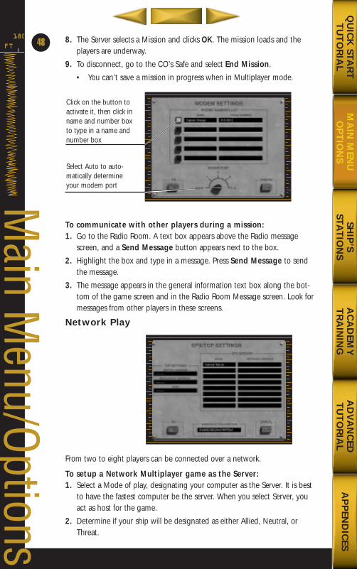
8. The Server selects a Mission and clicks OK. The mission loads and theplayers are underway.
9. To disconnect, go to the CO’s Safe and select End Mission.
• You can’t save a mission in progress when in Multiplayer mode.
To communicate with other players during a mission: 1. Go to the Radio Room. A text box appears above the Radio message
screen, and a Send Message button appears next to the box.
2. Highlight the box and type in a message. Press Send Message to sendthe message.
3. The message appears in the general information text box along the bot-tom of the game screen and in the Radio Room Message screen. Look formessages from other players in these screens.
Network Play
From two to eight players can be connected over a network.
To setup a Network Multiplayer game as the Server:1. Select a Mode of play, designating your computer as the Server. It is best
to have the fastest computer be the server. When you select Server, youact as host for the game.
2. Determine if your ship will be designated as either Allied, Neutral, orThreat.
FT
180
48
Main M
enu/Options
Click on the button toactivate it, then click inname and number boxto type in a name andnumber box
Select Auto to auto-matically determineyour modem port
SHIP
’S STA
TIO
NS
AC
AD
EMY
TR
AIN
ING
AD
VA
NC
EDT
UT
OR
IAL
AP
PEN
DIC
ESQ
UIC
K STA
RT
TU
TO
RIA
LM
AIN
MEN
UO
PT
ION
S
688(i)/AttackSubChptr2 5/6/98 10:28 AM Page 14
SHIP
’S STA
TIO
NS
AC
AD
EMY
TR
AIN
ING
AD
VA
NC
EDT
UT
OR
IAL
AP
PEN
DIC
ESQ
UIC
K STA
RT
TU
TO
RIA
LM
AIN
MEN
UO
PT
ION
S
3. Select the Network connection type.
■ To select the connection type, click on the button next to one of thetypes. When it is active, it turns yellow and the Settings button next toturns blue. You can then select Settings.
4. Select Connect. You go to the Waiting room, where you wait for theother players, or clients, to join you.
5. After everyone has connected and finished chatting, you press the Start Game button. A list of Multiplayer missions appears. This includesboth the Single Missions included with 688(I) Hunter/Killer, and any mul-tiplayer missions you may have created with the Mission Editor.
• If you are selecting a Multiplayer mission created with the MissionEditor, you and all other connected players must have a copy of themission in order to play.
6. The Server selects a Mission and clicks OK. The mission loads and theplayers are underway.
7. To disconnect, go to the CO’s Safe and select End Mission.
• You can’t save a mission in progress when in Multiplayer mode.
To setup a Network Multiplayer game as a client: 1. Select a Mode of play, designating your computer as the Client.
2. Determine if your ship will be designated as either Allied, Neutral, orThreat.
3. Select the Network connection type.
• To select the connection type, click on the button next to one of thetypes. When it is active, it turns yellow and the Settings button nextto turns blue. You can then select Settings.
4. Select Connect. You go to the Connection room, where you can select aServer from a list of available servers by double-clicking on the Servername. You then go to the Waiting room where you can wait for the otherplayers, or clients, to join the game
5. After everyone has connected and finished chatting, the Server pressesthe Start Game button to to load a scenario.
• All connected players must have a copy of the mission in order to play.
6. The Server selects a Mission and clicks OK. The mission loads and theplayers are underway.
7. Clients can disconnect at any time. To disconnect, go to the CO’s Safeand select End Mission. If the server player disconnects, the game willcontinue, although the players’ positions will not be as accurate and mayappear jumpy.
• You can’t save a mission in progress when in Multiplayer mode.
49
688(i)/AttackSubChptr2 5/6/98 10:28 AM Page 15
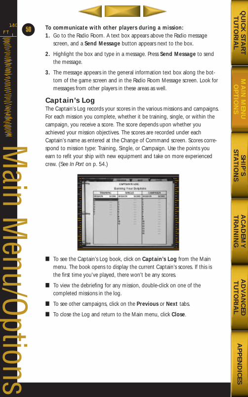
To communicate with other players during a mission: 1. Go to the Radio Room. A text box appears above the Radio message
screen, and a Send Message button appears next to the box.
2. Highlight the box and type in a message. Press Send Message to sendthe message.
3. The message appears in the general information text box along the bot-tom of the game screen and in the Radio Room Message screen. Look formessages from other players in these areas as well.
Captain’s LogThe Captain’s Log records your scores in the various missions and campaigns.For each mission you complete, whether it be training, single, or within thecampaign, you receive a score. The score depends upon whether youachieved your mission objectives. The scores are recorded under eachCaptain’s name as entered at the Change of Command screen. Scores corre-spond to mission type: Training, Single, or Campaign. Use the points youearn to refit your ship with new equipment and take on more experiencedcrew. (See In Port on p. 54.)
■ To see the Captain’s Log book, click on Captain’s Log from the Mainmenu. The book opens to display the current Captain’s scores. If this isthe first time you’ve played, there won’t be any scores.
■ To view the debriefing for any mission, double-click on one of the completed missions in the log.
■ To see other campaigns, click on the Previous or Next tabs.
■ To close the Log and return to the Main menu, click Close.
FT
180
50
Main M
enu/Options
SHIP
’S STA
TIO
NS
AC
AD
EMY
TR
AIN
ING
AD
VA
NC
EDT
UT
OR
IAL
AP
PEN
DIC
ESQ
UIC
K STA
RT
TU
TO
RIA
LM
AIN
MEN
UO
PT
ION
S
688(i)/AttackSubChptr2 5/6/98 10:28 AM Page 16
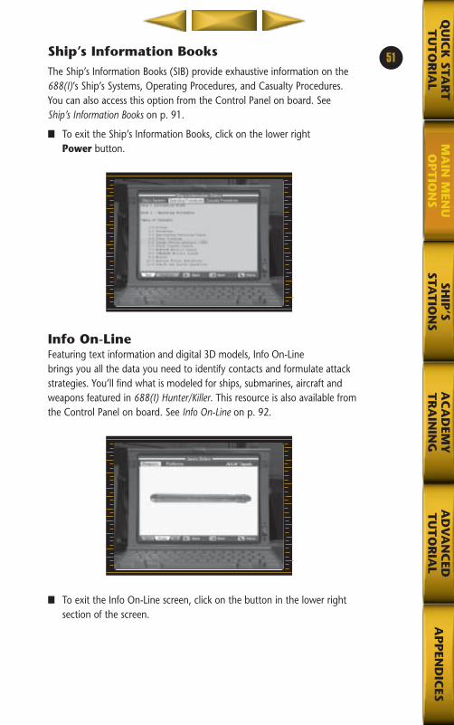
SHIP
’SSTA
TIO
NS
AC
AD
EMY
TR
AIN
ING
AD
VA
NC
EDT
UT
OR
IAL
AP
PEN
DIC
ESQ
UIC
K STA
RT
TU
TO
RIA
LM
AIN
MEN
UO
PT
ION
S
Ship’s Information BooksThe Ship’s Information Books (SIB) provide exhaustive information on the688(I)’s Ship’s Systems, Operating Procedures, and Casualty Procedures. You can also access this option from the Control Panel on board. See Ship’s Information Books on p. 91.
■ To exit the Ship’s Information Books, click on the lower right Power button.
Info On-LineFeaturing text information and digital 3D models, Info On-Linebrings you all the data you need to identify contacts and formulate attackstrategies. You’ll find what is modeled for ships, submarines, aircraft andweapons featured in 688(I) Hunter/Killer. This resource is also available fromthe Control Panel on board. See Info On-Line on p. 92.
■ To exit the Info On-Line screen, click on the button in the lower rightsection of the screen.
51
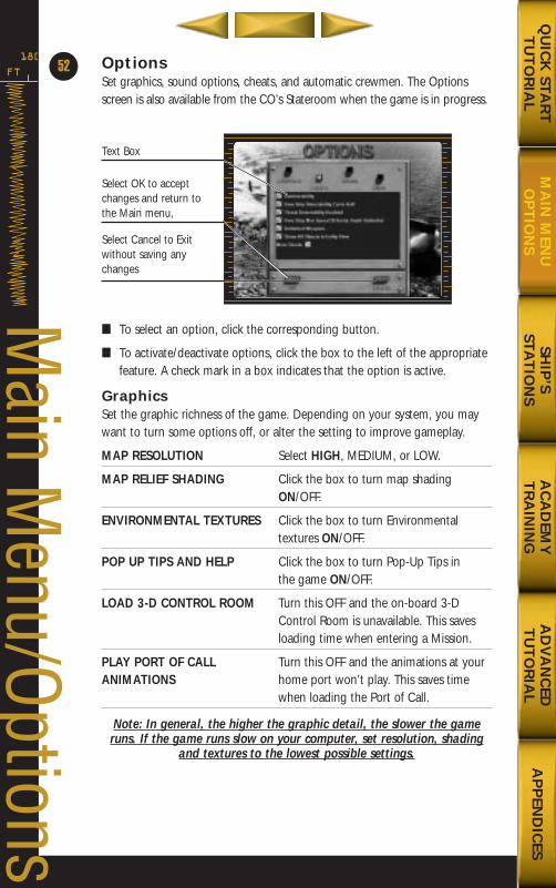
OptionsSet graphics, sound options, cheats, and automatic crewmen. The Optionsscreen is also available from the CO’s Stateroom when the game is in progress.
■ To select an option, click the corresponding button.
■ To activate/deactivate options, click the box to the left of the appropriatefeature. A check mark in a box indicates that the option is active.
GraphicsSet the graphic richness of the game. Depending on your system, you maywant to turn some options off, or alter the setting to improve gameplay.
MAP RESOLUTION Select HIGH, MEDIUM, or LOW.
MAP RELIEF SHADING Click the box to turn map shading ON/OFF.
ENVIRONMENTAL TEXTURES Click the box to turn Environmental textures ON/OFF.
POP UP TIPS AND HELP Click the box to turn Pop-Up Tips in the game ON/OFF.
LOAD 3-D CONTROL ROOM Turn this OFF and the on-board 3-D Control Room is unavailable. This saves loading time when entering a Mission.
PLAY PORT OF CALL Turn this OFF and the animations at yourANIMATIONS home port won’t play. This saves time
when loading the Port of Call.
Note: In general, the higher the graphic detail, the slower the gameruns. If the game runs slow on your computer, set resolution, shading
and textures to the lowest possible settings.
FT
180
52
Main M
enu/Options
Text Box
Select OK to acceptchanges and return tothe Main menu,
Select Cancel to Exitwithout saving anychanges
SHIP
’S STA
TIO
NS
AC
AD
EMY
TR
AIN
ING
AD
VA
NC
EDT
UT
OR
IAL
AP
PEN
DIC
ESQ
UIC
K STA
RT
TU
TO
RIA
LM
AIN
MEN
UO
PT
ION
S
688(i)/AttackSubChptr2 5/6/98 10:29 AM Page 18
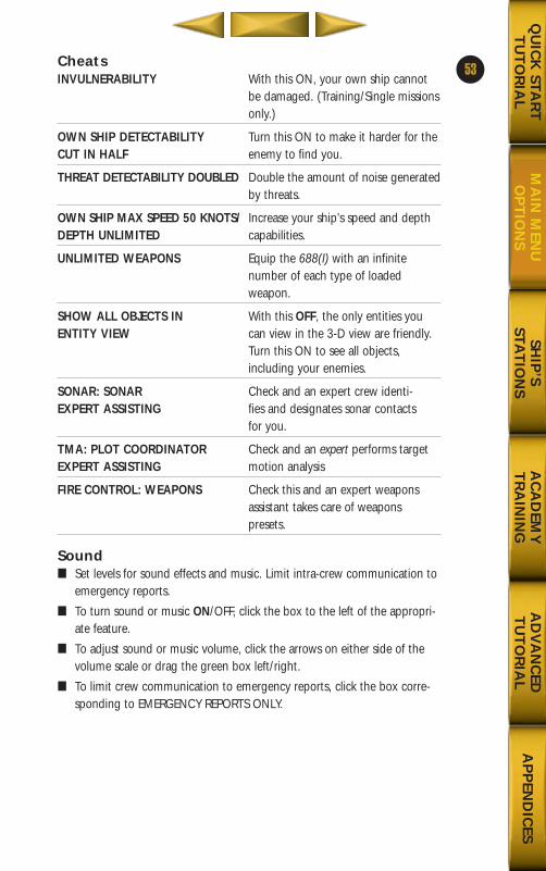
SHIP
’S STA
TIO
NS
AC
AD
EMY
TR
AIN
ING
AD
VA
NC
EDT
UT
OR
IAL
AP
PEN
DIC
ESQ
UIC
K STA
RT
TU
TO
RIA
LM
AIN
MEN
UO
PT
ION
S
CheatsINVULNERABILITY With this ON, your own ship cannot
be damaged. (Training/Single missionsonly.)
OWN SHIP DETECTABILITY Turn this ON to make it harder for theCUT IN HALF enemy to find you.
THREAT DETECTABILITY DOUBLED Double the amount of noise generated by threats.
OWN SHIP MAX SPEED 50 KNOTS/ Increase your ship’s speed and depth DEPTH UNLIMITED capabilities.
UNLIMITED WEAPONS Equip the 688(I) with an infinite number of each type of loaded weapon.
SHOW ALL OBJECTS IN With this OFF, the only entities youENTITY VIEW can view in the 3-D view are friendly.
Turn this ON to see all objects, including your enemies.
SONAR: SONAR Check and an expert crew identi-EXPERT ASSISTING fies and designates sonar contacts
for you.
TMA: PLOT COORDINATOR Check and an expert performs targetEXPERT ASSISTING motion analysis
FIRE CONTROL: WEAPONS Check this and an expert weapons assistant takes care of weapons presets.
Sound■ Set levels for sound effects and music. Limit intra-crew communication to
emergency reports.
■ To turn sound or music ON/OFF, click the box to the left of the appropri-ate feature.
■ To adjust sound or music volume, click the arrows on either side of thevolume scale or drag the green box left/right.
■ To limit crew communication to emergency reports, click the box corre-sponding to EMERGENCY REPORTS ONLY.
53
688(i)/AttackSubChptr2 5/6/98 10:29 AM Page 19
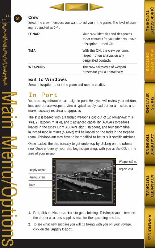
CrewSelect the crew members you want to aid you in the game. The level of train-ing is depicted as 0-4.
SONAR: Your crew identifies and designatessonar contacts for you when you have this option turned ON.
TMA With this ON, the crew performs target motion analysis on any designated contacts.
WEAPONS The crew takes care of weapon presets for you automatically.
Exit to WindowsSelect this option to exit the game and see the credits.
In PortYou start any mission or campaign in port. Here you will review your mission,load appropriate weapons, view a typical supply load out for a mission, andmake necessary repairs and upgrades.
The ship is loaded with a standard weapons load-out of 12 Tomahawk mis-siles, 2 Harpoon missiles, and 2 advanced capability (ADCAP) torpedoesloaded in the tubes. Eight ADCAPs, eight Harpoons, and four submarine-launched mobile mines (SLMMs) will be loaded on the racks in the torpedoroom. This load-out may have to be modified to better suit specific missions.
Once loaded, the ship is ready to get underway by clicking on the subma-rine. Once underway, your ship begins operating, with you as the CO, in thearea of your mission.
1. First, click on Headquarters to get a briefing. This helps you determinethe proper weapons, supplies, etc., for the upcoming mission.
2. To see what new supplies you will be taking with you on your voyage,click on the Supply Depot.
FT
180
54
Main M
enu/OptionsSupply Depot
Headquarters
Buoy
Weapons Shed
Repair Yard
SHIP
’S STA
TIO
NS
AC
AD
EMY
TR
AIN
ING
AD
VA
NC
EDT
UT
OR
IAL
AP
PEN
DIC
ESQ
UIC
K STA
RT
TU
TO
RIA
LM
AIN
MEN
UO
PT
ION
S
688(i)/AttackSubChptr2 5/6/98 10:29 AM Page 20
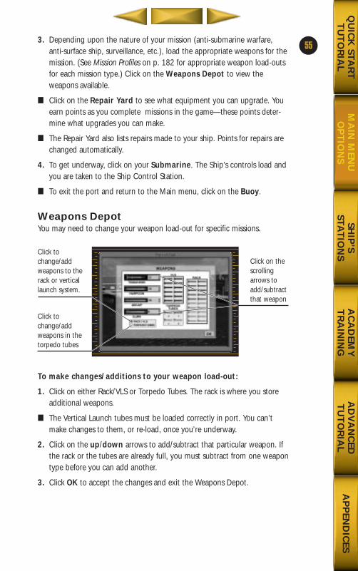
SHIP
’S STA
TIO
NS
AC
AD
EMY
TR
AIN
ING
AD
VA
NC
EDT
UT
OR
IAL
AP
PEN
DIC
ESQ
UIC
K STA
RT
TU
TO
RIA
LM
AIN
MEN
UO
PT
ION
S
3. Depending upon the nature of your mission (anti-submarine warfare,anti-surface ship, surveillance, etc.), load the appropriate weapons for themission. (See Mission Profiles on p. 182 for appropriate weapon load-outsfor each mission type.) Click on the Weapons Depot to view theweapons available.
■ Click on the Repair Yard to see what equipment you can upgrade. Youearn points as you complete missions in the game—these points deter-mine what upgrades you can make.
■ The Repair Yard also lists repairs made to your ship. Points for repairs arechanged automatically.
4. To get underway, click on your Submarine. The Ship’s controls load andyou are taken to the Ship Control Station.
■ To exit the port and return to the Main menu, click on the Buoy.
Weapons DepotYou may need to change your weapon load-out for specific missions.
To make changes/additions to your weapon load-out:
1. Click on either Rack/VLS or Torpedo Tubes. The rack is where you storeadditional weapons.
■ The Vertical Launch tubes must be loaded correctly in port. You can’tmake changes to them, or re-load, once you’re underway.
2. Click on the up/down arrows to add/subtract that particular weapon. Ifthe rack or the tubes are already full, you must subtract from one weapontype before you can add another.
3. Click OK to accept the changes and exit the Weapons Depot.
55
Click tochange/addweapons to therack or verticallaunch system.
Click tochange/addweapons in thetorpedo tubes
Click on thescrollingarrows toadd/subtractthat weapon
688(i)/AttackSubChptr2 5/6/98 10:29 AM Page 21
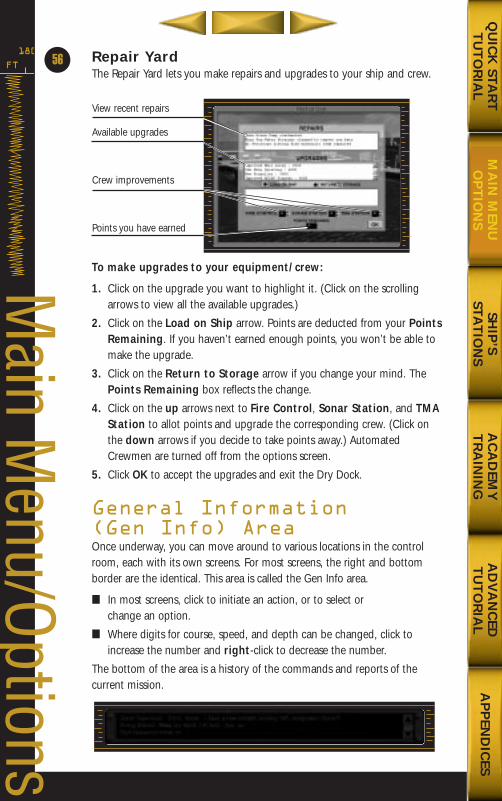
Repair YardThe Repair Yard lets you make repairs and upgrades to your ship and crew.
To make upgrades to your equipment/crew:
1. Click on the upgrade you want to highlight it. (Click on the scrollingarrows to view all the available upgrades.)
2. Click on the Load on Ship arrow. Points are deducted from your PointsRemaining. If you haven’t earned enough points, you won’t be able tomake the upgrade.
3. Click on the Return to Storage arrow if you change your mind. ThePoints Remaining box reflects the change.
4. Click on the up arrows next to Fire Control, Sonar Station, and TMAStation to allot points and upgrade the corresponding crew. (Click onthe down arrows if you decide to take points away.) AutomatedCrewmen are turned off from the options screen.
5. Click OK to accept the upgrades and exit the Dry Dock.
General Information (Gen Info) AreaOnce underway, you can move around to various locations in the controlroom, each with its own screens. For most screens, the right and bottomborder are the identical. This area is called the Gen Info area.
■ In most screens, click to initiate an action, or to select or change an option.
■ Where digits for course, speed, and depth can be changed, click toincrease the number and right-click to decrease the number.
The bottom of the area is a history of the commands and reports of the current mission.
FT
180
56
Main M
enu/Options
View recent repairs
Available upgrades
Crew improvements
Points you have earned
SHIP
’S STA
TIO
NS
AC
AD
EMY
TR
AIN
ING
AD
VA
NC
EDT
UT
OR
IAL
AP
PEN
DIC
ESQ
UIC
K STA
RT
TU
TO
RIA
LM
AIN
MEN
UO
PT
ION
S
688(i)/AttackSubChptr2 5/6/98 10:29 AM Page 22
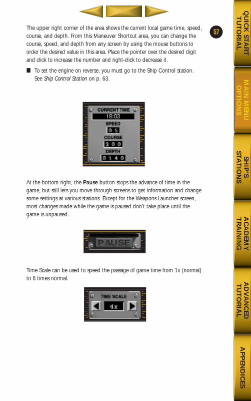
SHIP
’S STA
TIO
NS
AC
AD
EMY
TR
AIN
ING
AD
VA
NC
EDT
UT
OR
IAL
AP
PEN
DIC
ESQ
UIC
K STA
RT
TU
TO
RIA
LM
AIN
MEN
UO
PT
ION
S
The upper right corner of the area shows the current local game time, speed,course, and depth. From this Maneuver Shortcut area, you can change thecourse, speed, and depth from any screen by using the mouse buttons toorder the desired value in this area. Place the pointer over the desired digitand click to increase the number and right-click to decrease it.
■ To set the engine on reverse, you must go to the Ship Control station.See Ship Control Station on p. 63.
At the bottom right, the Pause button stops the advance of time in thegame, but still lets you move through screens to get information and changesome settings at various stations. Except for the Weapons Launcher screen,most changes made while the game is paused don’t take place until thegame is unpaused.
Time Scale can be used to speed the passage of game time from 1x (normal)to 8 times normal.
57
688(i)/AttackSubChptr2 5/6/98 10:29 AM Page 23
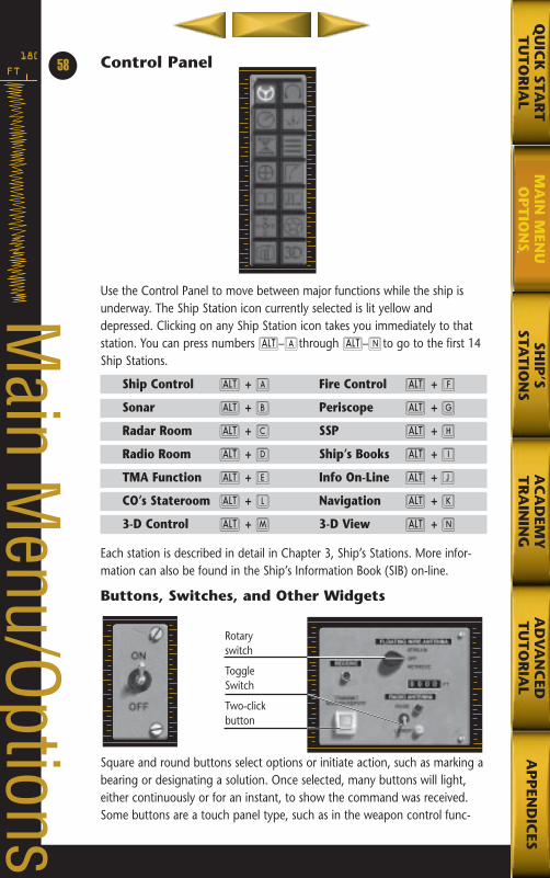
Control Panel
Use the Control Panel to move between major functions while the ship isunderway. The Ship Station icon currently selected is lit yellow anddepressed. Clicking on any Ship Station icon takes you immediately to thatstation. You can press numbers a–Athrough a–Nto go to the first 14Ship Stations.
Ship Control a + A Fire Control a + F
Sonar a + B Periscope a + G
Radar Room a + C SSP a + H
Radio Room a + D Ship’s Books a + I
TMA Function a + E Info On-Line a + J
CO’s Stateroom a + L Navigation a + K
3-D Control a + M 3-D View a + N
Each station is described in detail in Chapter 3, Ship’s Stations. More infor-mation can also be found in the Ship’s Information Book (SIB) on-line.
Buttons, Switches, and Other Widgets
Square and round buttons select options or initiate action, such as marking abearing or designating a solution. Once selected, many buttons will light,either continuously or for an instant, to show the command was received.Some buttons are a touch panel type, such as in the weapon control func-
FT
18058
Main M
enu/OptionsRotaryswitch
ToggleSwitch
Two-clickbutton
SHIP
’SSTA
TIO
NS
AC
AD
EMY
TR
AIN
ING
AD
VA
NC
EDT
UT
OR
IAL
AP
PEN
DIC
ESQ
UIC
K STA
RT
TU
TO
RIA
LM
AIN
MEN
UO
PT
ION
S
SHIP
’S STA
TIO
NS
AC
AD
EMY
TR
AIN
ING
AD
VA
NC
EDT
UT
OR
IAL
AP
PEN
DIC
ESQ
UIC
K STA
RT
TU
TO
RIA
LM
AIN
MEN
UO
PT
ION
S
tion. Also in the weapon control function are oval text windows. These areclicked on to cycle through available options. Triangular buttons are used forincremental movements, such as moving a position on a chart.
Extremely sensitive operations, such as firing a weapon, have buttons thatrequire two clicks—one to raise the cover, and the other to press the button.
Rotary switches are used to allow multiple selections, such as various scales.These are positioned by clicking on the desired position label. Toggle switch-es are used to select one of two options, and are moved by clicking on theswitch. The launch control screen uses a key, which is turned by clicking onthe key. The Emergency Blow Valve is manually positioned by clicking on thehandle.
Some items, such as the entity list in three-dimensions (3-D), have pull-downlists.
■ Click on the down arrow and then click on the desired item in the list.
Objects You Can DragCertain map objects on the Target Display Panel and Mission Editor functioncan be moved from one part of the screen to another. Click-and-hold on thedesired object to select it, and then drag the cursor to a new location.Additionally, the ruler in the target motion analysis (TMA) function can bedragged.
Using the MapsMaps appear in the Navigation screen, the Mission Edit screen, the FireControl screen and during the Replay. The same controls are used in eachmap.
Note: The cursor must be on the map for these controls to work.
59
688(i)/AttackSubChptr2 5/6/98 10:29 AM Page 25
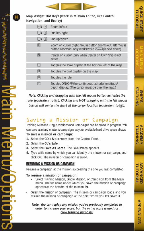
Map Widget Hot Keys (work in Mission Editor, Fire Control,Navigation, and Replay)
+ / - Zoom in/out
j / l Pan left/right
i / k Pan up/down
0 Zoom on cursor (right mouse button zooms out; left mousebutton zooms in; only works while C is held down)
N Center on cursor (only when Center on Own Ship is notactive
T Toggles the scale display at the bottom left of the map
G Toggles the grid display on the map
R Toggles the ruler
X Toggles ON/OFF the continuous latitude/longitude/depth display. (The cursor must be over the map.)
Note: Clicking and dragging with the left mouse button activates theruler (equivalent to R ). Clicking and NOT dragging with the left mouse
button will center the chart at the cursor location (equivalent to N ).
Saving a Mission or CampaignTraining Missions, Single Missions and Campaigns can be saved in progress. Youcan save as many missions/campaigns as your available hard drive space allows.To save a mission or campaign:1. Select the CO’s Stateroom from the Control Panel.2. Select the Co’s Safe.3. Select the Save As Game. The Save screen appears.4. Type a file name by which you can identify the mission or campaign, and
click OK. The mission or campaign is saved.
RESUMING A MISSION OR CAMPAIGNResume a campaign at the mission succeeding the one you last completed.
To resume a mission or campaign:• Select Training Mission, Single Mission, or Campaign from the Main
menu. The file name under which you saved the mission or campaignappears at the bottom of the mission list.
• Select the mission or campaign. The mission or campaign loads, and youresume the mission or campaign at the point where you last saved it.
Note: You can replay any mission you’ve previously completed in order to increase your score, but the initial score is used for
crew training purposes.
FT
180
60
Main M
enu/Options
SHIP
’S STA
TIO
NS
AC
AD
EMY
TR
AIN
ING
AD
VA
NC
EDT
UT
OR
IAL
AP
PEN
DIC
ESQ
UIC
K STA
RT
TU
TO
RIA
LM
AIN
MEN
UO
PT
ION
S
688(i)/AttackSubChptr2 5/6/98 10:29 AM Page 26
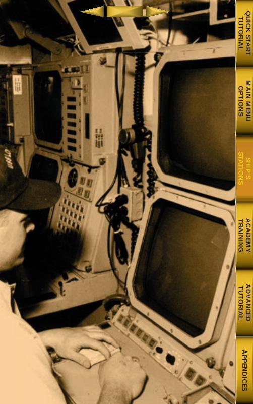
Chapter 1
Qu
ick Start Tu
torial
AC
AD
EMY
TR
AIN
ING
AD
VA
NC
EDT
UT
OR
IAL
AP
PEN
DIC
ESQ
UIC
K STA
RT
TU
TO
RIA
LM
AIN
MEN
UO
PT
ION
SSH
IP’S
STAT
ION
S
688(i)/AttackSubChptr2 5/6/98 10:29 AM Page 27
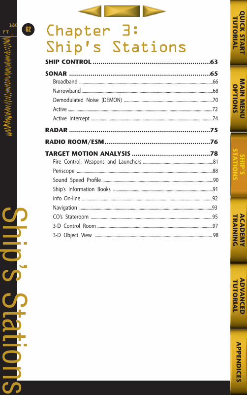
FT
18062
Ship’s Stations
Chapter 3: Ship’s StationsSHIP CONTROL ............................................................63
SONAR ........................................................................65Broadband ..........................................................................................................................66Narrowband ........................................................................................................................68Demodulated Noise (DEMON) .................................................................................70Active ....................................................................................................................................72Active Intercept ...............................................................................................................74
RADAR ........................................................................75
RADIO ROOM/ESM......................................................76
TARGET MOTION ANALYSIS ........................................78Fire Control: Weapons and Launchers ................................................................81Periscope ............................................................................................................................88Sound Speed Pro�le ......................................................................................................90Ship’s Information Books ...........................................................................................91Info On-line .......................................................................................................................92Navigation ..........................................................................................................................93CO’s Stateroom ...............................................................................................................953-D Control Room..........................................................................................................973-D Object View ........................................................................................................... 98
MA
IN M
ENU
OP
TIO
NS
AC
AD
EMY
TR
AIN
ING
AD
VA
NC
EDT
UT
OR
IAL
AP
PEN
DIC
ESQ
UIC
K STA
RT
TU
TO
RIA
LSH
IP’S
STAT
ION
S
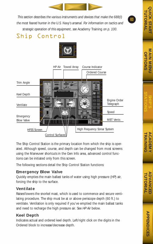
This section describes the various instruments and devices that make the 688(I)
the most feared hunter in the U.S. Navy’s arsenal. For information on tactics and
strategic operation of this equipment, see Academy Training on p. 100.
Ship Control
The Ship Control Station is the primary location from which the ship is oper-ated. Although speed, course, and depth can be changed from most screensusing the Maneuver shortcuts in the Gen Info area, advanced control func-tions can be initiated only from this screen.
The following sections detail the Ship Control Station functions:
Emergency Blow ValveQuickly empties the main ballast tanks of water using high pressure (HP) air,forcing the ship to the surface.
VentilateRaises/lowers the snorkel mast, which is used to commence and secure venti-lating procedure. The ship must be at or above periscope depth (60 ft.) toventilate. Ventilation is only required if you’ve emptied the main ballast tanksand need to recharge the high pressure air. See HP Air below.
Keel DepthIndicates actual and ordered keel depth. Left/right click on the digits in theOrdered block to increase/decrease depth.
63
MA
IN M
ENU
OP
TIO
NS
AC
AD
EMY
TR
AIN
ING
AD
VA
NC
EDT
UT
OR
IAL
AP
PEN
DIC
ESQ
UIC
K STA
RT
TU
TO
RIA
LSH
IP’S
STAT
ION
S
High Frequency Sonar System
Trim Angle
Keel Depth
Ventilate
EmergencyBlow Valve
Ordered Course
Course IndicatorTowed ArrayHP Air
HFSS Screen
Control Surfaces
Engine OrderTelegraph
Speed
MBT Vents
688(i)/AttackSubChptr3 5/6/98 10:46 AM Page 1
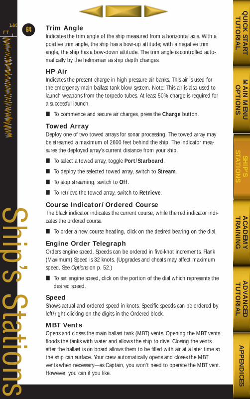
Trim AngleIndicates the trim angle of the ship measured from a horizontal axis. With apositive trim angle, the ship has a bow-up attitude; with a negative trimangle, the ship has a bow-down attitude. The trim angle is controlled auto-matically by the helmsman as ship depth changes.
HP AirIndicates the present charge in high pressure air banks. This air is used forthe emergency main ballast tank blow system. Note: This air is also used tolaunch weapons from the torpedo tubes. At least 50% charge is required fora successful launch.
■ To commence and secure air charges, press the Charge button.
Towed ArrayDeploy one of two towed arrays for sonar processing. The towed array maybe streamed a maximum of 2600 feet behind the ship. The indicator mea-sures the deployed array’s current distance from your ship.
■ To select a towed array, toggle Port/Starboard.
■ To deploy the selected towed array, switch to Stream.
■ To stop streaming, switch to Off.
■ To retrieve the towed array, switch to Retrieve.
Course Indicator/Ordered CourseThe black indicator indicates the current course, while the red indicator indi-cates the ordered course.
■ To order a new course heading, click on the desired bearing on the dial.
Engine Order TelegraphOrders engine speed. Speeds can be ordered in five-knot increments. Flank(Maximum) Speed is 32 knots. (Upgrades and cheats may affect maximumspeed. See Options on p. 52.)
■ To set engine speed, click on the portion of the dial which represents thedesired speed.
SpeedShows actual and ordered speed in knots. Specific speeds can be ordered byleft/right-clicking on the digits in the Ordered block.
MBT VentsOpens and closes the main ballast tank (MBT) vents. Opening the MBT ventsfloods the tanks with water and allows the ship to dive. Closing the ventsafter the ballast is on board allows them to be filled with air at a later time sothe ship can surface. Your crew automatically opens and closes the MBTvents when necessary—as Captain, you won’t need to operate the MBT vent.However, you can if you like.
FT
180
64
Ship’s Stations
MA
IN M
ENU
OP
TIO
NS
AC
AD
EMY
TR
AIN
ING
AD
VA
NC
EDT
UT
OR
IAL
AP
PEN
DIC
ESQ
UIC
K STA
RT
TU
TO
RIA
LSH
IP’S
STAT
ION
S
688(i)/AttackSubChptr3 5/6/98 10:46 AM Page 2
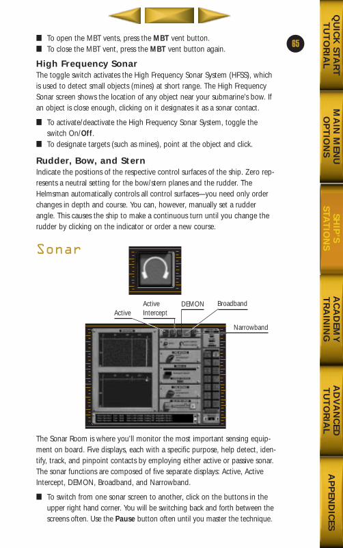
■ To open the MBT vents, press the MBT vent button.■ To close the MBT vent, press the MBT vent button again.
High Frequency SonarThe toggle switch activates the High Frequency Sonar System (HFSS), whichis used to detect small objects (mines) at short range. The High FrequencySonar screen shows the location of any object near your submarine’s bow. Ifan object is close enough, clicking on it designates it as a sonar contact.
■ To activate/deactivate the High Frequency Sonar System, toggle theswitch On/Off.
■ To designate targets (such as mines), point at the object and click.
Rudder, Bow, and SternIndicate the positions of the respective control surfaces of the ship. Zero rep-resents a neutral setting for the bow/stern planes and the rudder. TheHelmsman automatically controls all control surfaces—you need only orderchanges in depth and course. You can, however, manually set a rudderangle. This causes the ship to make a continuous turn until you change therudder by clicking on the indicator or order a new course.
Sonar
The Sonar Room is where you’ll monitor the most important sensing equip-ment on board. Five displays, each with a specific purpose, help detect, iden-tify, track, and pinpoint contacts by employing either active or passive sonar.The sonar functions are composed of five separate displays: Active, ActiveIntercept, DEMON, Broadband, and Narrowband.
■ To switch from one sonar screen to another, click on the buttons in theupper right hand corner. You will be switching back and forth between thescreens often. Use the Pause button often until you master the technique.
65
MA
IN M
ENU
OP
TIO
NS
AC
AD
EMY
TR
AIN
ING
AD
VA
NC
EDT
UT
OR
IAL
AP
PEN
DIC
ESQ
UIC
K STA
RT
TU
TO
RIA
LSH
IP’S
STAT
ION
S
ActiveActiveIntercept
DEMON
Narrowband
Broadband
688(i)/AttackSubChptr3 5/6/98 10:46 AM Page 3
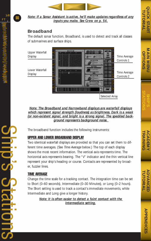
Note: If a Sonar Assistant is active, he’ll make updates regardless of anyinputs you make. See Crew on p. 54.
BroadbandThe default sonar function, Broadband, is used to detect and track all classesof submarines and surface ships.
Note: The Broadband and Narrowband displays are waterfall displayswhich represent signal strength (loudness) as brightness. Dark is a weak(or non-existent signal, and bright is a strong signal. The speckled back-
ground represents background noise.
The broadband function includes the following instruments:
UPPER AND LOWER BROADBAND DISPLAYTwo identical waterfall displays are provided so that you can set them to dif-ferent time averages. (See Time Average below.) The top of each displayshows the most recent information. The vertical axis represents time. Thehorizontal axis represents bearing. The “V” indicator and the thin vertical linerepresent your ship’s heading or course. Contacts are represented by broad-er, fuzzier lines.
TIME AVERAGEChange the time scale for a tracking contact. The integration time can be setto Short (0–60 seconds), Intermediate (0–30 Minutes), or Long (0–2 hours).The Short setting is used to track a contact’s immediate movements, whileIntermediate and Long give a longer history.
Note: It is often easier to detect a faint contact with the Intermediate setting.
FT
180
66
Ship’s Stations
MA
IN M
ENU
OP
TIO
NS
AC
AD
EMY
TR
AIN
ING
AD
VA
NC
EDT
UT
OR
IAL
AP
PEN
DIC
ESQ
UIC
K STA
RT
TU
TO
RIA
LSH
IP’S
STAT
ION
S
Upper WaterfallDisplay
Lower WaterfallDisplay
Time AverageControls 1
Time AverageControls 2
Selected Array
688(i)/AttackSubChptr3 5/6/98 10:46 AM Page 4
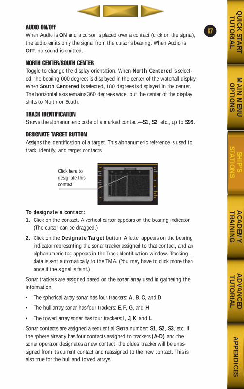
AUDIO ON/OFFWhen Audio is ON and a cursor is placed over a contact (click on the signal),the audio emits only the signal from the cursor’s bearing. When Audio isOFF, no sound is emitted.
NORTH CENTER/SOUTH CENTERToggle to change the display orientation. When North Centered is select-ed, the bearing 000 degrees is displayed in the center of the waterfall display.When South Centered is selected, 180 degrees is displayed in the center.The horizontal axis remains 360 degrees wide, but the center of the displayshifts to North or South.
TRACK IDENTIFICATIONShows the alphanumeric code of a marked contact—S1, S2, etc., up to S99.
DESIGNATE TARGET BUTTONAssigns the identification of a target. This alphanumeric reference is used totrack, identify, and target contacts.
To designate a contact:1. Click on the contact. A vertical cursor appears on the bearing indicator.
(The cursor can be dragged.)
2. Click on the Designate Target button. A letter appears on the bearingindicator representing the sonar tracker assigned to that contact, and analphanumeric tag appears in the Track Identification window. Trackingdata is sent automatically to the TMA. (You may have to click more thanonce if the signal is faint.)
Sonar trackers are assigned based on the sonar array used in gathering theinformation.
• The spherical array sonar has four trackers: A, B, C, and D
• The hull array sonar has four trackers: E, F, G, and H
• The towed array sonar has four trackers: I, J, K, and L
Sonar contacts are assigned a sequential Sierra number: S1, S2, S3, etc. Ifthe sphere already has four contacts assigned to trackers (A-D) and thesonar operator designates a new contact, the oldest tracker will be unas-signed from its current contact and reassigned to the new contact. This isalso true for the hull and towed arrays.
67
MA
IN M
ENU
OP
TIO
NS
AC
AD
EMY
TR
AIN
ING
AD
VA
NC
EDT
UT
OR
IAL
AP
PEN
DIC
ESQ
UIC
K STA
RT
TU
TO
RIA
LSH
IP’S
STAT
ION
SClick here to designate thiscontact.
688(i)/AttackSubChptr3 5/6/98 10:46 AM Page 5
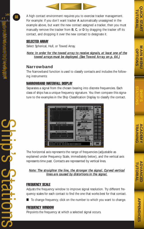
FT
180 A high contact environment requires you to exercise tracker management.For example: if you don’t want tracker A automatically unassigned in theexample above, but want the new contact assigned a tracker, then you mustmanually remove the tracker from B, C, or D by dragging the tracker off itscontact, and dropping it over the new contact to designate it.
SELECTED ARRAYSelect Spherical, Hull, or Towed Array.
Note: In order for the towed array to receive signals, at least one of thetowed arrays must be deployed. (See Towed Array on p. 64.)
NarrowbandThe Narrowband function is used to classify contacts and includes the follow-ing instruments:
NARROWBAND WATERFALL DISPLAYSeparates a signal from the chosen bearing into discrete frequencies. Eachclass of ships has a unique frequency signature. You then compare this signa-ture to the examples in the Ship Classification Display to classify the contact.
The horizontal axis represents the range of frequencies (adjustable asexplained under Frequency Scale, immediately below), and the vertical axisrepresents time past. Contacts are represented by vertical lines.
Note: The straighter the line, the stronger the signal. Curved verticallines are caused by distortions in the signal.
FREQUENCY SCALEAdjusts the frequency window to improve signal resolution. Try different fre-quency scales for each contact to find the one that works best for that contact.
■ To change frequency, click on the number to which you want to change.
FREQUENCY WINDOWPinpoints the frequency at which a selected signal occurs.
Ship’s Stations
68
MA
IN M
ENU
OP
TIO
NS
AC
AD
EMY
TR
AIN
ING
AD
VA
NC
EDT
UT
OR
IAL
AP
PEN
DIC
ESQ
UIC
K STA
RT
TU
TO
RIA
LSH
IP’S
STAT
ION
S
688(i)/AttackSubChptr3 5/6/98 10:46 AM Page 6
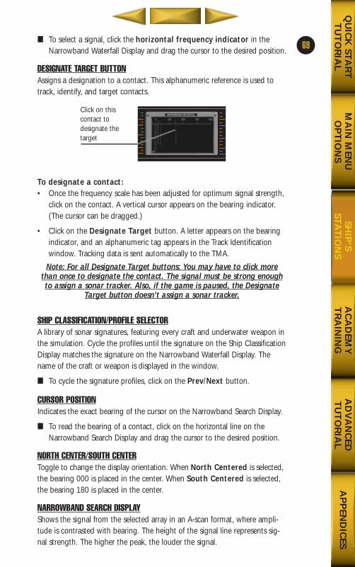
■ To select a signal, click the horizontal frequency indicator in theNarrowband Waterfall Display and drag the cursor to the desired position.
DESIGNATE TARGET BUTTONAssigns a designation to a contact. This alphanumeric reference is used totrack, identify, and target contacts.
To designate a contact:• Once the frequency scale has been adjusted for optimum signal strength,
click on the contact. A vertical cursor appears on the bearing indicator.(The cursor can be dragged.)
• Click on the Designate Target button. A letter appears on the bearingindicator, and an alphanumeric tag appears in the Track Identificationwindow. Tracking data is sent automatically to the TMA.
Note: For all Designate Target buttons: You may have to click morethan once to designate the contact. The signal must be strong enoughto assign a sonar tracker. Also, if the game is paused, the Designate
Target button doesn’t assign a sonar tracker.
SHIP CLASSIFICATION/PROFILE SELECTORA library of sonar signatures, featuring every craft and underwater weapon inthe simulation. Cycle the profiles until the signature on the Ship ClassificationDisplay matches the signature on the Narrowband Waterfall Display. Thename of the craft or weapon is displayed in the window.
■ To cycle the signature profiles, click on the Prev/Next button.
CURSOR POSITIONIndicates the exact bearing of the cursor on the Narrowband Search Display.
■ To read the bearing of a contact, click on the horizontal line on theNarrowband Search Display and drag the cursor to the desired position.
NORTH CENTER/SOUTH CENTERToggle to change the display orientation. When North Centered is selected,the bearing 000 is placed in the center. When South Centered is selected,the bearing 180 is placed in the center.
NARROWBAND SEARCH DISPLAYShows the signal from the selected array in an A-scan format, where ampli-tude is contrasted with bearing. The height of the signal line represents sig-nal strength. The higher the peak, the louder the signal.
69
MA
IN M
ENU
OP
TIO
NS
AC
AD
EMY
TR
AIN
ING
AD
VA
NC
EDT
UT
OR
IAL
AP
PEN
DIC
ESQ
UIC
K STA
RT
TU
TO
RIA
LSH
IP’S
STAT
ION
S
Click on thiscontact to designate thetarget
688(i)/AttackSubChptr3 5/6/98 10:46 AM Page 7
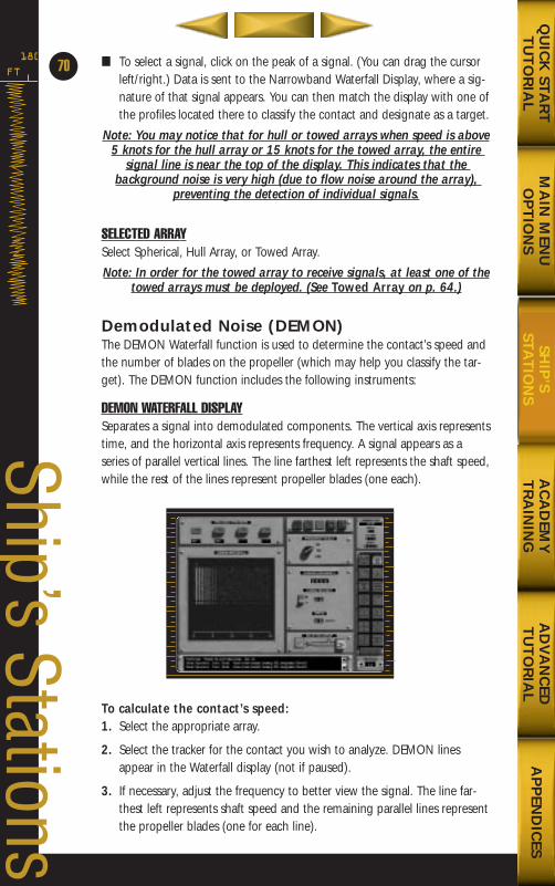
■ To select a signal, click on the peak of a signal. (You can drag the cursorleft/right.) Data is sent to the Narrowband Waterfall Display, where a sig-nature of that signal appears. You can then match the display with one ofthe profiles located there to classify the contact and designate as a target.
Note: You may notice that for hull or towed arrays when speed is above5 knots for the hull array or 15 knots for the towed array, the entire
signal line is near the top of the display. This indicates that the background noise is very high (due to flow noise around the array),
preventing the detection of individual signals.
SELECTED ARRAYSelect Spherical, Hull Array, or Towed Array.
Note: In order for the towed array to receive signals, at least one of thetowed arrays must be deployed. (See Towed Array on p. 64.)
Demodulated Noise (DEMON)The DEMON Waterfall function is used to determine the contact’s speed andthe number of blades on the propeller (which may help you classify the tar-get). The DEMON function includes the following instruments:
DEMON WATERFALL DISPLAYSeparates a signal into demodulated components. The vertical axis representstime, and the horizontal axis represents frequency. A signal appears as aseries of parallel vertical lines. The line farthest left represents the shaft speed,while the rest of the lines represent propeller blades (one each).
To calculate the contact’s speed:1. Select the appropriate array.
2. Select the tracker for the contact you wish to analyze. DEMON linesappear in the Waterfall display (not if paused).
3. If necessary, adjust the frequency to better view the signal. The line far-thest left represents shaft speed and the remaining parallel lines representthe propeller blades (one for each line).
FT
180
Ship’s Stations
70
MA
IN M
ENU
OP
TIO
NS
AC
AD
EMY
TR
AIN
ING
AD
VA
NC
EDT
UT
OR
IAL
AP
PEN
DIC
ESQ
UIC
K STA
RT
TU
TO
RIA
LSH
IP’S
STAT
ION
S
688(i)/AttackSubChptr3 5/6/98 10:46 AM Page 8
4. Place the cursor over the line farthest left.
5. Enter the appropriate turns per knot number. This depends on ship typeas determined by classification in the Narrowband Waterfall Display, ESM,or periscope. (See the informational file on the ship’s class in the On-lineinformation library to determine turns per knot for the given vessel.)The speed of the target appears in the SPEED Display.
AVAILABLE TRACKERSRepresent selected targets and the source of data displayed on the DEMONWaterfall.
■ To select a data source, click on the tracker whose alphanumeric designa-tion matches the contact you wish to monitor.
Note: In order for the TRACKERS to function, a contact must have beendesignated in the BROADBAND display.
FREQUENCY SCALEAdjusts the frequency window to improve signal resolution.
• To change frequency, click on the number to which you want to change.
CURSOR FREQUENCYIndicates the Waterfall Display cursor’s precise frequency according to thehorizontal frequency indicator.
■ To pinpoint the frequency of a signal, click on the signal. The cursorappears just above the horizontal line at the top of the DEMON Waterfalldisplay. If necessary, drag the cursor left or right for precise placement.
TURNS PER KNOTRepresents the number of propeller shaft rotations per knot of speed for agiven vessel. Enter the turns per knot of the ship you are tracking to help calculate the ship’s speed. Turns per knot for all classes of craft are provided in the Online Information library. Check the file for the ship you’re tracking,then enter the number.
■ To enter turns per knot, click on the switch to the left of the digital display until the appropriate number appears.
SPEEDRepresents the speed of the target in knots. Once you have the correct turns per knot, and the cursor over the current signal, this will display the current speed of the contact.
SELECTED ARRAYSelect Spherical or Towed Array.
71
MA
IN M
ENU
OP
TIO
NS
AC
AD
EMY
TR
AIN
ING
AD
VA
NC
EDT
UT
OR
IAL
AP
PEN
DIC
ESQ
UIC
K STA
RT
TU
TO
RIA
LSH
IP’S
STAT
ION
S
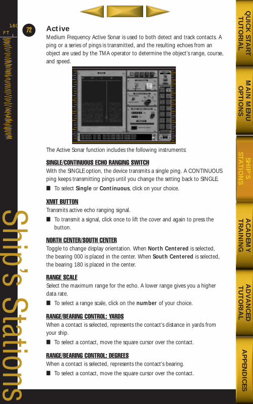
ActiveMedium Frequency Active Sonar is used to both detect and track contacts. Aping or a series of pings is transmitted, and the resulting echoes from anobject are used by the TMA operator to determine the object’s range, course,and speed.
The Active Sonar function includes the following instruments:
SINGLE/CONTINUOUS ECHO RANGING SWITCHWith the SINGLE option, the device transmits a single ping. A CONTINUOUSping keeps transmitting pings until you change the setting back to SINGLE.
■ To select Single or Continuous, click on your choice.
XMIT BUTTONTransmits active echo ranging signal.
■ To transmit a signal, click once to lift the cover and again to press thebutton.
NORTH CENTER/SOUTH CENTERToggle to change display orientation. When North Centered is selected,the bearing 000 is placed in the center. When South Centered is selected,the bearing 180 is placed in the center.
RANGE SCALESelect the maximum range for the echo. A lower range gives you a higherdata rate.
■ To select a range scale, click on the number of your choice.
RANGE/BEARING CONTROL: YARDSWhen a contact is selected, represents the contact’s distance in yards fromyour ship.
■ To select a contact, move the square cursor over the contact.
RANGE/BEARING CONTROL: DEGREESWhen a contact is selected, represents the contact’s bearing.
■ To select a contact, move the square cursor over the contact.
FT
180
Ship’s Stations
72
MA
IN M
ENU
OP
TIO
NS
AC
AD
EMY
TR
AIN
ING
AD
VA
NC
EDT
UT
OR
IAL
AP
PEN
DIC
ESQ
UIC
K STA
RT
TU
TO
RIA
LSH
IP’S
STAT
ION
S
688(i)/AttackSubChptr3 5/6/98 10:46 AM Page 10
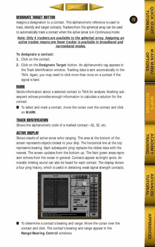
DESIGNATE TARGET BUTTONAssigns a designation to a contact. This alphanumeric reference is used totrack, identify and target contacts. Trackers from the spherical array can be usedto automatically track a contact when the active sonar is in Continuous mode.
Note: Only 4 trackers are available to the spherical array. Assigning anactive tracker means one fewer tracker is available in broadband and
narrowband modes.
To designate a contact:1. Click on the contact.
2. Click on the Designate Target button. An alphanumeric tag appears inthe Track Identification window. Tracking data is sent automatically to theTMA. Again, you may need to click more than once on a contact if thesignal is faint.
MARKSends information about a selected contact to TMA for analysis. Marking sub-sequent echoes provides enough information to calculate a solution for thecontact.
■ To select and mark a contact, move the cursor over the contact and clickon MARK.
TRACK IDENTIFICATIONShows the alphanumeric code of a marked contact—S1, S2, etc.
ACTIVE DISPLAYShows results of active sonar echo ranging. The area at the bottom of thescreen represents objects closest to your ship. The horizontal line at the toprepresents bearing. Each subsequent ping replaces the oldest data with thenewest. The screen updates from the bottom up. The faint green areas repre-sent echoes from the ocean in general. Contacts appear as bright spots. Anmetallic tinkling sound can also be heard for each contact. The display showsa four ping history, which is useful in detecting weak signal strength contacts.
■ To determine a contact’s bearing and range: Move the cursor over thecontact and click. The contact’s bearing and range appear in theRange/Bearing Control windows.
73
MA
IN M
ENU
OP
TIO
NS
AC
AD
EMY
TR
AIN
ING
AD
VA
NC
EDT
UT
OR
IAL
AP
PEN
DIC
ESQ
UIC
K STA
RT
TU
TO
RIA
LSH
IP’S
STAT
ION
S
688(i)/AttackSubChptr3 5/6/98 10:46 AM Page 11
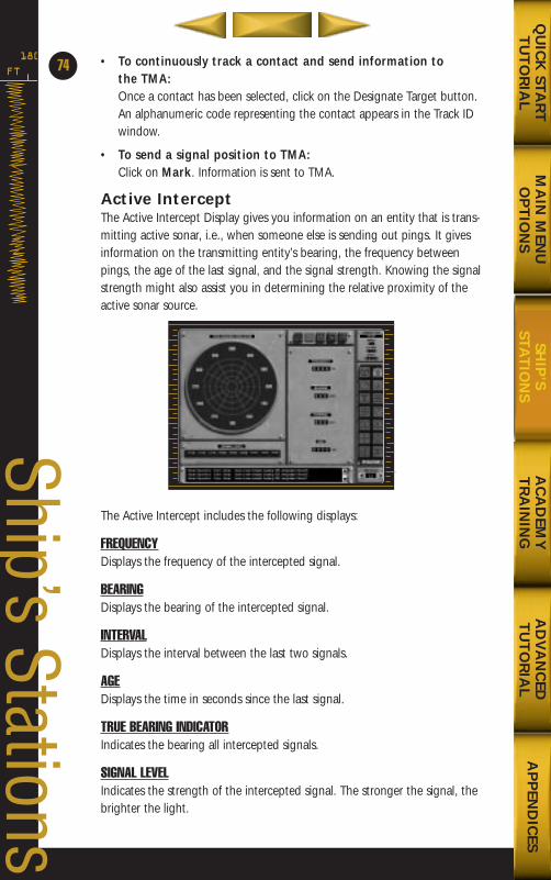
• To continuously track a contact and send information to the TMA:Once a contact has been selected, click on the Designate Target button.An alphanumeric code representing the contact appears in the Track IDwindow.
• To send a signal position to TMA:Click on Mark. Information is sent to TMA.
Active InterceptThe Active Intercept Display gives you information on an entity that is trans-mitting active sonar, i.e., when someone else is sending out pings. It givesinformation on the transmitting entity’s bearing, the frequency betweenpings, the age of the last signal, and the signal strength. Knowing the signalstrength might also assist you in determining the relative proximity of theactive sonar source.
The Active Intercept includes the following displays:
FREQUENCYDisplays the frequency of the intercepted signal.
BEARINGDisplays the bearing of the intercepted signal.
INTERVALDisplays the interval between the last two signals.
AGEDisplays the time in seconds since the last signal.
TRUE BEARING INDICATORIndicates the bearing all intercepted signals.
SIGNAL LEVELIndicates the strength of the intercepted signal. The stronger the signal, thebrighter the light.
FT
180
74
Ship’s Stations
MA
IN M
ENU
OP
TIO
NS
AC
AD
EMY
TR
AIN
ING
AD
VA
NC
EDT
UT
OR
IAL
AP
PEN
DIC
ESQ
UIC
K STA
RT
TU
TO
RIA
LSH
IP’S
STAT
ION
S
688(i)/AttackSubChptr3 5/6/98 10:46 AM Page 12
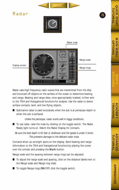
Radar
Radar uses high frequency radio waves that are transmitted from the shipand bounced off objects on the surface of the ocean to determine bearingand range. Bearing and range data, once appropriately marked, is then sentto the TMA and Navigational functions for analysis. Use the radar to detectsurface contacts, land, and low-flying objects.
■ Submarine radar is used exclusively when the sub is at periscope depth orwhen the sub is surfaced.
Unlike the periscope, radar works well in foggy conditions.
■ To use radar, raise the mast by clicking on the toggle switch. The RadarReady light turns on. Watch the Radar Display for contacts.
Be sure the keel depth is 60 feet or shallower and the speed is under 5 knots.This prevents damage to the delicate radar mast.
Contacts show up as bright spots on the display. Send bearing and rangeinformation to the TMA and Navigational functions by placing the cursorover the contact and pressing the Mark button.
Range scale and the spacing between range rings can be adjusted.
■ To adjust the range scale and spacing, click on the distance labels next tothe Range scale and Range ring dials.
■ To toggle Range rings ON/OFF, click the toggle switch.
75
MA
IN M
ENU
OP
TIO
NS
AC
AD
EMY
TR
AIN
ING
AD
VA
NC
EDT
UT
OR
IAL
AP
PEN
DIC
ESQ
UIC
K STA
RT
TU
TO
RIA
LSH
IP’S
STAT
ION
S
Display screen
Radar mast
Range scale
Range rings
688(i)/AttackSubChptr3 5/6/98 10:46 AM Page 13
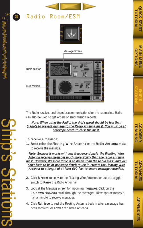
Radio Room/ESM
The Radio receives and decodes communications for the submarine. Radiocan also be used to get orders or send mission reports.
Note: When using the Radio, the ship’s speed should be less than 5 knots to prevent damage to the Radio Antenna mast. You must be at
periscope depth to raise the mast.
To receive a message:1. Select either the Floating Wire Antenna or the Radio Antenna mast
to receive the message.
Note: Because it works with low frequency signals, the Floating WireAntenna receives messages much more slowly than the radio antenna
mast. However, it’s more difficult to detect than the Radio mast, and youdon’t have to be at periscope depth to use it. Stream the Floating WireAntenna to a length of at least 600 feet to ensure message reception.
2. Click Stream to activate the Floating Wire Antenna, or use the toggleswitch to Raise the Radio Antenna.
3. Look at the Message screen for incoming messages. Click on theup/down arrows to scroll through the messages. Allow approximately ahalf a minute to receive messages.
4. Click Retrieve to reel the Floating Antenna back in after a message hasbeen received, or Lower the Radio Antenna.
FT
180
76
Ship’s Stations
Radio section
ESM section
Message Screen
MA
IN M
ENU
OP
TIO
NS
AC
AD
EMY
TR
AIN
ING
AD
VA
NC
EDT
UT
OR
IAL
AP
PEN
DIC
ESQ
UIC
K STA
RT
TU
TO
RIA
LSH
IP’S
STAT
ION
S
688(i)/AttackSubChptr3 5/6/98 10:46 AM Page 14
MA
IN M
ENU
OP
TIO
NS
AC
AD
EMY
TR
AIN
ING
AD
VA
NC
EDT
UT
OR
IAL
AP
PEN
DIC
ESQ
UIC
K STA
RT
TU
TO
RIA
LSH
IP’S
STAT
ION
S
77To transmit a report at the end of a mission:1. Click on the Transmit Mission Report button to lift the cover.
2. Click the button again to send the report.
Note: This signals the completion of a mission. You are debriefed andyour performance assessed. Don’t transmit a report unless you have
completed the mission.
To transmit a message: (Available only in a Multiplayer game.)1. Click the small text box just above the message screen
2. Type a message.
3. Click the Send Message button to broadcast the message to all players.
Note: You don’t need to be at a periscope depth or have the radioantenna raised to send messages to other players.
ESMElectronic Surveillance Measures (ESM) is a passive system used to detectradar and radio transmissions. When the antenna is raised above the level ofthe water, it can detect and indicate the direction and signal level of radio orradar transmissions from other ships.
To use ESM:
1. To activate the ESM system, raise the ESM antenna by clicking on thetoggle switch. Watch the display screen for contact data.
Note: As with the Radio Antenna mast, only raise and lower the ESMantenna at periscope depth and keep your speed under 5 knots.
2. Click on the contact image to determine contact bearing and to view thesource of the signal (e.g., Grisha, Helix, etc.). The source information isautomatically determined from the wavelength of the transmission.
3. The ESM Indicator lights indicate the strength of the signal and ascendfrom green to red as the signal grows in strength.
4. To send the bearing data to the TMA function, press the Mark button.
688(i)/AttackSubChptr3 5/6/98 10:46 AM Page 15
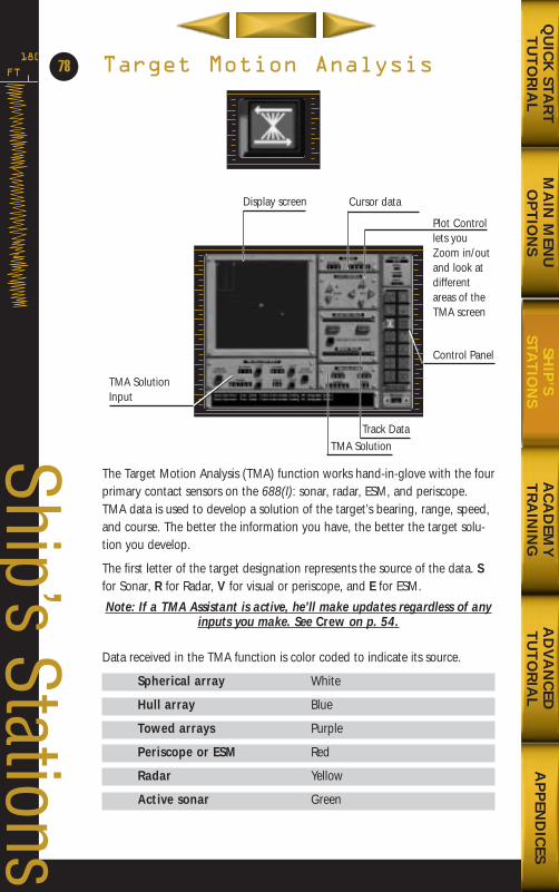
Target Motion Analysis
The Target Motion Analysis (TMA) function works hand-in-glove with the fourprimary contact sensors on the 688(I): sonar, radar, ESM, and periscope.TMA data is used to develop a solution of the target’s bearing, range, speed,and course. The better the information you have, the better the target solu-tion you develop.
The first letter of the target designation represents the source of the data. Sfor Sonar, R for Radar, V for visual or periscope, and E for ESM.
Note: If a TMA Assistant is active, he’ll make updates regardless of anyinputs you make. See Crew on p. 54.
Data received in the TMA function is color coded to indicate its source.
Spherical array White
Hull array Blue
Towed arrays Purple
Periscope or ESM Red
Radar Yellow
Active sonar Green
FT
180
Ship’s Stations
78
Track Data
TMA SolutionInput
Plot Controllets youZoom in/outand look atdifferentareas of theTMA screen
Control Panel
Cursor dataDisplay screen
TMA Solution
MA
IN M
ENU
OP
TIO
NS
AC
AD
EMY
TR
AIN
ING
AD
VA
NC
EDT
UT
OR
IAL
AP
PEN
DIC
ESQ
UIC
K STA
RT
TU
TO
RIA
LSH
IP’S
STAT
ION
S
688(i)/AttackSubChptr3 5/6/98 10:46 AM Page 16

MA
IN M
ENU
OP
TIO
NS
AC
AD
EMY
TR
AIN
ING
AD
VA
NC
EDT
UT
OR
IAL
AP
PEN
DIC
ESQ
UIC
K STA
RT
TU
TO
RIA
LSH
IP’S
STAT
ION
S
To determine a target solution from Active Sonar, the Periscope,or the Radar:Data from the periscope, active sonar, and radar appear as a bearing/rangepair. If the target’s bearing and range are known at two different times, as isthe case with active sonar and radar, the solution can be found by connect-ing dots and drawing a line for course and speed.
1. Click on the Selected Track arrow to display the list of contacts.
2. Select the contact you want. A bearing line appears in the view screen.Bearing lines represent the direction to the contact at different times, asthe contact and your own ship moved. A bubble at the end of the bear-ing line indicates the target’s range at that time.
3. After a short interval, return to the active sonar, periscope, or radar func-tion (whichever you are using) and mark the contact by clicking theMark button again. Continue to Mark the contact at different intervals toaccumulate several bearing lines. Toggle back and forth between the TMAand your chosen sensor.
4. Using the Plot Control, pan around the view screen to get a clear view.
5. Place the back of the ruler in the bubble of the oldest bearing/range line.Place the front tick mark (short line across the ruler) in the bubble of thenewest bearing/range line.
6. Look at the tick marks on the ruler. They represent the estimated positionof the contact at the time the respective bearing was sent. The tick marksshould match approximately the bearing lines.
7. The dot stack in the upper left corner is a graphical representation of theerror between the tick marks and the bearing lines. They represent theerror between the user’s solution, as represented by the ruler, and theactual logical solution. The closer the dot stack is to the center verticalline, the better the solution.
79
Dot stack
Ruler
Tick mark
Your shipBearing lines
688(i)/AttackSubChptr3 5/6/98 10:46 AM Page 17
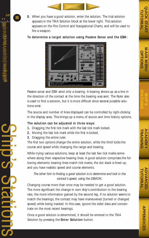
8. When you have a good solution, enter the solution. The trial solutionappears in the TMA Solution block at the lower right. This solutionappears on the Fire Control and Navigational Charts, and will be used tofire a weapon.
To determine a target solution using Passive Sonar and the ESM:
Passive sonar and ESM send only a bearing. A bearing shows up as a line inthe direction of the contact at the time the bearing was sent. The Ruler alsois used to find a solution, but it is more difficult since several possible solu-tions exist.
The source and number of lines displayed can be controlled by right-clickingin the display area. This brings up a menu of source and time history options.
The solution can be adjusted in three ways: 1. Dragging the first tick mark with the last tick mark locked.2. Moving the last tick mark while the first is locked. 3. Dragging the entire ruler. The first two options change the entire solution, while the third locks thecourse and speed while changing the range and bearing.
While trying various solutions, keep at least the last few tick marks some-where along their respective bearing lines. A good solution comprises the fol-lowing elements: bearing lines match tick marks, the dot stack is lined up,and you have realistic speed and course elements.
The other hint to finding a good solution is to determine and lock in the contact’s speed, using the DEMON.
Changing course more than once may be needed to get a good solution.The more significant the change in own ship’s contribution to the bearingrate, the more information gained by the second leg. If no solution seems tomatch the bearings, the contact may have maneuvered (turned or changedspeed) while being tracked. In this case, ignore the older data and concen-trate on the most recent bearings.
Once a good solution is determined, it should be entered to the TMASolution by pressing the Enter Solution button.
FT
180
80
Ship’s Stations
MA
IN M
ENU
OP
TIO
NS
AC
AD
EMY
TR
AIN
ING
AD
VA
NC
EDT
UT
OR
IAL
AP
PEN
DIC
ESQ
UIC
K STA
RT
TU
TO
RIA
LSH
IP’S
STAT
ION
S
688(i)/AttackSubChptr3 5/6/98 10:47 AM Page 18
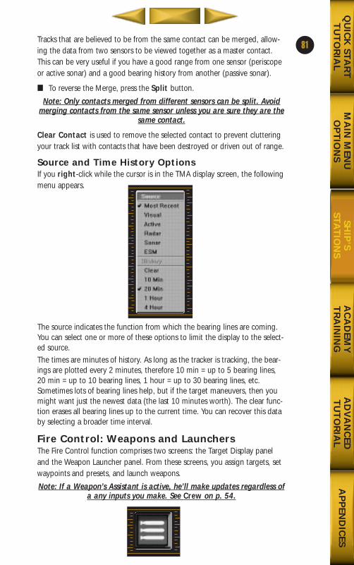
Tracks that are believed to be from the same contact can be merged, allow-ing the data from two sensors to be viewed together as a master contact.This can be very useful if you have a good range from one sensor (periscopeor active sonar) and a good bearing history from another (passive sonar).
■ To reverse the Merge, press the Split button.
Note: Only contacts merged from different sensors can be split. Avoidmerging contacts from the same sensor unless you are sure they are the
same contact.
Clear Contact is used to remove the selected contact to prevent clutteringyour track list with contacts that have been destroyed or driven out of range.
Source and Time History OptionsIf you right-click while the cursor is in the TMA display screen, the followingmenu appears.
The source indicates the function from which the bearing lines are coming.You can select one or more of these options to limit the display to the select-ed source. The times are minutes of history. As long as the tracker is tracking, the bear-ings are plotted every 2 minutes, therefore 10 min = up to 5 bearing lines,20 min = up to 10 bearing lines, 1 hour = up to 30 bearing lines, etc.Sometimes lots of bearing lines help, but if the target maneuvers, then youmight want just the newest data (the last 10 minutes worth). The clear func-tion erases all bearing lines up to the current time. You can recover this databy selecting a broader time interval.
Fire Control: Weapons and LaunchersThe Fire Control function comprises two screens: the Target Display paneland the Weapon Launcher panel. From these screens, you assign targets, setwaypoints and presets, and launch weapons.
Note: If a Weapon’s Assistant is active, he’ll make updates regardless ofa any inputs you make. See Crew on p. 54.
81
MA
IN M
ENU
OP
TIO
NS
AC
AD
EMY
TR
AIN
ING
AD
VA
NC
EDT
UT
OR
IAL
AP
PEN
DIC
ESQ
UIC
K STA
RT
TU
TO
RIA
LSH
IP’S
STAT
ION
S
688(i)/AttackSubChptr3 5/6/98 10:47 AM Page 19
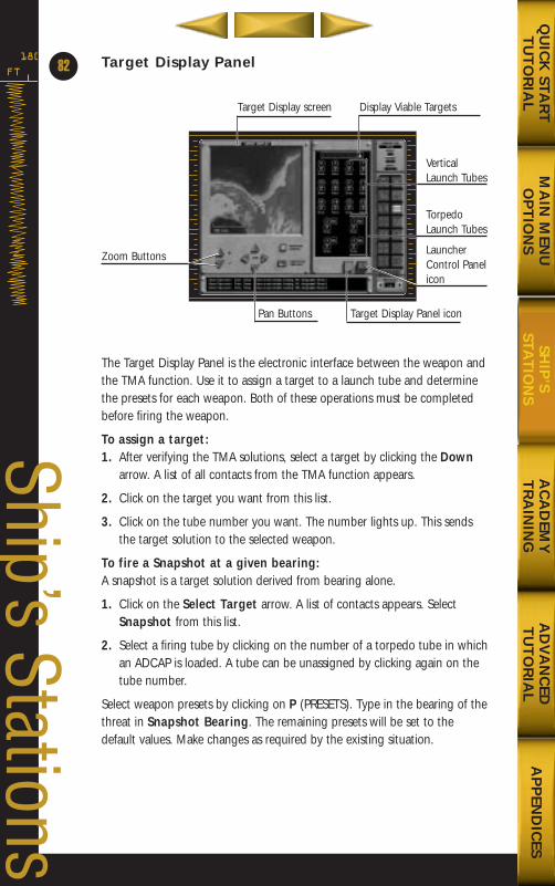
Target Display Panel
The Target Display Panel is the electronic interface between the weapon andthe TMA function. Use it to assign a target to a launch tube and determinethe presets for each weapon. Both of these operations must be completedbefore firing the weapon.
To assign a target: 1. After verifying the TMA solutions, select a target by clicking the Down
arrow. A list of all contacts from the TMA function appears.
2. Click on the target you want from this list.
3. Click on the tube number you want. The number lights up. This sendsthe target solution to the selected weapon.
To fire a Snapshot at a given bearing:A snapshot is a target solution derived from bearing alone.
1. Click on the Select Target arrow. A list of contacts appears. SelectSnapshot from this list.
2. Select a firing tube by clicking on the number of a torpedo tube in whichan ADCAP is loaded. A tube can be unassigned by clicking again on thetube number.
Select weapon presets by clicking on P (PRESETS). Type in the bearing of thethreat in Snapshot Bearing. The remaining presets will be set to thedefault values. Make changes as required by the existing situation.
FT
180
82
Ship’s Stations
MA
IN M
ENU
OP
TIO
NS
AC
AD
EMY
TR
AIN
ING
AD
VA
NC
EDT
UT
OR
IAL
AP
PEN
DIC
ESQ
UIC
K STA
RT
TU
TO
RIA
LSH
IP’S
STAT
ION
S
Target Display Panel icon
Zoom Buttons
VerticalLaunch Tubes
TorpedoLaunch Tubes
LauncherControl Panelicon
Target Display screen
Pan Buttons
Display Viable Targets
688(i)/AttackSubChptr3 5/6/98 10:47 AM Page 20
ADCAPS and HarpoonsADCAPS and Harpoons have presets. Presets give the weapon parameters tomaintain such as range, depth, etc., after it has been launched.
The presets for Harpoons are as follows:
DESTRUCT RANGE This is the range at which the missile will self-destruct if it has not encountered a target. This can be used to protect friendly and neutral forces.
SEEKER RANGE This is the range at which the missile will begin to home. It can be used to protect friendly or neutral forces that are at shorter range than the target.
SEEKER PATTERN Determines whether the area searched willbe wide or narrow. This can prevent the missile from acquiring an unintentional target that is nearby. The default values ofthe Harpoon presets: Destruct Range, 3000 nm; Seeker Turn On, 50 nm; Seeker Pattern, Wide.
To set the presets for Harpoons:
1. For the desired Torpedo tube, click P. The Preset screen appears.
2. Set the Destruct and Seeker Range, and the Seeker Pattern for theweapon (in nautical miles) by clicking on the arrows. The range is depen-dent upon your objective, and the amount of civilian traffic in the area.
3. Click Return to accept the Presets.
When ready, fire the weapon. The weapon will follow the prescribed presets.
ADCAPSADCAPS have different presets than the Harpoons. You can set set parame-ters that help protect your own ship and other friendly contacts that may bein the area and to optimize the ability of the weapon search for the target.
DEPTH (ft) Set the depth at which you want the ADCAP to travel.
CEILING (ft) Set a Ceiling for the ADCAP. For example, if you are at a certain depth, or know of friendly surface ships in the area, you canset a ceiling above which the ADCAP will not venture.
FLOOR (ft) The reverse of Ceiling, this sets a depth below which the ADCAP will not go.
83
MA
IN M
ENU
OP
TIO
NS
AC
AD
EMY
TR
AIN
ING
AD
VA
NC
EDT
UT
OR
IAL
AP
PEN
DIC
ESQ
UIC
K STA
RT
TU
TO
RIA
LSH
IP’S
STAT
ION
S
688(i)/AttackSubChptr3 5/6/98 10:47 AM Page 21
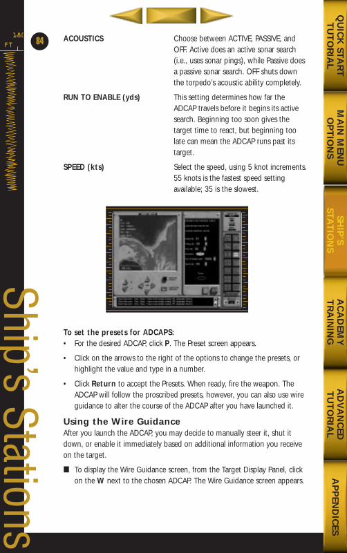
ACOUSTICS Choose between ACTIVE, PASSIVE, andOFF. Active does an active sonar search(i.e., uses sonar pings), while Passive doesa passive sonar search. OFF shuts down the torpedo’s acoustic ability completely.
RUN TO ENABLE (yds) This setting determines how far the ADCAP travels before it begins its activesearch. Beginning too soon gives the target time to react, but beginning too late can mean the ADCAP runs past its target.
SPEED (kts) Select the speed, using 5 knot increments.55 knots is the fastest speed setting available; 35 is the slowest.
To set the presets for ADCAPS:• For the desired ADCAP, click P. The Preset screen appears.
• Click on the arrows to the right of the options to change the presets, orhighlight the value and type in a number.
• Click Return to accept the Presets. When ready, fire the weapon. TheADCAP will follow the proscribed presets, however, you can also use wireguidance to alter the course of the ADCAP after you have launched it.
Using the Wire GuidanceAfter you launch the ADCAP, you may decide to manually steer it, shut itdown, or enable it immediately based on additional information you receiveon the target.
■ To display the Wire Guidance screen, from the Target Display Panel, clickon the W next to the chosen ADCAP. The Wire Guidance screen appears.
FT
180
84
Ship’s Stations
MA
IN M
ENU
OP
TIO
NS
AC
AD
EMY
TR
AIN
ING
AD
VA
NC
EDT
UT
OR
IAL
AP
PEN
DIC
ESQ
UIC
K STA
RT
TU
TO
RIA
LSH
IP’S
STAT
ION
S
688(i)/AttackSubChptr3 5/6/98 10:47 AM Page 22
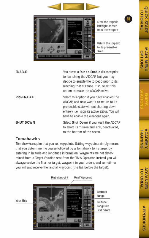
ENABLE You preset a Run to Enable distance priorto launching the ADCAP, but you may decide to enable the torpedo prior to its reaching that distance. If so, select this option to make the ADCAP active.
PRE-ENABLE Select this option if you have enabled theADCAP, and now want it to return to its pre-enable state without shutting downentirely, i.e., stop its active status. You willhave to enable the weapons again.
SHUT DOWN Select Shut Down if you want the ADCAP to abort its mission and sink, deactivated,to the bottom of the ocean.
TomahawksTomahawks require that you set waypoints. Setting waypoints simply meansthat you determine the course followed by a Tomahawk to its target byentering in latitude and longitude information. Waypoints are not deter-mined from a Target Solution sent from the TMA Operator. Instead you willalways receive the final, or target, waypoint in your orders, and sometimesyou will also receive the landfall waypoint (the last before the target).
85
MA
IN M
ENU
OP
TIO
NS
AC
AD
EMY
TR
AIN
ING
AD
VA
NC
EDT
UT
OR
IAL
AP
PEN
DIC
ESQ
UIC
K STA
RT
TU
TO
RIA
LSH
IP’S
STAT
ION
S
Steer the torpedoleft/right as seenfrom the weapon
Return the torpedoto its pre-enablestate
Your Ship
DestructRange
Latitude/LongitudeText boxes
First Waypoint Final Waypoint
688(i)/AttackSubChptr3 5/6/98 10:47 AM Page 23
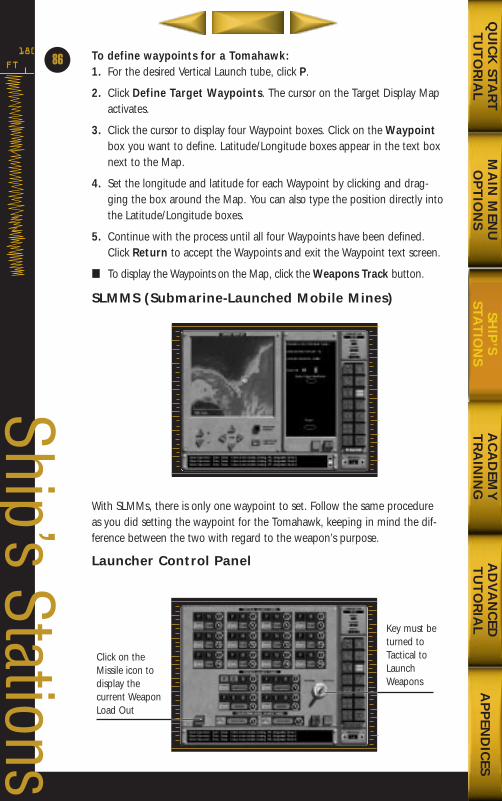
To define waypoints for a Tomahawk: 1. For the desired Vertical Launch tube, click P.
2. Click Define Target Waypoints. The cursor on the Target Display Mapactivates.
3. Click the cursor to display four Waypoint boxes. Click on the Waypointbox you want to define. Latitude/Longitude boxes appear in the text boxnext to the Map.
4. Set the longitude and latitude for each Waypoint by clicking and drag-ging the box around the Map. You can also type the position directly intothe Latitude/Longitude boxes.
5. Continue with the process until all four Waypoints have been defined.Click Return to accept the Waypoints and exit the Waypoint text screen.
■ To display the Waypoints on the Map, click the Weapons Track button.
SLMMS (Submarine-Launched Mobile Mines)
With SLMMs, there is only one waypoint to set. Follow the same procedureas you did setting the waypoint for the Tomahawk, keeping in mind the dif-ference between the two with regard to the weapon’s purpose.
Launcher Control Panel
FT
180
Ship’s Stations
86
Click on theMissile icon to display the current WeaponLoad Out
Key must beturned toTactical toLaunchWeapons
MA
IN M
ENU
OP
TIO
NS
AC
AD
EMY
TR
AIN
ING
AD
VA
NC
EDT
UT
OR
IAL
AP
PEN
DIC
ESQ
UIC
K STA
RT
TU
TO
RIA
LSH
IP’S
STAT
ION
S
688(i)/AttackSubChptr3 5/6/98 10:47 AM Page 24
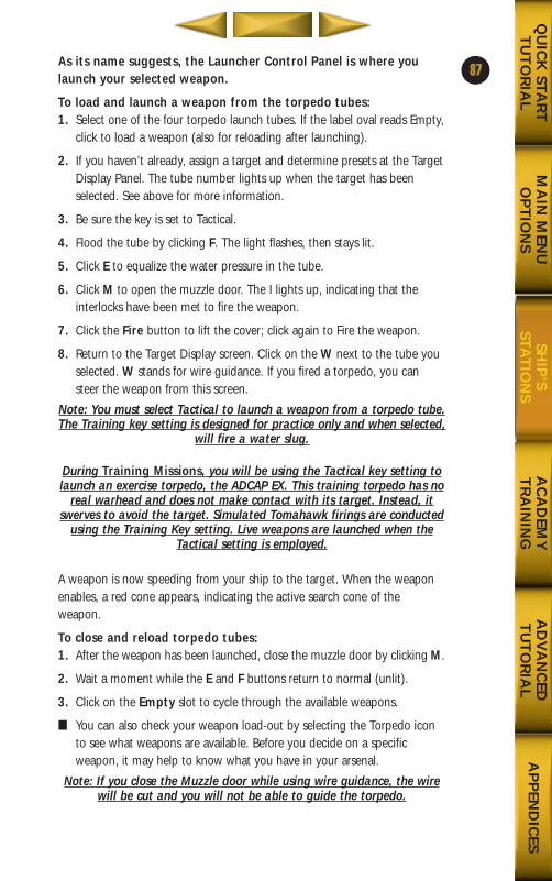
MA
IN M
ENU
OP
TIO
NS
AC
AD
EMY
TR
AIN
ING
AD
VA
NC
EDT
UT
OR
IAL
AP
PEN
DIC
ESQ
UIC
K STA
RT
TU
TO
RIA
LSH
IP’S
STAT
ION
S
As its name suggests, the Launcher Control Panel is where youlaunch your selected weapon.
To load and launch a weapon from the torpedo tubes:1. Select one of the four torpedo launch tubes. If the label oval reads Empty,
click to load a weapon (also for reloading after launching).
2. If you haven’t already, assign a target and determine presets at the TargetDisplay Panel. The tube number lights up when the target has beenselected. See above for more information.
3. Be sure the key is set to Tactical.
4. Flood the tube by clicking F. The light flashes, then stays lit.
5. Click E to equalize the water pressure in the tube.
6. Click M to open the muzzle door. The I lights up, indicating that theinterlocks have been met to fire the weapon.
7. Click the Fire button to lift the cover; click again to Fire the weapon.
8. Return to the Target Display screen. Click on the W next to the tube youselected. W stands for wire guidance. If you fired a torpedo, you cansteer the weapon from this screen.
Note: You must select Tactical to launch a weapon from a torpedo tube.The Training key setting is designed for practice only and when selected,
will fire a water slug.
During Training Missions, you will be using the Tactical key setting tolaunch an exercise torpedo, the ADCAP EX. This training torpedo has no
real warhead and does not make contact with its target. Instead, itswerves to avoid the target. Simulated Tomahawk firings are conducted
using the Training Key setting. Live weapons are launched when theTactical setting is employed.
A weapon is now speeding from your ship to the target. When the weaponenables, a red cone appears, indicating the active search cone of theweapon.
To close and reload torpedo tubes: 1. After the weapon has been launched, close the muzzle door by clicking M.
2. Wait a moment while the E and F buttons return to normal (unlit).
3. Click on the Empty slot to cycle through the available weapons.
■ You can also check your weapon load-out by selecting the Torpedo iconto see what weapons are available. Before you decide on a specificweapon, it may help to know what you have in your arsenal.
Note: If you close the Muzzle door while using wire guidance, the wirewill be cut and you will not be able to guide the torpedo.
87
688(i)/AttackSubChptr3 5/6/98 10:47 AM Page 25
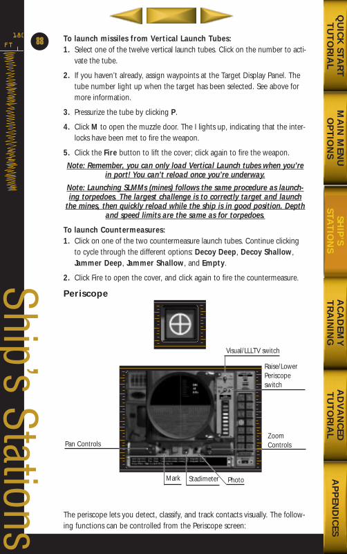
To launch missiles from Vertical Launch Tubes: 1. Select one of the twelve vertical launch tubes. Click on the number to acti-
vate the tube.
2. If you haven’t already, assign waypoints at the Target Display Panel. Thetube number light up when the target has been selected. See above formore information.
3. Pressurize the tube by clicking P.
4. Click M to open the muzzle door. The I lights up, indicating that the inter-locks have been met to fire the weapon.
5. Click the Fire button to lift the cover; click again to fire the weapon.
Note: Remember, you can only load Vertical Launch tubes when you’rein port! You can’t reload once you’re underway.
Note: Launching SLMMs (mines) follows the same procedure as launch-ing torpedoes. The largest challenge is to correctly target and launch
the mines, then quickly reload while the ship is in good position. Depthand speed limits are the same as for torpedoes.
To launch Countermeasures:1. Click on one of the two countermeasure launch tubes. Continue clicking
to cycle through the different options: Decoy Deep, Decoy Shallow,Jammer Deep, Jammer Shallow, and Empty.
2. Click Fire to open the cover, and click again to fire the countermeasure.
Periscope
The periscope lets you detect, classify, and track contacts visually. The follow-ing functions can be controlled from the Periscope screen:
FT
180
88
Ship’s Stations
MA
IN M
ENU
OP
TIO
NS
AC
AD
EMY
TR
AIN
ING
AD
VA
NC
EDT
UT
OR
IAL
AP
PEN
DIC
ESQ
UIC
K STA
RT
TU
TO
RIA
LSH
IP’S
STAT
ION
S
Stadimeter
Pan ControlsZoomControls
Mark
Visual/LLLTV switch
Photo
Raise/LowerPeriscopeswitch
688(i)/AttackSubChptr3 5/6/98 10:47 AM Page 26
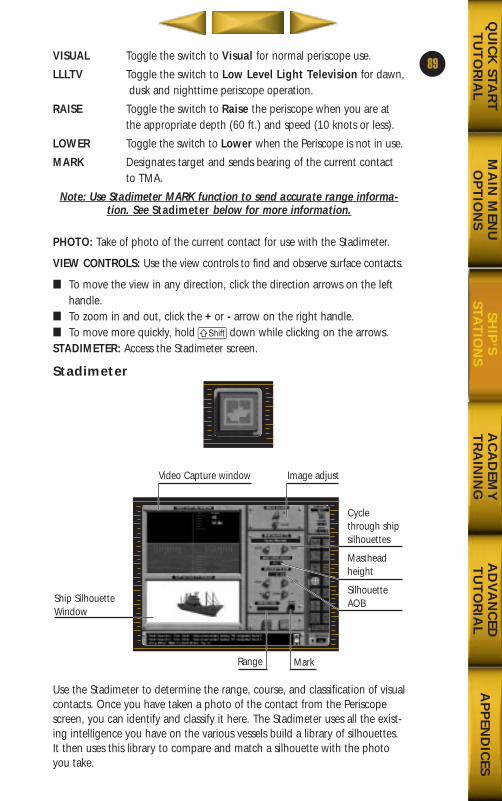
VISUAL Toggle the switch to Visual for normal periscope use.
LLLTV Toggle the switch to Low Level Light Television for dawn,dusk and nighttime periscope operation.
RAISE Toggle the switch to Raise the periscope when you are at the appropriate depth (60 ft.) and speed (10 knots or less).
LOWER Toggle the switch to Lower when the Periscope is not in use.
MARK Designates target and sends bearing of the current contact to TMA.
Note: Use Stadimeter MARK function to send accurate range informa-tion. See Stadimeter below for more information.
PHOTO: Take of photo of the current contact for use with the Stadimeter.
VIEW CONTROLS: Use the view controls to find and observe surface contacts.
■ To move the view in any direction, click the direction arrows on the lefthandle.
■ To zoom in and out, click the + or - arrow on the right handle.■ To move more quickly, hold S down while clicking on the arrows. STADIMETER: Access the Stadimeter screen.
Stadimeter
Use the Stadimeter to determine the range, course, and classification of visualcontacts. Once you have taken a photo of the contact from the Periscopescreen, you can identify and classify it here. The Stadimeter uses all the exist-ing intelligence you have on the various vessels build a library of silhouettes.It then uses this library to compare and match a silhouette with the photoyou take.
89
MA
IN M
ENU
OP
TIO
NS
AC
AD
EMY
TR
AIN
ING
AD
VA
NC
EDT
UT
OR
IAL
AP
PEN
DIC
ESQ
UIC
K STA
RT
TU
TO
RIA
LSH
IP’S
STAT
ION
S
Mark
Ship SilhouetteWindow
Cyclethrough shipsilhouettes
Mastheadheight
SilhouetteAOB
Video Capture window
Range
Image adjust
688(i)/AttackSubChptr3 5/6/98 10:47 AM Page 27
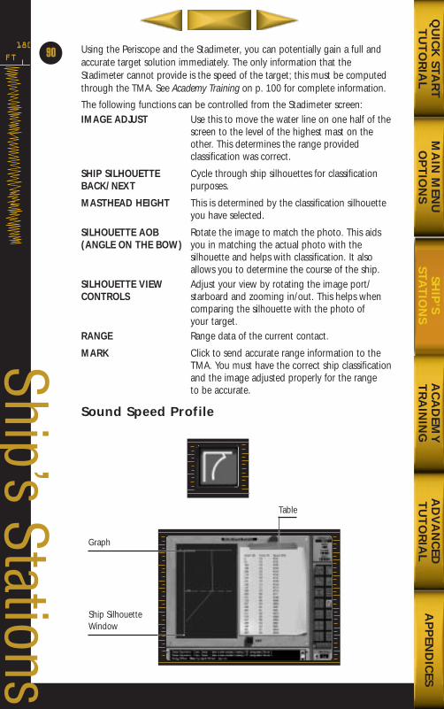
Using the Periscope and the Stadimeter, you can potentially gain a full andaccurate target solution immediately. The only information that theStadimeter cannot provide is the speed of the target; this must be computedthrough the TMA. See Academy Training on p. 100 for complete information.
The following functions can be controlled from the Stadimeter screen:IMAGE ADJUST Use this to move the water line on one half of the
screen to the level of the highest mast on the other. This determines the range provided classification was correct.
SHIP SILHOUETTE Cycle through ship silhouettes for classificationBACK/NEXT purposes.
MASTHEAD HEIGHT This is determined by the classification silhouetteyou have selected.
SILHOUETTE AOB Rotate the image to match the photo. This aids(ANGLE ON THE BOW) you in matching the actual photo with the
silhouette and helps with classification. It also allows you to determine the course of the ship.
SILHOUETTE VIEW Adjust your view by rotating the image port/CONTROLS starboard and zooming in/out. This helps when
comparing the silhouette with the photo of your target.
RANGE Range data of the current contact.
MARK Click to send accurate range information to theTMA. You must have the correct ship classificationand the image adjusted properly for the range to be accurate.
Sound Speed Profile
FT
180
90
Ship’s Stations
Ship SilhouetteWindow
Graph
Table
MA
IN M
ENU
OP
TIO
NS
AC
AD
EMY
TR
AIN
ING
AD
VA
NC
EDT
UT
OR
IAL
AP
PEN
DIC
ESQ
UIC
K STA
RT
TU
TO
RIA
LSH
IP’S
STAT
ION
S
688(i)/AttackSubChptr3 5/6/98 10:47 AM Page 28
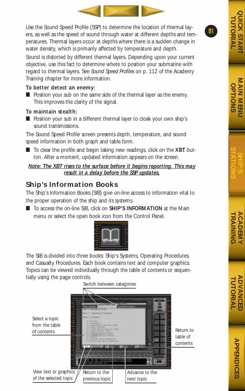
Use the Sound Speed Profile (SSP) to determine the location of thermal lay-ers, as well as the speed of sound through water at different depths and tem-peratures. Thermal layers occur at depths where there is a sudden change inwater density, which is primarily affected by temperature and depth.Sound is distorted by different thermal layers. Depending upon your currentobjective, use this fact to determine where to position your submarine withregard to thermal layers. See Sound Speed Profiles on p. 112 of the AcademyTraining chapter for more information.
To better detect an enemy: ■ Position your sub on the same side of the thermal layer as the enemy.
This improves the clarity of the signal.
To maintain stealth: ■ Position your sub in a different thermal layer to cloak your own ship’s
sound transmissions. The Sound Speed Profile screen presents depth, temperature, and soundspeed information in both graph and table form. ■ To clear the profile and begin taking new readings, click on the XBT but-
ton. After a moment, updated information appears on the screen.
Note: The XBT rises to the surface before it begins reporting. This mayresult in a delay before the SSP updates.
Ship’s Information BooksThe Ship’s Information Books (SIB) give on-line access to information vital tothe proper operation of the ship and its systems.■ To access the on-line SIB, click on SHIP’S INFORMATION at the Main
menu or select the open book icon from the Control Panel.
The SIB is divided into three books: Ship’s Systems, Operating Procedures,and Casualty Procedures. Each book contains text and computer graphics.Topics can be viewed individually through the table of contents or sequen-tially using the page controls.
91
MA
IN M
ENU
OP
TIO
NS
AC
AD
EMY
TR
AIN
ING
AD
VA
NC
EDT
UT
OR
IAL
AP
PEN
DIC
ESQ
UIC
K STA
RT
TU
TO
RIA
LSH
IP’S
STAT
ION
S
Advance to the next topic
Select a topicfrom the tableof contents Return to
table of contents
Switch between categories
Return to the previous topic
View text or graphicsof the selected topic
688(i)/AttackSubChptr3 5/6/98 10:47 AM Page 29
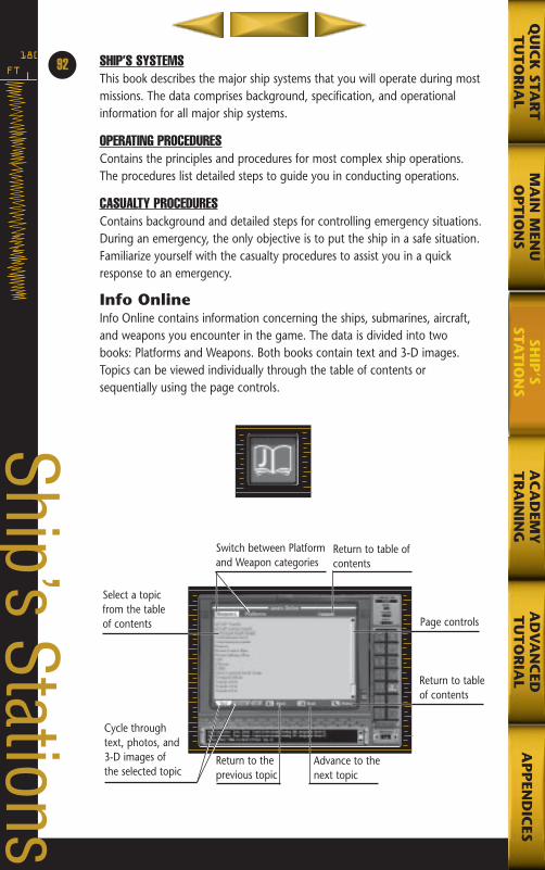
SHIP’S SYSTEMSThis book describes the major ship systems that you will operate during mostmissions. The data comprises background, specification, and operationalinformation for all major ship systems.
OPERATING PROCEDURESContains the principles and procedures for most complex ship operations.The procedures list detailed steps to guide you in conducting operations.
CASUALTY PROCEDURESContains background and detailed steps for controlling emergency situations.During an emergency, the only objective is to put the ship in a safe situation.Familiarize yourself with the casualty procedures to assist you in a quickresponse to an emergency.
Info OnlineInfo Online contains information concerning the ships, submarines, aircraft,and weapons you encounter in the game. The data is divided into twobooks: Platforms and Weapons. Both books contain text and 3-D images.Topics can be viewed individually through the table of contents or sequentially using the page controls.
FT
18092
Ship’s Stations
MA
IN M
ENU
OP
TIO
NS
AC
AD
EMY
TR
AIN
ING
AD
VA
NC
EDT
UT
OR
IAL
AP
PEN
DIC
ESQ
UIC
K STA
RT
TU
TO
RIA
LSH
IP’S
STAT
ION
S
Advance to the next topic
Select a topicfrom the tableof contents Page controls
Switch between Platform and Weapon categories
Return to the previous topic
Cycle throughtext, photos, and3-D images ofthe selected topic
Return to table ofcontents
Return to tableof contents
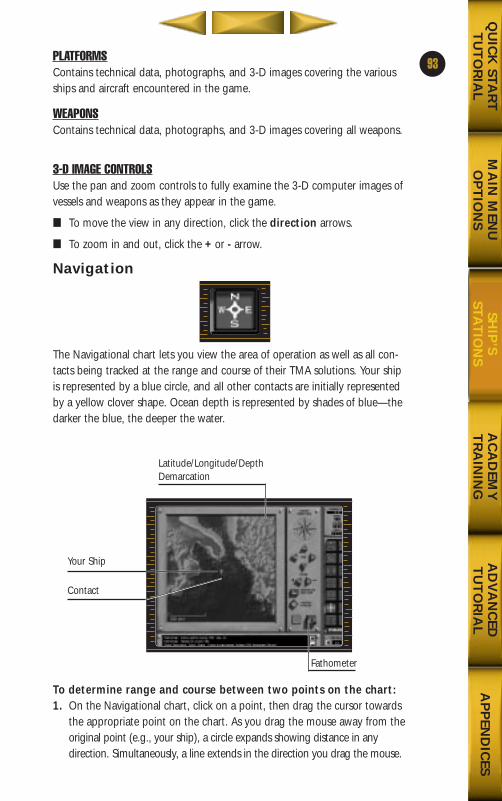
PLATFORMSContains technical data, photographs, and 3-D images covering the variousships and aircraft encountered in the game.
WEAPONSContains technical data, photographs, and 3-D images covering all weapons.
3-D IMAGE CONTROLSUse the pan and zoom controls to fully examine the 3-D computer images ofvessels and weapons as they appear in the game.
■ To move the view in any direction, click the direction arrows.
■ To zoom in and out, click the + or - arrow.
Navigation
The Navigational chart lets you view the area of operation as well as all con-tacts being tracked at the range and course of their TMA solutions. Your shipis represented by a blue circle, and all other contacts are initially representedby a yellow clover shape. Ocean depth is represented by shades of blue—thedarker the blue, the deeper the water.
To determine range and course between two points on the chart:1. On the Navigational chart, click on a point, then drag the cursor towards
the appropriate point on the chart. As you drag the mouse away from theoriginal point (e.g., your ship), a circle expands showing distance in anydirection. Simultaneously, a line extends in the direction you drag the mouse.
93
MA
IN M
ENU
OP
TIO
NS
AC
AD
EMY
TR
AIN
ING
AD
VA
NC
EDT
UT
OR
IAL
AP
PEN
DIC
ESQ
UIC
K STA
RT
TU
TO
RIA
LSH
IP’S
STAT
ION
S
Fathometer
Your Ship
Contact
Latitude/Longitude/DepthDemarcation
688(i)/AttackSubChptr3 5/6/98 10:47 AM Page 31
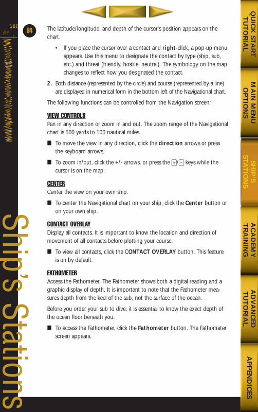
The latitude/longitude, and depth of the cursor’s position appears on thechart.
• If you place the cursor over a contact and right-click, a pop-up menuappears. Use this menu to designate the contact by type (ship, sub,etc.) and threat (friendly, hostile, neutral). The symbology on the mapchanges to reflect how you designated the contact.
2. Both distance (represented by the circle) and course (represented by a line)are displayed in numerical form in the bottom left of the Navigational chart.
The following functions can be controlled from the Navigation screen:
VIEW CONTROLSPan in any direction or zoom in and out. The zoom range of the Navigationalchart is 500 yards to 100 nautical miles.
■ To move the view in any direction, click the direction arrows or pressthe keyboard arrows.
■ To zoom in/out, click the +/- arrows, or press the +/- keys while thecursor is on the map.
CENTERCenter the view on your own ship.
■ To center the Navigational chart on your ship, click the Center button oron your own ship.
CONTACT OVERLAYDisplay all contacts. It is important to know the location and direction ofmovement of all contacts before plotting your course.
■ To view all contacts, click the CONTACT OVERLAY button. This featureis on by default.
FATHOMETERAccess the Fathometer. The Fathometer shows both a digital reading and agraphic display of depth. It is important to note that the Fathometer mea-sures depth from the keel of the sub, not the surface of the ocean.
Before you order your sub to dive, it is essential to know the exact depth ofthe ocean floor beneath you.
■ To access the Fathometer, click the Fathometer button. The Fathometerscreen appears.
FT
180
94
Ship’s Stations
MA
IN M
ENU
OP
TIO
NS
AC
AD
EMY
TR
AIN
ING
AD
VA
NC
EDT
UT
OR
IAL
AP
PEN
DIC
ESQ
UIC
K STA
RT
TU
TO
RIA
LSH
IP’S
STAT
ION
S
688(i)/AttackSubChptr3 5/6/98 10:47 AM Page 32
Fathometer
The following functions can be controlled from the Fathometer screen:
SOUNDING A digital display of the depth beneath the keel indicated in feet (FT).
DEPTH SCALE The Depth Scale is represented by the vertical numbers on the left side of the Fathometer display. If the Fathometer display is blank, it means that your current depth is outside of the currentrange and needs to be adjusted.
■ To adjust the Depth Scale, click the numbers above the Depth Scale dial.
TIME SCALE The Time Scale is represented by the horizontal numbers beneath the Fathometer display. As time passes, you may wish to adjust the time scale.
■ To adjust the Time Scale, click the arrows on either side of the Time Scale dial.
CO’s StateroomThe CO’s Stateroom gives you access to game control functions, Online Information, and the Mission status.
95
MA
IN M
ENU
OP
TIO
NS
AC
AD
EMY
TR
AIN
ING
AD
VA
NC
EDT
UT
OR
IAL
AP
PEN
DIC
ESQ
UIC
K STA
RT
TU
TO
RIA
LSH
IP’S
STAT
ION
S
Sounding
Time Scale
Depth Scale
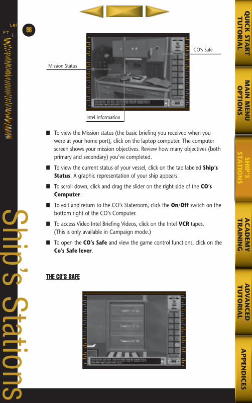
■ To view the Mission status (the basic briefing you received when youwere at your home port), click on the laptop computer. The computerscreen shows your mission objectives. Review how many objectives (bothprimary and secondary) you’ve completed.
■ To view the current status of your vessel, click on the tab labeled Ship’sStatus. A graphic representation of your ship appears.
■ To scroll down, click and drag the slider on the right side of the CO’sComputer.
■ To exit and return to the CO’s Stateroom, click the On/Off switch on thebottom right of the CO’s Computer.
■ To access Video Intel Briefing Videos, click on the Intel VCR tapes.(This is only available in Campaign mode.)
■ To open the CO’s Safe and view the game control functions, click on theCo’s Safe lever.
THE CO’S SAFE
FT
18096
Ship’s Stations
MA
IN M
ENU
OP
TIO
NS
AC
AD
EMY
TR
AIN
ING
AD
VA
NC
EDT
UT
OR
IAL
AP
PEN
DIC
ESQ
UIC
K STA
RT
TU
TO
RIA
LSH
IP’S
STAT
ION
S
Mission Status
CO’s Safe
Intel Information
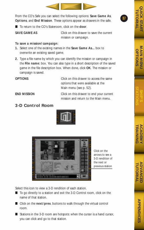
From the CO’s Safe you can select the following options: Save Game As,Options, and End Mission. These options appear as drawers in the safe.
■ To return to the CO’s Stateroom, click on the door.
SAVE GAME AS Click on this drawer to save the current mission or campaign.
To save a mission/campaign:1. Select one of the existing names in the Save Game As... box to
overwrite an existing saved game.
2. Type a file name by which you can identify the mission or campaign inthe File name: box. You can also type in a short description of the savedgame in the file description box. When done, click OK. The mission orcampaign is saved.
OPTIONS Click on this drawer to access the same options that were available at the Main menu (see p. 52).
END MISSION Click on this drawer to end your currentmission and return to the Main menu.
3-D Control Room
Select this icon to view a 3-D rendition of each station. ■ To go directly to a station and exit the 3-D Control room, click on the
name of that station.
■ Click on the next/prev. buttons to walk through the virtual controlroom.
■ Stations in the 3-D room are hotspots: when the cursor is a hand cursor,you can click and go to that station.
97
MA
IN M
ENU
OP
TIO
NS
AC
AD
EMY
TR
AIN
ING
AD
VA
NC
EDT
UT
OR
IAL
AP
PEN
DIC
ESQ
UIC
K STA
RT
TU
TO
RIA
LSH
IP’S
STAT
ION
S
Click on thearrows to see a 3-D rendition ofthe next or previous station
688(i)/AttackSubChptr3 5/6/98 10:48 AM Page 35
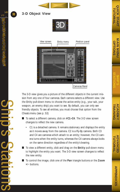
3-D Object View
The 3-D view gives you a picture of the different objects in the current mis-sion from any one of four cameras. Each camera selects a different view. Usethe Entity pull-down menu to choose the active entity (e.g., your sub, yourweapon, an enemy ship) you want to see. By default, you can only seefriendly objects. To see all entities, you must choose that option from theCheats menu (see p. 53)
■ To select a different camera, click on #C1–C4. The 3-D view screenchanges to reflect the new camera.
• C1 is a detached camera. It remains stationary and displays the entityas it moves away from the camera. C2 is a Fly-By camera. Both C3and C4 are cameras which attach to an entity; however, the C3 cam-era turns when the entity turns, whereas the C4 camera always lookson the same direction regardless of the entity’s bearing.
■ To view a different entity, click and drag on the Entity pull-down menuto highlight the entity you want. The 3-D view screen changes to reflectthe new entity.
■ To control the image, click one of the Pan triangle buttons or the Zoom+/- buttons.
FT
180
98
Ship’s Stations
MA
IN M
ENU
OP
TIO
NS
AC
AD
EMY
TR
AIN
ING
AD
VA
NC
EDT
UT
OR
IAL
AP
PEN
DIC
ESQ
UIC
K STA
RT
TU
TO
RIA
LSH
IP’S
STAT
ION
SCameras Panel
Entity menuView screen Position panel
688(i)/AttackSubChptr3 5/6/98 10:48 AM Page 36
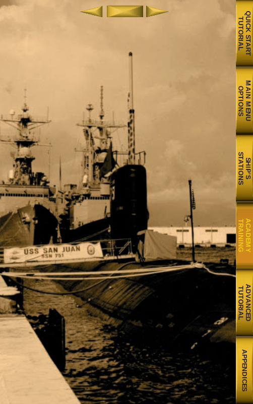
MA
IN M
ENU
OP
TIO
NS
AD
VA
NC
EDT
UT
OR
IAL
AP
PEN
DIC
ESQ
UIC
K STA
RT
TU
TO
RIA
LSH
IP’S
STAT
ION
SA
CA
DEM
YT
RA
ININ
G
688(i)/AttackSubChptr3 5/6/98 10:48 AM Page 37
FT
180
100
Academy Training
Chapter 4:
Academy TrainingTEN MISSION PHASES................................................102PREPARING FOR THE MISSION ..................................102
Evaluating the Mission Objectives ..............................................102Upgrading Your Ship ....................................................................102Choosing Your Weapon Loadout ................................................103
RECEIVING THE LATEST MISSION DATA ....................104MANEUVERING AND NAVIGATING ............................104
Buoyancy and Weight ..................................................................104Hydrodynamic Forces ..................................................................107Diving ..........................................................................................108Surfacing ......................................................................................108Maneuver Hazards ........................................................................109
MAINTAINING STEALTH ............................................111Sonar and the Ocean Environment ............................................111Use Thermal Layers to Your Advantage ......................................114Use Active Sensors ........................................................................114Avoid Cavitating ..........................................................................114Limit Your Speed ..........................................................................115Operate In Your Opponent’s Baffles ............................................115Avoid Depth Stress........................................................................116Raise Masts Only When Necessary ..............................................116Use Discretion When Attacking ..................................................117
DETECTING CONTACTS..............................................117Periscope ......................................................................................118Radar ............................................................................................119ESM ..............................................................................................121Sonar ............................................................................................124688(I) Sensor Comparison Table ..................................................132
CLASSIFYING CONTACTS ..........................................136Classification Using Narrowband Sonar ......................................136Classification Using the Periscope ..............................................138Classification Using ESM..............................................................140Classification Using the DEMON ................................................140
TARGETING CONTACTS ............................................141Targeting With Active Sensors......................................................141Targeting With Passive Sonar ......................................................142
688(I) WEAPON LAUNCHERS ....................................152688(I) WEAPON TYPES ..............................................154
MA
IN M
ENU
OP
TIO
NS
AD
VA
NC
EDT
UT
OR
IAL
AP
PEN
DIC
ESQ
UIC
K STA
RT
TU
TO
RIA
LSH
IP’S
STAT
ION
SA
CA
DEM
YT
RA
ININ
G
688(i)/AttackSubChptr4 5/6/98 11:12 AM Page ifc2
LAUNCHING WEAPONS ............................................157Launching Missiles Horizontally..................................................157Vertical Launch of Missiles ..........................................................157ADCAP Torpedo Launch ..............................................................157Launching Harpoons....................................................................162Launching Tomahawks ................................................................165Launching Mines..........................................................................168
EVASIVE MANEUVERS................................................171Torpedo Evasion ..........................................................................171
SPECIAL FORCES OPERATIONS ..................................173Submerged Lock out Procedure....................................................174Submerged Lock in Procedure......................................................174Surfaced Launch Procedure ..........................................................175Surfaced Recovery Procedure........................................................176Launching Special Operations Forces ..........................................176Recovering Special Operations Forces ..........................................177
SEARCH AND RESCUE OPERATIONS ..........................177Principles of the Operating Procedure ........................................177Surface Search and Rescue Procedure ..........................................177DSRV Operations ..........................................................................178
CASUALTY PROCEDURES ..........................................178Flooding Procedure ......................................................................179Emergency Deep ..........................................................................179
MISSION PROFILES ....................................................182Anti-Submarine Warfare ..............................................................182Anti-Surface Ship Warfare ............................................................182Strike Warfare................................................................................183Mine Warfare ................................................................................183Naval Special Warfare ..................................................................184Surveillance ..................................................................................184
Only a thorough understanding of the principles of submarine warfare and thecapabilities of your ship can prepare you to command the world’s most sophisti-
cated nuclear attack submarine.
Chapter 4 provides an in-depth review of the purpose and operation of everypiece of equipment you will use to carry out your missions. In addition, it includesdetailed principles and tactics of modern submarine warfare. Use this information
to take full advantage of the 688(I).
101
MA
IN M
ENU
OP
TIO
NS
AD
VA
NC
EDT
UT
OR
IAL
AP
PEN
DIC
ESQ
UIC
K STA
RT
TU
TO
RIA
LSH
IP’S
STAT
ION
SA
CA
DEM
YT
RA
ININ
G
688(i)/AttackSubChptr4 5/6/98 11:12 AM Page 1
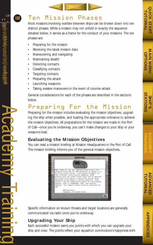
Ten Mission PhasesMost missions involving warfare between ships can be broken down into tendistinct phases. While a mission may not unfold in exactly the sequencedetailed below, it serves as a frame for the conduct of your missions. The tenphases are:
• Preparing for the mission• Receiving the latest mission data• Maneuvering and navigating• Maintaining stealth• Detecting contacts• Classifying contacts• Targeting contacts• Preparing the attack• Launching weapons• Taking evasive maneuvers in the event of counter-attack
General considerations for each of the phases are described in the sectionsbelow.
Preparing For the MissionPreparing for the mission includes evaluating the mission objectives, upgrad-ing the ship when possible, and loading the appropriate ordnance to achievethe mission objectives. All preparations for the mission are made in the Portof Call—once you’re underway, you can’t make changes to your ship or yourweapons load.
Evaluating the Mission ObjectivesYou can read a mission briefing at Mission Headquarters in the Port of Call.The mission briefing informs you of the general mission objectives.
Specific information on known threats and target locations are generallycommunicated via radio once you’re underway.
Upgrading Your ShipEach successful mission earns you points with which you can upgrade yourship and crew. The points reflect your squadron commodore’s happiness with
FT
180
102
Academy Training
MA
IN M
ENU
OP
TIO
NS
AD
VA
NC
EDT
UT
OR
IAL
AP
PEN
DIC
ESQ
UIC
K STA
RT
TU
TO
RIA
LSH
IP’S
STAT
ION
SA
CA
DEM
YT
RA
ININ
G
688(i)/AttackSubChptr4 5/6/98 11:12 AM Page 2
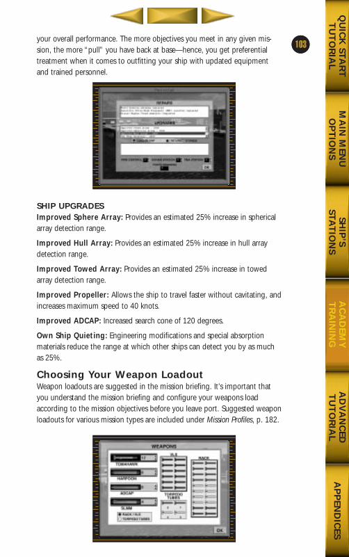
1your overall performance. The more objectives you meet in any given mis-sion, the more “pull” you have back at base—hence, you get preferentialtreatment when it comes to outfitting your ship with updated equipmentand trained personnel.
SHIP UPGRADESImproved Sphere Array: Provides an estimated 25% increase in sphericalarray detection range.
Improved Hull Array: Provides an estimated 25% increase in hull arraydetection range.
Improved Towed Array: Provides an estimated 25% increase in towedarray detection range.
Improved Propeller: Allows the ship to travel faster without cavitating, andincreases maximum speed to 40 knots.
Improved ADCAP: Increased search cone of 120 degrees.
Own Ship Quieting: Engineering modifications and special absorptionmaterials reduce the range at which other ships can detect you by as muchas 25%.
Choosing Your Weapon LoadoutWeapon loadouts are suggested in the mission briefing. It’s important thatyou understand the mission briefing and configure your weapons loadaccording to the mission objectives before you leave port. Suggested weaponloadouts for various mission types are included under Mission Profiles, p. 182.
103
MA
IN M
ENU
OP
TIO
NS
AD
VA
NC
EDT
UT
OR
IAL
AP
PEN
DIC
ESQ
UIC
K STA
RT
TU
TO
RIA
LSH
IP’S
STAT
ION
SA
CA
DEM
YT
RA
ININ
G
688(i)/AttackSubChptr4 5/6/98 11:12 AM Page 3
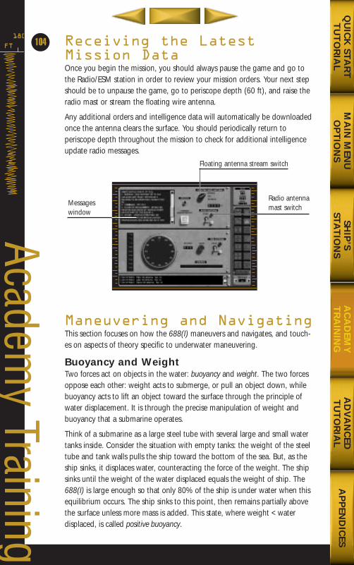
Receiving the LatestMission DataOnce you begin the mission, you should always pause the game and go tothe Radio/ESM station in order to review your mission orders. Your next stepshould be to unpause the game, go to periscope depth (60 ft), and raise theradio mast or stream the floating wire antenna.
Any additional orders and intelligence data will automatically be downloadedonce the antenna clears the surface. You should periodically return toperiscope depth throughout the mission to check for additional intelligenceupdate radio messages.
Maneuvering and NavigatingThis section focuses on how the 688(I) maneuvers and navigates, and touch-es on aspects of theory specific to underwater maneuvering.
Buoyancy and WeightTwo forces act on objects in the water: buoyancy and weight. The two forcesoppose each other: weight acts to submerge, or pull an object down, whilebuoyancy acts to lift an object toward the surface through the principle ofwater displacement. It is through the precise manipulation of weight andbuoyancy that a submarine operates.
Think of a submarine as a large steel tube with several large and small watertanks inside. Consider the situation with empty tanks: the weight of the steeltube and tank walls pulls the ship toward the bottom of the sea. But, as theship sinks, it displaces water, counteracting the force of the weight. The shipsinks until the weight of the water displaced equals the weight of ship. The688(I) is large enough so that only 80% of the ship is under water when thisequilibrium occurs. The ship sinks to this point, then remains partially abovethe surface unless more mass is added. This state, where weight < waterdisplaced, is called positive buoyancy.
FT
180
104
Academy Training
MA
IN M
ENU
OP
TIO
NS
AD
VA
NC
EDT
UT
OR
IAL
AP
PEN
DIC
ESQ
UIC
K STA
RT
TU
TO
RIA
LSH
IP’S
STAT
ION
SA
CA
DEM
YT
RA
ININ
G
Messages window
Floating antenna stream switch
Radio antennamast switch
688(i)/AttackSubChptr4 5/6/98 11:12 AM Page 4
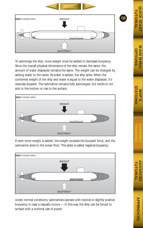
To submerge the ship, more weight must be added to decrease buoyancy.Since the overall physical dimensions of the ship remain the same, theamount of water displaced remains the same. The weight can be changed byadding water to the tanks. As water is added, the ship sinks. When the combined weight of the ship and water is equal to the water displaced, it’sneutrally buoyant. The submarine remains fully submerged, but tends to notsink to the bottom or rise to the surface.
If even more weight is added, the weight exceeds the buoyant force, and thesubmarine sinks to the ocean floor. This state is called negative buoyancy.
Under normal conditions, submarines operate with neutral or slightly positivebuoyancy in case a casualty occurs — in this way the ship can be forced tosurface with a minimal use of power.
105
MA
IN M
ENU
OP
TIO
NS
AD
VA
NC
EDT
UT
OR
IAL
AP
PEN
DIC
ESQ
UIC
K STA
RT
TU
TO
RIA
LSH
IP’S
STAT
ION
SA
CA
DEM
YT
RA
ININ
G
WEIGHT
BUOYANCY
FLOODED AREA
WEIGHT
BUOYANCY
FLOODED AREA
WEIGHT
BUOYANCY
FLOODED AREA
688(i)/AttackSubChptr4 5/6/98 11:12 AM Page 5
During this discussion, it has been assumed that the forces of weight andbuoyancy are acting evenly on the submarine, but it is easy to imagine theresults if this were not the case. If all the air tanks in the stern are full, butthose in the bow are not, the ship will look like it is standing on its head.Keeping the submarine trim and the weight evenly distributed are veryimportant to efficient navigation. In 688(I) Hunter/Killer, the crew automati-cally maintains a trim ship unless ordered otherwise.
PROPULSIONTwo sources of power, diesel-electric and nuclear, have proven effective forsubmarine propulsion.
CONVENTIONAL SUBMARINES
Conventional submarines use diesel engines and electric batteries for power.On the surface, the sub can run on diesel power—a very noisy power plant,but one that is cheap and easy to maintain. Once submerged, the ship canoperate silently on batteries for a number of hours, after which it mustrecharge its battery by running the diesel engines. This is accomplished byreturning to the surface or by a snorkel tube that can be raised above thesurface to draw in oxygen and expel exhaust.
Conventional submarines have the advantage of being virtually silent whenoperating on battery power. Unfortunately, the time they can spend sub-merged is very limited, and the hours they must spend on the surface makethem even more vulnerable to attack. Despite these disadvantages, conven-tional submarines are inexpensive to both buy and operate, making thempopular among the majority of the world’s navies.
NUCLEAR SUBMARINES
Nuclear submarines use one or more nuclear reactors to heat water, which inturn drives a turbine connected to the propeller shaft. Reactor types varyaccording to the coolant used to transfer energy from the reactor to the tur-bine. The most common design uses pressurized water to control the poweroutput of the reactor. These large systems allow the water coolant to circu-late by natural convection, thus avoiding noisy water pumps. Less commonare liquid metal-cooled reactors, which require pumps to drive their sec-ondary water systems. While experiments such as the Soviet Alfa class SSNhave proven that liquid metal-cooled systems are inherently louder, they ahave the advantage of being smaller and more powerful.
Nuclear submarines have many advantages over conventional subs. With noneed to recharge batteries, nuclear subs can spend months at sea withoutsurfacing. Their major drawback is strictly financial—nuclear submarines arevery expensive to build and operate. So expensive, that only the most afflu-ent countries can maintain nuclear fleets. They’re larger and noisier than con-ventional submarines, but these negative characteristics tend to be out-
FT
180
64
Academy Training
MA
IN M
ENU
OP
TIO
NS
AD
VA
NC
EDT
UT
OR
IAL
AP
PEN
DIC
ESQ
UIC
K STA
RT
TU
TO
RIA
LSH
IP’S
STAT
ION
SA
CA
DEM
YT
RA
ININ
G
106
688(i)/AttackSubChptr4 5/6/98 11:12 AM Page 6
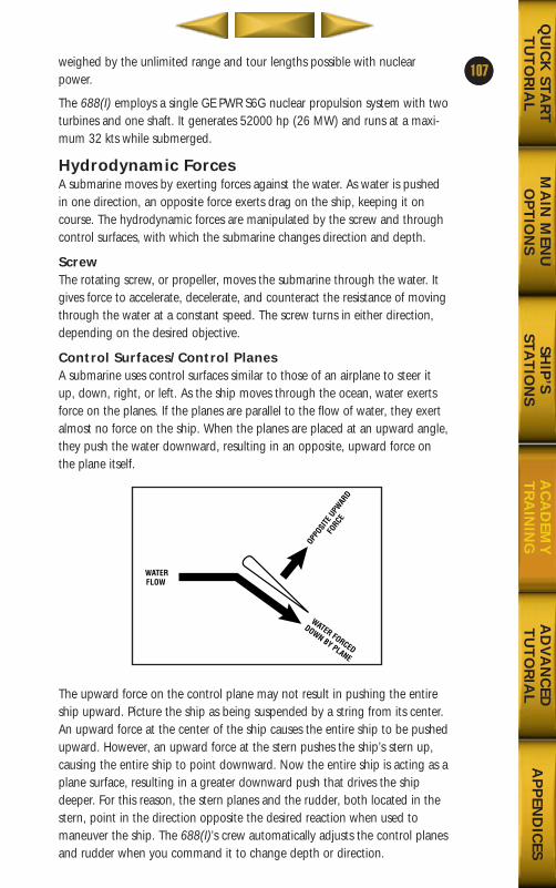
5weighed by the unlimited range and tour lengths possible with nuclearpower.
The 688(I) employs a single GE PWR S6G nuclear propulsion system with twoturbines and one shaft. It generates 52000 hp (26 MW) and runs at a maxi-mum 32 kts while submerged.
Hydrodynamic ForcesA submarine moves by exerting forces against the water. As water is pushedin one direction, an opposite force exerts drag on the ship, keeping it oncourse. The hydrodynamic forces are manipulated by the screw and throughcontrol surfaces, with which the submarine changes direction and depth.
ScrewThe rotating screw, or propeller, moves the submarine through the water. Itgives force to accelerate, decelerate, and counteract the resistance of movingthrough the water at a constant speed. The screw turns in either direction,depending on the desired objective.
Control Surfaces/Control PlanesA submarine uses control surfaces similar to those of an airplane to steer itup, down, right, or left. As the ship moves through the ocean, water exertsforce on the planes. If the planes are parallel to the flow of water, they exertalmost no force on the ship. When the planes are placed at an upward angle,they push the water downward, resulting in an opposite, upward force onthe plane itself.
The upward force on the control plane may not result in pushing the entireship upward. Picture the ship as being suspended by a string from its center.An upward force at the center of the ship causes the entire ship to be pushedupward. However, an upward force at the stern pushes the ship’s stern up,causing the entire ship to point downward. Now the entire ship is acting as aplane surface, resulting in a greater downward push that drives the shipdeeper. For this reason, the stern planes and the rudder, both located in thestern, point in the direction opposite the desired reaction when used tomaneuver the ship. The 688(I)’s crew automatically adjusts the control planesand rudder when you command it to change depth or direction.
107
MA
IN M
ENU
OP
TIO
NS
AD
VA
NC
EDT
UT
OR
IAL
AP
PEN
DIC
ESQ
UIC
K STA
RT
TU
TO
RIA
LSH
IP’S
STAT
ION
SA
CA
DEM
YT
RA
ININ
G
WATERFLOW
OPPOSI
TE U
PWAR
D
FORCE
WATER FORCED
DOWN BY PLANE
688(i)/AttackSubChptr4 5/6/98 11:12 AM Page 7
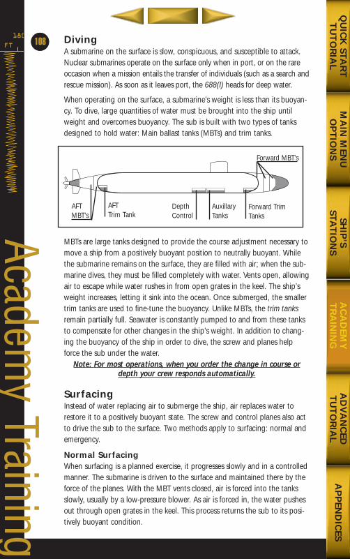
DivingA submarine on the surface is slow, conspicuous, and susceptible to attack.Nuclear submarines operate on the surface only when in port, or on the rareoccasion when a mission entails the transfer of individuals (such as a search andrescue mission). As soon as it leaves port, the 688(I) heads for deep water.
When operating on the surface, a submarine’s weight is less than its buoyan-cy. To dive, large quantities of water must be brought into the ship untilweight and overcomes buoyancy. The sub is built with two types of tanksdesigned to hold water: Main ballast tanks (MBTs) and trim tanks.
MBTs are large tanks designed to provide the course adjustment necessary tomove a ship from a positively buoyant position to neutrally buoyant. Whilethe submarine remains on the surface, they are filled with air; when the sub-marine dives, they must be filled completely with water. Vents open, allowingair to escape while water rushes in from open grates in the keel. The ship’sweight increases, letting it sink into the ocean. Once submerged, the smallertrim tanks are used to fine-tune the buoyancy. Unlike MBTs, the trim tanksremain partially full. Seawater is constantly pumped to and from these tanksto compensate for other changes in the ship’s weight. In addition to chang-ing the buoyancy of the ship in order to dive, the screw and planes helpforce the sub under the water.
Note: For most operations, when you order the change in course ordepth your crew responds automatically.
SurfacingInstead of water replacing air to submerge the ship, air replaces water torestore it to a positively buoyant state. The screw and control planes also actto drive the sub to the surface. Two methods apply to surfacing: normal andemergency.
Normal SurfacingWhen surfacing is a planned exercise, it progresses slowly and in a controlledmanner. The submarine is driven to the surface and maintained there by theforce of the planes. With the MBT vents closed, air is forced into the tanksslowly, usually by a low-pressure blower. As air is forced in, the water pushesout through open grates in the keel. This process returns the sub to its posi-tively buoyant condition.
FT
180
64
Academy Training
MA
IN M
ENU
OP
TIO
NS
AD
VA
NC
EDT
UT
OR
IAL
AP
PEN
DIC
ESQ
UIC
K STA
RT
TU
TO
RIA
LSH
IP’S
STAT
ION
SA
CA
DEM
YT
RA
ININ
G
108
AFTMBT’s
AFT Trim Tank
DepthControl
AuxillaryTanks
Forward TrimTanks
Forward MBT’s
688(i)/AttackSubChptr4 5/6/98 11:12 AM Page 8
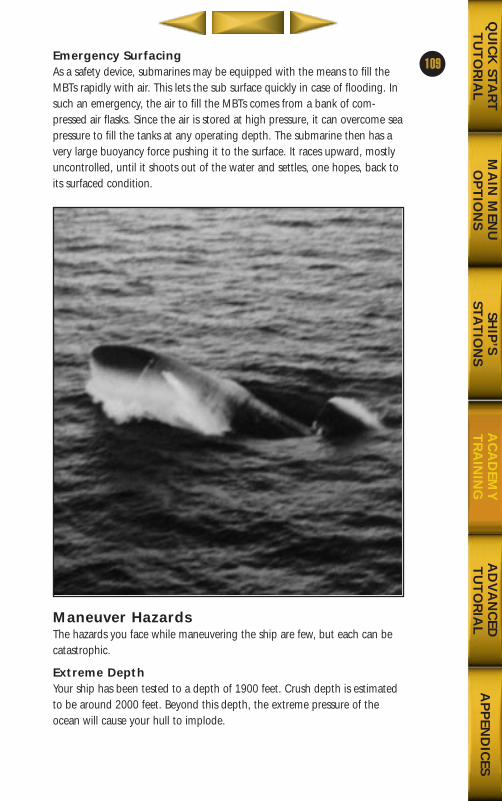
Emergency SurfacingAs a safety device, submarines may be equipped with the means to fill theMBTs rapidly with air. This lets the sub surface quickly in case of flooding. Insuch an emergency, the air to fill the MBTs comes from a bank of com-pressed air flasks. Since the air is stored at high pressure, it can overcome seapressure to fill the tanks at any operating depth. The submarine then has avery large buoyancy force pushing it to the surface. It races upward, mostlyuncontrolled, until it shoots out of the water and settles, one hopes, back toits surfaced condition.
Maneuver HazardsThe hazards you face while maneuvering the ship are few, but each can becatastrophic.
Extreme DepthYour ship has been tested to a depth of 1900 feet. Crush depth is estimatedto be around 2000 feet. Beyond this depth, the extreme pressure of theocean will cause your hull to implode.
109
MA
IN M
ENU
OP
TIO
NS
AD
VA
NC
EDT
UT
OR
IAL
AP
PEN
DIC
ESQ
UIC
K STA
RT
TU
TO
RIA
LSH
IP’S
STAT
ION
SA
CA
DEM
YT
RA
ININ
G
688(i)/AttackSubChptr4 5/6/98 11:13 AM Page 9
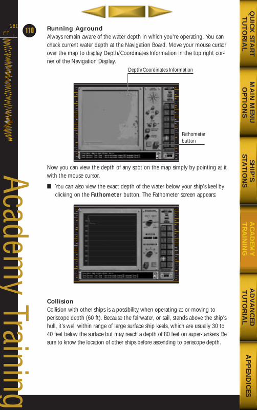
Running AgroundAlways remain aware of the water depth in which you’re operating. You cancheck current water depth at the Navigation Board. Move your mouse cursorover the map to display Depth/Coordinates Information in the top right cor-ner of the Navigation Display.
Now you can view the depth of any spot on the map simply by pointing at itwith the mouse cursor.
■ You can also view the exact depth of the water below your ship’s keel byclicking on the Fathometer button. The Fathometer screen appears:
CollisionCollision with other ships is a possibility when operating at or moving toperiscope depth (60 ft). Because the fairwater, or sail, stands above the ship’shull, it’s well within range of large surface ship keels, which are usually 30 to40 feet below the surface but may reach a depth of 80 feet on super-tankers. Besure to know the location of other ships before ascending to periscope depth.
FT
180
64
Academy Training
MA
IN M
ENU
OP
TIO
NS
AD
VA
NC
EDT
UT
OR
IAL
AP
PEN
DIC
ESQ
UIC
K STA
RT
TU
TO
RIA
LSH
IP’S
STAT
ION
SA
CA
DEM
YT
RA
ININ
G
110
Fathometerbutton
Depth/Coordinates Information
688(i)/AttackSubChptr4 5/6/98 11:13 AM Page 10
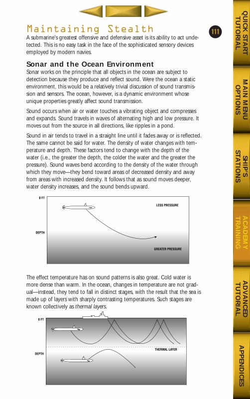
Maintaining StealthA submarine’s greatest offensive and defensive asset is its ability to act unde-tected. This is no easy task in the face of the sophisticated sensory devicesemployed by modern navies.
Sonar and the Ocean EnvironmentSonar works on the principle that all objects in the ocean are subject todetection because they produce and reflect sound. Were the ocean a staticenvironment, this would be a relatively trivial discussion of sound transmis-sion and sensors. The ocean, however, is a dynamic environment whoseunique properties greatly affect sound transmission.
Sound occurs when air or water touches a vibrating object and compressesand expands. Sound travels in waves of alternating high and low pressure. Itmoves out from the source in all directions, like ripples in a pond.
Sound in air tends to travel in a straight line until it fades away or is reflected.The same cannot be said for water. The density of water changes with tem-perature and depth. These factors tend to change with the depth of thewater (i.e., the greater the depth, the colder the water and the greater thepressure). Sound waves bend according to the density of the water throughwhich they move—they bend toward areas of decreased density and awayfrom areas with increased density. It follows that as sound moves deeper,water density increases, and the sound bends upward.
The effect temperature has on sound patterns is also great. Cold water ismore dense than warm. In the ocean, changes in temperature are not grad-ual—instead, they tend to fall in distinct stages, with the result that the sea ismade up of layers with sharply contrasting temperatures. Such stages areknown collectively as thermal layers.
111
MA
IN M
ENU
OP
TIO
NS
AD
VA
NC
EDT
UT
OR
IAL
AP
PEN
DIC
ESQ
UIC
K STA
RT
TU
TO
RIA
LSH
IP’S
STAT
ION
SA
CA
DEM
YT
RA
ININ
G
0 FT
DEPTH
LESS PRESSURE
GREATER PRESSURE
0 FT
DEPTHTHERMAL LAYER
688(i)/AttackSubChptr4 5/6/98 11:13 AM Page 11
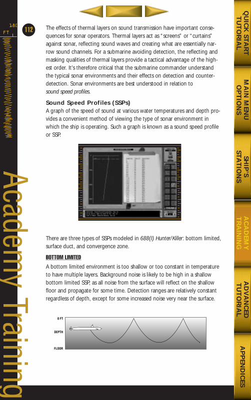
The effects of thermal layers on sound transmission have important conse-quences for sonar operators. Thermal layers act as “screens” or “curtains”against sonar, reflecting sound waves and creating what are essentially nar-row sound channels. For a submarine avoiding detection, the reflecting andmasking qualities of thermal layers provide a tactical advantage of the high-est order. It’s therefore critical that the submarine commander understandthe typical sonar environments and their effects on detection and counter-detection. Sonar environments are best understood in relation to sound speed profiles.
Sound Speed Profiles (SSPs)A graph of the speed of sound at various water temperatures and depth pro-vides a convenient method of viewing the type of sonar environment inwhich the ship is operating. Such a graph is known as a sound speed profileor SSP.
There are three types of SSPs modeled in 688(I) Hunter/Killer: bottom limited,surface duct, and convergence zone.
BOTTOM LIMITED
A bottom limited environment is too shallow or too constant in temperatureto have multiple layers. Background noise is likely to be high in a shallowbottom limited SSP, as all noise from the surface will reflect on the shallowfloor and propagate for some time. Detection ranges are relatively constantregardless of depth, except for some increased noise very near the surface.
FT
180
112
Academy Training
MA
IN M
ENU
OP
TIO
NS
AD
VA
NC
EDT
UT
OR
IAL
AP
PEN
DIC
ESQ
UIC
K STA
RT
TU
TO
RIA
LSH
IP’S
STAT
ION
SA
CA
DEM
YT
RA
ININ
G
0 FT
DEPTH
FLOOR
688(i)/AttackSubChptr4 5/6/98 11:13 AM Page 12
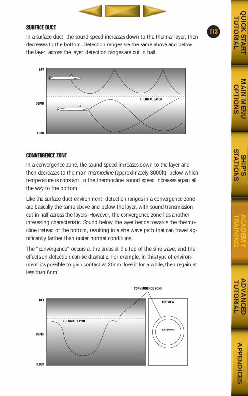
SURFACE DUCT
In a surface duct, the sound speed increases down to the thermal layer, thendecreases to the bottom. Detection ranges are the same above and belowthe layer; across the layer, detection ranges are cut in half.
CONVERGENCE ZONE
In a convergence zone, the sound speed increases down to the layer andthen decreases to the main thermocline (approximately 3000ft), below whichtemperature is constant. In the thermocline, sound speed increases again allthe way to the bottom.
Like the surface duct environment, detection ranges in a convergence zoneare basically the same above and below the layer, with sound transmissioncut in half across the layers. However, the convergence zone has anotherinteresting characteristic. Sound below the layer bends towards the thermo-cline instead of the bottom, resulting in a sine wave path that can travel sig-nificantly farther than under normal conditions.
The “convergence” occurs at the areas at the top of the sine wave, and theeffects on detection can be dramatic. For example, in this type of environ-ment it’s possible to gain contact at 20nm, lose it for a while, then regain atless than 6nm!
113
MA
IN M
ENU
OP
TIO
NS
AD
VA
NC
EDT
UT
OR
IAL
AP
PEN
DIC
ESQ
UIC
K STA
RT
TU
TO
RIA
LSH
IP’S
STAT
ION
SA
CA
DEM
YT
RA
ININ
G
0 FT
DEPTH
FLOOR
THERMAL LAYER
0 FT
DEPTH
FLOOR
THERMAL LAYER
CONVERGENCE ZONE
TOP VIEW
NOISE SOURCE
688(i)/AttackSubChptr4 5/6/98 11:13 AM Page 13
Use Thermal Layers to Your AdvantageAs shown above, thermal layers impede or enhance the transmission ofsound within the ocean environment. Thermal layers can be used to greatadvantage depending on the type of enemy ship your facing. When operat-ing against surface ships, it’s best to operate below the thermal layer in orderto cloak your movements as best as possible. On the other hand, if you’reengaging a submarine traveling below the thermal, you may choose to oper-ate above in the surface duct.
Keep in mind that thermal layers inhibit your sensors while simultaneouslycloaking your movements. The tradeoff is clear, and no simple formula canbe suggested that will fit every situation. Using thermals to your advantagedepends entirely on whether you’re attempting to remain undetected oroptimizing your sonar range.
Use of Active SensorsAll military ships carry passive receivers that warn when another ship is usingan active range-finding device. For instance, your own ship is equipped withpassive ESM sensors for the detection of surface radar emissions, and a sonar“intercept” device that detects another ship’s use of active sonar.
If you employ active radar or active sonar, be aware that you are communi-cating four things to other ships in your area, whether they are friendly, neu-tral, or hostile:
■ Your presence. If you had been operating covertly up to this point, youno longer are.
■ Your bearing. Any ships that picked up your active emission are imme-diately aware of your bearing to them. If they have weapons to spare,they may not hesitate to fire a snapshot at you.
■ Your proximity. Other ships may not know the exact range to yoursubmarine, but the relative strength of your active signal will give them ageneral idea of your proximity.
■ Who you are. While all active sonar and active radar systems are similar,each uses unique frequencies. Other ships can quickly determine that youare a US attack submarine by analyzing the frequencies of your sonar orradar.
Avoid CavitatingWhen a ship’s propeller moves so fast that the water around it can’t fill thecavity created by its motion, partial vacuums form around the blades. Thisphenomenon—know as cavitation—is particularly noisy. A high level of cavi-tation can advertise a submarine’s presence as surely as surfacing.
Cavitation is a dynamic interaction between the submarine’s speed and depth.Speed tends to increase cavitation, while depth tends to reduce it. The care-
FT
180
114
Academy Training
MA
IN M
ENU
OP
TIO
NS
AD
VA
NC
EDT
UT
OR
IAL
AP
PEN
DIC
ESQ
UIC
K STA
RT
TU
TO
RIA
LSH
IP’S
STAT
ION
SA
CA
DEM
YT
RA
ININ
G
688(i)/AttackSubChptr4 5/6/98 11:13 AM Page 14
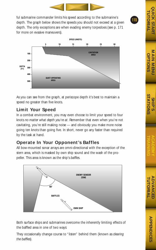
MA
IN M
ENU
OP
TIO
NS
AD
VA
NC
EDT
UT
OR
IAL
AP
PEN
DIC
ESQ
UIC
K STA
RT
TU
TO
RIA
LSH
IP’S
STAT
ION
SA
CA
DEM
YT
RA
ININ
G
115ful submarine commander limits his speed according to the submarine’sdepth. The graph below shows the speeds you should not exceed at a givendepth. The only exceptions are when evading enemy torpedoes (see p. 171for more on evasive maneuvers).
As you can see from the graph, at periscope depth it’s best to maintain aspeed no greater than five knots.
Limit Your SpeedIn a combat environment, you may even choose to limit your speed to fourknots no matter what depth you’re at. Remember that even when you’re notcavitating, you’re still making noise — and obviously you make more noisegoing ten knots than going five. In short, never go any faster than requiredby the task at hand.
Operate In Your Opponent’s BafflesAll bow-mounted sonar arrays are omni-directional with the exception of thestern area, which is masked by own ship sound and the wash of the pro-peller. This area is known as the ship’s baffles.
Both surface ships and submarines overcome the inherently limiting effects ofthe baffled area in one of two ways:
They occasionally change course to “listen” behind them (known as clearingthe baffles).
100
200
300
400
500
5 10 15 20 25 30
DEPTH(FT)
SPEED (KNOTS)
QUIET OPERATINGAREA
CAVITATIONAREA
OWN SHIP
BAFFLES
60¡
ENEMY SENSORZONE
688(i)/AttackSubChptr4 5/6/98 11:13 AM Page 15
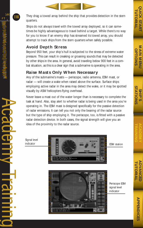
They drag a towed array behind the ship that provides detection in the sternquarters.
Ships do not always travel with the towed array deployed, so it can some-times be highly advantageous to travel behind a target. While there’s no wayfor you to know if an enemy ship has streamed its towed array, you shouldattempt to track ships from the stern quarters when safely possible.
Avoid Depth StressBeyond 950 feet, your ship’s hull is subjected to the stress of extreme waterpressure. This can result in creaking or groaning sounds that may be detectedby other ships in the area. In general, avoid traveling below 900 feet in a com-bat situation, as this is a clear sign that a submarine is operating in the area.
Raise Masts Only When NecessaryAny of the submarine’s masts — periscope, radio antenna, ESM mast, orradar — will create a wake when raised above the surface. Surface shipsemploying active radar in the area may detect the wake, or it may be spottedvisually by ASW helicopters flying overhead.
Never leave a mast out of the water longer than is necessary to complete thetask at hand. Also, stay alert to whether radar is being used in the area you’reoperating in. The ESM mast is designed specifically for the passive detectionof radar emissions. It can tell you not only the bearing of the radar sourcebut the type of ship employing it. The periscope, too, is fitted with a passiveradar detection device. In both cases, the signal strength will give you anidea of the proximity to the radar source.
FT
180
64
Academy Training
MA
IN M
ENU
OP
TIO
NS
AD
VA
NC
EDT
UT
OR
IAL
AP
PEN
DIC
ESQ
UIC
K STA
RT
TU
TO
RIA
LSH
IP’S
STAT
ION
SA
CA
DEM
YT
RA
ININ
G
116
Signal level indicator ESM station
Periscope ESMsignal levelindicator
688(i)/AttackSubChptr4 5/6/98 11:13 AM Page 16
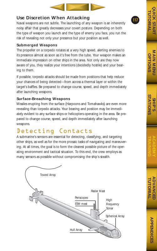
15Use Discretion When AttackingNaval weapons are not subtle. The launching of any weapon is an inherentlynoisy affair that greatly decreases your covert posture. Depending on boththe type of weapon you launch and the type of enemy you face, you run therisk of revealing not only your presence but your position as well.
Submerged WeaponsThe propeller on a torpedo rotates at a very high speed, alerting enemies toits presence almost as soon as it’s free from the tube. Your weapon makes animmediate impression on other ships in the area. Not only are they nowaware of you, they realize your intentions (decidedly hostile) and your bear-ing to them.
If possible, torpedo attacks should be made from positions that help reduceyour chances of being detected—from across a thermal layer or within thetarget’s baffles. Be prepared to change course, speed, and depth immediatelyafter launching weapons.
Surface-Breaching WeaponsMissiles erupting from the surface (Harpoons and Tomahawks) are even morerevealing than torpedo attacks. Your bearing and position may be immedi-ately evident to any surface ships or helicopters operating in the area. Be pre-pared to change course, speed, and depth immediately after launchingweapons.
Detecting ContactsA submarine’s sensors are essential for detecting, classifying, and targetingother ships, as well as for the more prosaic tasks of navigating and maneuver-ing. At all times, the goal is to form the clearest possible picture of the oper-ating environment and tactical situation. To this end, the crew employs asmany sensors as possible without compromising the ship’s stealth.
117
MA
IN M
ENU
OP
TIO
NS
AD
VA
NC
EDT
UT
OR
IAL
AP
PEN
DIC
ESQ
UIC
K STA
RT
TU
TO
RIA
LSH
IP’S
STAT
ION
SA
CA
DEM
YT
RA
ININ
G
Towed Array
Spherical Array
Hull Array
ESM mast
Periscopes
Radar Mast
HighFrequencySonar
688(i)/AttackSubChptr4 5/6/98 11:13 AM Page 17
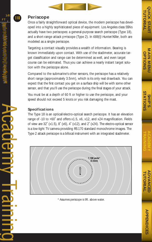
PeriscopeOnce a fairly straightforward optical device, the modern periscope has devel-oped into a highly sophisticated piece of equipment. Los Angeles class SSNsactually have two periscopes: a general-purpose search periscope (Type 18),and a short-range attack periscope (Type 2). In 688(I) Hunter/Killer, both aremodeled as a single periscope.
Targeting a contact visually provides a wealth of information. Bearing isknown immediately upon contact. With use of the stadimeter, accurate tar-get classification and range can be determined as well, and even targetcourse can be estimated. Thus you can achieve a nearly instant target solu-tion with the periscope alone.
Compared to the submarine’s other sensors, the periscope has a relativelyshort range (approximately 3.5nm), which is its only real drawback. You canexpect that the first contact you get on a surface ship will be with some othersensor, and that you’ll use the periscope during the final stages of your attack.
You must be at a depth of 60 ft or higher to use the periscope, and yourspeed should not exceed 5 knots or you risk damaging the mast.
SpecificationsThe Type 18 is an optical/electro-optical search periscope. It has an elevationrange of -10 to +60˚ and offers x1.5, x6, x12, and x24 magnification. Fieldsof view are 32˚ (x1.5), 8˚ (x6), 4˚ (x12), and 2˚ (x24). The electro-optical sensoris a low-light TV camera providing RS 170 standard monochrome images. TheType 2 attack periscope is a bifocal instrument with an integrated stadimeter.
* Assumes periscope is 9ft. above water.
FT
180
118
Academy Training
MA
IN M
ENU
OP
TIO
NS
AD
VA
NC
EDT
UT
OR
IAL
AP
PEN
DIC
ESQ
UIC
K STA
RT
TU
TO
RIA
LSH
IP’S
STAT
ION
SA
CA
DEM
YT
RA
ININ
G
7,100 yards*(3.5nm)
688(i)/AttackSubChptr4 5/6/98 11:13 AM Page 18
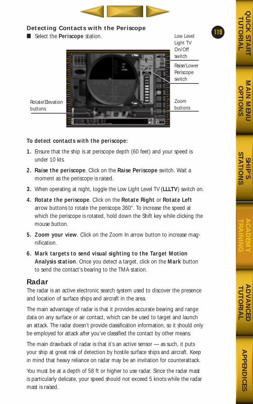
Detecting Contacts with the Periscope■ Select the Periscope station.
To detect contacts with the periscope:
1. Ensure that the ship is at periscope depth (60 feet) and your speed isunder 10 kts.
2. Raise the periscope. Click on the Raise Periscope switch. Wait amoment as the periscope is raised.
3. When operating at night, toggle the Low Light Level TV (LLLTV) switch on.
4. Rotate the periscope. Click on the Rotate Right or Rotate Leftarrow buttons to rotate the periscope 360°. To increase the speed atwhich the periscope is rotated, hold down the Shift key while clicking themouse button.
5. Zoom your view. Click on the Zoom In arrow button to increase mag-nification.
6. Mark targets to send visual sighting to the Target MotionAnalysis station. Once you detect a target, click on the Mark buttonto send the contact’s bearing to the TMA station.
RadarThe radar is an active electronic search system used to discover the presenceand location of surface ships and aircraft in the area.
The main advantage of radar is that it provides accurate bearing and rangedata on any surface or air contact, which can be used to target and launchan attack. The radar doesn’t provide classification information, so it should onlybe employed for attack after you’ve classified the contact by other means.
The main drawback of radar is that it’s an active sensor — as such, it putsyour ship at great risk of detection by hostile surface ships and aircraft. Keepin mind that heavy reliance on radar may be an invitation for counterattack.
You must be at a depth of 58 ft or higher to use radar. Since the radar mastis particularly delicate, your speed should not exceed 5 knots while the radarmast is raised.
119
MA
IN M
ENU
OP
TIO
NS
AD
VA
NC
EDT
UT
OR
IAL
AP
PEN
DIC
ESQ
UIC
K STA
RT
TU
TO
RIA
LSH
IP’S
STAT
ION
SA
CA
DEM
YT
RA
ININ
G
Rotate/Elevationbuttons
Low LevelLight TVOn/Offswitch
Raise/LowerPeriscopeswitch
Zoom buttons
688(i)/AttackSubChptr4 5/6/98 11:13 AM Page 19
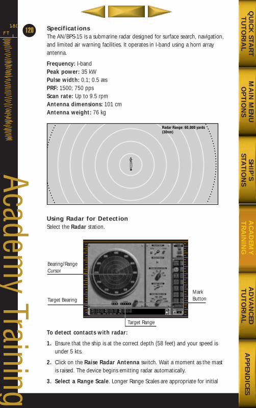
SpecificationsThe AN/BPS-15 is a submarine radar designed for surface search, navigation,and limited air warning facilities. It operates in I-band using a horn arrayantenna.
Frequency: I-bandPeak power: 35 kWPulse width: 0.1; 0.5 æsPRF: 1500; 750 ppsScan rate: Up to 9.5 rpmAntenna dimensions: 101 cmAntenna weight: 76 kg
Using Radar for DetectionSelect the Radar station.
To detect contacts with radar:
1. Ensure that the ship is at the correct depth (58 feet) and your speed isunder 5 kts.
2. Click on the Raise Radar Antenna switch. Wait a moment as the mastis raised. The device begins emitting radar automatically.
3. Select a Range Scale. Longer Range Scales are appropriate for initial
FT
180
120
Academy Training
MA
IN M
ENU
OP
TIO
NS
AD
VA
NC
EDT
UT
OR
IAL
AP
PEN
DIC
ESQ
UIC
K STA
RT
TU
TO
RIA
LSH
IP’S
STAT
ION
SA
CA
DEM
YT
RA
ININ
G
Radar Range: 60,000 yards(30nm)
Bearing/RangeCursor
Target BearingMarkButton
Target Range
688(i)/AttackSubChptr4 5/6/98 11:13 AM Page 20
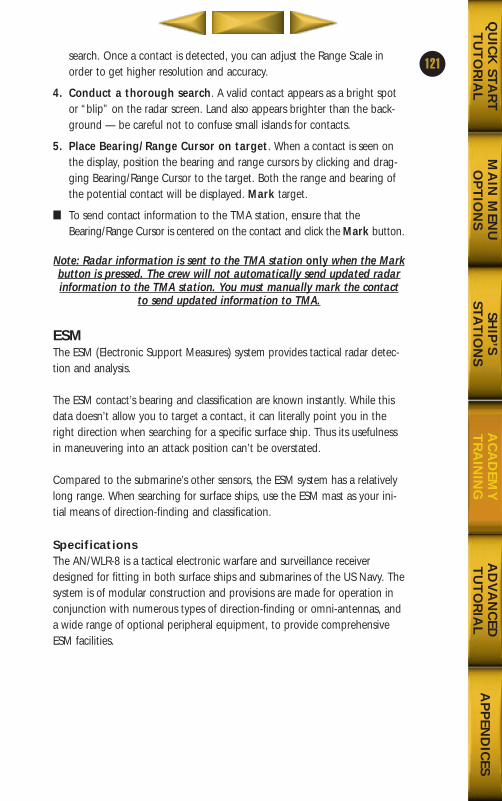
search. Once a contact is detected, you can adjust the Range Scale inorder to get higher resolution and accuracy.
4. Conduct a thorough search. A valid contact appears as a bright spotor “blip” on the radar screen. Land also appears brighter than the back-ground — be careful not to confuse small islands for contacts.
5. Place Bearing/Range Cursor on target. When a contact is seen onthe display, position the bearing and range cursors by clicking and drag-ging Bearing/Range Cursor to the target. Both the range and bearing ofthe potential contact will be displayed. Mark target.
■ To send contact information to the TMA station, ensure that theBearing/Range Cursor is centered on the contact and click the Mark button.
Note: Radar information is sent to the TMA station only when the Markbutton is pressed. The crew will not automatically send updated radarinformation to the TMA station. You must manually mark the contact
to send updated information to TMA.
ESMThe ESM (Electronic Support Measures) system provides tactical radar detec-tion and analysis.
The ESM contact’s bearing and classification are known instantly. While thisdata doesn’t allow you to target a contact, it can literally point you in theright direction when searching for a specific surface ship. Thus its usefulnessin maneuvering into an attack position can’t be overstated.
Compared to the submarine’s other sensors, the ESM system has a relativelylong range. When searching for surface ships, use the ESM mast as your ini-tial means of direction-finding and classification.
SpecificationsThe AN/WLR-8 is a tactical electronic warfare and surveillance receiverdesigned for fitting in both surface ships and submarines of the US Navy. Thesystem is of modular construction and provisions are made for operation inconjunction with numerous types of direction-finding or omni-antennas, anda wide range of optional peripheral equipment, to provide comprehensiveESM facilities.
121
MA
IN M
ENU
OP
TIO
NS
AD
VA
NC
EDT
UT
OR
IAL
AP
PEN
DIC
ESQ
UIC
K STA
RT
TU
TO
RIA
LSH
IP’S
STAT
ION
SA
CA
DEM
YT
RA
ININ
G
688(i)/AttackSubChptr4 5/6/98 11:13 AM Page 21
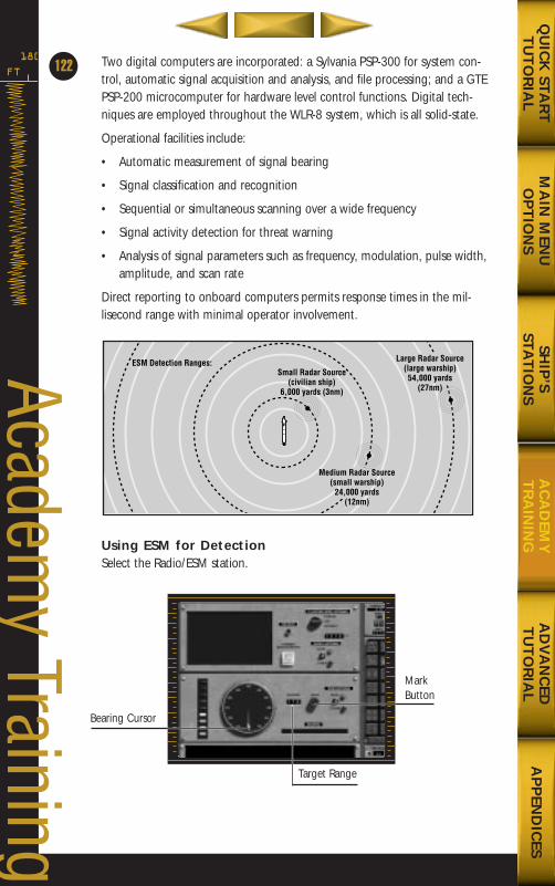
Two digital computers are incorporated: a Sylvania PSP-300 for system con-trol, automatic signal acquisition and analysis, and file processing; and a GTEPSP-200 microcomputer for hardware level control functions. Digital tech-niques are employed throughout the WLR-8 system, which is all solid-state.
Operational facilities include:
• Automatic measurement of signal bearing
• Signal classification and recognition
• Sequential or simultaneous scanning over a wide frequency
• Signal activity detection for threat warning
• Analysis of signal parameters such as frequency, modulation, pulse width,amplitude, and scan rate
Direct reporting to onboard computers permits response times in the mil-lisecond range with minimal operator involvement.
Using ESM for DetectionSelect the Radio/ESM station.
FT
180
122
Academy Training
MA
IN M
ENU
OP
TIO
NS
AD
VA
NC
EDT
UT
OR
IAL
AP
PEN
DIC
ESQ
UIC
K STA
RT
TU
TO
RIA
LSH
IP’S
STAT
ION
SA
CA
DEM
YT
RA
ININ
G
Bearing Cursor
MarkButton
Target Range
Large Radar Source(large warship)54,000 yards
(27nm)
Medium Radar Source(small warship)
24,000 yards(12nm)
Small Radar Source(civilian ship)
6,000 yards (3nm)
ESM Detection Ranges:
688(i)/AttackSubChptr4 5/6/98 11:13 AM Page 22
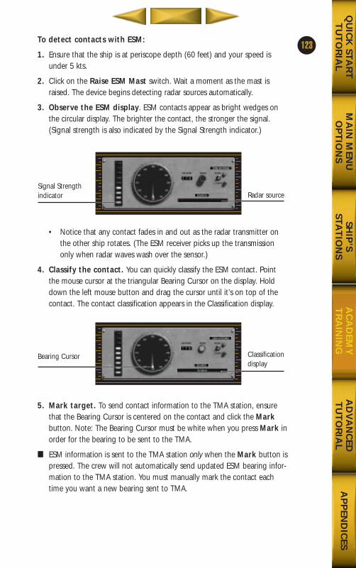
To detect contacts with ESM:
1. Ensure that the ship is at periscope depth (60 feet) and your speed isunder 5 kts.
2. Click on the Raise ESM Mast switch. Wait a moment as the mast israised. The device begins detecting radar sources automatically.
3. Observe the ESM display. ESM contacts appear as bright wedges onthe circular display. The brighter the contact, the stronger the signal.(Signal strength is also indicated by the Signal Strength indicator.)
• Notice that any contact fades in and out as the radar transmitter onthe other ship rotates. (The ESM receiver picks up the transmissiononly when radar waves wash over the sensor.)
4. Classify the contact. You can quickly classify the ESM contact. Pointthe mouse cursor at the triangular Bearing Cursor on the display. Holddown the left mouse button and drag the cursor until it’s on top of thecontact. The contact classification appears in the Classification display.
5. Mark target. To send contact information to the TMA station, ensurethat the Bearing Cursor is centered on the contact and click the Markbutton. Note: The Bearing Cursor must be white when you press Mark inorder for the bearing to be sent to the TMA.
■ ESM information is sent to the TMA station only when the Mark button ispressed. The crew will not automatically send updated ESM bearing infor-mation to the TMA station. You must manually mark the contact eachtime you want a new bearing sent to TMA.
123
MA
IN M
ENU
OP
TIO
NS
AD
VA
NC
EDT
UT
OR
IAL
AP
PEN
DIC
ESQ
UIC
K STA
RT
TU
TO
RIA
LSH
IP’S
STAT
ION
SA
CA
DEM
YT
RA
ININ
G
Signal Strengthindicator Radar source
Bearing Cursor Classificationdisplay
688(i)/AttackSubChptr4 5/6/98 11:13 AM Page 23
SonarSonar (Sound Navigation Ranging) is the submarine’s only means of detect-ing other submerged submarines, and below periscope depth it’s the onlymeans of detecting surface ships, too. For a hunter/killer, whose primary roleis anti-submarine and anti-surface ship warfare, sonar is the most importantsensor on board. Because sonar is inherently complex, its use requires a moreextensive explanation than the surface sensors.
Sound ProcessorsSubmarines use three devices to process sound signals underwater:hydrophones, projectors, and transducers. Hydrophones listen to sound, whileprojectors transmit sound. A transducer both listens and transmits.
Signals are detected over two different frequency ranges: broadband and narrowband. All contacts emit both broadband and narrowband signals.
Broadband contacts are those that put out significant acoustic energy over awide range of frequencies. The sonar receiver can look at a wide range of fre-quencies and see all of the contacts that emit energy somewhere within thatfrequency range. Broadband is used to detect a contact, but it can also givea limited amount of information on contact range (via signal strength).
Narrowband contacts are those that emit acoustic energy at discrete frequen-cies, usually attributable to a specific piece of machinery (motor, engine,pump, etc.). By eliminating the noise that is received at all other frequenciesand looking only for a specific frequency, a narrowband sonar receiver maybe able to detect the discrete frequency at longer ranges than the same con-tact could be detected by a broadband receiver.
Narrowband signals give additional information about the contact. The spe-cific frequencies emitted by a contact are akin to its fingerprint, readily anduniquely identifiable. These are commonly referred to as a sonar signature.See Classifying Contacts on p. 136 for more information.
Sonar ArraysAn array is an interconnected group of hydrophones or transducers thatfocus either the transmission or reception of sound. The 688(I) is equippedwith three arrays: a spherical array, hull array, and towed array. Together thearrays provide omni-directional sonar detection capabilities; however, noarray in itself provides full 360° detection. This is because the ship itself masksa certain amount of the environment from the sensor.
FT
180
64
Academy Training
MA
IN M
ENU
OP
TIO
NS
AD
VA
NC
EDT
UT
OR
IAL
AP
PEN
DIC
ESQ
UIC
K STA
RT
TU
TO
RIA
LSH
IP’S
STAT
ION
SA
CA
DEM
YT
RA
ININ
G
124
688(i)/AttackSubChptr4 5/6/98 11:13 AM Page 24

23SPHERICAL ARRAY
The spherical array in the bow is used at up to 25 knots and can track broad-band as well as narrowband contacts. Passive detection ranges from 750 Hzto 2.0 kHz. In active mode, the array transmits and detects at a higher fre-quency range of 2.0 kHz to 10 kHz.
The spherical array processes broadband signals better than other arrays.Bearing accuracy is particularly good. At higher speeds, there is some degra-dation of performance because of flow noise caused by the water movingacross the surface of the array. It is not as sensitive to low frequencies, so it’snot the array of choice for narrowband contacts emitting only low frequencies.
HULL ARRAY
The hull array, also at the bow of the ship, is a linear array that provides lowspeed capability to detect low frequency narrowband contacts (50 Hz -to-1.0 kHz). As such, its primary use is for classifying targets.
125
MA
IN M
ENU
OP
TIO
NS
AD
VA
NC
EDT
UT
OR
IAL
AP
PEN
DIC
ESQ
UIC
K STA
RT
TU
TO
RIA
LSH
IP’S
STAT
ION
SA
CA
DEM
YT
RA
ININ
G
688(i)/AttackSubChptr4 5/6/98 11:14 AM Page 25
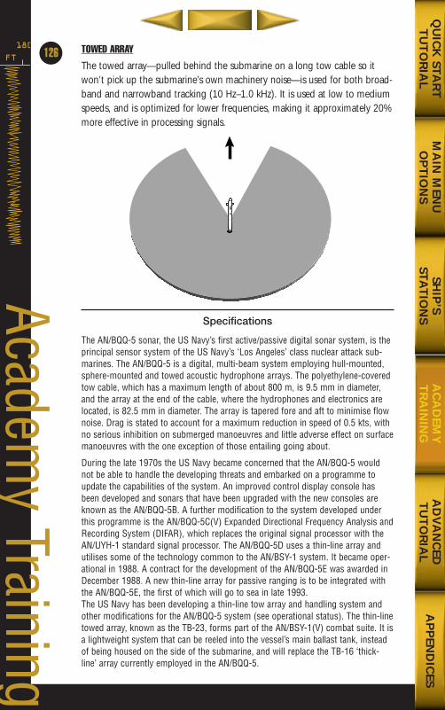
TOWED ARRAY
The towed array—pulled behind the submarine on a long tow cable so itwon’t pick up the submarine’s own machinery noise—is used for both broad-band and narrowband tracking (10 Hz–1.0 kHz). It is used at low to mediumspeeds, and is optimized for lower frequencies, making it approximately 20%more effective in processing signals.
Specifications
The AN/BQQ-5 sonar, the US Navy’s first active/passive digital sonar system, is theprincipal sensor system of the US Navy’s ‘Los Angeles’ class nuclear attack sub-marines. The AN/BQQ-5 is a digital, multi-beam system employing hull-mounted,sphere-mounted and towed acoustic hydrophone arrays. The polyethylene-coveredtow cable, which has a maximum length of about 800 m, is 9.5 mm in diameter,and the array at the end of the cable, where the hydrophones and electronics arelocated, is 82.5 mm in diameter. The array is tapered fore and aft to minimise flownoise. Drag is stated to account for a maximum reduction in speed of 0.5 kts, withno serious inhibition on submerged manoeuvres and little adverse effect on surfacemanoeuvres with the one exception of those entailing going about.
During the late 1970s the US Navy became concerned that the AN/BQQ-5 wouldnot be able to handle the developing threats and embarked on a programme toupdate the capabilities of the system. An improved control display console hasbeen developed and sonars that have been upgraded with the new consoles areknown as the AN/BQQ-5B. A further modification to the system developed underthis programme is the AN/BQQ-5C(V) Expanded Directional Frequency Analysis andRecording System (DIFAR), which replaces the original signal processor with theAN/UYH-1 standard signal processor. The AN/BQQ-5D uses a thin-line array andutilises some of the technology common to the AN/BSY-1 system. It became oper-ational in 1988. A contract for the development of the AN/BQQ-5E was awarded inDecember 1988. A new thin-line array for passive ranging is to be integrated withthe AN/BQQ-5E, the first of which will go to sea in late 1993.The US Navy has been developing a thin-line tow array and handling system andother modifications for the AN/BQQ-5 system (see operational status). The thin-linetowed array, known as the TB-23, forms part of the AN/BSY-1(V) combat suite. It isa lightweight system that can be reeled into the vessel’s main ballast tank, insteadof being housed on the side of the submarine, and will replace the TB-16 ‘thick-line’ array currently employed in the AN/BQQ-5.
FT
180
126
Academy Training
MA
IN M
ENU
OP
TIO
NS
AD
VA
NC
EDT
UT
OR
IAL
AP
PEN
DIC
ESQ
UIC
K STA
RT
TU
TO
RIA
LSH
IP’S
STAT
ION
SA
CA
DEM
YT
RA
ININ
G
688(i)/AttackSubChptr4 5/6/98 11:14 AM Page 26
The AN/BQQ-5 provides improved detection, tracking and classification of low fre-quency data. The latest development also provides processing capability for thenew TB-29 towed array and interfacing to the new fire-control system CCS Mk 2.The combining of the AN/BQQ-5E, TB-29, and CCS Mk 2 will result in a systemreferred to as QE2 that was scheduled for Technical Evaluation in 1993.The AN/WLR-9A acoustic intercept receiver, produced by Norden, has been suc-cessfully evaluated and forms an integral subsystem of the AN/BQQ-5 andAN/BQQ-6 on new attack and Trident missile submarines. The subsystem featuresa CRT display, a digital readout and a remote unit for the submarine commander. A‘sensitivity improvement’ kit for the AN/WLR-9A has been developed by Nordenand deliveries to the US Navy are in progress.
Passive SonarPassive sonar uses arrays of hydrophones to pick up sound waves. Thesearrays are located on various surfaces of the ship.
The hydrophone arrays transmit sound to the sonar station. Here you mustsift through the noise for familiar patterns created by natural and man-madesources. The detection process involves picking up signals on the broadbandor narrowband display using one or more arrays, and then designating con-tacts for tracking. Once a contact has been designated, the crew automati-cally tracks the contact (as long as it remains in sensor range) and periodical-ly sends updated bearing information to the Target Motion Analysis station(see Ship’s Stations on p. 62).
Passive sonar provides only bearing information on any contact. To classify ortarget a contact using passive sonar, further analysis is required at differentstations. Classification takes place in Narrowband mode (see Ship’s Stationson p. 62), while determining the target’s range, speed, and course is done at the Target Motion Analysis station. (See Targeting with Passive Sonar on p. 142.)
TRACKING BROADBAND CONTACTS
Select the Sonar station, and then click on the Broadband button.
127
MA
IN M
ENU
OP
TIO
NS
AD
VA
NC
EDT
UT
OR
IAL
AP
PEN
DIC
ESQ
UIC
K STA
RT
TU
TO
RIA
LSH
IP’S
STAT
ION
SA
CA
DEM
YT
RA
ININ
G
Broadband button
688(i)/AttackSubChptr4 5/6/98 11:14 AM Page 27
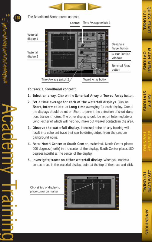
The Broadband Sonar screen appears.
To track a broadband contact:
1. Select an array. Click on the Spherical Array or Towed Array button.
2. Set a time average for each of the waterfall displays. Click onShort, Intermediate, or Long time averaging for each display. One ofthe displays should be set on Short to permit the detection of short dura-tion, transient noises. The other display should be set on Intermediate orLong, either of which will help you make out weaker contacts in the area.
3. Observe the waterfall display. Increased noise on any bearing willresult in a coherent trace that can be distinguished from the randombackground noise.
4. Select North Center or South Center, as desired. North Center places000 degrees (north) in the center of the display; South Center places 180degrees (south) at the center of the display.
5. Investigate traces on either waterfall display. When you notice acontact trace in the waterfall display, point at the top of the trace and click.
FT
180
128
Academy Training
MA
IN M
ENU
OP
TIO
NS
AD
VA
NC
EDT
UT
OR
IAL
AP
PEN
DIC
ESQ
UIC
K STA
RT
TU
TO
RIA
LSH
IP’S
STAT
ION
SA
CA
DEM
YT
RA
ININ
G
Waterfall display 1
Waterfall display 2
DesignateTarget button
Cursor PositionWindow
Spherical Arraybutton
Contact
Towed Array buttonTime Average switch 2
Time Average switch 1
Click at top of display toplace cursor on marker
688(i)/AttackSubChptr4 5/6/98 11:14 AM Page 28
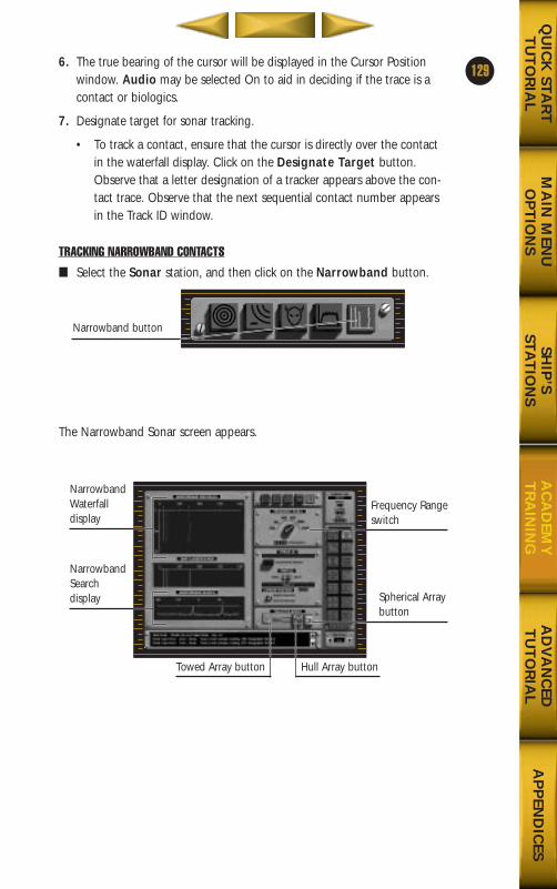
6. The true bearing of the cursor will be displayed in the Cursor Positionwindow. Audio may be selected On to aid in deciding if the trace is acontact or biologics.
7. Designate target for sonar tracking.
• To track a contact, ensure that the cursor is directly over the contactin the waterfall display. Click on the Designate Target button.Observe that a letter designation of a tracker appears above the con-tact trace. Observe that the next sequential contact number appearsin the Track ID window.
TRACKING NARROWBAND CONTACTS
■ Select the Sonar station, and then click on the Narrowband button.
The Narrowband Sonar screen appears.
129
MA
IN M
ENU
OP
TIO
NS
AD
VA
NC
EDT
UT
OR
IAL
AP
PEN
DIC
ESQ
UIC
K STA
RT
TU
TO
RIA
LSH
IP’S
STAT
ION
SA
CA
DEM
YT
RA
ININ
G
Narrowband button
NarrowbandWaterfalldisplay
NarrowbandSearch display Spherical Array
button
Hull Array buttonTowed Array button
Frequency Rangeswitch
688(i)/AttackSubChptr4 5/6/98 11:14 AM Page 29
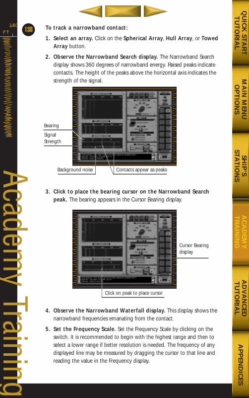
To track a narrowband contact:
1. Select an array. Click on the Spherical Array, Hull Array, or TowedArray button.
2. Observe the Narrowband Search display. The Narrowband Searchdisplay shows 360 degrees of narrowband energy. Raised peaks indicatecontacts. The height of the peaks above the horizontal axis indicates thestrength of the signal.
3. Click to place the bearing cursor on the Narrowband Searchpeak. The bearing appears in the Cursor Bearing display.
4. Observe the Narrowband Waterfall display. This display shows thenarrowband frequencies emanating from the contact.
5. Set the Frequency Scale. Set the Frequency Scale by clicking on theswitch. It is recommended to begin with the highest range and then toselect a lower range if better resolution is needed. The frequency of anydisplayed line may be measured by dragging the cursor to that line andreading the value in the Frequency display.
FT
180
130
Academy Training
Bearing
SignalStrength
Contacts appear as peaksBackground noise
Cursor Bearingdisplay
Click on peak to place cursor
MA
IN M
ENU
OP
TIO
NS
AD
VA
NC
EDT
UT
OR
IAL
AP
PEN
DIC
ESQ
UIC
K STA
RT
TU
TO
RIA
LSH
IP’S
STAT
ION
SA
CA
DEM
YT
RA
ININ
G
688(i)/AttackSubChptr4 5/6/98 11:14 AM Page 30
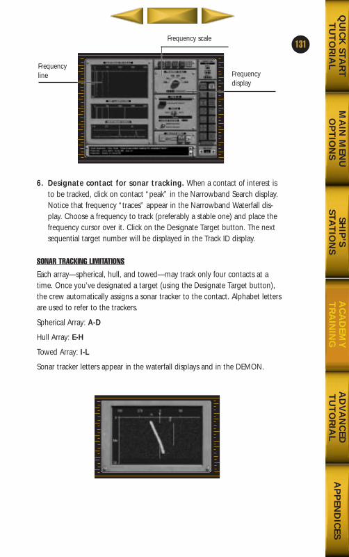
6. Designate contact for sonar tracking. When a contact of interest isto be tracked, click on contact “peak” in the Narrowband Search display.Notice that frequency “traces” appear in the Narrowband Waterfall dis-play. Choose a frequency to track (preferably a stable one) and place thefrequency cursor over it. Click on the Designate Target button. The nextsequential target number will be displayed in the Track ID display.
SONAR TRACKING LIMITATIONS
Each array—spherical, hull, and towed—may track only four contacts at atime. Once you’ve designated a target (using the Designate Target button),the crew automatically assigns a sonar tracker to the contact. Alphabet lettersare used to refer to the trackers.
Spherical Array: A-D
Hull Array: E-H
Towed Array: I-L
Sonar tracker letters appear in the waterfall displays and in the DEMON.
131
MA
IN M
ENU
OP
TIO
NS
AD
VA
NC
EDT
UT
OR
IAL
AP
PEN
DIC
ESQ
UIC
K STA
RT
TU
TO
RIA
LSH
IP’S
STAT
ION
SA
CA
DEM
YT
RA
ININ
G
Frequencyline Frequency
display
Frequency scale
688(i)/AttackSubChptr4 5/6/98 11:14 AM Page 31
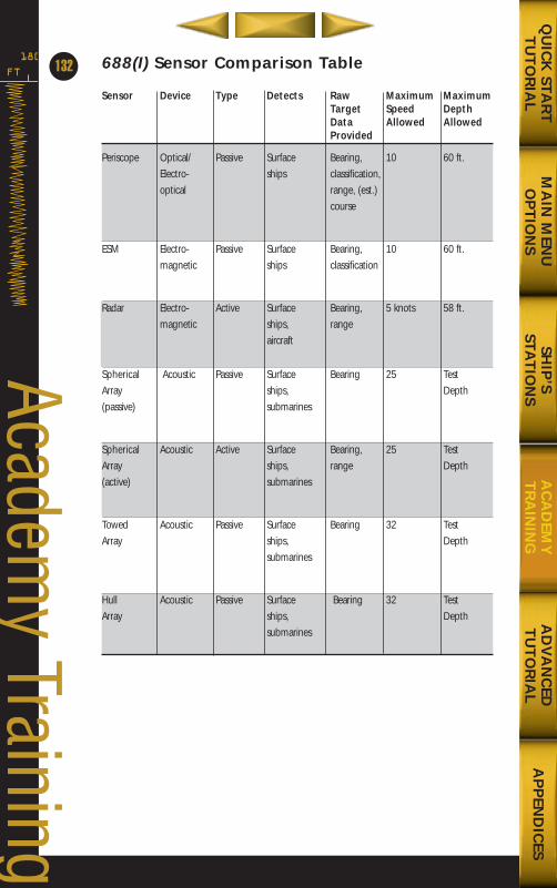
FT
180
132
Academy Training
688(I) Sensor Comparison Table
Sensor Device Type Detects Raw Maximum MaximumTarget Speed DepthData Allowed AllowedProvided
Periscope Optical/ Passive Surface Bearing, 10 60 ft.Electro- ships classification,optical range, (est.)
course
ESM Electro- Passive Surface Bearing, 10 60 ft.magnetic ships classification
Radar Electro- Active Surface Bearing, 5 knots 58 ft.magnetic ships, range
aircraft
Spherical Acoustic Passive Surface Bearing 25 Test Array ships, Depth(passive) submarines
Spherical Acoustic Active Surface Bearing, 25 TestArray ships, range Depth(active) submarines
Towed Acoustic Passive Surface Bearing 32 TestArray ships, Depth
submarines
Hull Acoustic Passive Surface Bearing 32 TestArray ships, Depth
submarines
MA
IN M
ENU
OP
TIO
NS
AD
VA
NC
EDT
UT
OR
IAL
AP
PEN
DIC
ESQ
UIC
K STA
RT
TU
TO
RIA
LSH
IP’S
STAT
ION
SA
CA
DEM
YT
RA
ININ
G
688(i)/AttackSubChptr4 5/6/98 11:14 AM Page 32
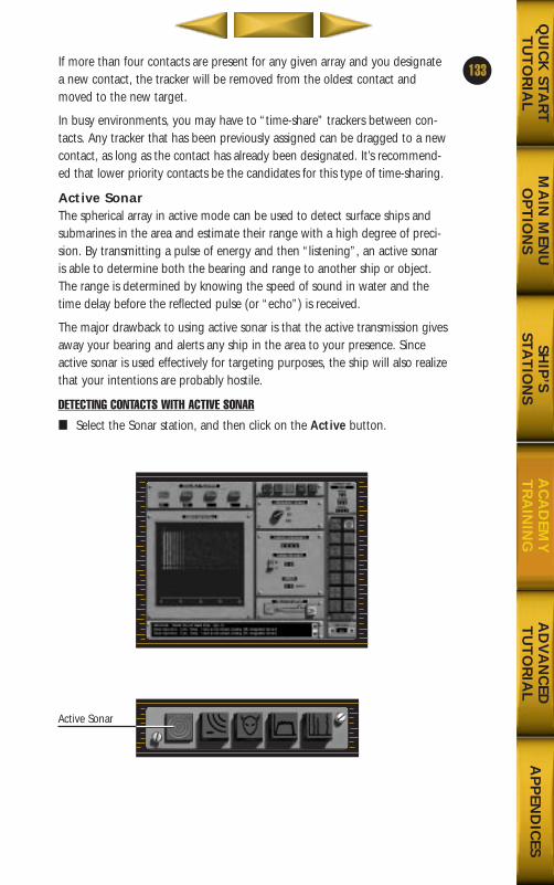
If more than four contacts are present for any given array and you designatea new contact, the tracker will be removed from the oldest contact andmoved to the new target.
In busy environments, you may have to “time-share” trackers between con-tacts. Any tracker that has been previously assigned can be dragged to a newcontact, as long as the contact has already been designated. It’s recommend-ed that lower priority contacts be the candidates for this type of time-sharing.
Active SonarThe spherical array in active mode can be used to detect surface ships andsubmarines in the area and estimate their range with a high degree of preci-sion. By transmitting a pulse of energy and then “listening”, an active sonaris able to determine both the bearing and range to another ship or object.The range is determined by knowing the speed of sound in water and thetime delay before the reflected pulse (or “echo”) is received.
The major drawback to using active sonar is that the active transmission givesaway your bearing and alerts any ship in the area to your presence. Sinceactive sonar is used effectively for targeting purposes, the ship will also realizethat your intentions are probably hostile.
DETECTING CONTACTS WITH ACTIVE SONAR
■ Select the Sonar station, and then click on the Active button.
133
MA
IN M
ENU
OP
TIO
NS
AD
VA
NC
EDT
UT
OR
IAL
AP
PEN
DIC
ESQ
UIC
K STA
RT
TU
TO
RIA
LSH
IP’S
STAT
ION
SA
CA
DEM
YT
RA
ININ
G
Active Sonar
688(i)/AttackSubChptr4 5/6/98 11:14 AM Page 33
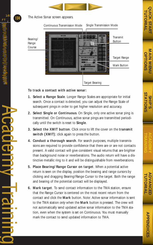
The Active Sonar screen appears.
To track a contact with active sonar:
1. Select a Range Scale. Longer Range Scales are appropriate for initialsearch. Once a contact is detected, you can adjust the Range Scale ofsubsequent pings in order to get higher resolution and accuracy.
2. Select Single or Continuous. On Single, only one active sonar ping istransmitted. On Continuous, active sonar pings are transmitted periodi-cally until the switch is reset to Single.
3. Select the XMIT button. Click once to lift the cover on the transmitswitch (XMIT); click again to press the button.
4. Conduct a thorough search. For search purposes, multiple transmis-sions are required to provide confidence that there are or are not contactspresent. A valid contact will give consistent visual returns that are brighterthan background noise or reverberations. The audio return will have a dis-tinctive metallic ring to it and will be distinguishable from reverberations.
5. Place Bearing/Range Cursor on target. When a potential activereturn is seen on the display, position the bearing and range cursors byclicking and dragging Bearing/Range Cursor to the target. Both the rangeand bearing of the potential contact will be displayed.
6. Mark target. To send contact information to the TMA station, ensurethat the Range Cursor is centered on the most recent return from thecontact and click the Mark button. Note: Active sonar information is sentto the TMA station only when the Mark button is pressed. The crew willnot automatically send updated active sonar information to the TMA sta-tion, even when the system is set on Continuous. You must manuallymark the contact to send updated information to TMA.
FT
180
134
Academy Training
MA
IN M
ENU
OP
TIO
NS
AD
VA
NC
EDT
UT
OR
IAL
AP
PEN
DIC
ESQ
UIC
K STA
RT
TU
TO
RIA
LSH
IP’S
STAT
ION
SA
CA
DEM
YT
RA
ININ
G
Bearing/Range Course
TransmitButton
Target Range
Mark Button
Continuous Transmission Mode
Target Bearing
Single Transmission Mode
688(i)/AttackSubChptr4 5/6/98 11:14 AM Page 34
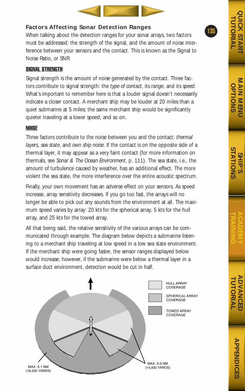
Factors Affecting Sonar Detection RangesWhen talking about the detection ranges for your sonar arrays, two factorsmust be addressed: the strength of the signal, and the amount of noise inter-ference between your sensors and the contact. This is known as the Signal toNoise Ratio, or SNR.
SIGNAL STRENGTH
Signal strength is the amount of noise generated by the contact. Three fac-tors contribute to signal strength: the type of contact, its range, and its speed.What’s important to remember here is that a louder signal doesn’t necessarilyindicate a closer contact. A merchant ship may be louder at 20 miles than aquiet submarine at 5 miles; the same merchant ship would be significantlyquieter traveling at a lower speed; and so on.
NOISE
Three factors contribute to the noise between you and the contact: thermallayers, sea state, and own ship noise. If the contact is on the opposite side of athermal layer, it may appear as a very faint contact (for more information onthermals, see Sonar & The Ocean Environment, p. 111). The sea state, i.e., theamount of turbulence caused by weather, has an additional effect. The moreviolent the sea state, the more interference over the entire acoustic spectrum.
Finally, your own movement has an adverse effect on your sensors. As speedincrease, array sensitivity decreases. If you go too fast, the arrays will nolonger be able to pick out any sounds from the environment at all. The maxi-mum speed varies by array: 20 kts for the spherical array, 5 kts for the hullarray, and 25 kts for the towed array.
All that being said, the relative sensitivity of the various arrays can be com-municated through example. The diagram below depicts a submarine listen-ing to a merchant ship traveling at low speed in a low sea state environment.If the merchant ship were going faster, the sensor ranges displayed belowwould increase; however, if the submarine were below a thermal layer in asurface duct environment, detection would be cut in half.
135
MA
IN M
ENU
OP
TIO
NS
AD
VA
NC
EDT
UT
OR
IAL
AP
PEN
DIC
ESQ
UIC
K STA
RT
TU
TO
RIA
LSH
IP’S
STAT
ION
SA
CA
DEM
YT
RA
ININ
G
MAX. 6.9 NM(14,000 YARDS)MAX. 9.1 NM
(18,500 YARDS)
SPHERICAL ARRAY COVERAGE
HULL ARRAY COVERAGE
TOWED ARRAY COVERAGE
688(i)/AttackSubChptr4 5/6/98 11:14 AM Page 35
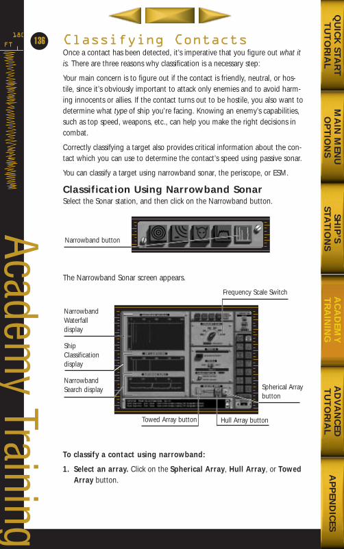
Classifying ContactsOnce a contact has been detected, it’s imperative that you figure out what itis. There are three reasons why classification is a necessary step:
Your main concern is to figure out if the contact is friendly, neutral, or hos-tile, since it’s obviously important to attack only enemies and to avoid harm-ing innocents or allies. If the contact turns out to be hostile, you also want todetermine what type of ship you’re facing. Knowing an enemy’s capabilities,such as top speed, weapons, etc., can help you make the right decisions incombat.
Correctly classifying a target also provides critical information about the con-tact which you can use to determine the contact’s speed using passive sonar.
You can classify a target using narrowband sonar, the periscope, or ESM.
Classification Using Narrowband SonarSelect the Sonar station, and then click on the Narrowband button.
The Narrowband Sonar screen appears.
To classify a contact using narrowband:
1. Select an array. Click on the Spherical Array, Hull Array, or TowedArray button.
FT
180
136
Academy Training
MA
IN M
ENU
OP
TIO
NS
AD
VA
NC
EDT
UT
OR
IAL
AP
PEN
DIC
ESQ
UIC
K STA
RT
TU
TO
RIA
LSH
IP’S
STAT
ION
SA
CA
DEM
YT
RA
ININ
G
Narrowband button
NarrowbandWaterfall display
ShipClassificationdisplay
NarrowbandSearch display Spherical Array
button
Towed Array button Hull Array button
Frequency Scale Switch
688(i)/AttackSubChptr4 5/6/98 11:14 AM Page 36
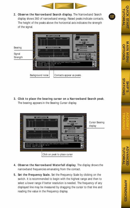
2. Observe the Narrowband Search display. The Narrowband Searchdisplay shows 360 of narrowband energy. Raised peaks indicate contacts.The height of the peaks above the horizontal axis indicates the strengthof the signal.
3. Click to place the bearing cursor on a Narrowband Search peak.The bearing appears in the Bearing Cursor display.
4. Observe the Narrowband Waterfall display. The display shows thenarrowband frequencies emanating from the contact.
5. Set the Frequency Scale. Set the Frequency Scale by clicking on theswitch. It is recommended to begin with the highest range and then toselect a lower range if better resolution is needed. The frequency of anydisplayed line may be measured by dragging the cursor to that line andreading the value in the Frequency display.
137
MA
IN M
ENU
OP
TIO
NS
AD
VA
NC
EDT
UT
OR
IAL
AP
PEN
DIC
ESQ
UIC
K STA
RT
TU
TO
RIA
LSH
IP’S
STAT
ION
SA
CA
DEM
YT
RA
ININ
G
Bearing
SignalStrength
Background noise Contacts appear as peaks
Click on peak to place cursor
Cursor Bearingdisplay
688(i)/AttackSubChptr4 5/6/98 11:14 AM Page 37
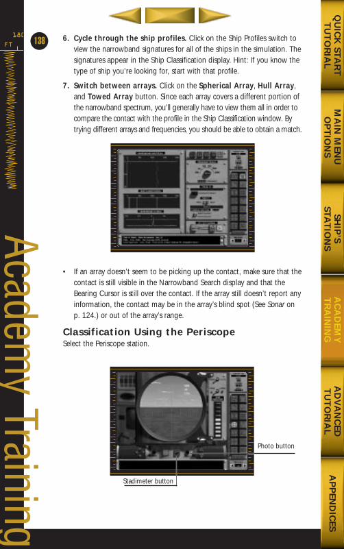
6. Cycle through the ship profiles. Click on the Ship Profiles switch toview the narrowband signatures for all of the ships in the simulation. Thesignatures appear in the Ship Classification display. Hint: If you know thetype of ship you’re looking for, start with that profile.
7. Switch between arrays. Click on the Spherical Array, Hull Array,and Towed Array button. Since each array covers a different portion ofthe narrowband spectrum, you’ll generally have to view them all in order tocompare the contact with the profile in the Ship Classification window. Bytrying different arrays and frequencies, you should be able to obtain a match.
• If an array doesn’t seem to be picking up the contact, make sure that thecontact is still visible in the Narrowband Search display and that theBearing Cursor is still over the contact. If the array still doesn’t report anyinformation, the contact may be in the array’s blind spot (See Sonar on p. 124.) or out of the array’s range.
Classification Using the PeriscopeSelect the Periscope station.
FT
180
138
Academy Training
MA
IN M
ENU
OP
TIO
NS
AD
VA
NC
EDT
UT
OR
IAL
AP
PEN
DIC
ESQ
UIC
K STA
RT
TU
TO
RIA
LSH
IP’S
STAT
ION
SA
CA
DEM
YT
RA
ININ
G
Photo button
Stadimeter button
688(i)/AttackSubChptr4 5/6/98 11:14 AM Page 38
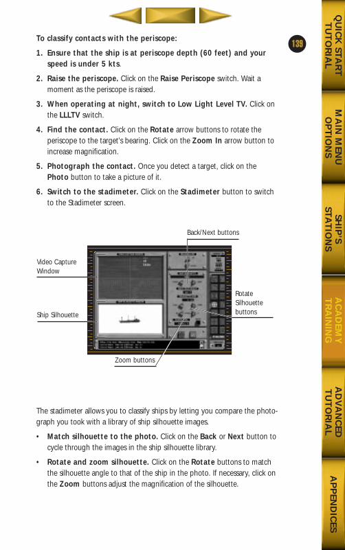
To classify contacts with the periscope:
1. Ensure that the ship is at periscope depth (60 feet) and yourspeed is under 5 kts.
2. Raise the periscope. Click on the Raise Periscope switch. Wait amoment as the periscope is raised.
3. When operating at night, switch to Low Light Level TV. Click onthe LLLTV switch.
4. Find the contact. Click on the Rotate arrow buttons to rotate theperiscope to the target’s bearing. Click on the Zoom In arrow button toincrease magnification.
5. Photograph the contact. Once you detect a target, click on thePhoto button to take a picture of it.
6. Switch to the stadimeter. Click on the Stadimeter button to switchto the Stadimeter screen.
The stadimeter allows you to classify ships by letting you compare the photo-graph you took with a library of ship silhouette images.
• Match silhouette to the photo. Click on the Back or Next button tocycle through the images in the ship silhouette library.
• Rotate and zoom silhouette. Click on the Rotate buttons to matchthe silhouette angle to that of the ship in the photo. If necessary, click onthe Zoom buttons adjust the magnification of the silhouette.
139
MA
IN M
ENU
OP
TIO
NS
AD
VA
NC
EDT
UT
OR
IAL
AP
PEN
DIC
ESQ
UIC
K STA
RT
TU
TO
RIA
LSH
IP’S
STAT
ION
SA
CA
DEM
YT
RA
ININ
G
Video CaptureWindow
Ship Silhouette
RotateSilhouette buttons
Zoom buttons
Back/Next buttons
688(i)/AttackSubChptr4 5/6/98 11:14 AM Page 39
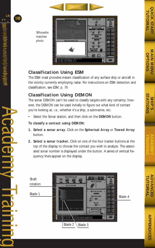
Classification Using ESMThe ESM mast provides instant classification of any surface ship or aircraft inthe vicinity currently employing radar. For instructions on ESM detection andclassification, see ESM, p. 76
Classification Using DEMONThe sonar DEMON can’t be used to classify targets with any certainty; how-ever, the DEMON can be used initially to figure out what kind of contactyou’re looking at, i.e., whether it’s a ship, a submarine, etc.
• Select the Sonar station, and then click on the DEMON button.
To classify a contact using DEMON:
1. Select a sonar array. Click on the Spherical Array or Towed Arraybutton.
2. Select a sonar tracker. Click on one of the four tracker buttons at thetop of the display to choose the contact you wish to analyze. The associ-ated sonar number is displayed under the button. A series of vertical fre-quency lines appear on the display.
FT
180
140
Academy Training
MA
IN M
ENU
OP
TIO
NS
AD
VA
NC
EDT
UT
OR
IAL
AP
PEN
DIC
ESQ
UIC
K STA
RT
TU
TO
RIA
LSH
IP’S
STAT
ION
SA
CA
DEM
YT
RA
ININ
G
Silhouettematchesphoto
Shaft rotation
Blade 1Blade 4
Blade 2 Blade 3
688(i)/AttackSubChptr4 5/6/98 11:14 AM Page 40
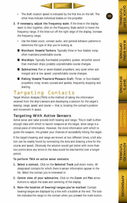
• The shaft rotation speed is indicated by the first line on the left. Theother lines indicate individual blades on the propeller.
3. If necessary, adjust the frequency scale. If the lines in the displayseem to blur together, click on the Frequency Scale switch to lower thefrequency range, if the lines run off the right edge of the display, increasethe frequency range.
• Use the blade count, contact audio, and general behavior patterns todetermine the type of ship you’re looking at.
■ Merchant Vessels/Tankers: Typically three or four blades; noisy;often maintains predictable course.
■ Warships: Typically five-bladed propellers; quieter, smoother soundthan merchant ships; possibly unpredictable course changes.
■ Submarines: Five or seven-bladed propellers; very quiet when sub-merged and at low speed; unpredictable course changes.
■ Fishing Vessels/Trawlers/Pleasure Craft: Three- or four-bladedpropellers; noisy; erratic courses and speeds, frequently stopping andstarting.
Targeting ContactsTarget Motion Analysis (TMA) is the method of taking the informationreceived from the ship’s sensors and developing a solution for the target’sbearing, range, speed, and course — that is, locating the contact’s positionand movement in space.
Targeting With Active SensorsActive sonar and radar provide both bearing and range. This in itself is oftenenough data with which to launch weapons at the target, since range is acritical piece of information. However, the more information with which toguide the weapon, the greater your chances of successfully hitting the target.
If the target’s bearing and range are known at two different times, a full solu-tion can be readily found by connecting the dots and drawing a line for thecourse and speed. Obviously the solution would get better with more thantwo points since any errors in the data would be less harmful over a longerperiod.
To perform TMA on active sonar contacts:
1. Select a contact. Click on the Selected Track pull-down menu. Alldesignated contacts for which there is sensor information appear in thelist. Select the contact you’re interested in.
2. Center view of your submarine. Click on the Zoom and Pan arrowbuttons to adjust the scale and centering of the display.
3. Note the location of bearing/ranges you’ve marked. Contactbearing/ranges are displayed by a line with a bubble at the end. The bub-ble indicates the range to the contact when you pressed the mark button.
141
MA
IN M
ENU
OP
TIO
NS
AD
VA
NC
EDT
UT
OR
IAL
AP
PEN
DIC
ESQ
UIC
K STA
RT
TU
TO
RIA
LSH
IP’S
STAT
ION
SA
CA
DEM
YT
RA
ININ
G
688(i)/AttackSubChptr4 5/6/98 11:14 AM Page 41
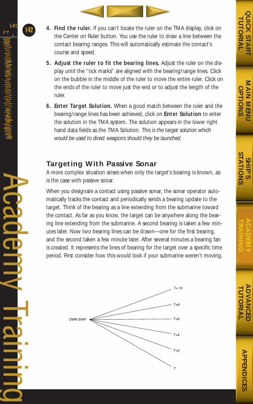
4. Find the ruler. If you can’t locate the ruler on the TMA display, click onthe Center on Ruler button. You use the ruler to draw a line between thecontact bearing ranges. This will automatically estimate the contact’scourse and speed.
5. Adjust the ruler to fit the bearing lines. Adjust the ruler on the dis-play until the “tick marks” are aligned with the bearing/range lines. Clickon the bubble in the middle of the ruler to move the entire ruler. Click onthe ends of the ruler to move just the end or to adjust the length of theruler.
6. Enter Target Solution. When a good match between the ruler and thebearing/range lines has been achieved, click on Enter Solution to enterthe solution in the TMA system. The solution appears in the lower righthand data fields as the TMA Solution. This is the target solution whichwould be used to direct weapons should they be launched.
Targeting With Passive SonarA more complex situation arises when only the target’s bearing is known, asis the case with passive sonar.
When you designate a contact using passive sonar, the sonar operator auto-matically tracks the contact and periodically sends a bearing update to thetarget. Think of the bearing as a line extending from the submarine towardthe contact. As far as you know, the target can be anywhere along the bear-ing line extending from the submarine. A second bearing is taken a few min-utes later. Now two bearing lines can be drawn—one for the first bearing,and the second taken a few minute later. After several minutes a bearing fanis created. It represents the lines of bearing for the target over a specific timeperiod. First consider how this would look if your submarine weren’t moving.
FT
180
142
Academy Training
MA
IN M
ENU
OP
TIO
NS
AD
VA
NC
EDT
UT
OR
IAL
AP
PEN
DIC
ESQ
UIC
K STA
RT
TU
TO
RIA
LSH
IP’S
STAT
ION
SA
CA
DEM
YT
RA
ININ
G
T+ 10
T+8
T+6
T+4
OWN SHIP
T+2
T
688(i)/AttackSubChptr4 5/6/98 11:15 AM Page 42
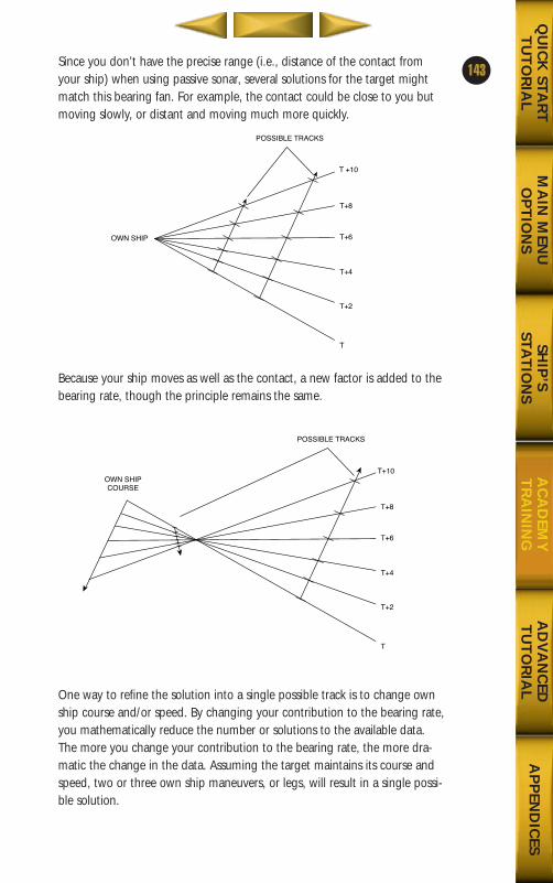
Since you don’t have the precise range (i.e., distance of the contact fromyour ship) when using passive sonar, several solutions for the target mightmatch this bearing fan. For example, the contact could be close to you butmoving slowly, or distant and moving much more quickly.
Because your ship moves as well as the contact, a new factor is added to thebearing rate, though the principle remains the same.
One way to refine the solution into a single possible track is to change ownship course and/or speed. By changing your contribution to the bearing rate,you mathematically reduce the number or solutions to the available data.The more you change your contribution to the bearing rate, the more dra-matic the change in the data. Assuming the target maintains its course andspeed, two or three own ship maneuvers, or legs, will result in a single possi-ble solution.
143
MA
IN M
ENU
OP
TIO
NS
AD
VA
NC
EDT
UT
OR
IAL
AP
PEN
DIC
ESQ
UIC
K STA
RT
TU
TO
RIA
LSH
IP’S
STAT
ION
SA
CA
DEM
YT
RA
ININ
G
T +10
T+8
T+6
T+4
OWN SHIP
POSSIBLE TRACKS
T+2
T
T+10
T+8
T+6
T+4
POSSIBLE TRACKS
T+2
T
OWN SHIPCOURSE
688(i)/AttackSubChptr4 5/6/98 11:15 AM Page 43
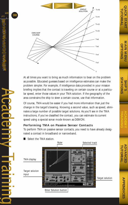
At all times you want to bring as much information to bear on the problemas possible. Educated guesses based on intelligence estimates can make theproblem simpler. For example, if intelligence data provided in your missionbriefing implies that the contact is traveling on certain course or at a particu-lar speed, enter those values in your TMA solution. If the geography of thearea constrains the ship to steer a certain course, use that information.
Of course, TMA would be easier if you had more information than just thechange in the target’s bearing. Knowing a second value, such as speed, elimi-nates a large number of possible target solutions. As you’ll see in the TMAinstructions, if you’ve classified the contact, you can estimate its currentspeed using a special sonar mode known as DEMON.
Performing TMA on Passive Sensor ContactsTo perform TMA on passive sensor contacts, you need to have already desig-nated a contact in broadband or narrowband.
■ Select the TMA station.
FT
180
144
Academy Training
T+10
T+8
T+6
T+4
SINGLESOLUTION
T+2
T
OWN SHIPCOURSE
T+12
T+14
T+16
TMA display
Target solutioninput
Target solution
Enter Solution button
Selected trackRuler
MA
IN M
ENU
OP
TIO
NS
AD
VA
NC
EDT
UT
OR
IAL
AP
PEN
DIC
ESQ
UIC
K STA
RT
TU
TO
RIA
LSH
IP’S
STAT
ION
SA
CA
DEM
YT
RA
ININ
G
688(i)/AttackSubChptr4 5/6/98 11:15 AM Page 44
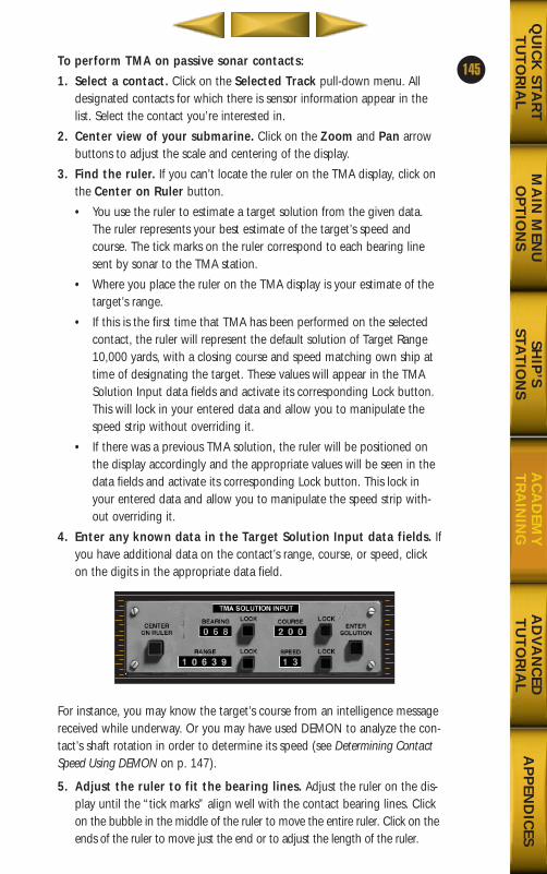
To perform TMA on passive sonar contacts:
1. Select a contact. Click on the Selected Track pull-down menu. Alldesignated contacts for which there is sensor information appear in thelist. Select the contact you’re interested in.
2. Center view of your submarine. Click on the Zoom and Pan arrowbuttons to adjust the scale and centering of the display.
3. Find the ruler. If you can’t locate the ruler on the TMA display, click onthe Center on Ruler button.
• You use the ruler to estimate a target solution from the given data.The ruler represents your best estimate of the target’s speed andcourse. The tick marks on the ruler correspond to each bearing linesent by sonar to the TMA station.
• Where you place the ruler on the TMA display is your estimate of thetarget’s range.
• If this is the first time that TMA has been performed on the selectedcontact, the ruler will represent the default solution of Target Range10,000 yards, with a closing course and speed matching own ship attime of designating the target. These values will appear in the TMASolution Input data fields and activate its corresponding Lock button.This will lock in your entered data and allow you to manipulate thespeed strip without overriding it.
• If there was a previous TMA solution, the ruler will be positioned onthe display accordingly and the appropriate values will be seen in thedata fields and activate its corresponding Lock button. This lock inyour entered data and allow you to manipulate the speed strip with-out overriding it.
4. Enter any known data in the Target Solution Input data fields. Ifyou have additional data on the contact’s range, course, or speed, clickon the digits in the appropriate data field.
For instance, you may know the target’s course from an intelligence messagereceived while underway. Or you may have used DEMON to analyze the con-tact’s shaft rotation in order to determine its speed (see Determining ContactSpeed Using DEMON on p. 147).
5. Adjust the ruler to fit the bearing lines. Adjust the ruler on the dis-play until the “tick marks” align well with the contact bearing lines. Clickon the bubble in the middle of the ruler to move the entire ruler. Click on theends of the ruler to move just the end or to adjust the length of the ruler.
145
MA
IN M
ENU
OP
TIO
NS
AD
VA
NC
EDT
UT
OR
IAL
AP
PEN
DIC
ESQ
UIC
K STA
RT
TU
TO
RIA
LSH
IP’S
STAT
ION
SA
CA
DEM
YT
RA
ININ
G
688(i)/AttackSubChptr4 5/6/98 11:15 AM Page 45
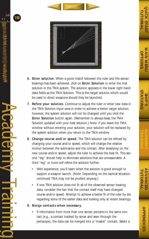
6. Enter solution. When a good match between the ruler and the sensorbearings has been achieved, click on Enter Solution to enter the trialsolution in the TMA system. The solution appears in the lower right handdata fields as the TMA Solution. This is the target solution which wouldbe used to direct weapons should they be launched.
7. Refine your solution. Continue to adjust the ruler or enter new data inthe TMA Solution Input area in order to achieve a better target solution;however, the system solution will not be changed until you click theEnter Solution button again. (Remember to always keep the TMASolution updated with your best solution.) Note: if you leave the TMAwindow without entering your solution, your solution will be replaced bythe system solution when you return to the TMA window.
8. Change course and/or speed. The TMA solution can be refined bychanging your course and/or speed, which will change the relativemotion between the submarine and the contact. After steadying on thenew course and/or speed, adjust the ruler to achieve the best fit. This sec-ond “leg” should help to eliminate solutions that are unreasonable. Athird “leg” or more will refine the solution further.
• With experience, you’ll learn when the solution is good enough tosupport a weapon launch. (Note: Depending on the tactical situation,continued TMA may not be prudent anyway.)
• If one TMA solution does not fit all of the observed sensor bearingdata, consider the fact that the contact itself may have changedcourse and/or speed. Attempt to achieve a better fit of the ruler by dis-regarding some of the earlier data and looking only at recent bearings.
9. Merge contacts when necessary.
• If information from more than one sensor pertains to the same con-tact (e.g., a contact tracked by sonar and seen through theperiscope), the data can be merged into a “master” contact. Select a
FT
180
146
Academy Training
MA
IN M
ENU
OP
TIO
NS
AD
VA
NC
EDT
UT
OR
IAL
AP
PEN
DIC
ESQ
UIC
K STA
RT
TU
TO
RIA
LSH
IP’S
STAT
ION
SA
CA
DEM
YT
RA
ININ
G
688(i)/AttackSubChptr4 5/6/98 11:15 AM Page 46
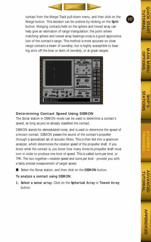
contact from the Merge Track pull-down menu, and then click on theMerge button. This decision can be undone by clicking on the Splitbutton. Merging contacts held on the sphere and towed array canhelp give an estimation of range triangulation: the point wherematching sphere and towed array bearings cross is a good approxima-tion of the contact’s range. This method is most accurate on closerange contacts a beam of ownship, but is highly susceptible to bear-ing error off the bow or stern of ownship, or at great ranges.
Determining Contact Speed Using DEMONThe Sonar station in DEMON mode can be used to determine a contact’sspeed, so long as you’ve already classified the contact.
DEMON stands for demodulated noise, and is used to determine the speed ofa known contact. DEMON passes the sound of the contact’s propellerthrough a specialized set of acoustic filters. This is then fed into a spectrumanalyzer, which determines the rotation speed of the propeller shaft. If youknow what the contact is, you know how many times its propeller shaft mustturn in order to produce one knot of speed. This is called turns per knot, orTPK. The two together—rotation speed and turns per knot - provide you witha fairly precise measurement of target speed.
■ Select the Sonar station, and then click on the DEMON button.
To analyze a contact using DEMON:
1. Select a sonar array. Click on the Spherical Array or Towed Arraybutton.
147
MA
IN M
ENU
OP
TIO
NS
AD
VA
NC
EDT
UT
OR
IAL
AP
PEN
DIC
ESQ
UIC
K STA
RT
TU
TO
RIA
LSH
IP’S
STAT
ION
SA
CA
DEM
YT
RA
ININ
G
688(i)/AttackSubChptr4 5/6/98 11:15 AM Page 47
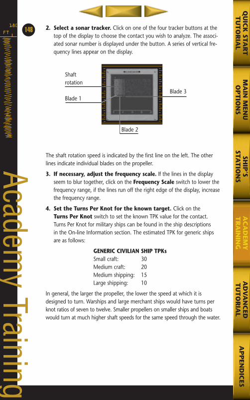
2. Select a sonar tracker. Click on one of the four tracker buttons at thetop of the display to choose the contact you wish to analyze. The associ-ated sonar number is displayed under the button. A series of vertical fre-quency lines appear on the display.
The shaft rotation speed is indicated by the first line on the left. The otherlines indicate individual blades on the propeller.
3. If necessary, adjust the frequency scale. If the lines in the displayseem to blur together, click on the Frequency Scale switch to lower thefrequency range, if the lines run off the right edge of the display, increasethe frequency range.
4. Set the Turns Per Knot for the known target. Click on the Turns Per Knot switch to set the known TPK value for the contact.Turns Per Knot for military ships can be found in the ship descriptions in the On-line Information section. The estimated TPK for generic shipsare as follows:
GENERIC CIVILIAN SHIP TPKsSmall craft: 30Medium craft: 20Medium shipping: 15Large shipping: 10
In general, the larger the propeller, the lower the speed at which it isdesigned to turn. Warships and large merchant ships would have turns perknot ratios of seven to twelve. Smaller propellers on smaller ships and boatswould turn at much higher shaft speeds for the same speed through the water.
FT
180148
Academy Training
MA
IN M
ENU
OP
TIO
NS
AD
VA
NC
EDT
UT
OR
IAL
AP
PEN
DIC
ESQ
UIC
K STA
RT
TU
TO
RIA
LSH
IP’S
STAT
ION
SA
CA
DEM
YT
RA
ININ
G
Shaftrotation
Blade 1Blade 3
Blade 2
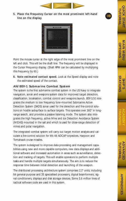
5. Place the Frequency Cursor on the most prominent left-handline on the display.
Point the mouse cursor at the right edge of the most prominent line on theleft and click. This will be the shaft line. The frequency will be displayed inthe Cursor Frequency display. (Shaft RPM can be calculated by multiplyingthis frequency by 60.)
6. Note estimated contact speed. Look at the Speed display and notethe estimated speed of the contact.
AN/BSY-1 Submarine Combat SystemThe system is the first submarine combat system in the US Navy to integratenavigation, sonar and weapons system data for improved target detection,classification, localisation, combat control and weapons launch. BSY-1(V) inte-grates the medium to low frequency bow-mounted Submarine ActiveDetection System (SADS) sonar used for the detection and fire-control solu-tions on hostile subsurface to surface targets. This operates over 360° in long-range search, and provides a passive listening mode. The system also inte-grates the high frequency, active Mine and Ice Detection Avoidance System(MIDAS) mounted in the sail and which is used for close-range detection ofmines and polar navigation.
The integrated combat system will carry out target motion analysis and cal-culate a fire-control solution for Mk 48 ADCAP torpedoes, Harpoon andTomahawk cruise missiles.
The system is designed to improve data processing and management capa-bilities using new and more capable computers, new data displays and addi-tional software and increased automation in areas such as surveillance, detec-tion and tracking of targets. This will enable operators to perform multipletasks and handle multiple targets simultaneously. The aim is to reduce theresponse time between initial detection and launching of the weapon.
The distributed processing architecture system comprises 117 units, including64 general-purpose and 35 specialised processors, digital beamformers, sig-nal conditioners, displays and disk storage devices. Some 3.6 million lines oftactical software code are used in this system.
149
MA
IN M
ENU
OP
TIO
NS
AD
VA
NC
EDT
UT
OR
IAL
AP
PEN
DIC
ESQ
UIC
K STA
RT
TU
TO
RIA
LSH
IP’S
STAT
ION
SA
CA
DEM
YT
RA
ININ
G
688(i)/AttackSubChptr4 5/6/98 11:15 AM Page 49
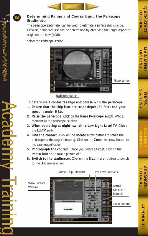
Determining Range and Course Using the PeriscopeStadimeterThe periscope stadimeter can be used to estimate a surface ship’s range.Likewise, a ship’s course can be determined by observing the target aspect orangle on the bow (AOB).
Select the Periscope station.
To determine a contact’s range and course with the periscope:1. Ensure that the ship is at periscope depth (60 feet) and your
speed is under 5 kts.2. Raise the periscope. Click on the Raise Periscope switch. Wait a
moment as the periscope is raised.3. When operating at night, switch to Low Light Level TV. Click on
the LLLTV switch.4. Find the contact. Click on the Rotate arrow buttons to rotate the
periscope to the target’s bearing. Click on the Zoom In arrow button toincrease magnification.
5. Photograph the contact. Once you detect a target, click on thePhoto button to take a picture of it.
6. Switch to the stadimeter. Click on the Stadimeter button to switchto the Stadimeter screen.
FT
180
150
Academy Training
MA
IN M
ENU
OP
TIO
NS
AD
VA
NC
EDT
UT
OR
IAL
AP
PEN
DIC
ESQ
UIC
K STA
RT
TU
TO
RIA
LSH
IP’S
STAT
ION
SA
CA
DEM
YT
RA
ININ
G
Photo button
Stadimeter button
Video CaptureWindow Rotate
Silhouettebuttons
Zoom buttons
Back/Next buttonsCurrent Ship Silhouette
688(i)/AttackSubChptr4 5/6/98 11:15 AM Page 50
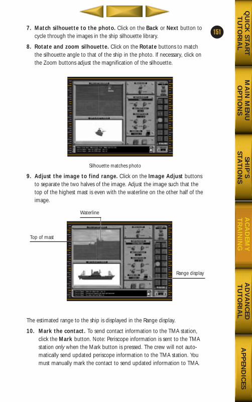
7. Match silhouette to the photo. Click on the Back or Next button tocycle through the images in the ship silhouette library.
8. Rotate and zoom silhouette. Click on the Rotate buttons to matchthe silhouette angle to that of the ship in the photo. If necessary, click onthe Zoom buttons adjust the magnification of the silhouette.
Silhouette matches photo
9. Adjust the image to find range. Click on the Image Adjust buttonsto separate the two halves of the image. Adjust the image such that thetop of the highest mast is even with the waterline on the other half of theimage.
The estimated range to the ship is displayed in the Range display.
10. Mark the contact. To send contact information to the TMA station,click the Mark button. Note: Periscope information is sent to the TMAstation only when the Mark button is pressed. The crew will not auto-matically send updated periscope information to the TMA station. Youmust manually mark the contact to send updated information to TMA.
151
MA
IN M
ENU
OP
TIO
NS
AD
VA
NC
EDT
UT
OR
IAL
AP
PEN
DIC
ESQ
UIC
K STA
RT
TU
TO
RIA
LSH
IP’S
STAT
ION
SA
CA
DEM
YT
RA
ININ
G
Top of mast
Range display
Waterline
688(i)/AttackSubChptr4 5/6/98 11:15 AM Page 51
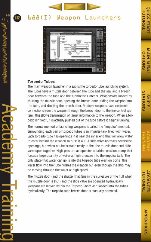
688(I) Weapon Launchers
Torpedo TubesThe main weapon launcher in a sub is the torpedo tube launching system.The tubes have a muzzle door between the tube and the sea, and a breechdoor between the tube and the submarine’s interior. Weapons are loaded byshutting the muzzle door, opening the breech door, sliding the weapon intothe tube, and shutting the breech door. Modern weapons have electronicconnections from the weapon through the breech door to the fire control sys-tem. This allows transmission of target information to the weapon. When a tor-pedo is “fired”, it is actually pushed out of the tube before it begins running.
The normal method of launching weapons is called the “impulse” method.Surrounding each pair of torpedo tubes is an impulse tank filled with water.Each torpedo tube has openings in it near the inner end that will allow waterto enter behind the weapon to push it out. A slide valve normally covers theopenings, but when a tube is made ready to fire, the muzzle door and slidevalve open together. High pressure air operates a turbine ejection pump thatforces a large quantity of water at high pressure into the impulse tank. Theonly place that water can go is into the torpedo tube ejection ports. Thiswater flow into the tube flushes the weapon out even though the ship maybe moving through the water at high speed.
The muzzle door (and the shutter that fairs in the curvature of the hull whenthe muzzle door is shut) and the slide valve are operated hydraulically.Weapons are moved within the Torpedo Room and loaded into the tubeshydraulically. The torpedo tube breech door is manually operated.
FT
180
152
Academy Training
MA
IN M
ENU
OP
TIO
NS
AD
VA
NC
EDT
UT
OR
IAL
AP
PEN
DIC
ESQ
UIC
K STA
RT
TU
TO
RIA
LSH
IP’S
STAT
ION
SA
CA
DEM
YT
RA
ININ
G
688(i)/AttackSubChptr4 5/6/98 11:15 AM Page 52
There are four horizontal torpedo tubes, two on each side of the ship.Because of the large sonar sphere at the bow, the torpedo tubes are angledoutward slightly.
Vertical Launch TubesVertical launchers for TLAMs (Tomahawk Land Attack Missile) work differently.They are loaded at the pier and cannot be reloaded once the boat is under-way. (Hence, the importance of a thorough briefing, with weapon require-ments. If you are out at sea and haven’t loaded enough TLAMs, there’s noth-ing you can do.) The vertical launch tube is pressurized with air, using adiaphragm at its top as a boundary to the sea. The muzzle door is thenopened. When fired, a solid propellant gas generator produces the gas thatforces the missile from the tube. Once clear, the missile ignites, beginning itsflight toward its target.
Eight Los Angeles class submarines and 23 Improved Los Angeles class sub-marines have twelve vertical launch tubes installed at the bow. This wasmade possible by a redesign of the forward main ballast tank structure andthe air banks located there.
Signal EjectorSimilar in principal to the torpedo tubes, the signal ejector is actually a two-barreled installation. Located on the port side of the middle level of theForward Compartment, there are two three-inch diameter tubes that areused to launch a variety of pyrotechnic signals, countermeasures, anddecoys.
153
MA
IN M
ENU
OP
TIO
NS
AD
VA
NC
EDT
UT
OR
IAL
AP
PEN
DIC
ESQ
UIC
K STA
RT
TU
TO
RIA
LSH
IP’S
STAT
ION
SA
CA
DEM
YT
RA
ININ
G
688(i)/AttackSubChptr4 5/6/98 11:15 AM Page 53
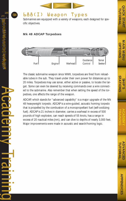
688(I) Weapon TypesSubmarines are equipped with a variety of weapons, each designed for spe-cific objectives.
Mk 48 ADCAP Torpedoes
The classic submarine weapon since WWII, torpedoes are fired from reload-able tubes in the sub. They travel under their own power for distances up to20 miles. Torpedoes may use sonar, either active or passive, to locate the tar-get. Some can even be steered by receiving commands over a wire connect-ed to the submarine. Also remember that when setting the speed of the tor-pedoes, one affects the range of the weapon.
ADCAP, which stands for “advanced capability” is a major upgrade of the Mk48 heavyweight torpedo. ADCAP is a wire-guided, acoustic homing torpedothat is propelled by the combustion of a monopropellant fuel (self-oxidizingfuel). ADCAP is 21 inches in diameter, carries a warhead in excess of 500pounds of high explosive, can reach speeds of 55 knots, has a range inexcess of 20 nautical miles (nm), and can dive to depths of nearly 3,000 feet.Major improvements were made in acoustic and search/homing logic.
FT
180
154
Academy Training
MA
IN M
ENU
OP
TIO
NS
AD
VA
NC
EDT
UT
OR
IAL
AP
PEN
DIC
ESQ
UIC
K STA
RT
TU
TO
RIA
LSH
IP’S
STAT
ION
SA
CA
DEM
YT
RA
ININ
G
Fuel EngineSonarSeeker
GuidanceControlWarhead
688(i)/AttackSubChptr4 5/6/98 11:15 AM Page 54
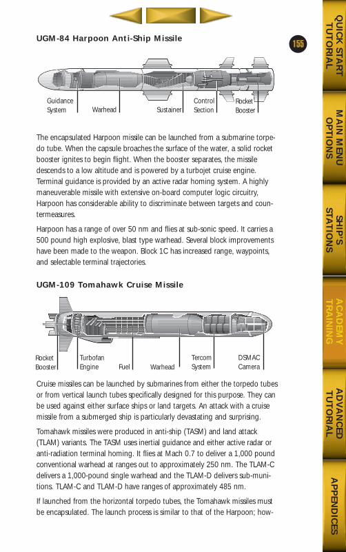
UGM-84 Harpoon Anti-Ship Missile
The encapsulated Harpoon missile can be launched from a submarine torpe-do tube. When the capsule broaches the surface of the water, a solid rocketbooster ignites to begin flight. When the booster separates, the missiledescends to a low altitude and is powered by a turbojet cruise engine.Terminal guidance is provided by an active radar homing system. A highlymaneuverable missile with extensive on-board computer logic circuitry,Harpoon has considerable ability to discriminate between targets and coun-termeasures.
Harpoon has a range of over 50 nm and flies at sub-sonic speed. It carries a500 pound high explosive, blast type warhead. Several block improvementshave been made to the weapon. Block 1C has increased range, waypoints,and selectable terminal trajectories.
UGM-109 Tomahawk Cruise Missile
Cruise missiles can be launched by submarines from either the torpedo tubesor from vertical launch tubes specifically designed for this purpose. They canbe used against either surface ships or land targets. An attack with a cruisemissile from a submerged ship is particularly devastating and surprising.
Tomahawk missiles were produced in anti-ship (TASM) and land attack(TLAM) variants. The TASM uses inertial guidance and either active radar oranti-radiation terminal homing. It flies at Mach 0.7 to deliver a 1,000 poundconventional warhead at ranges out to approximately 250 nm. The TLAM-Cdelivers a 1,000-pound single warhead and the TLAM-D delivers sub-muni-tions. TLAM-C and TLAM-D have ranges of approximately 485 nm.
If launched from the horizontal torpedo tubes, the Tomahawk missiles mustbe encapsulated. The launch process is similar to that of the Harpoon; how-
155
MA
IN M
ENU
OP
TIO
NS
AD
VA
NC
EDT
UT
OR
IAL
AP
PEN
DIC
ESQ
UIC
K STA
RT
TU
TO
RIA
LSH
IP’S
STAT
ION
SA
CA
DEM
YT
RA
ININ
G
GuidanceSystem Warhead
RocketBooster
ControlSectionSustainer
RocketBooster
TurbofanEngine
DSMACCameraWarheadFuel
TercomSystem
688(i)/AttackSubChptr4 5/6/98 11:15 AM Page 55
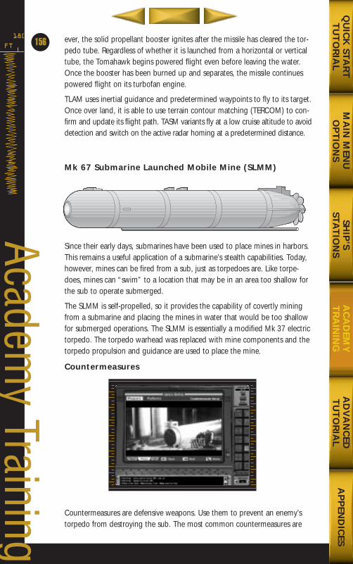
ever, the solid propellant booster ignites after the missile has cleared the tor-pedo tube. Regardless of whether it is launched from a horizontal or verticaltube, the Tomahawk begins powered flight even before leaving the water.Once the booster has been burned up and separates, the missile continuespowered flight on its turbofan engine.
TLAM uses inertial guidance and predetermined waypoints to fly to its target.Once over land, it is able to use terrain contour matching (TERCOM) to con-firm and update its flight path. TASM variants fly at a low cruise altitude to avoiddetection and switch on the active radar homing at a predetermined distance.
Mk 67 Submarine Launched Mobile Mine (SLMM)
Since their early days, submarines have been used to place mines in harbors.This remains a useful application of a submarine’s stealth capabilities. Today,however, mines can be fired from a sub, just as torpedoes are. Like torpe-does, mines can “swim” to a location that may be in an area too shallow forthe sub to operate submerged.
The SLMM is self-propelled, so it provides the capability of covertly miningfrom a submarine and placing the mines in water that would be too shallowfor submerged operations. The SLMM is essentially a modified Mk 37 electrictorpedo. The torpedo warhead was replaced with mine components and thetorpedo propulsion and guidance are used to place the mine.
Countermeasures
Countermeasures are defensive weapons. Use them to prevent an enemy’storpedo from destroying the sub. The most common countermeasures are
FT
180
156
Academy Training
MA
IN M
ENU
OP
TIO
NS
AD
VA
NC
EDT
UT
OR
IAL
AP
PEN
DIC
ESQ
UIC
K STA
RT
TU
TO
RIA
LSH
IP’S
STAT
ION
SA
CA
DEM
YT
RA
ININ
G
688(i)/AttackSubChptr4 5/6/98 11:15 AM Page 56

launched from the submarine and remain in the location where they arelaunched. A Jammer raises the noise level between the torpedo and your sub-marine, creating a fog bank that inhibits a torpedo’s active sonar ability. ADecoy emits a signal designed to draw the enemy torpedo away from thesub and toward the decoy. Both types of countermeasure can be preset tostay deep or shallow.
Launching WeaponsOne of your primary objectives is to seek out and destroy enemy ships,weapons, and strongholds.
Preparations can be lengthy and noisy, so it is a good idea to have tubesloaded, flooded, and equalized and have muzzle doors open before comingwithin the detection range of the enemy. It takes several people to load a tor-pedo and connect both the A-cable (which gives the torpedo its presets andorders before launch) and the guidance wire (which can be used after thelaunch). The torpedo should also be checked to ensure that it properlyreceives commands.
A torpedo can be impulse launched up to the maximum speed of the subma-rine as long as the ship is on a steady course and the trim angle is no morethan a few degrees above or below the horizontal (“zero bubble”).
Launching Missiles HorizontallyAdvanced preparations are advised but not for the same reasons. Whenlaunching a missile, the enemy is probably farther away so noise is not asmuch of a consideration. Being ready to launch is important so that coordi-nated strikes can be initiated when the operational situation dictates.
Harpoon and Tomahawk missiles should be launched at low speeds (e.g., 4knots or less) and at shallow depths (e.g., keel depth of 150 feet or less). If atperiscope depth, it is possible to confirm that the missile is flying normally.
Vertical Launch of MissilesThe vertical launchers have to be loaded in port, so the preparation consistsonly of pressurizing the tubes and opening the hatches. Targeting informa-tion also has to be sent to the missile prior to launch. Speed and depth limitsare the same as for the horizontal launch of missiles.
ADCAP Torpedo LaunchThe ADCAP torpedo, the U.S. Navy’s heavy-weight torpedo, can be usedagainst submarines and surface ships. It is a wire-guided, acoustically homingtorpedo carrying a warhead of more than 500 lbs. of high explosive andcapable of speeds up to 55 knots. It has a maximum range in excess of 20nautical miles.
The ADCAP is launched from a horizontal torpedo tube. Prior to launch, thetorpedo is loaded into the tube, and the A-cable and guidance wire are con-
157
MA
IN M
ENU
OP
TIO
NS
AD
VA
NC
EDT
UT
OR
IAL
AP
PEN
DIC
ESQ
UIC
K STA
RT
TU
TO
RIA
LSH
IP’S
STAT
ION
SA
CA
DEM
YT
RA
ININ
G
688(i)/AttackSubChptr4 5/6/98 11:15 AM Page 57
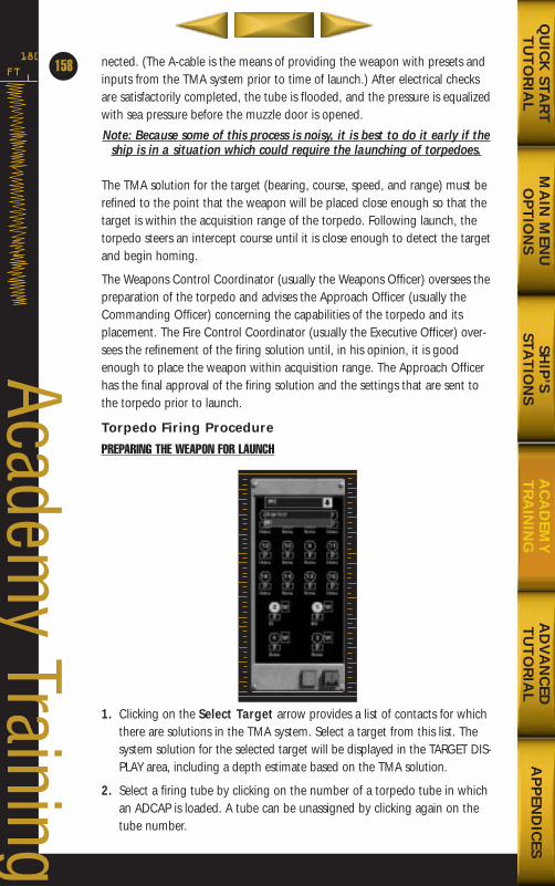
nected. (The A-cable is the means of providing the weapon with presets andinputs from the TMA system prior to time of launch.) After electrical checksare satisfactorily completed, the tube is flooded, and the pressure is equalizedwith sea pressure before the muzzle door is opened.
Note: Because some of this process is noisy, it is best to do it early if theship is in a situation which could require the launching of torpedoes.
The TMA solution for the target (bearing, course, speed, and range) must berefined to the point that the weapon will be placed close enough so that thetarget is within the acquisition range of the torpedo. Following launch, thetorpedo steers an intercept course until it is close enough to detect the targetand begin homing.
The Weapons Control Coordinator (usually the Weapons Officer) oversees thepreparation of the torpedo and advises the Approach Officer (usually theCommanding Officer) concerning the capabilities of the torpedo and itsplacement. The Fire Control Coordinator (usually the Executive Officer) over-sees the refinement of the firing solution until, in his opinion, it is goodenough to place the weapon within acquisition range. The Approach Officerhas the final approval of the firing solution and the settings that are sent tothe torpedo prior to launch.
Torpedo Firing Procedure
PREPARING THE WEAPON FOR LAUNCH
1. Clicking on the Select Target arrow provides a list of contacts for whichthere are solutions in the TMA system. Select a target from this list. Thesystem solution for the selected target will be displayed in the TARGET DIS-PLAY area, including a depth estimate based on the TMA solution.
2. Select a firing tube by clicking on the number of a torpedo tube in whichan ADCAP is loaded. A tube can be unassigned by clicking again on thetube number.
FT
180
158
Academy Training
MA
IN M
ENU
OP
TIO
NS
AD
VA
NC
EDT
UT
OR
IAL
AP
PEN
DIC
ESQ
UIC
K STA
RT
TU
TO
RIA
LSH
IP’S
STAT
ION
SA
CA
DEM
YT
RA
ININ
G
688(i)/AttackSubChptr4 5/6/98 11:16 AM Page 58
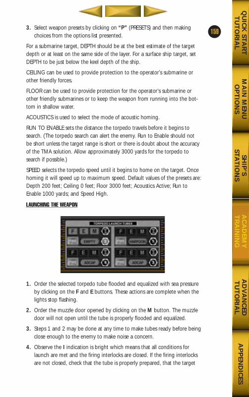
3. Select weapon presets by clicking on “P” (PRESETS) and then makingchoices from the options list presented.
For a submarine target, DEPTH should be at the best estimate of the targetdepth or at least on the same side of the layer. For a surface ship target, setDEPTH to be just below the keel depth of the ship.
CEILING can be used to provide protection to the operator’s submarine orother friendly forces.
FLOOR can be used to provide protection for the operator’s submarine orother friendly submarines or to keep the weapon from running into the bot-tom in shallow water.
ACOUSTICS is used to select the mode of acoustic homing.
RUN TO ENABLE sets the distance the torpedo travels before it begins tosearch. (The torpedo search can alert the enemy. Run to Enable should notbe short unless the target range is short or there is doubt about the accuracyof the TMA solution. Allow approximately 3000 yards for the torpedo tosearch if possible.)
SPEED selects the torpedo speed until it begins to home on the target. Oncehoming it will speed up to maximum speed. Default values of the presets are:Depth 200 feet; Ceiling 0 feet; Floor 3000 feet; Acoustics Active; Run toEnable 1000 yards; and Speed High.
LAUNCHING THE WEAPON
1. Order the selected torpedo tube flooded and equalized with sea pressureby clicking on the F and E buttons. These actions are complete when thelights stop flashing.
2. Order the muzzle door opened by clicking on the M button. The muzzledoor will not open until the tube is properly flooded and equalized.
3. Steps 1 and 2 may be done at any time to make tubes ready before beingclose enough to the enemy to make noise a concern.
4. Observe the I indication is bright which means that all conditions forlaunch are met and the firing interlocks are closed. If the firing interlocksare not closed, check that the tube is properly prepared, that the target
159
MA
IN M
ENU
OP
TIO
NS
AD
VA
NC
EDT
UT
OR
IAL
AP
PEN
DIC
ESQ
UIC
K STA
RT
TU
TO
RIA
LSH
IP’S
STAT
ION
SA
CA
DEM
YT
RA
ININ
G
688(i)/AttackSubChptr4 5/6/98 11:16 AM Page 59
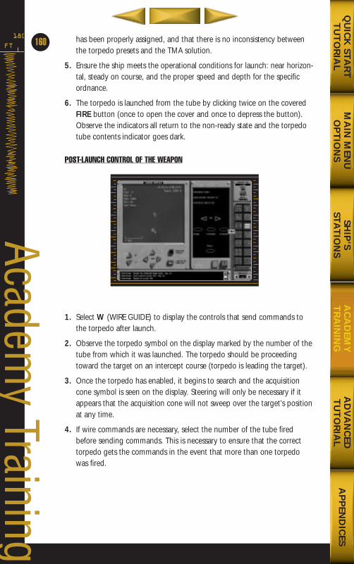
has been properly assigned, and that there is no inconsistency betweenthe torpedo presets and the TMA solution.
5. Ensure the ship meets the operational conditions for launch: near horizon-tal, steady on course, and the proper speed and depth for the specificordnance.
6. The torpedo is launched from the tube by clicking twice on the coveredFIRE button (once to open the cover and once to depress the button).Observe the indicators all return to the non-ready state and the torpedotube contents indicator goes dark.
POST-LAUNCH CONTROL OF THE WEAPON
1. Select W (WIRE GUIDE) to display the controls that send commands tothe torpedo after launch.
2. Observe the torpedo symbol on the display marked by the number of thetube from which it was launched. The torpedo should be proceedingtoward the target on an intercept course (torpedo is leading the target).
3. Once the torpedo has enabled, it begins to search and the acquisitioncone symbol is seen on the display. Steering will only be necessary if itappears that the acquisition cone will not sweep over the target’s positionat any time.
4. If wire commands are necessary, select the number of the tube firedbefore sending commands. This is necessary to ensure that the correcttorpedo gets the commands in the event that more than one torpedowas fired.
FT
180
160
Academy Training
MA
IN M
ENU
OP
TIO
NS
AD
VA
NC
EDT
UT
OR
IAL
AP
PEN
DIC
ESQ
UIC
K STA
RT
TU
TO
RIA
LSH
IP’S
STAT
ION
SA
CA
DEM
YT
RA
ININ
G
688(i)/AttackSubChptr4 5/6/98 11:16 AM Page 60
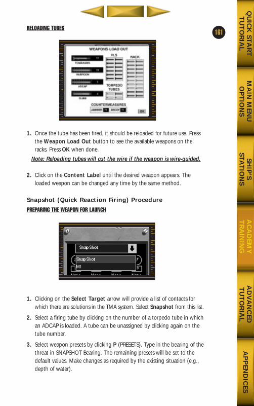
RELOADING TUBES
1. Once the tube has been fired, it should be reloaded for future use. Pressthe Weapon Load Out button to see the available weapons on theracks. Press OK when done.
Note: Reloading tubes will cut the wire if the weapon is wire-guided.
2. Click on the Content Label until the desired weapon appears. Theloaded weapon can be changed any time by the same method.
Snapshot (Quick Reaction Firing) Procedure
PREPARING THE WEAPON FOR LAUNCH
1. Clicking on the Select Target arrow will provide a list of contacts forwhich there are solutions in the TMA system. Select Snapshot from this list.
2. Select a firing tube by clicking on the number of a torpedo tube in whichan ADCAP is loaded. A tube can be unassigned by clicking again on thetube number.
3. Select weapon presets by clicking P (PRESETS). Type in the bearing of thethreat in SNAPSHOT Bearing. The remaining presets will be set to thedefault values. Make changes as required by the existing situation (e.g.,depth of water).
161
MA
IN M
ENU
OP
TIO
NS
AD
VA
NC
EDT
UT
OR
IAL
AP
PEN
DIC
ESQ
UIC
K STA
RT
TU
TO
RIA
LSH
IP’S
STAT
ION
SA
CA
DEM
YT
RA
ININ
G
688(i)/AttackSubChptr4 5/6/98 11:16 AM Page 61
LAUNCHING THE WEAPON
1. Order the selected torpedo tube flooded and equalized with sea pressureby clicking on the F and E buttons. These actions are complete when thelights stop flashing.
2. Order the muzzle door opened by clicking on M. The muzzle door willnot open until the tube is properly flooded and equalized.
3. Steps 1 and 2 may be done at any time to make tubes ready before beingclose enough to the enemy to make noise a concern.
4. Observe the I indication is bright: this means all conditions for launch aremet and the firing interlocks are closed. If the firing interlocks are notclosed, check that the tube is properly prepared, that the target has beenproperly assigned, and that there is no inconsistency between the torpe-do presets and the TMA solution.
5. Ensure the ship meets the operational conditions for launch: near horizon-tal, steady on course, and the proper speed and depth for the specificordnance.
6 The torpedo is launched from the tube by clicking twice on the coveredFire button (once to open the cover and once to depress the button).Observe the indicators all return to the non-ready state and the torpedotube contents indicator goes dark.
Launching HarpoonsThe HARPOON missile is an anti-ship cruise missile that can be launchedfrom the horizontal torpedo tubes of a submarine. It is an active radar hom-ing missile with a range of over 50 nautical miles and a sub-sonic cruisespeed. It carries a warhead of 500 lbs. of high explosive. Prior to launch, theencapsulated missile is loaded into the torpedo tube and the A-cable is con-nected to provide fire control system inputs to the missile. Electrical checksare completed and the tube is flooded and equalized with sea pressure. Theouter muzzle door is opened to make the launch tube fully ready. Thisprocess should be completed well before the anticipated time of launch.
The TMA solution for the missile need only be accurate enough to allow thesubmarine to place the missile such that the seeker search pattern willinclude the position of the target. It is also necessary to know where othersurface contacts are so that the area searched by the missile will not uninten-tionally include neutral or friendly ships.
While the Fire Control Coordinator is refining the solutions for all contacts,the Weapons Control Coordinator adjusts the seeker search pattern and themissile course so that only the primary target will be swept by the seeker ofthe missile. The Approach Officer must be satisfied that the contact solutionsare known with a high degree of certainty and that the prelaunch ordersbeing sent to the HARPOON will result in the highest probability that themissile will acquire the target and only the target.
FT
180
162
Academy Training
MA
IN M
ENU
OP
TIO
NS
AD
VA
NC
EDT
UT
OR
IAL
AP
PEN
DIC
ESQ
UIC
K STA
RT
TU
TO
RIA
LSH
IP’S
STAT
ION
SA
CA
DEM
YT
RA
ININ
G
688(i)/AttackSubChptr4 5/6/98 11:16 AM Page 62
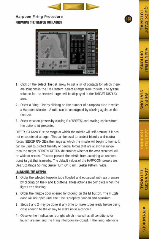
Harpoon Firing Procedure
PREPARING THE WEAPON FOR LAUNCH
1. Click on the Select Target arrow to get a list of contacts for which thereare solutions in the TMA system. Select a target from this list. The systemsolution for the selected target will be displayed in the TARGET DISPLAYarea.
2. Select a firing tube by clicking on the number of a torpedo tube in whicha Harpoon is loaded. A tube can be unassigned by clicking again on thenumber.
3. Select weapon presets by clicking P (PRESETS) and making choices fromthe options list presented.
DESTRUCT RANGE is the range at which the missile will self-destruct if it hasnot encountered a target. This can be used to protect friendly and neutralforces. SEEKER RANGE is the range at which the missile will begin to home. Itcan be used to protect friendly or neutral forces that are at shorter rangethan the target. SEEKER PATTERN determines whether the area searched willbe wide or narrow. This can prevent the missile from acquiring an uninten-tional target that is nearby. The default values of the HARPOON presets are:Destruct Range 50 nm; Seeker Turn On 0 nm; Seeker Pattern: Wide.
LAUNCHING THE WEAPON
1. Order the selected torpedo tube flooded and equalized with sea pressureby clicking on the F and E buttons. These actions are complete when thelights stop flashing.
2. Order the muzzle door opened by clicking on the M button. The muzzledoor will not open until the tube is properly flooded and equalized.
3. Steps 1 and 2 may be done at any time to make tubes ready before beingclose enough to the enemy to make noise a concern.
4. Observe the I indication is bright which means that all conditions forlaunch are met and the firing interlocks are closed. If the firing interlocks
163
MA
IN M
ENU
OP
TIO
NS
AD
VA
NC
EDT
UT
OR
IAL
AP
PEN
DIC
ESQ
UIC
K STA
RT
TU
TO
RIA
LSH
IP’S
STAT
ION
SA
CA
DEM
YT
RA
ININ
G
688(i)/AttackSubChptr4 5/6/98 11:16 AM Page 63
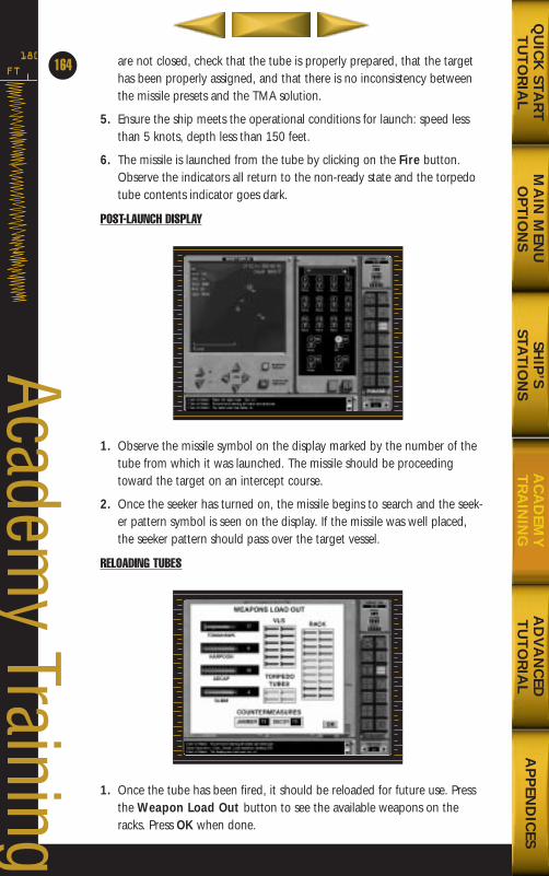
are not closed, check that the tube is properly prepared, that the targethas been properly assigned, and that there is no inconsistency betweenthe missile presets and the TMA solution.
5. Ensure the ship meets the operational conditions for launch: speed lessthan 5 knots, depth less than 150 feet.
6. The missile is launched from the tube by clicking on the Fire button.Observe the indicators all return to the non-ready state and the torpedotube contents indicator goes dark.
POST-LAUNCH DISPLAY
1. Observe the missile symbol on the display marked by the number of thetube from which it was launched. The missile should be proceedingtoward the target on an intercept course.
2. Once the seeker has turned on, the missile begins to search and the seek-er pattern symbol is seen on the display. If the missile was well placed,the seeker pattern should pass over the target vessel.
RELOADING TUBES
1. Once the tube has been fired, it should be reloaded for future use. Pressthe Weapon Load Out button to see the available weapons on theracks. Press OK when done.
FT
180
164
Academy Training
MA
IN M
ENU
OP
TIO
NS
AD
VA
NC
EDT
UT
OR
IAL
AP
PEN
DIC
ESQ
UIC
K STA
RT
TU
TO
RIA
LSH
IP’S
STAT
ION
SA
CA
DEM
YT
RA
ININ
G
688(i)/AttackSubChptr4 5/6/98 11:16 AM Page 64
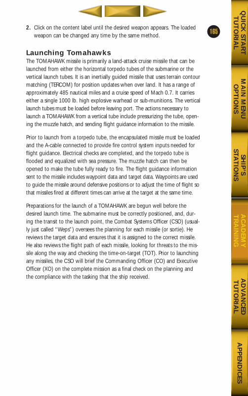
2. Click on the content label until the desired weapon appears. The loadedweapon can be changed any time by the same method.
Launching TomahawksThe TOMAHAWK missile is primarily a land-attack cruise missile that can belaunched from either the horizontal torpedo tubes of the submarine or thevertical launch tubes. It is an inertially guided missile that uses terrain contourmatching (TERCOM) for position updates when over land. It has a range ofapproximately 485 nautical miles and a cruise speed of Mach 0.7. It carrieseither a single 1000 lb. high explosive warhead or sub-munitions. The verticallaunch tubes must be loaded before leaving port. The actions necessary tolaunch a TOMAHAWK from a vertical tube include pressurizing the tube, open-ing the muzzle hatch, and sending flight guidance information to the missile.
Prior to launch from a torpedo tube, the encapsulated missile must be loadedand the A-cable connected to provide fire control system inputs needed forflight guidance. Electrical checks are completed, and the torpedo tube isflooded and equalized with sea pressure. The muzzle hatch can then beopened to make the tube fully ready to fire. The flight guidance informationsent to the missile includes waypoint data and target data. Waypoints are usedto guide the missile around defensive positions or to adjust the time of flight sothat missiles fired at different times can arrive at the target at the same time.
Preparations for the launch of a TOMAHAWK are begun well before thedesired launch time. The submarine must be correctly positioned, and, dur-ing the transit to the launch point, the Combat Systems Officer (CSO) (usual-ly just called “Weps”) oversees the planning for each missile (or sortie). Hereviews the target data and ensures that it is assigned to the correct missile.He also reviews the flight path of each missile, looking for threats to the mis-sile along the way and checking the time-on-target (TOT). Prior to launchingany missiles, the CSO will brief the Commanding Officer (CO) and ExecutiveOfficer (XO) on the complete mission as a final check on the planning andthe compliance with the tasking that the ship received.
165
MA
IN M
ENU
OP
TIO
NS
AD
VA
NC
EDT
UT
OR
IAL
AP
PEN
DIC
ESQ
UIC
K STA
RT
TU
TO
RIA
LSH
IP’S
STAT
ION
SA
CA
DEM
YT
RA
ININ
G
688(i)/AttackSubChptr4 5/6/98 11:16 AM Page 65
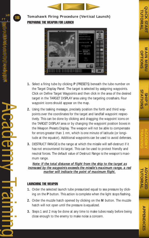
Tomahawk Firing Procedure (Vertical Launch)
PREPARING THE WEAPON FOR LAUNCH
1. Select a firing tube by clicking P (PRESETS) beneath the tube number onthe Target Display Panel. The target is selected by assigning waypoints.Click on Define Target Waypoints and then click in the area of the desiredtarget in the TARGET DISPLAY area using the targeting crosshairs. Fourwaypoint icons should appear on the map.
2. Using the tasking message, precisely position the forth and third way-points over the coordinates for the target and landfall waypoint respec-tively. This can be done by clicking and dragging the waypoint icons onthe TARGET DISPLAY area or by changing the waypoint position boxes inthe Weapon Presets Display. The weapon will not be able to compensatefor errors greater than 1 nm, which is one minute of latitude (or longi-tude at the equator). Additional waypoints can be used to avoid defenses.
3. DESTRUCT RANGE is the range at which the missile will self-destruct if ithas not encountered its target. This can be used to protect friendly andneutral forces. The default value of Destruct Range is the weapon’s maxi-mum range.
Note: If the total distance of flight from the ship to the target asincreased by the waypoints exceeds the missile’s maximum range, a red
marker will indicate the point of maximum flight.
LAUNCHING THE WEAPON
1. Order the selected launch tube pressurized equal to sea pressure by click-ing on the P button. This action is complete when the light stops flashing.
2. Order the muzzle hatch opened by clicking on the M button. The muzzlehatch will not open until the pressure is equalized.
3. Steps 1 and 2 may be done at any time to make tubes ready before beingclose enough to the enemy to make noise a concern.
FT
180
166
Academy Training
MA
IN M
ENU
OP
TIO
NS
AD
VA
NC
EDT
UT
OR
IAL
AP
PEN
DIC
ESQ
UIC
K STA
RT
TU
TO
RIA
LSH
IP’S
STAT
ION
SA
CA
DEM
YT
RA
ININ
G
688(i)/AttackSubChptr4 5/6/98 11:16 AM Page 66
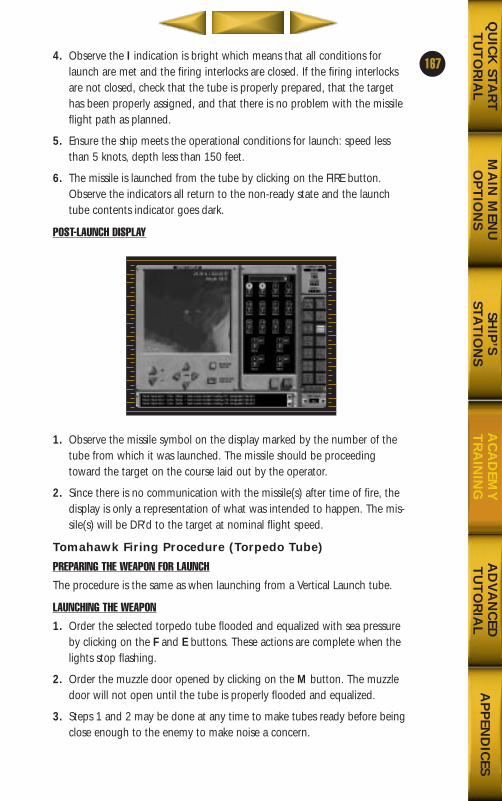
4. Observe the I indication is bright which means that all conditions forlaunch are met and the firing interlocks are closed. If the firing interlocksare not closed, check that the tube is properly prepared, that the targethas been properly assigned, and that there is no problem with the missileflight path as planned.
5. Ensure the ship meets the operational conditions for launch: speed lessthan 5 knots, depth less than 150 feet.
6. The missile is launched from the tube by clicking on the FIRE button.Observe the indicators all return to the non-ready state and the launchtube contents indicator goes dark.
POST-LAUNCH DISPLAY
1. Observe the missile symbol on the display marked by the number of thetube from which it was launched. The missile should be proceedingtoward the target on the course laid out by the operator.
2. Since there is no communication with the missile(s) after time of fire, thedisplay is only a representation of what was intended to happen. The mis-sile(s) will be DR’d to the target at nominal flight speed.
Tomahawk Firing Procedure (Torpedo Tube)
PREPARING THE WEAPON FOR LAUNCH
The procedure is the same as when launching from a Vertical Launch tube.
LAUNCHING THE WEAPON
1. Order the selected torpedo tube flooded and equalized with sea pressureby clicking on the F and E buttons. These actions are complete when thelights stop flashing.
2. Order the muzzle door opened by clicking on the M button. The muzzledoor will not open until the tube is properly flooded and equalized.
3. Steps 1 and 2 may be done at any time to make tubes ready before beingclose enough to the enemy to make noise a concern.
167
MA
IN M
ENU
OP
TIO
NS
AD
VA
NC
EDT
UT
OR
IAL
AP
PEN
DIC
ESQ
UIC
K STA
RT
TU
TO
RIA
LSH
IP’S
STAT
ION
SA
CA
DEM
YT
RA
ININ
G
688(i)/AttackSubChptr4 5/6/98 11:16 AM Page 67
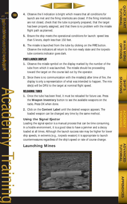
4. Observe the I indication is bright which means that all conditions forlaunch are met and the firing interlocks are closed. If the firing interlocksare not closed, check that the tube is properly prepared, that the targethas been properly assigned, and that there is no problem with the missileflight path as planned.
5. Ensure the ship meets the operational conditions for launch: speed lessthan 5 knots, depth less than 150 feet.
6. The missile is launched from the tube by clicking on the FIRE button.Observe the indicators all return to the non-ready state and the torpedotube contents indicator goes dark.
POST-LAUNCH DISPLAY
1. Observe the missile symbol on the display marked by the number of thetube from which it was launched. The missile should be proceedingtoward the target on the course laid out by the operator.
2. Since there is no communication with the missile(s) after time of fire, thedisplay is only a representation of what was intended to happen. The mis-sile(s) will be DR’d to the target at nominal flight speed.
RELOADING TUBES
1. Once the tube has been fired, it must be reloaded for future use. Pressthe Weapon Inventory button to see the available weapons on theracks. Press OK when done.
2. Click on the Content Label until the desired weapon appears. Theloaded weapon can be changed any time by the same method.
Using the Signal EjectorLoading the signal ejector is a manual process that can be time consuming.In a hostile environment, it is a good idea to have a jammer and a decoyloaded at all times. Although the launch success rate may be higher for lowership speeds, in extremis (e.g., torpedo evasion) it is appropriate to launchcountermeasures regardless of the ship’s speed or rate of course change.
Launching Mines
FT
180
168
Academy Training
MA
IN M
ENU
OP
TIO
NS
AD
VA
NC
EDT
UT
OR
IAL
AP
PEN
DIC
ESQ
UIC
K STA
RT
TU
TO
RIA
LSH
IP’S
STAT
ION
SA
CA
DEM
YT
RA
ININ
G
688(i)/AttackSubChptr4 5/6/98 11:16 AM Page 68
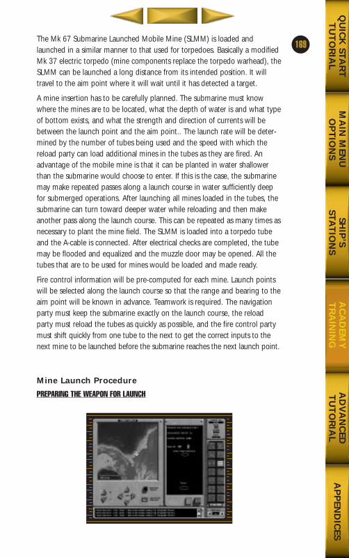
The Mk 67 Submarine Launched Mobile Mine (SLMM) is loaded andlaunched in a similar manner to that used for torpedoes. Basically a modifiedMk 37 electric torpedo (mine components replace the torpedo warhead), theSLMM can be launched a long distance from its intended position. It willtravel to the aim point where it will wait until it has detected a target.
A mine insertion has to be carefully planned. The submarine must knowwhere the mines are to be located, what the depth of water is and what typeof bottom exists, and what the strength and direction of currents will bebetween the launch point and the aim point.. The launch rate will be deter-mined by the number of tubes being used and the speed with which thereload party can load additional mines in the tubes as they are fired. Anadvantage of the mobile mine is that it can be planted in water shallowerthan the submarine would choose to enter. If this is the case, the submarinemay make repeated passes along a launch course in water sufficiently deepfor submerged operations. After launching all mines loaded in the tubes, thesubmarine can turn toward deeper water while reloading and then makeanother pass along the launch course. This can be repeated as many times asnecessary to plant the mine field. The SLMM is loaded into a torpedo tubeand the A-cable is connected. After electrical checks are completed, the tubemay be flooded and equalized and the muzzle door may be opened. All thetubes that are to be used for mines would be loaded and made ready.
Fire control information will be pre-computed for each mine. Launch pointswill be selected along the launch course so that the range and bearing to theaim point will be known in advance. Teamwork is required. The navigationparty must keep the submarine exactly on the launch course, the reloadparty must reload the tubes as quickly as possible, and the fire control partymust shift quickly from one tube to the next to get the correct inputs to thenext mine to be launched before the submarine reaches the next launch point.
Mine Launch Procedure
PREPARING THE WEAPON FOR LAUNCH
169
MA
IN M
ENU
OP
TIO
NS
AD
VA
NC
EDT
UT
OR
IAL
AP
PEN
DIC
ESQ
UIC
K STA
RT
TU
TO
RIA
LSH
IP’S
STAT
ION
SA
CA
DEM
YT
RA
ININ
G
688(i)/AttackSubChptr4 5/6/98 11:16 AM Page 69
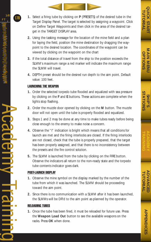
1. Select a firing tube by clicking on P (PRESETS) of the desired tube in theTarget Display Panel. The target is selected by assigning a waypoint. Clickon Define Target Waypoints and then click in the area of the desired tar-get in the TARGET DISPLAY area.
2. Using the tasking message for the location of the mine field and a planfor laying the field, position the mine destination by dragging the way-point to the desired location. The coordinates of the waypoint can beviewed by clicking on the waypoint on the chart
3. If the total distance of travel from the ship to the position exceeds theSLMM’s maximum range a red marker will indicate the maximum rangethe SLMM will travel.
4. DEPTH preset should be the desired run depth to the aim point. Defaultvalue: 100 feet.
LAUNCHING THE WEAPON
1. Order the selected torpedo tube flooded and equalized with sea pressureby clicking on the F and E buttons. These actions are complete when thelights stop flashing.
2. Order the muzzle door opened by clicking on the M button. The muzzledoor will not open until the tube is properly flooded and equalized.
3. Steps 1 and 2 may be done at any time to make tubes ready before beingclose enough to the enemy to make noise a concern.
4. Observe the “I” indication is bright which means that all conditions forlaunch are met and the firing interlocks are closed. If the firing interlocksare not closed, check that the tube is properly prepared, that the targethas been properly assigned, and that there is no inconsistency betweenthe presets and the fire control solution.
5. The SLMM is launched from the tube by clicking on the FIRE button.Observe the indicators all return to the non-ready state and the torpedotube contents indicator goes dark.
POST-LAUNCH DISPLAY
1. Observe the mine symbol on the display marked by the number of thetube from which it was launched. The SLMM should be proceedingtoward the aim point.
2. Since there is no communication with a SLMM after it has been launched,the SLMMs will be DR’d to the aim point as planned by the operator.
RELOADING TUBES
1. Once the tube has been fired, it must be reloaded for future use. Pressthe Weapon Load Out button to see the available weapons on theracks. Press OK when done.
FT
180
170
Academy Training
MA
IN M
ENU
OP
TIO
NS
AD
VA
NC
EDT
UT
OR
IAL
AP
PEN
DIC
ESQ
UIC
K STA
RT
TU
TO
RIA
LSH
IP’S
STAT
ION
SA
CA
DEM
YT
RA
ININ
G
688(i)/AttackSubChptr4 5/6/98 11:16 AM Page 70
2. Left-lick on the Content Label until the desired weapon appears. Theloaded weapon can be changed any time by the same method.
Evasive ManeuversThe best defense is never to be caught. However, when something goeswrong—an enemy has detected your submarine and launched weaponsagainst you—evasive maneuvers are required.
Torpedo EvasionNo submarine can outrun a modern anti-submarine torpedo. Survival of atorpedo attack will depend on whether or not the torpedo is able to detectthe submarine and begin to home on it. The submarine will be successful if itcan manage to remain undetected by the torpedo or can confuse the torpe-do homing logic.
If the torpedo is well placed (the enemy had a good fire control solution onyour submarine prior to launching the torpedo), early detection is essential.The sonar operators must be able to recognize a torpedo even before itbegins active homing. As soon as the torpedo is reported, the submarinemust maneuver so that the firing solution of the enemy is no longer valid,and the torpedo will not pass close enough to your submarine to be able todetect it. The submarine maneuver should include a course change to getaway from the projected track of the torpedo, an increase in speed (probablyto maximum), and possibly a depth change. Depending on the local condi-tions, it may be possible to put the submarine on the opposite side of a ther-mal layer from the torpedo (you have to know the water depth and thesound-speed profile (SSP)) by going shallow or deep. If the water is shallow,being near the bottom may help by giving the torpedo false target returnsfrom the bottom.
Evasion plans may also include the use of countermeasures. Countermeasurescan be of two types: decoys and jammers. Decoys give false returns to thetorpedo that is homing and will cause the torpedo to home on the decoyinstead of the submarine. Jammers produce very loud noise over a broadspectrum and make it difficult for the torpedo or the platform that launchedit detect the submarine by acoustic means. Whenever the submarine is in apotentially hostile situation, the Commanding Officer should know inadvance what they will do to evade torpedoes. His plan must take into con-sideration all factors in the local environment.
171
MA
IN M
ENU
OP
TIO
NS
AD
VA
NC
EDT
UT
OR
IAL
AP
PEN
DIC
ESQ
UIC
K STA
RT
TU
TO
RIA
LSH
IP’S
STAT
ION
SA
CA
DEM
YT
RA
ININ
G
688(i)/AttackSubChptr4 5/6/98 11:16 AM Page 71
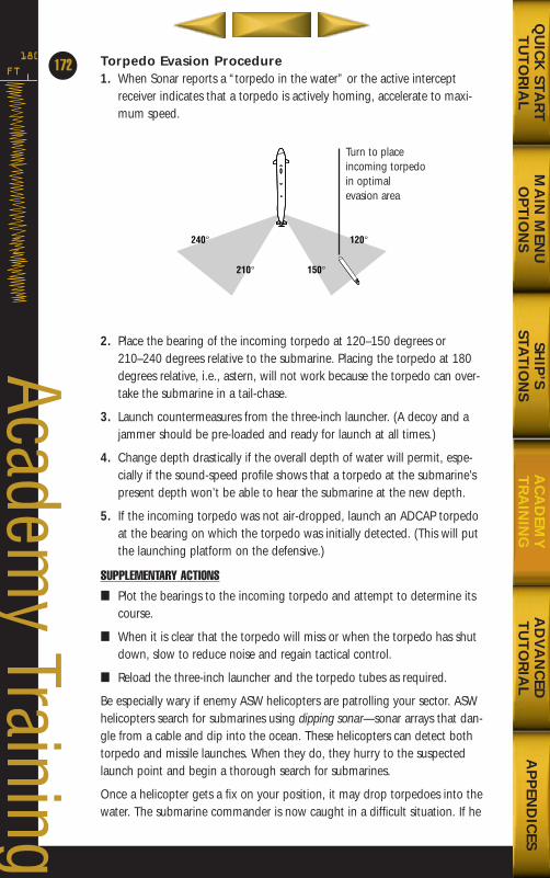
Torpedo Evasion Procedure1. When Sonar reports a “torpedo in the water” or the active intercept
receiver indicates that a torpedo is actively homing, accelerate to maxi-mum speed.
2. Place the bearing of the incoming torpedo at 120–150 degrees or210–240 degrees relative to the submarine. Placing the torpedo at 180degrees relative, i.e., astern, will not work because the torpedo can over-take the submarine in a tail-chase.
3. Launch countermeasures from the three-inch launcher. (A decoy and ajammer should be pre-loaded and ready for launch at all times.)
4. Change depth drastically if the overall depth of water will permit, espe-cially if the sound-speed profile shows that a torpedo at the submarine’spresent depth won’t be able to hear the submarine at the new depth.
5. If the incoming torpedo was not air-dropped, launch an ADCAP torpedoat the bearing on which the torpedo was initially detected. (This will putthe launching platform on the defensive.)
SUPPLEMENTARY ACTIONS
■ Plot the bearings to the incoming torpedo and attempt to determine itscourse.
■ When it is clear that the torpedo will miss or when the torpedo has shutdown, slow to reduce noise and regain tactical control.
■ Reload the three-inch launcher and the torpedo tubes as required.
Be especially wary if enemy ASW helicopters are patrolling your sector. ASWhelicopters search for submarines using dipping sonar—sonar arrays that dan-gle from a cable and dip into the ocean. These helicopters can detect bothtorpedo and missile launches. When they do, they hurry to the suspectedlaunch point and begin a thorough search for submarines.
Once a helicopter gets a fix on your position, it may drop torpedoes into thewater. The submarine commander is now caught in a difficult situation. If he
FT
180
172
Academy Training
MA
IN M
ENU
OP
TIO
NS
AD
VA
NC
EDT
UT
OR
IAL
AP
PEN
DIC
ESQ
UIC
K STA
RT
TU
TO
RIA
LSH
IP’S
STAT
ION
SA
CA
DEM
YT
RA
ININ
G
210¡ 150¡
240¡ 120¡
Turn to placeincoming torpedoin optimal evasion area
688(i)/AttackSubChptr4 5/6/98 11:16 AM Page 72
increases speed to outrun the torpedoes, the helicopters can track him moreeasily and will dump more torpedoes. If the commander decides to keep hisspeed down and attempt to outmaneuver the torpedoes, he runs the risk oftaking a hit. Neither scenario is good, and both can be avoided by keeping alow profile when making attack runs.
Special Forces OperationsNaval Special Warfare (NSW) may involve the insertion of special operationsforces (SOF) into a hostile territory. SOF include such units as Army Rangers,Marine Reconnaissance (Force Recon) units, or Navy Sea-Air-Land (SEAL)units. The SEALs have the most experience working from submarines and arecapable of submerged launch and recovery. Other units can be deployedfrom a submarine, but that would require surfaced launch and recovery. Asubmerged launch or recovery of SEALs requires the submarine to hover at ashallow depth. There must be a minimum of water flow over the deck so thatthe swimmers don’t have to work against a strong current while they handleequipment. Being shallow means that it will be easier and faster to get theswimmers in and out of the submarine.
Los Angeles class submarines use the escape trunk to lock out two swimmersat a time with whatever equipment they can also fit into the cramped cham-ber. Larger equipment and substances that are not brought into the subma-rine atmosphere (such as gasoline for the outboard motors) must be storedexternal to the pressure hull. To lock out, the divers enter the escape trunkand flood it to a pre-determined level. The remaining volume is pressurizedwith air to a pressure equal to sea pressure. When the pressure is greatenough, the hatch can be opened. The divers then leave the pressurized airbubble and exit the hatch, using self-contained underwater breathing appa-ratus (SCUBA). Once outside the submarine, the SEALs begin to rig theirequipment while others are locking out. The equipment may include combatrubber raiding craft (CRRC) with outboard motors if there is a long distanceto go. When the entire team has locked out, the SEALs depart and the sub-marine can either loiter on station or go to another area to await the recov-ery operation.
To recover the SEALs, the submarine would most likely be at a pre-deter-mined location at a specified time. Waiting at periscope depth, the subma-rine will search for the SEALs visually and with passive sonar while listeningon designated radio circuits. Once the rendezvous is made, the submarineagain hovers for the recovery. The SEALs will stow some of their equipmenttopside and take the rest below decks as they lock in. To effect a surfacedlaunch or recovery of SOF personnel, the submarine should surface as quicklyas possible and have personnel standing by to help with the movement ofequipment to the hatch and then topside. The sooner the evolution can becompleted and the submarine can re-submerge, the less the chance of detec-tion and attack by enemy forces.
173
MA
IN M
ENU
OP
TIO
NS
AD
VA
NC
EDT
UT
OR
IAL
AP
PEN
DIC
ESQ
UIC
K STA
RT
TU
TO
RIA
LSH
IP’S
STAT
ION
SA
CA
DEM
YT
RA
ININ
G
688(i)/AttackSubChptr4 5/6/98 11:16 AM Page 73
Submerged Lock out ProcedureNote: The following procedure is for information purposes, indicating in
part the complexity of the operation. The actual procedural require-ments are listed in the section, Launching Special Operations Forces,
below.
Initial Conditions• The submarine has arrived at the mission launch point and has conducted
surveillance in order to ascertain that there is no immediate threat to theSEALs.
• Depending on the sea state, the submarine is shallow or at periscopedepth with no more than approximately 1 knot of water flow across thedeck. The submarine may be hovering instead of trying to control depthwith the normal control surfaces.
• SEAL teams have been briefed and are fully ready to commence the mission.
• All necessary personnel are on station.
ActionsThe Officer of the Deck must give permission to conduct each step of the proce-dure. The Commanding Officer must authorize any change in the rig for dive.
1. Open the drain valve to check the escape trunk dry. Shut the drain valve.
2. Open the lower hatch. Trunk operator and two SEALs with necessaryequipment enter the trunk and secure the hatch.
3. Flood the trunk to the bubble line.
4. Undog (open) the upper hatch. (It will not open yet due to sea pressure.)
5. Pressurize the escape trunk using high-pressure air until the pressure isequal to that of the surrounding sea water.
6. Push open the upper hatch. SEALs depart the trunk one at a time.
7. Shut and dog the upper hatch.
8. Open the vent valve and then open the drain valve to drain the waterfrom the trunk. Shut the drain valve.
9. Repeat steps 2 through 8, as required, to lock out the SEAL team(s).
10. When the lock out evolution is complete, rig the escape trunk for dive.
Submerged Lock in ProcedureInitial Conditions• The submarine has arrived at the designated recovery point and made
contact with the SEAL teams returning from their mission.
• Depending on the sea state, the submarine is shallow or at periscopedepth with no more than approximately 1 knot of water flow across thedeck. The submarine may be hovering instead of trying to control depthwith the normal control surfaces.
• All necessary personnel are on station.
FT
180
174
Academy Training
MA
IN M
ENU
OP
TIO
NS
AD
VA
NC
EDT
UT
OR
IAL
AP
PEN
DIC
ESQ
UIC
K STA
RT
TU
TO
RIA
LSH
IP’S
STAT
ION
SA
CA
DEM
YT
RA
ININ
G
688(i)/AttackSubChptr4 5/6/98 11:16 AM Page 74
ActionsThe Officer of the Deck must give permission to conduct each step of theprocedure. The Commanding Officer must authorize any change in the rigfor dive.
1. Open the drain valve to check the escape trunk dry. Shut the drain valve.
2. Flood the trunk to the bubble line.
3. Undog (open) the upper hatch. (It will not open yet due to sea pressure.)
4. Pressurize the escape trunk using high pressure air until the pressure isequal to that of the surrounding sea water.
5. Push open the upper hatch. Two returning SEALs can enter the trunk, oneat a time.
6. Shut and dog the upper hatch.
7. Open the vent valve and then open the drain valve to drain the waterfrom the trunk. Shut the drain valve.
8. Open the lower hatch to allow the SEALs to re-enter the submarine.
9. Repeat steps 2 through 8, as required, to lock in the SEAL team(s).
10. When the lock in evolution is complete, rig the escape trunk for dive.
Surfaced Launch ProcedureInitial Conditions• The submarine has arrived at the mission launch point and has conducted
surveillance in order to ascertain that there is no immediate threat to theSOF that will disembark. The submarine is at periscope depth.
• The SOF have all been briefed and are fully ready to begin the mission.
• All necessary personnel are on station.
ActionsThe Officer of the Deck must give permission to conduct each step of theprocedure. The Commanding Officer must authorize any change in the rigfor dive.
1. Surface the ship with a short (5 second) emergency main ballast tank blow.
2. Immediately start an air charge to replenish the high-pressure air banks.
3. Run the low-pressure blower on the main ballast tanks if the additionalnoise will not result in a significant increase in the probability of detectionby threat forces.
4. Man the bridge with the minimum amount of equipment for the Officerof the Deck.
5. Drain and open the weapons shipping (forward) hatch and/or the escapetrunk (midships) hatch. Move SOF personnel and equipment topsideexpeditiously.
6. If the situation warrants it, station personnel on the bridge and on deckwith weapons to provide self-defense capability against hostile forces.
7. As soon as the SOF have been launched, rig the hatches and the bridgefor dive. Secure the low-pressure blower if that was used.
175
MA
IN M
ENU
OP
TIO
NS
AD
VA
NC
EDT
UT
OR
IAL
AP
PEN
DIC
ESQ
UIC
K STA
RT
TU
TO
RIA
LSH
IP’S
STAT
ION
SA
CA
DEM
YT
RA
ININ
G
688(i)/AttackSubChptr4 5/6/98 11:16 AM Page 75
8. Verify the rig for dive and submerge the ship.
Surfaced Recovery ProcedureInitial Conditions• The submarine has arrived at the mission recovery point and has conduct-
ed surveillance in order to make contact with the SOF that will embark.
• The submarine is at periscope depth.
• The SOF have been detected. Communications were established to deter-mine the time of the rendezvous, whether there are enemy forces in thearea, and whether there are any wounded.
• All necessary personnel are on station.
ActionsThe Officer of the Deck must give permission to conduct each step of theprocedure. The Commanding Officer must authorize any change in the rigfor dive.
1. Surface the ship with a short (5 second) emergency main ballast tank blow.
2. Immediately start an air charge to replenish the high pressure air banks.
3. Run the low pressure blower on the main ballast tanks if the additionalnoise will not result in a significant increase in the probability of detectionby threat forces.
4. Man the bridge with the minimum amount of equipment for the Officerof the Deck.
5. Drain and open the weapons shipping (forward) hatch and/or the escapetrunk (midships) hatch.
6. If the situation warrants it, station personnel on the bridge and on deckwith weapons to provide self-defense capability against hostile forces.
7. Move SOF personnel and equipment below decks expeditiously. As soonas the SOF have been recovered, rig the hatches and the bridge for dive.Secure the low pressure blower if that was used.
8. Verify the rig for dive and submerge the ship.
Launching Special Operations ForcesInitial Conditions• The submarine has arrived at the mission launch point and has conducted
surveillance in order to ascertain that there is no immediate threat to theSEALs.
• The submarine is at periscope depth or shallower with no more thanapproximately 1 knot of water flow across the deck.
Actions• When all conditions for launch have been met, the XO will announce that
“All SEALs are away.”
FT
180
176
Academy Training
MA
IN M
ENU
OP
TIO
NS
AD
VA
NC
EDT
UT
OR
IAL
AP
PEN
DIC
ESQ
UIC
K STA
RT
TU
TO
RIA
LSH
IP’S
STAT
ION
SA
CA
DEM
YT
RA
ININ
G
688(i)/AttackSubChptr4 5/6/98 11:17 AM Page 76
Recovering Special Operations ForcesInitial conditions
• a. The submarine has arrived at the designated recovery point at thedesignated time.
• b. The submarine is at periscope depth or shallower with no morethan approximately 1 knot of water flow across the deck.
ActionsWhen all conditions for recovery have been met, the XO will announce that“All SEALs have been recovered.”
Search and RescueOperationsPrinciples of the Operating ProcedureSearch and rescue (SAR) operations are conducted by submarines in varioussituations. Since one of the most important factors in SAR is to conduct theoperation in the quickest manner possible, a submarine may be tasked toconduct the operation if it is the closest to the point of rescue. If the rescue isto be conducted in a hostile area, the submarine’s stealth makes it a goodchoice for the job. A problem with using the submarine for SAR is the vulner-ability of the sub while surfaced.
There are two types of SAR operations for a submarine. The first is rescuing aperson on the surface, such as a downed pilot or sailors from a ship. Thisoperation is very similar to the surfaced special forces recovery, with theexception that the person in the water is not trained in the procedure. Thesubmarine learns the best known location of the person(s), and travels to thelocation to search. The submarine is better able to search from the surface,but is much more vulnerable to enemy detection and attack. Once the per-son(s) is located, the submarine approaches the person, surfaces, and slowsto conduct the rescue. The quicker the rescue can be conducted and thesubmarine can be submerged, the safer the operation.
Submarines can also be used as the mother ship for a Deep SubmergenceRescue Vehicle (DSRV) which can be used to rescue personnel from adowned submarine. A submarine can carry the DSRV to the location of thesearch, using intelligence and the ship’s sensors to locate the downed sub.The sub then slows to near zero speed and hovers in place while the DSRVconducts the rescue. This operation may be long, depending on the numberof trips necessary to rescue all the survivors.
Surface Search and Rescue ProcedureInitial Conditions• The submarine has arrived at the best known location of the person.
• Depending on the level of hostility in the area, the ship is on the surfaceor at periscope depth.
• All necessary personnel are on station.
177
MA
IN M
ENU
OP
TIO
NS
AD
VA
NC
EDT
UT
OR
IAL
AP
PEN
DIC
ESQ
UIC
K STA
RT
TU
TO
RIA
LSH
IP’S
STAT
ION
SA
CA
DEM
YT
RA
ININ
G
688(i)/AttackSubChptr4 5/6/98 11:17 AM Page 77
Actions1. The ship uses all sensors (periscope, radar if surfaced, sonar, ESM) to
search the area for the person while maintaining safe position withrespect to threat contacts.
2. Once the person is located, the ship drives as close as possible.
3. If not already on the surface, the ship quickly surfaces the ship by con-ducting a 5 second emergency blow (raise the Emergency Blow Valvehandle; lower it after 5 seconds). Immediately commence ventilating(push Ventilate button) and start an air charge (push HP Air button) toreplenish the HP air banks.
4. When the ship has met the speed and depth requirements (slow and sur-faced), the rescue will be conducted. When complete, the XO will reportthat the person is on board.
5. Quickly submerge the ship and continue operation, keeping in mind thepossible detection of the submarine during the SAR.
DSRV OperationsInitial Conditions• The submarine is in the correct area to conduct the SAR.
• The DSRV is attached with personnel standing by for operations.
Actions1. Slow to near zero speed and hover at a safe depth.
2. DSRV operations will be conducted. The XO will report “Conn, XO. TheDSRV is away.”
3. After some time, the operation will be complete. (The submarine mayhave waited on station or may have departed and returned to the recov-ery point.) The XO will report “Conn, XO. The DSRV is mated to the hatch.”
Casualty ProceduresFlooding is one of the most feared of submarine casualties. The ability to sur-vive a flooding casualty depends on submarine design factors and the train-ing of the crew. A submarine has a certain amount of positive buoyancywhen it is on the surface. If more water is taken aboard than the maximumpositive buoyancy, then the submarine will be negatively buoyant and willsink. (If propulsion can be maintained, additional weight can be compensat-ed for with speed and an up-angle on the hull.)
The amount of water taken aboard during a flooding casualty is proportionalto the size of the hole, the depth at which the flooding occurs, and thelength of time it takes to stop the flow of water into the submarine. (Depthmatters because submergence pressure increases by 44.4 pounds per squareinch for every 100 foot depth increase. That is almost three atmospheresincrease in pressure for every 100 feet.) The time to stop the flooding can bedecreased by having emergency closure valves that operate remotely on allsea water systems of significant size. Crew training is also important to be
FT
180
178
Academy Training
MA
IN M
ENU
OP
TIO
NS
AD
VA
NC
EDT
UT
OR
IAL
AP
PEN
DIC
ESQ
UIC
K STA
RT
TU
TO
RIA
LSH
IP’S
STAT
ION
SA
CA
DEM
YT
RA
ININ
G
688(i)/AttackSubChptr4 5/6/98 11:17 AM Page 78
able to locate, isolate, and repair the source of flooding.
If flooding occurs, speed should be used to achieve an upward depth rate. Ifpropulsion power is lost because of flooding in the engine room, the residualspeed will still get the submarine moving toward the surface. The ship con-trol party should keep a moderate up-angle on the ship; a large angle couldkeep the damage control parties from being able to move in the ship, andtoo large an angle could result in the loss of air from the ballast tanks whenthe emergency main ballast tank blow system is used.
Flooding ProcedureImmediate Actions
• Flooding most likely occurs as a result of a close explosion. The persondiscovering the flooding should report, by the fastest means, the loca-tion of the flooding and the source of the water if that can be deter-mined.
• The Chief of the Watch (COW) will announce on the generalannouncing system “Flooding in the ______ (compartment or space)”,sound the Collision Alarm, and pass the word passed again.
• Flooding results in reduced propulsion, reduced ability to controlship’s depth, and an angle on the ship.
• The Officer of the Deck (OOD) should order the Diving Officer tobring the ship to a shallow depth without using a large trim angle onthe ship.
• The OOD should use enough speed to maintain the ordered depth aslong as propulsion is available.
• The OOD should emergency surface the ship if the ship was very deepat the beginning of the casualty, if propulsion is lost, or if the amountof water flooded into the ship begins to have a noticeable effect onship control. (Emergency surfacing means conducting an emergencyblow of the main ballast tanks by raising the Emergency Blow Valve.)
Supplementary Actions• The ship will recover depth control and speed over time as the crew
conducts damage control operations.
• If the ship emergency surfaced, pass the word to “Prepare to surface”and complete the normal surfacing procedure. Recharge the main airbanks following the emergency blow.
Emergency DeepPrinciples of the Casualty ProcedureThe most vulnerable time for the submarine with regard to encounteringanother vessel unexpectedly is when proceeding to periscope depth. If theOOD believes that a risk of collision exists, he will announce “EmergencyDeep” which will cause the members of the ship control party to quickly takeactions to get the submarine back to a safe depth.
179
MA
IN M
ENU
OP
TIO
NS
AD
VA
NC
EDT
UT
OR
IAL
AP
PEN
DIC
ESQ
UIC
K STA
RT
TU
TO
RIA
LSH
IP’S
STAT
ION
SA
CA
DEM
YT
RA
ININ
G
688(i)/AttackSubChptr4 5/6/98 11:17 AM Page 79
FT
180
180
Academy Training
Initial Conditions• The submarine is at or approaching periscope depth.
• The Approach Officer (CO) or the OOD is manning the periscope.
• The officer on the periscope sees a contact that is an immediate colli-sion threat.
Immediate Actions• The officer on the periscope immediately lowers the periscope.
• The OOD rings up All Ahead Full on the Engine Order Telegraph andorders a safe depth (150ft or deeper).
Supplementary Actions• The OOD slows the sub as soon as the ship is at a safe depth.
The Future Of Seapowerby Admiral Guven Erkaya Commander-in-Chief, Turkish Naval Forces
Generally speaking, weapon ranges were shorter than detec-tion and identification ranges until the 1950s. Hence, the effective-ness of naval platforms was limited by the range and capabilities ofonboard weapons and sensors. Naval strategy and tactical doctrinesreflected these limitations. However, over the last 50 years, we havewitnessed the development of guided weapons and cruise missileswith greater precision, larger warheads and ranges far beyond thoseof onboard detection and identification sensors.
These improvements made it necessary to obtain target datathrough external sensors in order to target long-range weapons effec-tively. In the meantime, continuous and real-time transfer of dataobtained through off -board sensors to weapon platforms becamenecessary.
Today, those navies possessing long-range weapons, wide areasurveillance and targeting systems and advanced datalinks maintaina significant advantage. These developments have resulted in signifi-cant changes to naval strategy and tactics, which will continue intothe next century. The accuracy, range and destructive power of mis-siles will further improve, while naval guns will benefit from thewider use of smart munitions.
The importance of constant surveillance, the collection, corre-lation and fusion of data, and the real-time dissemination ofprocessed data to individual platforms will further increase. Withoutthis real-time data transfer, the potential firepower offered by mod-ern weapons and surveillance systems will not translate into tacticaland strategic advantage. Improvements are expected in stealth tech-nology, leading to marked reductions in radar, acoustic, infrared andelectromagnetic signatures.
The role of the ballistic missile in global deterrence will con-tinue, and nuclear-powered submarines will remain the most suitableplatform. Indeed, submarines will continue to cause problems forsurface forces by virtue of their stealth. Aircraft carriers, in additionto sea control and power projection, will continue to form the back-
MA
IN M
ENU
OP
TIO
NS
AD
VA
NC
EDT
UT
OR
IAL
AP
PEN
DIC
ESQ
UIC
K STA
RT
TU
TO
RIA
LSH
IP’S
STAT
ION
SA
CA
DEM
YT
RA
ININ
G
688(i)/AttackSubChptr4 5/6/98 11:17 AM Page 80
bone of the blue-water task force. Cruisers and other large escortswill maintain their importance.
The effectiveness of cruise missiles will also increase.Launched from naval platforms at standoff ranges, these weaponswill reduce the importance of manned aircraft as strike assets. Assuch, naval forces will be able to control larger sea areas, whilst atthe same time being capable of neutralising point targets locateddeep inland.
The economic use of the seas and the sea bed has increasedover the last half century. While national sovereignty over the seaswas limited to just three miles (4.8km) in the past, the exclusive eco-nomic interest of countries has now expanded to 200 miles (322km)and even further in some cases. Given the ever greater exploitationof maritime resources, it appears likely that international conflictsmay increasingly shift to sea areas.
With the development of a new world order, the resolution ofemerging new crises requires multi-polar and multi-national arrange-ments. Before the end of the Cold War, reaching a consensus on thethreat was not difficult beyond some minor points. Today, countriesare faced with a multitude of potential threats including:
❏ ideological and cultural conflicts which have existed throughout history;
❏ rising nationalism and racism; ❏ increasing terrorism;❏ the spread of organised crime;❏ the proliferation of weapons of mass destruction;❏ expansionist foreign policies;❏ imbalances in the distribution of finite world resources
among a rising global population; and ❏ the requirement for urgent action to protect the environment.Addressing these security risks requires the combination, or at
least the harmonisation, of various policies. Foreign and defence poli-cies - once seen as separate - need to be combined. Meanwhile, eco-nomic, social and other national policies must be aligned with themain thrust of a common foreign and security policy.
From an international perspective, the protection of global secu-rity interests necessitates the need for multinational maritimeforces, and countries which participate in coalition operations willnaturally increase their stature and influence on the world stage.
Traditional tasks - such as defence against threats from the sea;protection of sea lines of communication, natural maritimeresources, and national interests overseas - will continue. Navies willalso find a greater role in low intensity conflicts (including the sup-port of peacekeeping operations), humanitarian aid, search and res-cue, environmental protection, and cooperation with other agenciesagainst organised crime.
Navies, exploiting the additional capabilities obtained throughthe revolution in technology, and their inherent attributes of mobili-ty, flexibility and endurance, will continue to offer invaluable optionsto politicians in the maintenance and protection of the nationalinterests into the next century.
181
MA
IN M
ENU
OP
TIO
NS
AD
VA
NC
EDT
UT
OR
IAL
AP
PEN
DIC
ESQ
UIC
K STA
RT
TU
TO
RIA
LSH
IP’S
STAT
ION
SA
CA
DEM
YT
RA
ININ
G
688(i)/AttackSubChptr4 5/6/98 11:17 AM Page 81
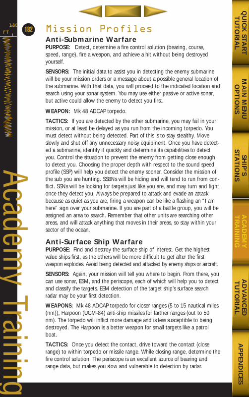
Mission ProfilesAnti-Submarine WarfarePURPOSE: Detect, determine a fire control solution (bearing, course,speed, range), fire a weapon, and achieve a hit without being destroyedyourself.
SENSORS: The initial data to assist you in detecting the enemy submarinewill be your mission orders or a message about a possible general location ofthe submarine. With that data, you will proceed to the indicated location andsearch using your sonar system. You may use either passive or active sonar,but active could allow the enemy to detect you first.
WEAPON: Mk 48 ADCAP torpedo.
TACTICS: If you are detected by the other submarine, you may fail in yourmission, or at least be delayed as you run from the incoming torpedo. Youmust detect without being detected. Part of this is to stay stealthy. Moveslowly and shut off any unnecessary noisy equipment. Once you have detect-ed a submarine, identify it quickly and determine its capabilities to detectyou. Control the situation to prevent the enemy from getting close enoughto detect you. Choosing the proper depth with respect to the sound speedprofile (SSP) will help you detect the enemy sooner. Consider the mission ofthe sub you are hunting. SSBNs will be hiding and will tend to run from con-flict. SSNs will be looking for targets just like you are, and may turn and fightonce they detect you. Always be prepared to attack and evade an attackbecause as quiet as you are, firing a weapon can be like a flashing an “I amhere” sign over your submarine. If you are part of a battle group, you will beassigned an area to search. Remember that other units are searching otherareas, and will attack anything that moves in their areas, so stay within yoursector of the ocean.
Anti-Surface Ship WarfarePURPOSE: Find and destroy the surface ship of interest. Get the highestvalue ships first, as the others will be more difficult to get after the firstweapon explodes. Avoid being detected and attacked by enemy ships or aircraft.
SENSORS: Again, your mission will tell you where to begin. From there, youcan use sonar, ESM, and the periscope, each of which will help you to detectand classify the targets. ESM detection of the target ship’s surface searchradar may be your first detection.
WEAPONS: Mk 48 ADCAP torpedo for closer ranges (5 to 15 nautical miles(nm)), Harpoon (UGM-84) anti-ship missiles for farther ranges (out to 50nm). The torpedo will inflict more damage and is less susceptible to beingdestroyed. The Harpoon is a better weapon for small targets like a patrolboat.
TACTICS: Once you detect the contact, drive toward the contact (closerange) to within torpedo or missile range. While closing range, determine thefire control solution. The periscope is an excellent source of bearing andrange data, but makes you slow and vulnerable to detection by radar.
FT
180
182
Academy Training
MA
IN M
ENU
OP
TIO
NS
AD
VA
NC
EDT
UT
OR
IAL
AP
PEN
DIC
ESQ
UIC
K STA
RT
TU
TO
RIA
LSH
IP’S
STAT
ION
SA
CA
DEM
YT
RA
ININ
G
688(i)/AttackSubChptr4 5/6/98 11:17 AM Page 82
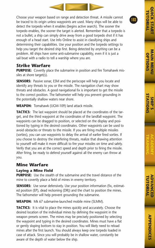
Choose your weapon based on range and detection threat. A missile cannotbe traced to its origin unless waypoints are used. Many ships will be able todetect the torpedo when it enables (begins active search). The sooner thetorpedo enables, the sooner the target is alerted. Remember that a torpedo isnot a bullet; a ship can simply drive away from a good torpedo shot if it hasenough of a head start. Use Info Online to assist in classifying ships anddetermining their capabilities. Use your position and the torpedo settings tohelp you target the desired ship first. Being detected by anything can be aproblem. All ships have some anti-submarine capability, even if it is just a sail boat with a radio to tell a warship where you are.
Strike WarfarePURPOSE: Covertly place the submarine in position and fire Tomahawk mis-siles at shore target(s).
SENSORS: Passive sonar, ESM and the periscope will help you locate andidentify any threats to you or the missile. The navigation chart may showthreats and obstacles. A good navigational fix is important to get the missileto the correct position. The fathometer will help you prevent grounding inthe potentially shallow waters near shore.
WEAPON: Tomahawk (UGM-109) land attack missile.
TACTICS: The last waypoint should be placed at the coordinates of the tar-get, and the third waypoint at the coordinates of the landfall waypoint. Thewaypoints can be dragged to position, or selected on the display and posi-tioned by typing in the desired coordinates. Other waypoints can be used toavoid obstacles or threats to the missile. If you are firing multiple missiles(sorties), you can use waypoints to delay the arrival of earlier fired sorties. Ifyou choose to destroy the interfering threats, realize that drawing attentionto yourself will make it more difficult to fire your missiles on time and safely.Verify that you are at the correct speed and depth prior to firing the missile.After firing, be ready to defend yourself against all the enemy can throw atyou.
Mine WarfareLaying a Mine FieldPURPOSE: Use the stealth of the submarine and the travel distance of themine to covertly place a field of mines in enemy territory.
SENSORS: Use sonar defensively. Use your position information (fix, estimat-ed position (EP), dead reckoning (DR)) and the chart to position the mines.The fathometer will help prevent grounding the submarine.
WEAPON: Mk 67 submarine-launched mobile mine (SLMM).
TACTICS: It is vital to place the mines quickly and accurately. Choose thedesired location of the individual mines by defining the waypoint in theweapon presets screen. The mines may be precisely positioned by selectingthe waypoint and typing in the desired coordinates. Mines must have a flator gently sloping bottom to stay in position. You will likely need to reloadmines after the first launch. You should always keep one torpedo loaded incase of attack. Since you will probably be in shallow water, constantly beaware of the depth of water below the ship.
183
MA
IN M
ENU
OP
TIO
NS
AD
VA
NC
EDT
UT
OR
IAL
AP
PEN
DIC
ESQ
UIC
K STA
RT
TU
TO
RIA
LSH
IP’S
STAT
ION
SA
CA
DEM
YT
RA
ININ
G
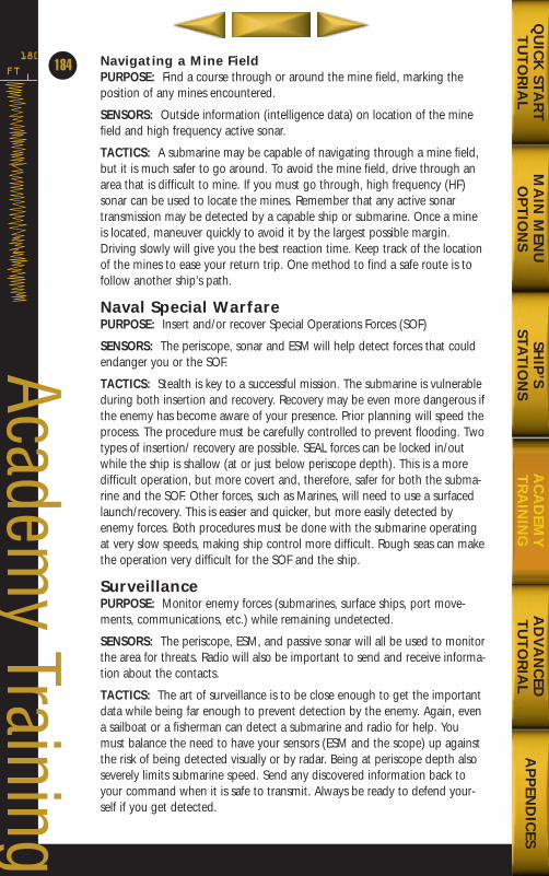
Navigating a Mine FieldPURPOSE: Find a course through or around the mine field, marking theposition of any mines encountered.
SENSORS: Outside information (intelligence data) on location of the minefield and high frequency active sonar.
TACTICS: A submarine may be capable of navigating through a mine field,but it is much safer to go around. To avoid the mine field, drive through anarea that is difficult to mine. If you must go through, high frequency (HF)sonar can be used to locate the mines. Remember that any active sonartransmission may be detected by a capable ship or submarine. Once a mineis located, maneuver quickly to avoid it by the largest possible margin.Driving slowly will give you the best reaction time. Keep track of the locationof the mines to ease your return trip. One method to find a safe route is tofollow another ship’s path.
Naval Special WarfarePURPOSE: Insert and/or recover Special Operations Forces (SOF)
SENSORS: The periscope, sonar and ESM will help detect forces that couldendanger you or the SOF.
TACTICS: Stealth is key to a successful mission. The submarine is vulnerableduring both insertion and recovery. Recovery may be even more dangerous ifthe enemy has become aware of your presence. Prior planning will speed theprocess. The procedure must be carefully controlled to prevent flooding. Twotypes of insertion/ recovery are possible. SEAL forces can be locked in/outwhile the ship is shallow (at or just below periscope depth). This is a moredifficult operation, but more covert and, therefore, safer for both the subma-rine and the SOF. Other forces, such as Marines, will need to use a surfacedlaunch/recovery. This is easier and quicker, but more easily detected byenemy forces. Both procedures must be done with the submarine operatingat very slow speeds, making ship control more difficult. Rough seas can makethe operation very difficult for the SOF and the ship.
SurveillancePURPOSE: Monitor enemy forces (submarines, surface ships, port move-ments, communications, etc.) while remaining undetected.
SENSORS: The periscope, ESM, and passive sonar will all be used to monitorthe area for threats. Radio will also be important to send and receive informa-tion about the contacts.
TACTICS: The art of surveillance is to be close enough to get the importantdata while being far enough to prevent detection by the enemy. Again, evena sailboat or a fisherman can detect a submarine and radio for help. Youmust balance the need to have your sensors (ESM and the scope) up againstthe risk of being detected visually or by radar. Being at periscope depth alsoseverely limits submarine speed. Send any discovered information back toyour command when it is safe to transmit. Always be ready to defend your-self if you get detected.
FT
180
184
Academy Training
MA
IN M
ENU
OP
TIO
NS
AD
VA
NC
EDT
UT
OR
IAL
AP
PEN
DIC
ESQ
UIC
K STA
RT
TU
TO
RIA
LSH
IP’S
STAT
ION
SA
CA
DEM
YT
RA
ININ
G
688(i)/AttackSubChptr4 5/6/98 11:17 AM Page 84
MA
IN M
ENU
OP
TIO
NS
AP
PEN
DIC
ESQ
UIC
K STA
RT
TU
TO
RIA
LSH
IP’S
STAT
ION
SA
CA
DEM
YT
RA
ININ
GA
DV
AN
CED
TU
TO
RIA
L
688(i)/AttackSubChptr4 5/6/98 11:17 AM Page 85
FT
180
186
Advanced Tutorial
Chapter 5:
Advanced TutorialPREREQUISITE............................................................188PREPARATIONS..........................................................188
Selecting the Mission....................................................................190Situation Assessment (12:00–12:05) ............................................190Radio/ESM ....................................................................................191
PRACTICE TARGET MOTION ANALYSIS (12:05–12:20) ..........................................................192
Sonar (Broadband)........................................................................192Navigation ....................................................................................195Target Motion Analysis (TMA) ....................................................196Sonar (DEMON)............................................................................198Target Motion Analysis (TMA) ....................................................200Radar ............................................................................................203Target Motion Analysis (TMA) ....................................................205
SECOND DETECTION (12:20–12:40) ..........................206Change Depth and Course ..........................................................206Sonar (Broadband)........................................................................206Target Motion Analysis (TMA) ....................................................208Navigation ....................................................................................210Sonar (DEMON)............................................................................210Target Motion Analysis (TMA) ....................................................212
ATTACK HOSTILE SUBMARINE (12:40–13:00) ..........213Fire Control (Target Display Panel) ..............................................213Fire Control (Launcher Panel)......................................................2153-D Viewer ....................................................................................216
SEARCH FOR KRIVAK (12:40–13:05) ........................218Increase Speed and Go To Periscope Depth ................................218Radio/ESM ....................................................................................218Target Motion Analysis (TMA) ....................................................219Navigation ....................................................................................220Target Motion Analysis (TMA) ....................................................222Change Depth, Course, and Speed to Close Range ....................223Navigation ....................................................................................223
PREPARE ATTACK ON KRIVAK (13:05–13:25) ..........223Change Depth and Speed ............................................................223Radio/ESM ....................................................................................223Change Depth, Course, and Speed To Close Range ....................224Sonar (Broadband)........................................................................224
MA
IN M
ENU
OP
TIO
NS
AP
PEN
DIC
ESQ
UIC
K STA
RT
TU
TO
RIA
LSH
IP’S
STAT
ION
SA
CA
DEM
YT
RA
ININ
GA
DV
AN
CED
TU
TO
RIA
L
688(i)/AttackSubChptr5 5/6/98 2:50 PM Page ifc2
ATTACK KRIVAK (13:25–13:50) ................................225Fire Control (Weapons Panel) ......................................................225Fire Control (Launcher Panel)......................................................2263-D Viewer ....................................................................................227Sonar (Broadband)........................................................................227Change Course and Speed ..........................................................227Target Motion Analysis (TMA) ....................................................227Navigation ....................................................................................228Change Speed and Depth ............................................................228Periscope ......................................................................................228Fire Control (Launcher Panel)......................................................228Fire Control (Target Display Panel)..............................................230Fire Control (Launcher Panel)......................................................2303-D Viewer or Periscope ..............................................................231
ATTACK CUBAN ARMORY (13:50–14:15)..................232Radio/ESM ....................................................................................232Fire Control (Weapons Panel) ......................................................232Fire Control (Launcher Panel)......................................................2333-D Viewer or Fire Control (Weapons Panel) ..............................233Radio/ESM ....................................................................................234
187
MA
IN M
ENU
OP
TIO
NS
AP
PEN
DIC
ESQ
UIC
K STA
RT
TU
TO
RIA
LSH
IP’S
STAT
ION
SA
CA
DEM
YT
RA
ININ
GA
DV
AN
CED
TU
TO
RIA
L
688(i)/AttackSubChptr5 5/6/98 2:50 PM Page 1
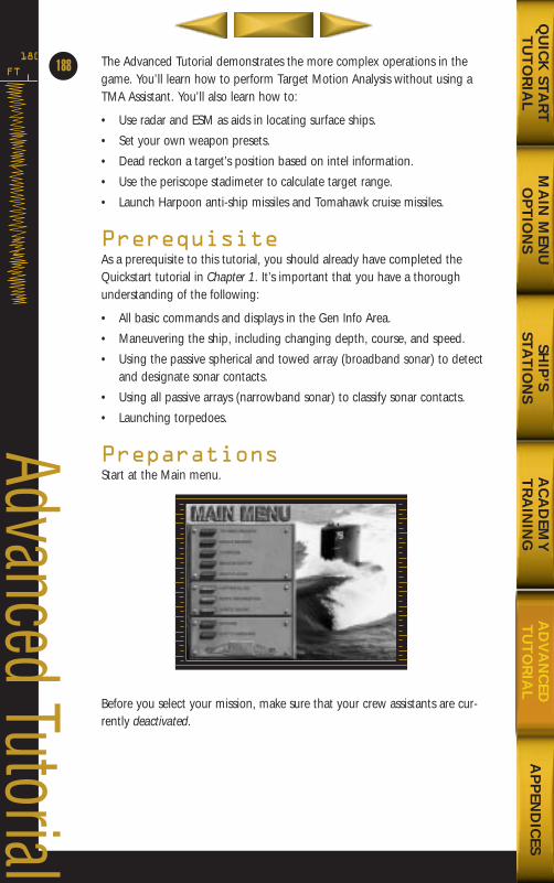
The Advanced Tutorial demonstrates the more complex operations in thegame. You’ll learn how to perform Target Motion Analysis without using aTMA Assistant. You’ll also learn how to:
• Use radar and ESM as aids in locating surface ships.
• Set your own weapon presets.
• Dead reckon a target’s position based on intel information.
• Use the periscope stadimeter to calculate target range.
• Launch Harpoon anti-ship missiles and Tomahawk cruise missiles.
PrerequisiteAs a prerequisite to this tutorial, you should already have completed theQuickstart tutorial in Chapter 1. It’s important that you have a thoroughunderstanding of the following:
• All basic commands and displays in the Gen Info Area.
• Maneuvering the ship, including changing depth, course, and speed.
• Using the passive spherical and towed array (broadband sonar) to detectand designate sonar contacts.
• Using all passive arrays (narrowband sonar) to classify sonar contacts.
• Launching torpedoes.
PreparationsStart at the Main menu.
Before you select your mission, make sure that your crew assistants are cur-rently deactivated.
FT
180
188
Advanced Tutorial
MA
IN M
ENU
OP
TIO
NS
AP
PEN
DIC
ESQ
UIC
K STA
RT
TU
TO
RIA
LSH
IP’S
STAT
ION
SA
CA
DEM
YT
RA
ININ
GA
DV
AN
CED
TU
TO
RIA
L
688(i)/AttackSubChptr5 5/6/98 2:50 PM Page 2
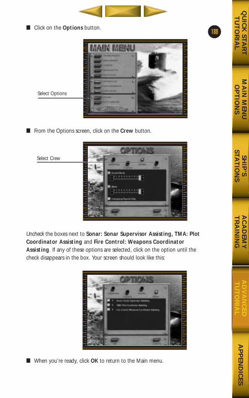
1■ Click on the Options button.
■ From the Options screen, click on the Crew button.
Uncheck the boxes next to Sonar: Sonar Supervisor Assisting, TMA: PlotCoordinator Assisting and Fire Control: Weapons CoordinatorAssisting. If any of these options are selected, click on the option until thecheck disappears in the box. Your screen should look like this:
■ When you’re ready, click OK to return to the Main menu.
189
MA
IN M
ENU
OP
TIO
NS
AP
PEN
DIC
ESQ
UIC
K STA
RT
TU
TO
RIA
LSH
IP’S
STAT
ION
SA
CA
DEM
YT
RA
ININ
GA
DV
AN
CED
TU
TO
RIA
L
Select Options
Select Crew
688(i)/AttackSubChptr5 5/6/98 2:50 PM Page 3
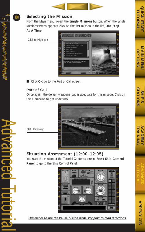
FT
180 Selecting the MissionFrom the Main menu, select the Single Missions button. When the SingleMissions screen appears, click on the first mission in the list, One Step At A Time.
■ Click OK go to the Port of Call screen.
Port of CallOnce again, the default weapons load is adequate for this mission. Click onthe submarine to get underway.
Situation Assessment (12:00–12:05)You start the mission at the Tutorial Contents screen. Select Ship ControlPanel to go to the Ship Control Panel.
Remember to use the Pause button while stopping to read directions.
190
Advanced Tutorial
Click to Highlight
Get Underway
MA
IN M
ENU
OP
TIO
NS
AP
PEN
DIC
ESQ
UIC
K STA
RT
TU
TO
RIA
LSH
IP’S
STAT
ION
SA
CA
DEM
YT
RA
ININ
GA
DV
AN
CED
TU
TO
RIA
L
688(i)/AttackSubChptr5 5/6/98 2:50 PM Page 4
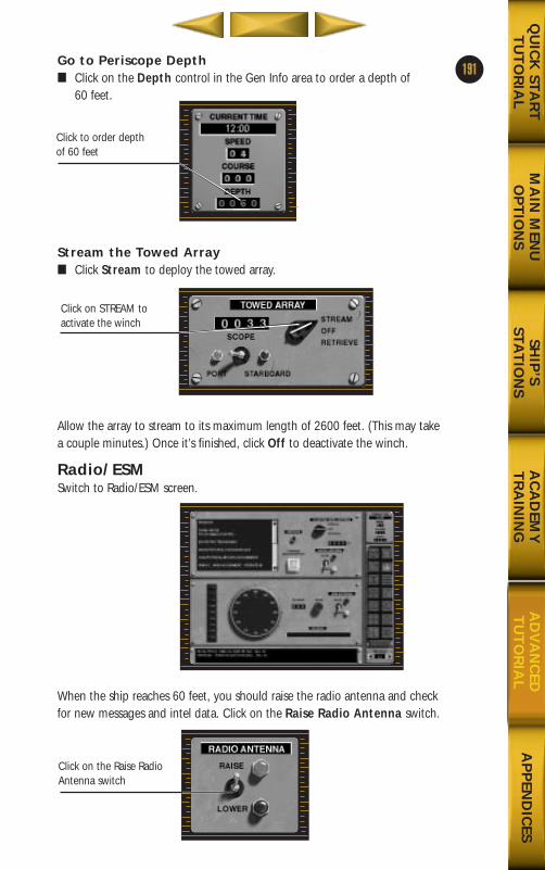
Go to Periscope Depth■ Click on the Depth control in the Gen Info area to order a depth of
60 feet.
Stream the Towed Array■ Click Stream to deploy the towed array.
Allow the array to stream to its maximum length of 2600 feet. (This may takea couple minutes.) Once it’s finished, click Off to deactivate the winch.
Radio/ESMSwitch to Radio/ESM screen.
When the ship reaches 60 feet, you should raise the radio antenna and checkfor new messages and intel data. Click on the Raise Radio Antenna switch.
191
MA
IN M
ENU
OP
TIO
NS
AP
PEN
DIC
ESQ
UIC
K STA
RT
TU
TO
RIA
LSH
IP’S
STAT
ION
SA
CA
DEM
YT
RA
ININ
GA
DV
AN
CED
TU
TO
RIA
L
Click to order depth of 60 feet
Click on STREAM to activate the winch
Click on the Raise RadioAntenna switch
688(i)/AttackSubChptr5 5/6/98 2:51 PM Page 5
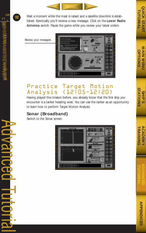
Wait a moment while the mast is raised and a satellite downlink is estab-lished. Eventually you’ll receive a new message. Click on the Lower RadioAntenna switch. Pause the game while you review your latest orders.
Practice Target MotionAnalysis (12:05Ð12:20)Having played this mission before, you already know that the first ship youencounter is a tanker heading west. You can use the tanker as an opportunityto learn how to perform Target Motion Analysis.
Sonar (Broadband)Switch to the Sonar screen.
FT
180
64
Advanced Tutorial
MA
IN M
ENU
OP
TIO
NS
AP
PEN
DIC
ESQ
UIC
K STA
RT
TU
TO
RIA
LSH
IP’S
STAT
ION
SA
CA
DEM
YT
RA
ININ
GA
DV
AN
CED
TU
TO
RIA
L
192
Review your messages
688(i)/AttackSubChptr5 5/6/98 2:51 PM Page 6
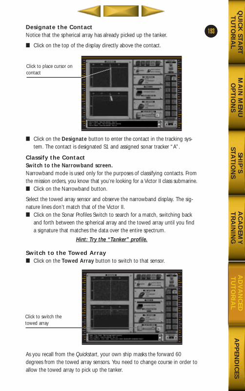
5Designate the ContactNotice that the spherical array has already picked up the tanker.
■ Click on the top of the display directly above the contact.
■ Click on the Designate button to enter the contact in the tracking sys-tem. The contact is designated S1 and assigned sonar tracker “A”.
Classify the ContactSwitch to the Narrowband screen.Narrowband mode is used only for the purposes of classifying contacts. Fromthe mission orders, you know that you’re looking for a Victor II class submarine. ■ Click on the Narrowband button.
Select the towed array sensor and observe the narrowband display. The sig-nature lines don’t match that of the Victor II.■ Click on the Sonar Profiles Switch to search for a match, switching back
and forth between the spherical array and the towed array until you finda signature that matches the data over the entire spectrum.
Hint: Try the “Tanker” profile.
Switch to the Towed Array■ Click on the Towed Array button to switch to that sensor.
As you recall from the Quickstart, your own ship masks the forward 60degrees from the towed array sensors. You need to change course in order toallow the towed array to pick up the tanker.
193
MA
IN M
ENU
OP
TIO
NS
AP
PEN
DIC
ESQ
UIC
K STA
RT
TU
TO
RIA
LSH
IP’S
STAT
ION
SA
CA
DEM
YT
RA
ININ
GA
DV
AN
CED
TU
TO
RIA
L
Click to place cursor oncontact
Click to switch thetowed array
688(i)/AttackSubChptr5 5/6/98 2:51 PM Page 7
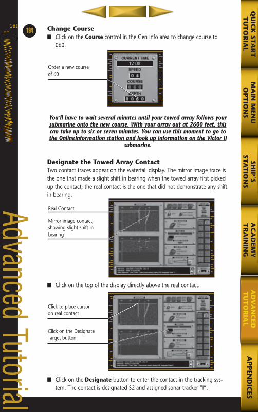
Change Course■ Click on the Course control in the Gen Info area to change course to
060.
You’ll have to wait several minutes until your towed array follows yoursubmarine onto the new course. With your array out at 2600 feet, thiscan take up to six or seven minutes. You can use this moment to go tothe OnlineInformation station and look up information on the Victor II
submarine.
Designate the Towed Array ContactTwo contact traces appear on the waterfall display. The mirror image trace isthe one that made a slight shift in bearing when the towed array first pickedup the contact; the real contact is the one that did not demonstrate any shiftin bearing.
■ Click on the top of the display directly above the real contact.
■ Click on the Designate button to enter the contact in the tracking sys-tem. The contact is designated S2 and assigned sonar tracker “I”.
FT
18064
Advanced Tutorial
MA
IN M
ENU
OP
TIO
NS
AP
PEN
DIC
ESQ
UIC
K STA
RT
TU
TO
RIA
LSH
IP’S
STAT
ION
SA
CA
DEM
YT
RA
ININ
GA
DV
AN
CED
TU
TO
RIA
L
194
Order a new course of 60
Real Contact
Mirror image contact,showing slight shift inbearing
Click to place cursoron real contact
Click on the DesignateTarget button
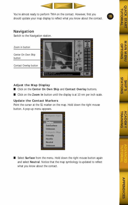
You’re almost ready to perform TMA on the contact. However, first youshould update your map display to reflect what you know about the contact.
NavigationSwitch to the Navigation station.
Adjust the Map Display■ Click on the Center On Own Ship and Contact Overlay buttons.
■ Click on the Zoom In button until the display is at 10 nm per inch scale.
Update the Contact MarkersPoint the cursor at the S1 marker on the map. Hold down the right mousebutton. A pop-up menu appears.
■ Select Surface from the menu. Hold down the right mouse button againand select Neutral. Notice that the map symbology is updated to reflectwhat you know about the contact.
195
MA
IN M
ENU
OP
TIO
NS
AP
PEN
DIC
ESQ
UIC
K STA
RT
TU
TO
RIA
LSH
IP’S
STAT
ION
SA
CA
DEM
YT
RA
ININ
GA
DV
AN
CED
TU
TO
RIA
L
Zoom in button
Center On Own Shipbutton
Contact Overlay button
688(i)/AttackSubChptr5 5/6/98 2:51 PM Page 9
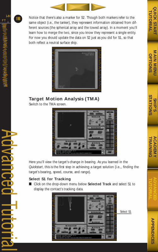
Notice that there’s also a marker for S2. Though both markers refer to thesame object (i.e., the tanker), they represent information obtained from dif-ferent sources (the spherical array and the towed array). In a moment you’lllearn how to merge the two, since you know they represent a single entity.For now you should update the data on S2 just as you did for S1, so thatboth reflect a neutral surface ship.
Target Motion Analysis (TMA)Switch to the TMA screen.
Here you’ll view the target’s change in bearing. As you learned in theQuickstart, this is the first step in achieving a target solution (i.e.,, finding thetarget’s bearing, speed, course, and range).
Select S1 for Tracking■ Click on the drop-down menu below Selected Track and select S1 to
display the contact’s tracking data.
FT
180
64
Advanced Tutorial
MA
IN M
ENU
OP
TIO
NS
AP
PEN
DIC
ESQ
UIC
K STA
RT
TU
TO
RIA
LSH
IP’S
STAT
ION
SA
CA
DEM
YT
RA
ININ
GA
DV
AN
CED
TU
TO
RIA
L
196
Select S1
688(i)/AttackSubChptr5 5/6/98 2:51 PM Page 10
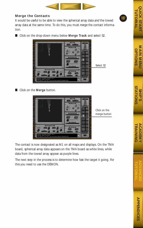
Merge the ContactsIt would be useful to be able to view the spherical array data and the towedarray data at the same time. To do this, you must merge the contact informa-tion.
■ Click on the drop-down menu below Merge Track and select S2.
■ Click on the Merge button.
The contact is now designated as M1 on all maps and displays. On the TMAboard, spherical array data appears on the TMA board as white lines, whiledata from the towed array appear as purple lines.
The next step in the process is to determine how fast the target it going. Forthis you need to use the DEMON.
197
MA
IN M
ENU
OP
TIO
NS
AP
PEN
DIC
ESQ
UIC
K STA
RT
TU
TO
RIA
LSH
IP’S
STAT
ION
SA
CA
DEM
YT
RA
ININ
GA
DV
AN
CED
TU
TO
RIA
L
Select S2
Click on themerge button
688(i)/AttackSubChptr5 5/6/98 2:51 PM Page 11
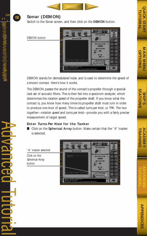
Sonar (DEMON)Switch to the Sonar screen, and then click on the DEMON button.
DEMON stands for demodulated noise, and is used to determine the speed ofa known contact. Here’s how it works.
The DEMON passes the sound of the contact’s propeller through a special-ized set of acoustic filters. This is then fed into a spectrum analyzer, whichdetermines the rotation speed of the propeller shaft. If you know what thecontact is, you know how many times its propeller shaft must turn in orderto produce one knot of speed. This is called turns per knot, or TPK. The twotogether—rotation speed and turns per knot—provide you with a fairly precisemeasurement of target speed.
Enter Turns Per Knot for the Tanker■ Click on the Spherical Array button. Make certain that the “A” tracker
is selected.
FT
180
198
Advanced Tutorial
MA
IN M
ENU
OP
TIO
NS
AP
PEN
DIC
ESQ
UIC
K STA
RT
TU
TO
RIA
LSH
IP’S
STAT
ION
SA
CA
DEM
YT
RA
ININ
GA
DV
AN
CED
TU
TO
RIA
L
DEMON button
“A” tracker selected
Click on theSpherical Array button
688(i)/AttackSubChptr5 5/6/98 2:51 PM Page 12
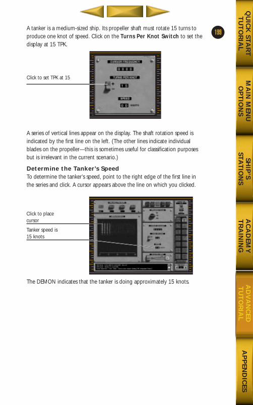
A tanker is a medium-sized ship. Its propeller shaft must rotate 15 turns toproduce one knot of speed. Click on the Turns Per Knot Switch to set thedisplay at 15 TPK.
A series of vertical lines appear on the display. The shaft rotation speed isindicated by the first line on the left. (The other lines indicate individualblades on the propeller—this is sometimes useful for classification purposesbut is irrelevant in the current scenario.)
Determine the Tanker’s SpeedTo determine the tanker’s speed, point to the right edge of the first line inthe series and click. A cursor appears above the line on which you clicked.
The DEMON indicates that the tanker is doing approximately 15 knots.
199
MA
IN M
ENU
OP
TIO
NS
AP
PEN
DIC
ESQ
UIC
K STA
RT
TU
TO
RIA
LSH
IP’S
STAT
ION
SA
CA
DEM
YT
RA
ININ
GA
DV
AN
CED
TU
TO
RIA
L
Click to set TPK at 15
Click to place cursor
Tanker speed is 15 knots
688(i)/AttackSubChptr5 5/6/98 2:51 PM Page 13
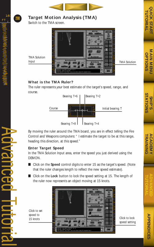
Target Motion Analysis (TMA)Switch to the TMA screen.
What is the TMA Ruler?The ruler represents your best estimate of the target’s speed, range, andcourse.
By moving the ruler around the TMA board, you are in effect telling the FireControl and Weapons computers: “ I estimate the target to be at this range,heading this direction, at this speed.”
Enter Target SpeedIn the TMA Solution Input area, enter the speed you just derived using theDEMON.
■ Click on the Speed control digits to enter 15 as the target’s speed. (Notethat the ruler changes length to reflect the new speed estimate).
■ Click on the Lock button to lock the speed setting at 15. The length ofthe ruler now represents an object moving at 15 knots.
FT
180
200
Advanced Tutorial
MA
IN M
ENU
OP
TIO
NS
AP
PEN
DIC
ESQ
UIC
K STA
RT
TU
TO
RIA
LSH
IP’S
STAT
ION
SA
CA
DEM
YT
RA
ININ
GA
DV
AN
CED
TU
TO
RIA
L
TMA SolutionInput TMA Solution
Initial bearing T
Bearing T+4Bearing T+8
Course
Bearing T+6 Bearing T+2
Click to setspeed to 15 knots Click to lock
speed setting
688(i)/AttackSubChptr5 5/6/98 2:51 PM Page 14
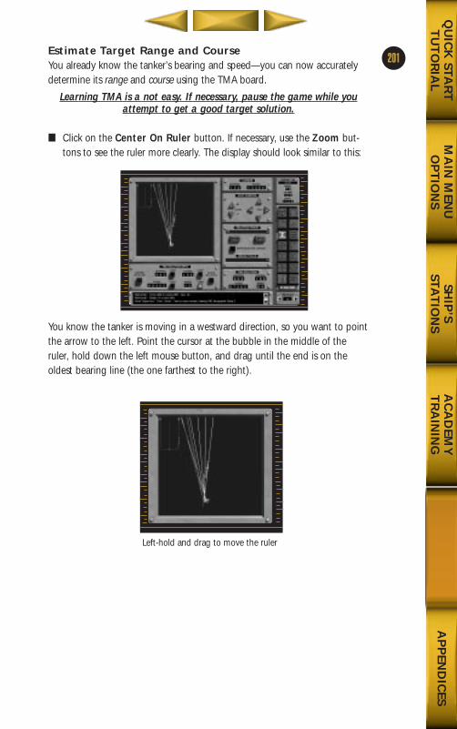
MA
IN M
ENU
OP
TIO
NS
AD
VA
NC
EDT
UT
OR
IAL
AP
PEN
DIC
ESQ
UIC
K STA
RT
TU
TO
RIA
LSH
IP’S
STAT
ION
SA
CA
DEM
YT
RA
ININ
G
201Estimate Target Range and CourseYou already know the tanker’s bearing and speed—you can now accuratelydetermine its range and course using the TMA board.
Learning TMA is a not easy. If necessary, pause the game while youattempt to get a good target solution.
■ Click on the Center On Ruler button. If necessary, use the Zoom but-tons to see the ruler more clearly. The display should look similar to this:
You know the tanker is moving in a westward direction, so you want to pointthe arrow to the left. Point the cursor at the bubble in the middle of theruler, hold down the left mouse button, and drag until the end is on the oldest bearing line (the one farthest to the right).
Left-hold and drag to move the ruler
688(i)/AttackSubChptr5 5/6/98 2:51 PM Page 15
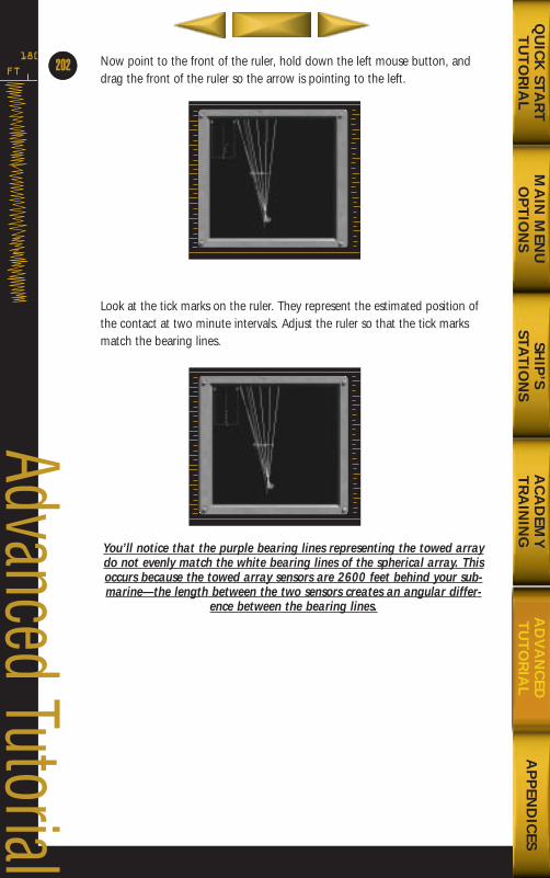
Now point to the front of the ruler, hold down the left mouse button, anddrag the front of the ruler so the arrow is pointing to the left.
Look at the tick marks on the ruler. They represent the estimated position ofthe contact at two minute intervals. Adjust the ruler so that the tick marksmatch the bearing lines.
You’ll notice that the purple bearing lines representing the towed arraydo not evenly match the white bearing lines of the spherical array. Thisoccurs because the towed array sensors are 2600 feet behind your sub-marine—the length between the two sensors creates an angular differ-
ence between the bearing lines.
FT
180
64
Advanced Tutorial
MA
IN M
ENU
OP
TIO
NS
AP
PEN
DIC
ESQ
UIC
K STA
RT
TU
TO
RIA
LSH
IP’S
STAT
ION
SA
CA
DEM
YT
RA
ININ
GA
DV
AN
CED
TU
TO
RIA
L
202
688(i)/AttackSubChptr5 5/6/98 2:51 PM Page 16
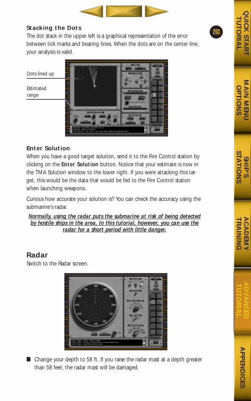
15Stacking the DotsThe dot stack in the upper left is a graphical representation of the errorbetween tick marks and bearing lines. When the dots are on the center line,your analysis is valid.
Enter SolutionWhen you have a good target solution, send it to the Fire Control station byclicking on the Enter Solution button. Notice that your estimate is now inthe TMA Solution window to the lower right. If you were attacking this tar-get, this would be the data that would be fed to the Fire Control stationwhen launching weapons.
Curious how accurate your solution is? You can check the accuracy using thesubmarine’s radar.
Normally, using the radar puts the submarine at risk of being detectedby hostile ships in the area. In this tutorial, however, you can use the
radar for a short period with little danger.
RadarSwitch to the Radar screen.
■ Change your depth to 58 ft. If you raise the radar mast at a depth greaterthan 58 feet, the radar mast will be damaged.
203
MA
IN M
ENU
OP
TIO
NS
AP
PEN
DIC
ESQ
UIC
K STA
RT
TU
TO
RIA
LSH
IP’S
STAT
ION
SA
CA
DEM
YT
RA
ININ
GA
DV
AN
CED
TU
TO
RIA
L
Dots lined up
Estimatedrange
688(i)/AttackSubChptr5 5/6/98 2:52 PM Page 17
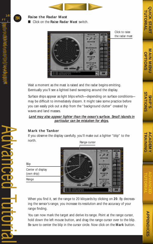
Raise the Radar Mast■ Click on the Raise Radar Mast switch.
Wait a moment as the mast is raised and the radar begins emitting.Eventually you’ll see a lighted band sweeping around the display.
Surface ships appear as light blips which—depending on surface conditions—may be difficult to immediately discern. It might take some practice beforeyou can easily pick out a ship from the “background clutter” created bywaves and land masses.
Land may also appear lighter than the ocean’s surface. Small islands inparticular can be mistaken for ships.
Mark the TankerIf you observe the display carefully, you’ll make out a lighter “blip” to thenorth.
When you find it, set the range to 20 kiloyards by clicking on 20. By decreas-ing the sensor’s range, you increase its resolution and the accuracy of yourrange finding.
You can now mark the target and derive its range. Point at the range cursor,hold down the left mouse button, and drag the range cursor over to the blip.Be sure to center the blip in the cursor circle. Now click on the Mark button.
FT
180
204
Advanced Tutorial
MA
IN M
ENU
OP
TIO
NS
AP
PEN
DIC
ESQ
UIC
K STA
RT
TU
TO
RIA
LSH
IP’S
STAT
ION
SA
CA
DEM
YT
RA
ININ
GA
DV
AN
CED
TU
TO
RIA
L
Click to raisethe radar mast
Blip
Center of display(own ship)
Range
Range cursor
688(i)/AttackSubChptr5 5/6/98 2:52 PM Page 18
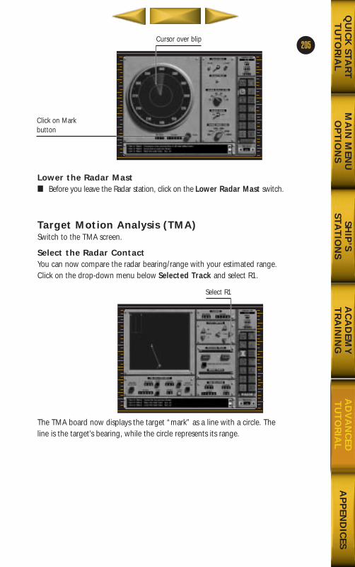
Lower the Radar Mast■ Before you leave the Radar station, click on the Lower Radar Mast switch.
Target Motion Analysis (TMA)Switch to the TMA screen.
Select the Radar ContactYou can now compare the radar bearing/range with your estimated range.Click on the drop-down menu below Selected Track and select R1.
The TMA board now displays the target “mark” as a line with a circle. Theline is the target’s bearing, while the circle represents its range.
205
MA
IN M
ENU
OP
TIO
NS
AP
PEN
DIC
ESQ
UIC
K STA
RT
TU
TO
RIA
LSH
IP’S
STAT
ION
SA
CA
DEM
YT
RA
ININ
GA
DV
AN
CED
TU
TO
RIA
L
Click on Markbutton
Cursor over blip
Select R1
688(i)/AttackSubChptr5 5/6/98 2:52 PM Page 19
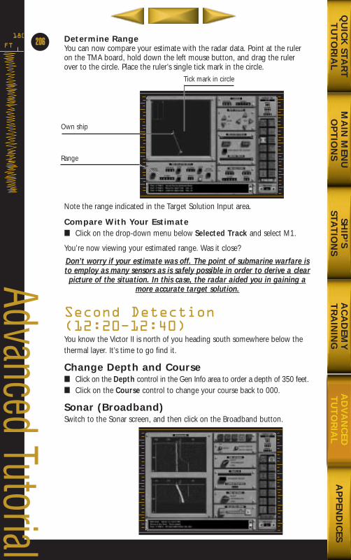
Determine RangeYou can now compare your estimate with the radar data. Point at the ruleron the TMA board, hold down the left mouse button, and drag the rulerover to the circle. Place the ruler’s single tick mark in the circle.
Note the range indicated in the Target Solution Input area.
Compare With Your Estimate■ Click on the drop-down menu below Selected Track and select M1.
You’re now viewing your estimated range. Was it close?
Don’t worry if your estimate was off. The point of submarine warfare isto employ as many sensors as is safely possible in order to derive a clearpicture of the situation. In this case, the radar aided you in gaining a
more accurate target solution.
Second Detection(12:20Ð12:40)You know the Victor II is north of you heading south somewhere below thethermal layer. It’s time to go find it.
Change Depth and Course■ Click on the Depth control in the Gen Info area to order a depth of 350 feet.■ Click on the Course control to change your course back to 000.
Sonar (Broadband)Switch to the Sonar screen, and then click on the Broadband button.
FT
180
206
Advanced Tutorial
MA
IN M
ENU
OP
TIO
NS
AP
PEN
DIC
ESQ
UIC
K STA
RT
TU
TO
RIA
LSH
IP’S
STAT
ION
SA
CA
DEM
YT
RA
ININ
GA
DV
AN
CED
TU
TO
RIA
L
Own ship
Range
Tick mark in circle
688(i)/AttackSubChptr5 5/6/98 2:52 PM Page 20
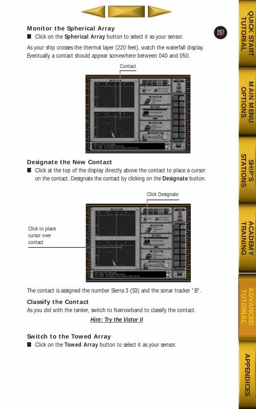
Monitor the Spherical Array■ Click on the Spherical Array button to select it as your sensor.
As your ship crosses the thermal layer (220 feet), watch the waterfall display.Eventually a contact should appear somewhere between 040 and 050.
Designate the New Contact■ Click at the top of the display directly above the contact to place a cursor
on the contact. Designate the contact by clicking on the Designate button.
The contact is assigned the number Sierra 3 (S3) and the sonar tracker “B”.
Classify the ContactAs you did with the tanker, switch to Narrowband to classify the contact.
Hint: Try the Victor II
Switch to the Towed Array■ Click on the Towed Array button to select it as your sensor.
207
MA
IN M
ENU
OP
TIO
NS
AP
PEN
DIC
ESQ
UIC
K STA
RT
TU
TO
RIA
LSH
IP’S
STAT
ION
SA
CA
DEM
YT
RA
ININ
GA
DV
AN
CED
TU
TO
RIA
L
Contact
Click to placecursor overcontact
Click Designate
688(i)/AttackSubChptr5 5/6/98 2:52 PM Page 21
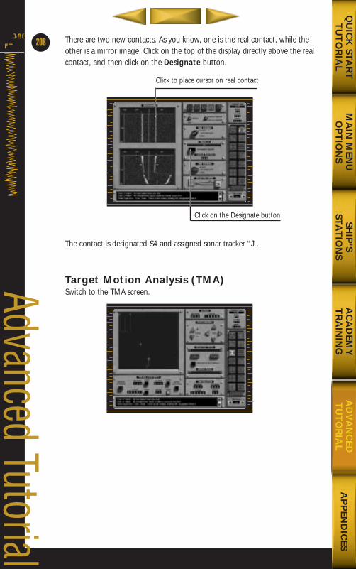
There are two new contacts. As you know, one is the real contact, while theother is a mirror image. Click on the top of the display directly above the realcontact, and then click on the Designate button.
The contact is designated S4 and assigned sonar tracker “J”.
Target Motion Analysis (TMA)Switch to the TMA screen.
FT
180
208
Advanced Tutorial
MA
IN M
ENU
OP
TIO
NS
AP
PEN
DIC
ESQ
UIC
K STA
RT
TU
TO
RIA
LSH
IP’S
STAT
ION
SA
CA
DEM
YT
RA
ININ
GA
DV
AN
CED
TU
TO
RIA
L
Click on the Designate button
Click to place cursor on real contact
688(i)/AttackSubChptr5 5/6/98 2:52 PM Page 22
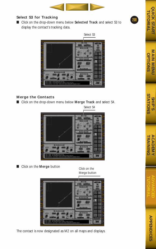
Select S3 for Tracking■ Click on the drop-down menu below Selected Track and select S3 to
display the contact’s tracking data.
Merge the Contacts■ Click on the drop-down menu below Merge Track and select S4.
■ Click on the Merge button
The contact is now designated as M2 on all maps and displays.
209
MA
IN M
ENU
OP
TIO
NS
AP
PEN
DIC
ESQ
UIC
K STA
RT
TU
TO
RIA
LSH
IP’S
STAT
ION
SA
CA
DEM
YT
RA
ININ
GA
DV
AN
CED
TU
TO
RIA
L
Select S3
Select S4
Click on theMerge button
688(i)/AttackSubChptr5 5/6/98 2:52 PM Page 23
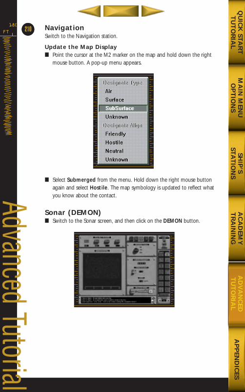
NavigationSwitch to the Navigation station.
Update the Map Display■ Point the cursor at the M2 marker on the map and hold down the right
mouse button. A pop-up menu appears.
■ Select Submerged from the menu. Hold down the right mouse buttonagain and select Hostile. The map symbology is updated to reflect whatyou know about the contact.
Sonar (DEMON)■ Switch to the Sonar screen, and then click on the DEMON button.
FT
180
64
Advanced Tutorial
MA
IN M
ENU
OP
TIO
NS
AP
PEN
DIC
ESQ
UIC
K STA
RT
TU
TO
RIA
LSH
IP’S
STAT
ION
SA
CA
DEM
YT
RA
ININ
GA
DV
AN
CED
TU
TO
RIA
L
210
688(i)/AttackSubChptr5 5/6/98 2:52 PM Page 24
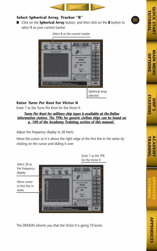
23Select Spherical Array, Tracker “B”■ Click on the Spherical Array button, and then click on the B button to
select B as your current tracker.
Enter Turns Per Knot for Victor IIEnter 7 as the Turns Per Knot for the Victor II.
Turns Per Knot for military ship types is available at the OnlineInformation station. The TPKs for generic civilian ships can be found on
p. 100 of the Academy Training section of this manual.
Adjust the frequency display to 20 hertz.
Move the cursor so it is above the right edge of the first line in the series byclicking on the cursor and sliding it over
The DEMON informs you that the Victor II is going 10 knots.
211
MA
IN M
ENU
OP
TIO
NS
AP
PEN
DIC
ESQ
UIC
K STA
RT
TU
TO
RIA
LSH
IP’S
STAT
ION
SA
CA
DEM
YT
RA
ININ
GA
DV
AN
CED
TU
TO
RIA
L
Spherical arrayselected
Select B as the current tracker
Select 20 asthe Frequencydisplay
Move cursor to first line inseries
Enter 7 as the TPKfor the Victor II
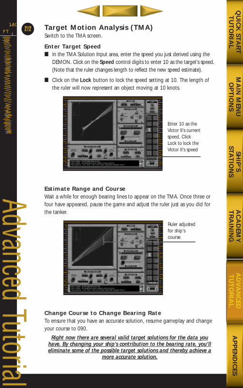
Target Motion Analysis (TMA)Switch to the TMA screen.
Enter Target Speed■ In the TMA Solution Input area, enter the speed you just derived using the
DEMON. Click on the Speed control digits to enter 10 as the target’s speed.(Note that the ruler changes length to reflect the new speed estimate).
■ Click on the Lock button to lock the speed setting at 10. The length ofthe ruler will now represent an object moving at 10 knots.
Estimate Range and CourseWait a while for enough bearing lines to appear on the TMA. Once three orfour have appeared, pause the game and adjust the ruler just as you did forthe tanker.
Change Course to Change Bearing RateTo ensure that you have an accurate solution, resume gameplay and changeyour course to 090.
Right now there are several valid target solutions for the data youhave. By changing your ship’s contribution to the bearing rate, you’lleliminate some of the possible target solutions and thereby achieve a
more accurate solution.
FT
180
212
Advanced Tutorial
MA
IN M
ENU
OP
TIO
NS
AP
PEN
DIC
ESQ
UIC
K STA
RT
TU
TO
RIA
LSH
IP’S
STAT
ION
SA
CA
DEM
YT
RA
ININ
GA
DV
AN
CED
TU
TO
RIA
L
Enter 10 as theVictor II’s currentspeed, ClickLock to lock theVictor II’s speed
Ruler adjustedfor ship’scourse
688(i)/AttackSubChptr5 5/6/98 2:52 PM Page 26
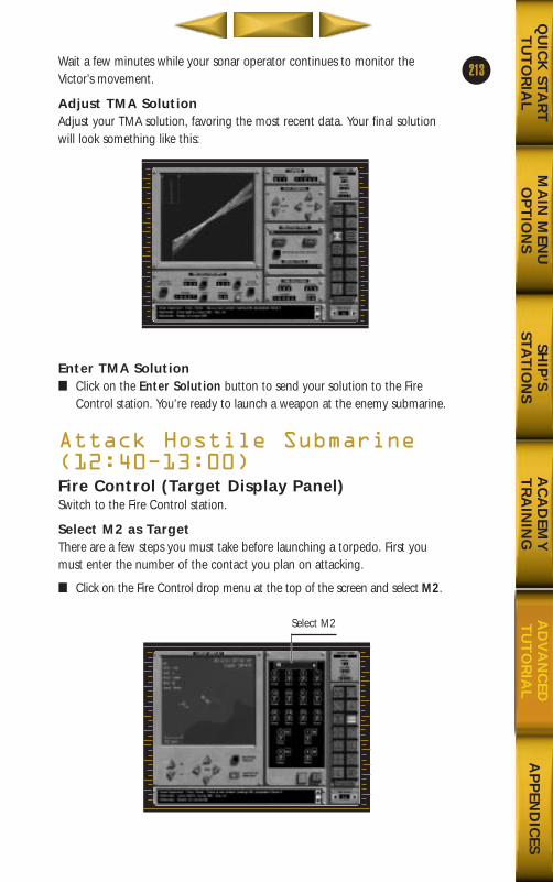
Wait a few minutes while your sonar operator continues to monitor theVictor’s movement.
Adjust TMA SolutionAdjust your TMA solution, favoring the most recent data. Your final solutionwill look something like this:
Enter TMA Solution■ Click on the Enter Solution button to send your solution to the Fire
Control station. You’re ready to launch a weapon at the enemy submarine.
Attack Hostile Submarine(12:40Ð13:00)Fire Control (Target Display Panel)Switch to the Fire Control station.
Select M2 as TargetThere are a few steps you must take before launching a torpedo. First youmust enter the number of the contact you plan on attacking.
■ Click on the Fire Control drop menu at the top of the screen and select M2.
213
MA
IN M
ENU
OP
TIO
NS
AP
PEN
DIC
ESQ
UIC
K STA
RT
TU
TO
RIA
LSH
IP’S
STAT
ION
SA
CA
DEM
YT
RA
ININ
GA
DV
AN
CED
TU
TO
RIA
L
Select M2
688(i)/AttackSubChptr5 5/6/98 2:52 PM Page 27
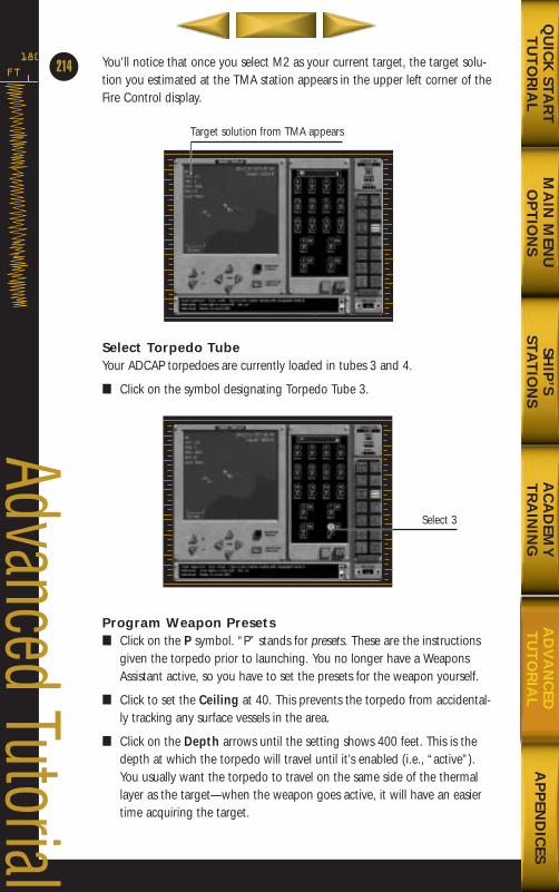
You’ll notice that once you select M2 as your current target, the target solu-tion you estimated at the TMA station appears in the upper left corner of theFire Control display.
Select Torpedo TubeYour ADCAP torpedoes are currently loaded in tubes 3 and 4.
■ Click on the symbol designating Torpedo Tube 3.
Program Weapon Presets■ Click on the P symbol. “P” stands for presets. These are the instructions
given the torpedo prior to launching. You no longer have a WeaponsAssistant active, so you have to set the presets for the weapon yourself.
■ Click to set the Ceiling at 40. This prevents the torpedo from accidental-ly tracking any surface vessels in the area.
■ Click on the Depth arrows until the setting shows 400 feet. This is thedepth at which the torpedo will travel until it’s enabled (i.e., “active”).You usually want the torpedo to travel on the same side of the thermallayer as the target—when the weapon goes active, it will have an easiertime acquiring the target.
FT
180
214
Advanced Tutorial
MA
IN M
ENU
OP
TIO
NS
AP
PEN
DIC
ESQ
UIC
K STA
RT
TU
TO
RIA
LSH
IP’S
STAT
ION
SA
CA
DEM
YT
RA
ININ
GA
DV
AN
CED
TU
TO
RIA
L
Target solution from TMA appears
Select 3
688(i)/AttackSubChptr5 5/6/98 2:53 PM Page 28
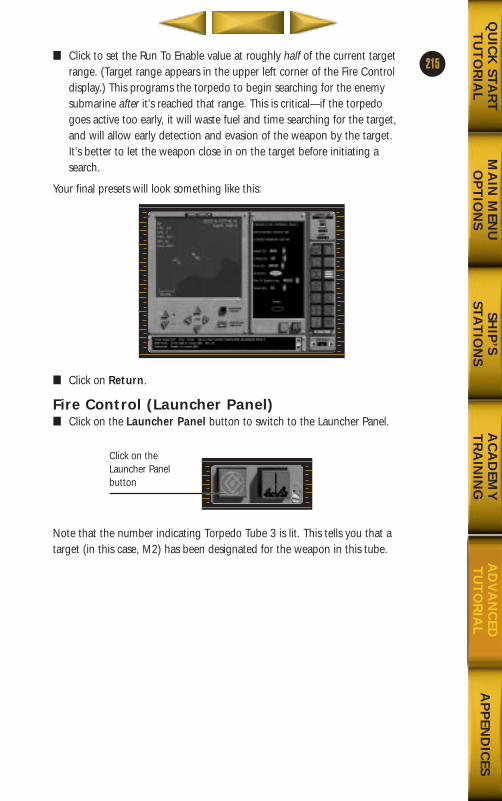
■ Click to set the Run To Enable value at roughly half of the current targetrange. (Target range appears in the upper left corner of the Fire Controldisplay.) This programs the torpedo to begin searching for the enemysubmarine after it’s reached that range. This is critical—if the torpedogoes active too early, it will waste fuel and time searching for the target,and will allow early detection and evasion of the weapon by the target.It’s better to let the weapon close in on the target before initiating asearch.
Your final presets will look something like this:
■ Click on Return.
Fire Control (Launcher Panel)■ Click on the Launcher Panel button to switch to the Launcher Panel.
Note that the number indicating Torpedo Tube 3 is lit. This tells you that atarget (in this case, M2) has been designated for the weapon in this tube.
215
MA
IN M
ENU
OP
TIO
NS
AP
PEN
DIC
ESQ
UIC
K STA
RT
TU
TO
RIA
LSH
IP’S
STAT
ION
SA
CA
DEM
YT
RA
ININ
GA
DV
AN
CED
TU
TO
RIA
L
Click on theLauncher Panelbutton
688(i)/AttackSubChptr5 5/6/98 2:53 PM Page 29
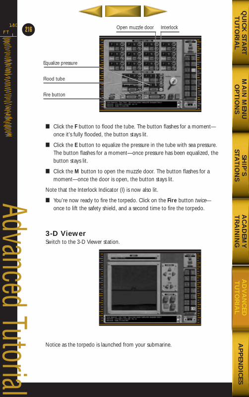
■ Click the F button to flood the tube. The button flashes for a moment—once it’s fully flooded, the button stays lit.
■ Click the E button to equalize the pressure in the tube with sea pressure.The button flashes for a moment—once pressure has been equalized, thebutton stays lit.
■ Click the M button to open the muzzle door. The button flashes for amoment—once the door is open, the button stays lit.
Note that the Interlock Indicator (I) is now also lit.
■ You’re now ready to fire the torpedo. Click on the Fire button twice—once to lift the safety shield, and a second time to fire the torpedo.
3-D ViewerSwitch to the 3-D Viewer station.
Notice as the torpedo is launched from your submarine.
FT
180
216
Advanced Tutorial
MA
IN M
ENU
OP
TIO
NS
AP
PEN
DIC
ESQ
UIC
K STA
RT
TU
TO
RIA
LSH
IP’S
STAT
ION
SA
CA
DEM
YT
RA
ININ
GA
DV
AN
CED
TU
TO
RIA
L
Equalize pressure
Flood tube
Fire button
InterlockOpen muzzle door
688(i)/AttackSubChptr5 5/6/98 2:53 PM Page 30
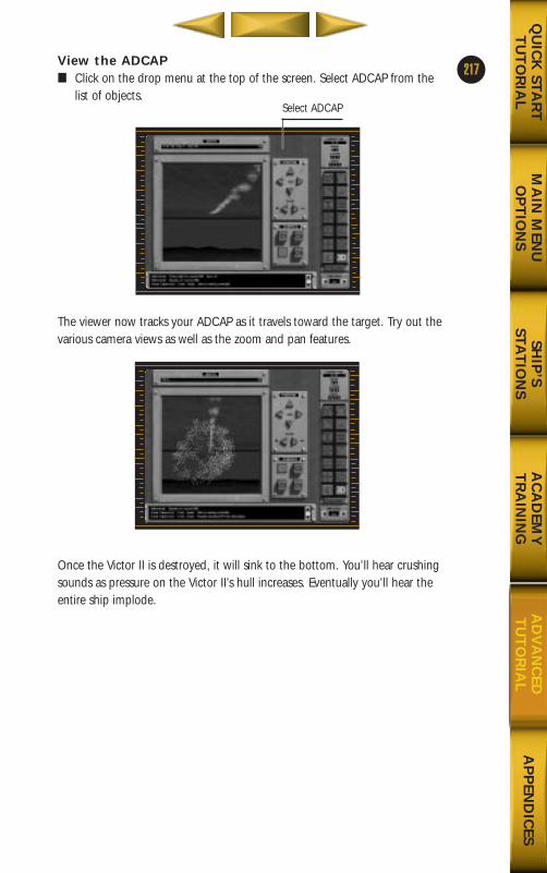
View the ADCAP■ Click on the drop menu at the top of the screen. Select ADCAP from the
list of objects.
The viewer now tracks your ADCAP as it travels toward the target. Try out thevarious camera views as well as the zoom and pan features.
Once the Victor II is destroyed, it will sink to the bottom. You’ll hear crushingsounds as pressure on the Victor II’s hull increases. Eventually you’ll hear theentire ship implode.
217
MA
IN M
ENU
OP
TIO
NS
AP
PEN
DIC
ESQ
UIC
K STA
RT
TU
TO
RIA
LSH
IP’S
STAT
ION
SA
CA
DEM
YT
RA
ININ
GA
DV
AN
CED
TU
TO
RIA
L
Select ADCAP
688(i)/AttackSubChptr5 5/6/98 2:53 PM Page 31
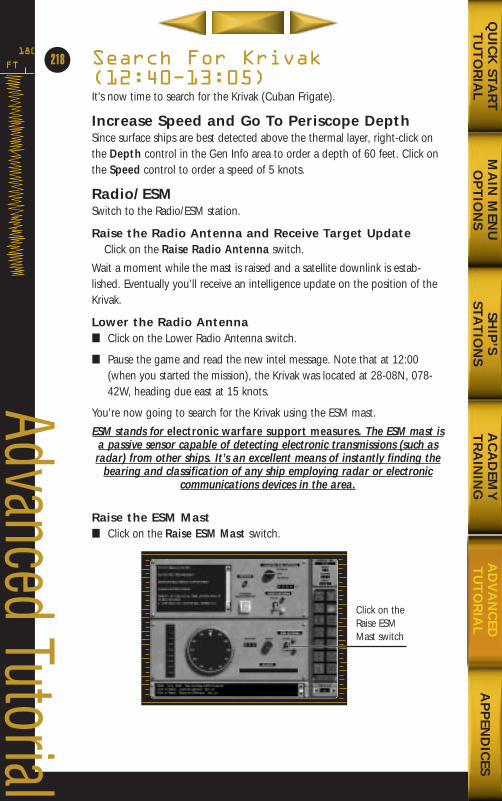
Search For Krivak(12:40Ð13:05)It’s now time to search for the Krivak (Cuban Frigate).
Increase Speed and Go To Periscope DepthSince surface ships are best detected above the thermal layer, right-click onthe Depth control in the Gen Info area to order a depth of 60 feet. Click onthe Speed control to order a speed of 5 knots.
Radio/ESMSwitch to the Radio/ESM station.
Raise the Radio Antenna and Receive Target UpdateClick on the Raise Radio Antenna switch.
Wait a moment while the mast is raised and a satellite downlink is estab-lished. Eventually you’ll receive an intelligence update on the position of theKrivak.
Lower the Radio Antenna■ Click on the Lower Radio Antenna switch.
■ Pause the game and read the new intel message. Note that at 12:00(when you started the mission), the Krivak was located at 28-08N, 078-42W, heading due east at 15 knots.
You’re now going to search for the Krivak using the ESM mast.
ESM stands for electronic warfare support measures. The ESM mast isa passive sensor capable of detecting electronic transmissions (such asradar) from other ships. It’s an excellent means of instantly finding the
bearing and classification of any ship employing radar or electroniccommunications devices in the area.
Raise the ESM Mast■ Click on the Raise ESM Mast switch.
FT
180
218
Advanced Tutorial
MA
IN M
ENU
OP
TIO
NS
AP
PEN
DIC
ESQ
UIC
K STA
RT
TU
TO
RIA
LSH
IP’S
STAT
ION
SA
CA
DEM
YT
RA
ININ
GA
DV
AN
CED
TU
TO
RIA
L
Click on theRaise ESMMast switch
688(i)/AttackSubChptr5 5/6/98 2:53 PM Page 32
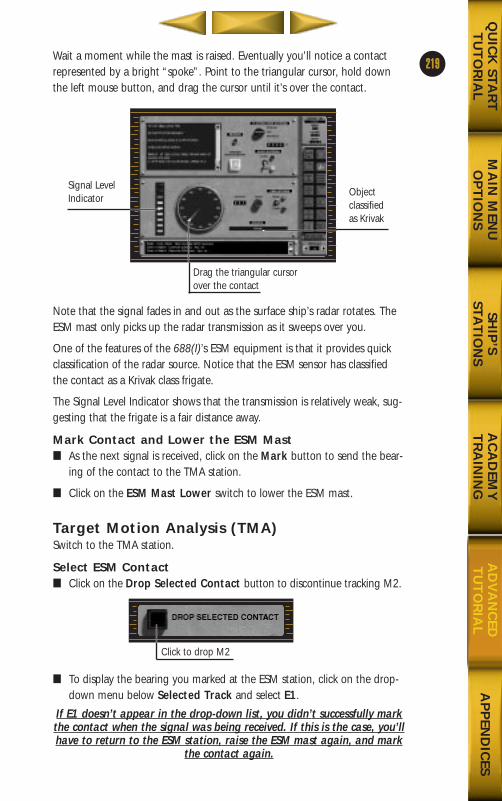
Wait a moment while the mast is raised. Eventually you’ll notice a contactrepresented by a bright “spoke”. Point to the triangular cursor, hold downthe left mouse button, and drag the cursor until it’s over the contact.
Note that the signal fades in and out as the surface ship’s radar rotates. TheESM mast only picks up the radar transmission as it sweeps over you.
One of the features of the 688(I)’s ESM equipment is that it provides quickclassification of the radar source. Notice that the ESM sensor has classifiedthe contact as a Krivak class frigate.
The Signal Level Indicator shows that the transmission is relatively weak, sug-gesting that the frigate is a fair distance away.
Mark Contact and Lower the ESM Mast■ As the next signal is received, click on the Mark button to send the bear-
ing of the contact to the TMA station.
■ Click on the ESM Mast Lower switch to lower the ESM mast.
Target Motion Analysis (TMA)Switch to the TMA station.
Select ESM Contact■ Click on the Drop Selected Contact button to discontinue tracking M2.
■ To display the bearing you marked at the ESM station, click on the drop-down menu below Selected Track and select E1.
If E1 doesn’t appear in the drop-down list, you didn’t successfully markthe contact when the signal was being received. If this is the case, you’llhave to return to the ESM station, raise the ESM mast again, and mark
the contact again.
219
MA
IN M
ENU
OP
TIO
NS
AP
PEN
DIC
ESQ
UIC
K STA
RT
TU
TO
RIA
LSH
IP’S
STAT
ION
SA
CA
DEM
YT
RA
ININ
GA
DV
AN
CED
TU
TO
RIA
L
Signal LevelIndicator
Objectclassifiedas Krivak
Drag the triangular cursorover the contact
Click to drop M2
688(i)/AttackSubChptr5 5/6/98 2:53 PM Page 33
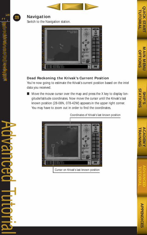
NavigationSwitch to the Navigation station.
Dead Reckoning the Krivak’s Current PositionYou’re now going to estimate the Krivak’s current position based on the inteldata you received.
■ Move the mouse cursor over the map and press the X key to display lon-gitude/latitude coordinates. Now move the cursor until the Krivak’s lastknown position (28-08N, 078-42W) appears in the upper right corner.You may have to zoom out in order to find the coordinates.
FT
180
220
Advanced Tutorial
MA
IN M
ENU
OP
TIO
NS
AP
PEN
DIC
ESQ
UIC
K STA
RT
TU
TO
RIA
LSH
IP’S
STAT
ION
SA
CA
DEM
YT
RA
ININ
GA
DV
AN
CED
TU
TO
RIA
L
Cursor on Krivak’s last known position
Coordinates of Krivak’s last known position
688(i)/AttackSubChptr5 5/6/98 2:53 PM Page 34
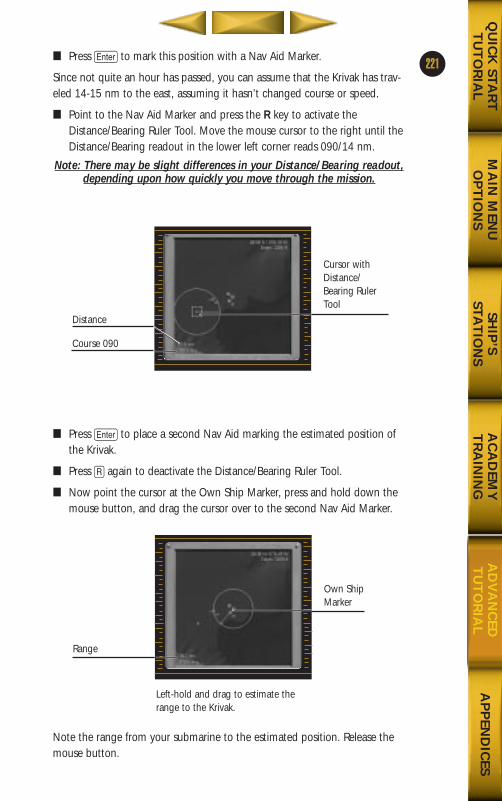
■ Press e to mark this position with a Nav Aid Marker.
Since not quite an hour has passed, you can assume that the Krivak has trav-eled 14-15 nm to the east, assuming it hasn’t changed course or speed.
■ Point to the Nav Aid Marker and press the R key to activate theDistance/Bearing Ruler Tool. Move the mouse cursor to the right until theDistance/Bearing readout in the lower left corner reads 090/14 nm.
Note: There may be slight differences in your Distance/Bearing readout,depending upon how quickly you move through the mission.
■ Press e to place a second Nav Aid marking the estimated position ofthe Krivak.
■ Press R again to deactivate the Distance/Bearing Ruler Tool.
■ Now point the cursor at the Own Ship Marker, press and hold down themouse button, and drag the cursor over to the second Nav Aid Marker.
Note the range from your submarine to the estimated position. Release themouse button.
221
MA
IN M
ENU
OP
TIO
NS
AP
PEN
DIC
ESQ
UIC
K STA
RT
TU
TO
RIA
LSH
IP’S
STAT
ION
SA
CA
DEM
YT
RA
ININ
GA
DV
AN
CED
TU
TO
RIA
L
Distance
Course 090
Cursor withDistance/Bearing RulerTool
Range
Own ShipMarker
Left-hold and drag to estimate therange to the Krivak.
688(i)/AttackSubChptr5 5/6/98 2:53 PM Page 35
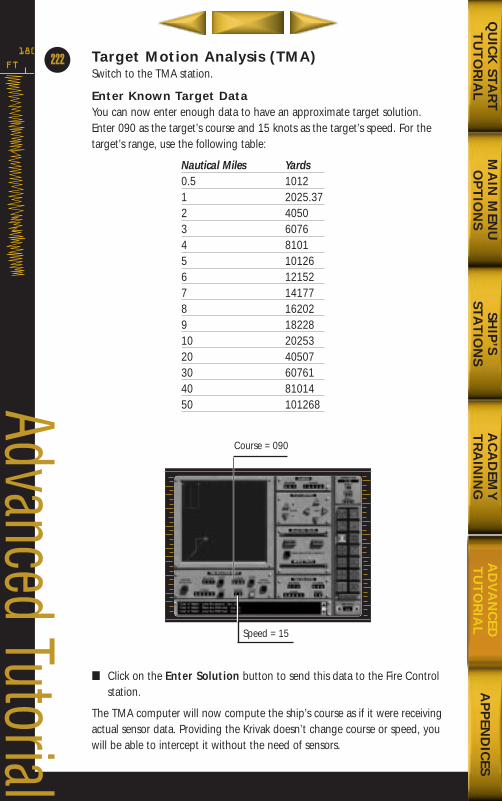
Target Motion Analysis (TMA)Switch to the TMA station.
Enter Known Target DataYou can now enter enough data to have an approximate target solution.Enter 090 as the target’s course and 15 knots as the target’s speed. For thetarget’s range, use the following table:
Nautical Miles Yards0.5 10121 2025.372 40503 60764 81015 101266 121527 141778 162029 1822810 2025320 4050730 6076140 8101450 101268
■ Click on the Enter Solution button to send this data to the Fire Controlstation.
The TMA computer will now compute the ship’s course as if it were receivingactual sensor data. Providing the Krivak doesn’t change course or speed, youwill be able to intercept it without the need of sensors.
FT
180
222
Advanced Tutorial
MA
IN M
ENU
OP
TIO
NS
AP
PEN
DIC
ESQ
UIC
K STA
RT
TU
TO
RIA
LSH
IP’S
STAT
ION
SA
CA
DEM
YT
RA
ININ
GA
DV
AN
CED
TU
TO
RIA
L
Speed = 15
Course = 090
688(i)/AttackSubChptr5 5/6/98 2:53 PM Page 36
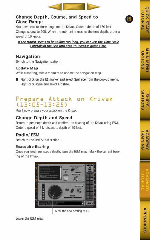
Change Depth, Course, and Speed to Close RangeYou now need to close range on the Krivak. Order a depth of 150 feet.Change course to 205. When the submarine reaches the new depth, order aspeed of 10 knots.
If the transit seems to be taking too long, you can use the Time ScaleControls in the Gen Info area to increase game time.
NavigationSwitch to the Navigation station.
Update MapWhile transiting, take a moment to update the navigation map.
■ Right-click on the E1 marker and select Surface from the pop-up menu.Right-click again and select Hostile.
Prepare Attack on Krivak(13:05Ð13:25)You’ll now prepare your attack on the Krivak.
Change Depth and SpeedReturn to periscope depth and confirm the bearing of the Krivak using ESM.Order a speed of 5 knots and a depth of 60 feet.
Radio/ESMSwitch to the Radio/ESM station.
Reacquire BearingOnce you reach periscope depth, raise the ESM mast. Mark the current bear-ing of the Krivak.
Lower the ESM mast.
223
MA
IN M
ENU
OP
TIO
NS
AP
PEN
DIC
ESQ
UIC
K STA
RT
TU
TO
RIA
LSH
IP’S
STAT
ION
SA
CA
DEM
YT
RA
ININ
GA
DV
AN
CED
TU
TO
RIA
L
Mark the new bearing of E1
688(i)/AttackSubChptr5 5/6/98 2:53 PM Page 37
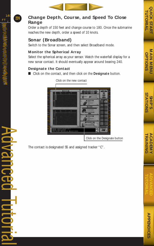
Change Depth, Course, and Speed To CloseRangeOrder a depth of 150 feet and change course to 180. Once the submarinereaches the new depth, order a speed of 10 knots.
Sonar (Broadband)Switch to the Sonar screen, and then select Broadband mode.
Monitor the Spherical ArraySelect the spherical array as your sensor. Watch the waterfall display for anew sonar contact. It should eventually appear around bearing 240.
Designate the Contact■ Click on the contact, and then click on the Designate button.
The contact is designated S5 and assigned tracker “C”.
FT
180
224
Advanced Tutorial
MA
IN M
ENU
OP
TIO
NS
AP
PEN
DIC
ESQ
UIC
K STA
RT
TU
TO
RIA
LSH
IP’S
STAT
ION
SA
CA
DEM
YT
RA
ININ
GA
DV
AN
CED
TU
TO
RIA
L
Click on the Designate button
Click on the new contact
688(i)/AttackSubChptr5 5/6/98 2:53 PM Page 38
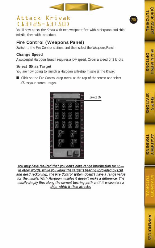
Attack Krivak(13:25Ð13:50)You’ll now attack the Krivak with two weapons: first with a Harpoon anti-shipmissile, then with torpedoes.
Fire Control (Weapons Panel)Switch to the Fire Control station, and then select the Weapons Panel.
Change SpeedA successful Harpoon launch requires a low speed. Order a speed of 3 knots.
Select S5 as TargetYou are now going to launch a Harpoon anti-ship missile at the Krivak.
■ Click on the Fire Control drop menu at the top of the screen and selectS5 as your current target.
You may have realized that you don’t have range information for S5—in other words, while you know the target’s bearing (provided by ESM
and dead reckoning), the Fire Control system doesn’t have a range valuefor the missile. With Harpoon missiles it doesn’t make a difference. Themissile simply flies along the current bearing path until it encounters a
ship, which it then attacks.
225
MA
IN M
ENU
OP
TIO
NS
AP
PEN
DIC
ESQ
UIC
K STA
RT
TU
TO
RIA
LSH
IP’S
STAT
ION
SA
CA
DEM
YT
RA
ININ
GA
DV
AN
CED
TU
TO
RIA
L
Select S5
688(i)/AttackSubChptr5 5/6/98 2:53 PM Page 39
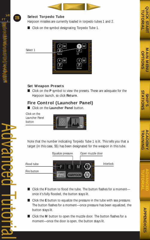
Select Torpedo TubeHarpoon missiles are currently loaded in torpedo tubes 1 and 2.
■ Click on the symbol designating Torpedo Tube 1.
Set Weapon Presets■ Click on the P symbol to view the presets. These are adequate for the
Harpoon launch, so click Return.
Fire Control (Launcher Panel)■ Click on the Launcher Panel button.
Note that the number indicating Torpedo Tube 1 is lit. This tells you that atarget (in this case, S5) has been designated for the weapon in this tube.
■ Click the F button to flood the tube. The button flashes for a moment—once it’s fully flooded, the button stays lit.
■ Click the E button to equalize the pressure in the tube with sea pressure.The button flashes for a moment—once pressure has been equalized, thebutton stays lit.
■ Click the M button to open the muzzle door. The button flashes for amoment—once the door is open, the button stays lit.
FT
180
226
Advanced Tutorial
MA
IN M
ENU
OP
TIO
NS
AP
PEN
DIC
ESQ
UIC
K STA
RT
TU
TO
RIA
LSH
IP’S
STAT
ION
SA
CA
DEM
YT
RA
ININ
GA
DV
AN
CED
TU
TO
RIA
L
Select 1
Click on theLauncher Panelbutton
Flood tube
Fire button
Interlock
Open muzzle doorEqualize pressure
688(i)/AttackSubChptr5 5/6/98 2:53 PM Page 40
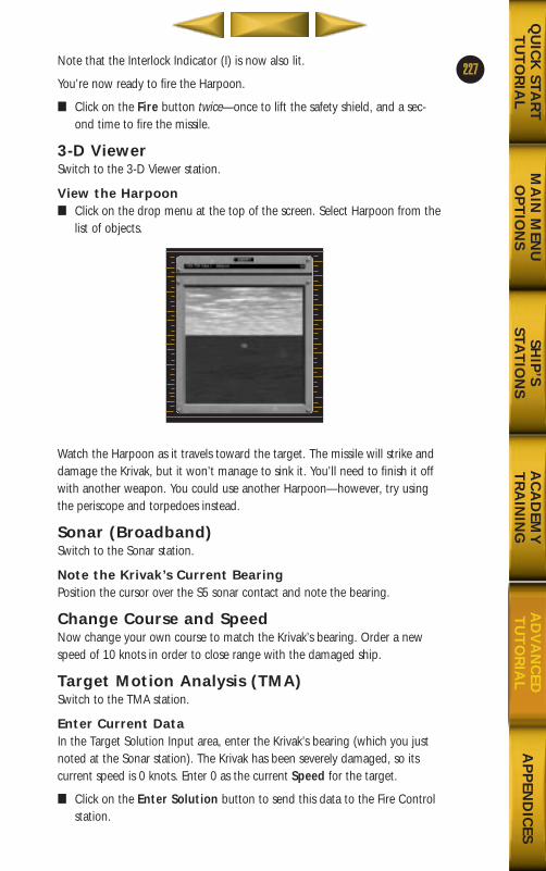
Note that the Interlock Indicator (I) is now also lit.
You’re now ready to fire the Harpoon.
■ Click on the Fire button twice—once to lift the safety shield, and a sec-ond time to fire the missile.
3-D ViewerSwitch to the 3-D Viewer station.
View the Harpoon■ Click on the drop menu at the top of the screen. Select Harpoon from the
list of objects.
Watch the Harpoon as it travels toward the target. The missile will strike anddamage the Krivak, but it won’t manage to sink it. You’ll need to finish it offwith another weapon. You could use another Harpoon—however, try usingthe periscope and torpedoes instead.
Sonar (Broadband)Switch to the Sonar station.
Note the Krivak’s Current BearingPosition the cursor over the S5 sonar contact and note the bearing.
Change Course and SpeedNow change your own course to match the Krivak’s bearing. Order a newspeed of 10 knots in order to close range with the damaged ship.
Target Motion Analysis (TMA)Switch to the TMA station.
Enter Current DataIn the Target Solution Input area, enter the Krivak’s bearing (which you justnoted at the Sonar station). The Krivak has been severely damaged, so itscurrent speed is 0 knots. Enter 0 as the current Speed for the target.
■ Click on the Enter Solution button to send this data to the Fire Controlstation.
227
MA
IN M
ENU
OP
TIO
NS
AP
PEN
DIC
ESQ
UIC
K STA
RT
TU
TO
RIA
LSH
IP’S
STAT
ION
SA
CA
DEM
YT
RA
ININ
GA
DV
AN
CED
TU
TO
RIA
L
688(i)/AttackSubChptr5 5/6/98 2:54 PM Page 41
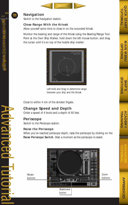
NavigationSwitch to the Navigation station.
Close Range With the KrivakAllow yourself some time to close in on the wounded Krivak.
Monitor the bearing and range of the Krivak using the Bearing/Range Tool.Point at the Own Ship Marker, hold down the left mouse button, and dragthe cursor until it’s on top of the hostile ship marker:
Close to within 4 nm of the stricken frigate.
Change Speed and DepthOrder a speed of 4 knots and a depth of 60 feet.
PeriscopeSwitch to the Periscope station.
Raise the PeriscopeWhen you’ve reached periscope depth, raise the periscope by clicking on theRaise Periscope Switch. Wait a moment as the periscope is raised.
FT
180
228
Advanced Tutorial
MA
IN M
ENU
OP
TIO
NS
AP
PEN
DIC
ESQ
UIC
K STA
RT
TU
TO
RIA
LSH
IP’S
STAT
ION
SA
CA
DEM
YT
RA
ININ
GA
DV
AN
CED
TU
TO
RIA
L
Left-hold and drag to determine rangebetween your ship and the Krivak
Rotatebuttons
Zoom buttons
Stadimeterbutton
688(i)/AttackSubChptr5 5/6/98 2:54 PM Page 42
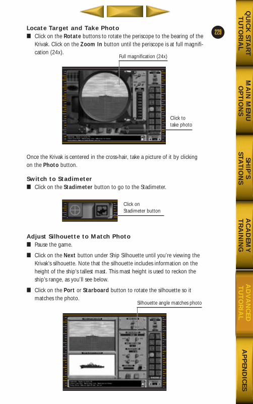
Locate Target and Take Photo■ Click on the Rotate buttons to rotate the periscope to the bearing of the
Krivak. Click on the Zoom In button until the periscope is at full magnifi-cation (24x).
Once the Krivak is centered in the cross-hair, take a picture of it by clickingon the Photo button.
Switch to Stadimeter■ Click on the Stadimeter button to go to the Stadimeter.
Adjust Silhouette to Match Photo■ Pause the game.
■ Click on the Next button under Ship Silhouette until you’re viewing theKrivak’s silhouette. Note that the silhouette includes information on theheight of the ship’s tallest mast. This mast height is used to reckon theship’s range, as you’ll see below.
■ Click on the Port or Starboard button to rotate the silhouette so itmatches the photo.
229
MA
IN M
ENU
OP
TIO
NS
AP
PEN
DIC
ESQ
UIC
K STA
RT
TU
TO
RIA
LSH
IP’S
STAT
ION
SA
CA
DEM
YT
RA
ININ
GA
DV
AN
CED
TU
TO
RIA
L
Click to take photo
Full magnification (24x)
Click onStadimeter button
Silhouette angle matches photo
688(i)/AttackSubChptr5 5/6/98 2:54 PM Page 43

Determine RangeRange is determined using the Up and Down buttons under Image Adjust.Click on the buttons. You’ll notice that half of the photo shifts as you pressUp or Down. The trick is to lower the top of the highest mast such that it’slevel with the waterline on the opposite half of the image.
Using mast height data, the stadimeter calculates the range to the target.Click on the Mark button to send the visual solution to the TMA and FireControl stations.
Fire Control (Launcher Panel)Switch to the Fire Control station.
Reload ADCAP in Torpedo Tube 3It may take two torpedoes to finish off the Krivak. (It may take only one, butit’s better to be safe rather than sorry.) You’ll need to reload Torpedo Tube 3with another ADCAP.
■ Click on the M button to close the muzzle door. The button flashes brieflybefore the tube is returned to its pre-launch state.
■ Click on Empty until the word ADCAP appears. The button flashes brieflywhile the torpedo is loaded into the tube.
Note that the number indicating Torpedo Tube 1 is lit. This tells you that atarget (in this case, S5) has been designated for the weapon in this tube.
Fire Control (Target Display Panel)■ Click on the Weapons Panel button.
FT
180
230
Advanced Tutorial
MA
IN M
ENU
OP
TIO
NS
AP
PEN
DIC
ESQ
UIC
K STA
RT
TU
TO
RIA
LSH
IP’S
STAT
ION
SA
CA
DEM
YT
RA
ININ
GA
DV
AN
CED
TU
TO
RIA
L
Tallest mast levelwith waterline
Range to target
688(i)/AttackSubChptr5 5/6/98 2:54 PM Page 44
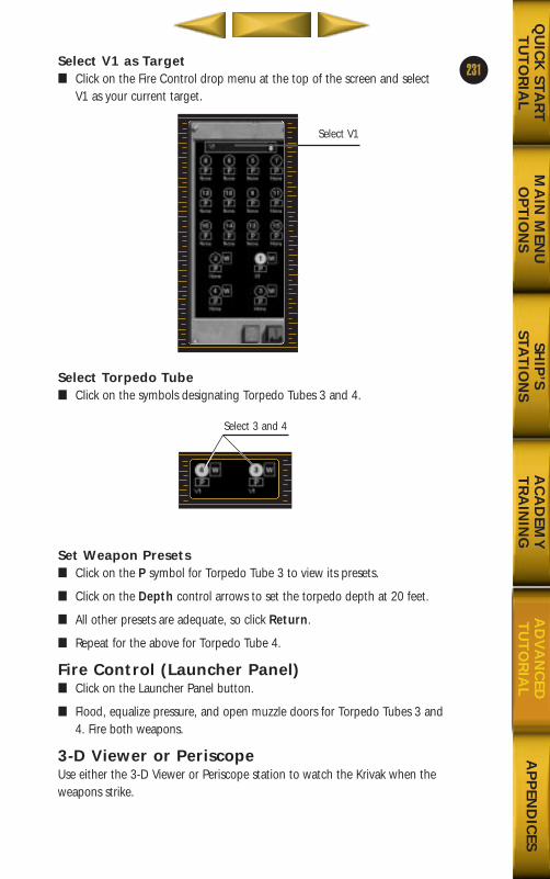
Select V1 as Target■ Click on the Fire Control drop menu at the top of the screen and select
V1 as your current target.
Select Torpedo Tube■ Click on the symbols designating Torpedo Tubes 3 and 4.
Set Weapon Presets■ Click on the P symbol for Torpedo Tube 3 to view its presets.
■ Click on the Depth control arrows to set the torpedo depth at 20 feet.
■ All other presets are adequate, so click Return.
■ Repeat for the above for Torpedo Tube 4.
Fire Control (Launcher Panel)■ Click on the Launcher Panel button.
■ Flood, equalize pressure, and open muzzle doors for Torpedo Tubes 3 and4. Fire both weapons.
3-D Viewer or PeriscopeUse either the 3-D Viewer or Periscope station to watch the Krivak when theweapons strike.
231
MA
IN M
ENU
OP
TIO
NS
AP
PEN
DIC
ESQ
UIC
K STA
RT
TU
TO
RIA
LSH
IP’S
STAT
ION
SA
CA
DEM
YT
RA
ININ
GA
DV
AN
CED
TU
TO
RIA
L
Select V1
Select 3 and 4
688(i)/AttackSubChptr5 5/6/98 2:54 PM Page 45
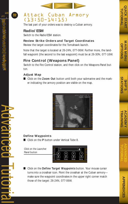
Attack Cuban Armory(13:50Ð14:15)The last part of your orders was to destroy a Cuban armory.
Radio/ESMSwitch to the Radio/ESM station.
Review Strike Orders and Target CoordinatesReview the target coordinates for the Tomahawk launch.
Note that the target is located at 26-24N, 077-06W. Further more, the land-fall waypoint (the second to the last waypoint) must be at 26-30N, 077-16W.
Fire Control (Weapons Panel)Switch to the Fire Control station, and then click on the Weapons Panel but-ton.
Adjust Map■ Click on the Zoom Out button until both your submarine and the mark-
er indicating the armory position are visible on the map.
Define Waypoints■ Click on the P button under Vertical Tube 8.
■ Click on the Define Target Waypoints button. Your mouse cursorturns into a crosshair icon. Point the crosshair at the Cuban armory—make sure the waypoint coordinates in the upper right corner matchthose of the target: 26-24N, 077-06W.
FT
180
232
Advanced Tutorial
MA
IN M
ENU
OP
TIO
NS
AP
PEN
DIC
ESQ
UIC
K STA
RT
TU
TO
RIA
LSH
IP’S
STAT
ION
SA
CA
DEM
YT
RA
ININ
GA
DV
AN
CED
TU
TO
RIA
L
Click on the LauncherPanel button
688(i)/AttackSubChptr5 5/6/98 2:54 PM Page 46
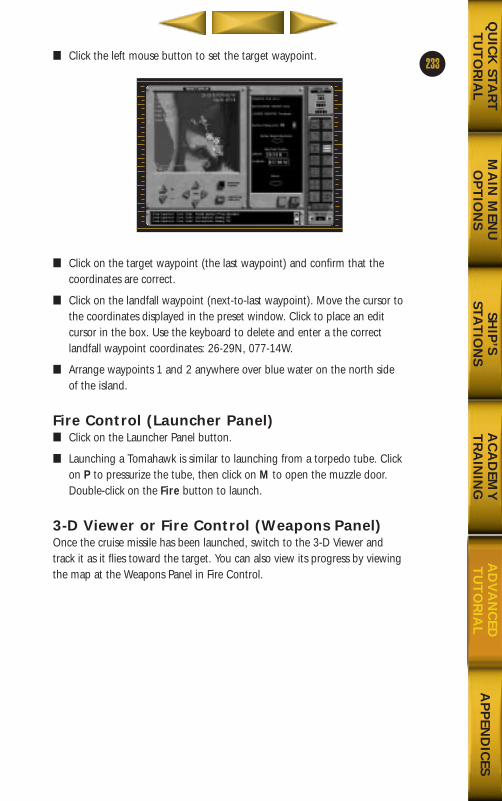
■ Click the left mouse button to set the target waypoint.
■ Click on the target waypoint (the last waypoint) and confirm that thecoordinates are correct.
■ Click on the landfall waypoint (next-to-last waypoint). Move the cursor tothe coordinates displayed in the preset window. Click to place an editcursor in the box. Use the keyboard to delete and enter a the correctlandfall waypoint coordinates: 26-29N, 077-14W.
■ Arrange waypoints 1 and 2 anywhere over blue water on the north sideof the island.
Fire Control (Launcher Panel)■ Click on the Launcher Panel button.
■ Launching a Tomahawk is similar to launching from a torpedo tube. Clickon P to pressurize the tube, then click on M to open the muzzle door.Double-click on the Fire button to launch.
3-D Viewer or Fire Control (Weapons Panel)Once the cruise missile has been launched, switch to the 3-D Viewer andtrack it as it flies toward the target. You can also view its progress by viewingthe map at the Weapons Panel in Fire Control.
233
MA
IN M
ENU
OP
TIO
NS
AP
PEN
DIC
ESQ
UIC
K STA
RT
TU
TO
RIA
LSH
IP’S
STAT
ION
SA
CA
DEM
YT
RA
ININ
GA
DV
AN
CED
TU
TO
RIA
L
688(i)/AttackSubChptr5 5/6/98 2:54 PM Page 47
Radio/ESMWhen you’ve successfully destroyed the Cuban armory, switch to theRadio/ESM station.
End Mission■ To end the mission and read a debriefing on your performance, double-
click on the Transmit Mission Report button.
Congratulations on a job well done. You now should be ready to tackle anentire 688(I) campaign on your own.
FT
180
234
Advanced Tutorial
MA
IN M
ENU
OP
TIO
NS
AP
PEN
DIC
ESQ
UIC
K STA
RT
TU
TO
RIA
LSH
IP’S
STAT
ION
SA
CA
DEM
YT
RA
ININ
GA
DV
AN
CED
TU
TO
RIA
L
688(i)/AttackSubChptr5 5/6/98 2:54 PM Page 48
MA
IN M
ENU
OP
TIO
NS
AD
VA
NC
EDT
UT
OR
IAL
QU
ICK
STAR
TT
UT
OR
IAL
SHIP
’S STA
TIO
NS
AC
AD
EMY
TR
AIN
ING
AP
PEN
DIC
ES
688(i)/AttackSubAppdcsB 5/6/98 3:50 PM Page 11
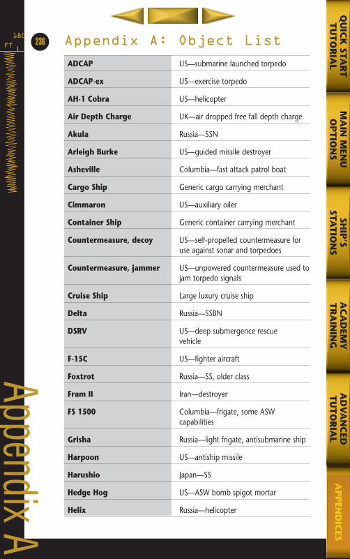
FT
180236
Appendix A
Appendix A: Object List
ADCAP US—submarine launched torpedo
ADCAP-ex US—exercise torpedo
AH-1 Cobra US—helicopter
Air Depth Charge UK—air dropped free fall depth charge
Akula Russia—SSN
Arleigh Burke US—guided missile destroyer
Asheville Columbia—fast attack patrol boat
Cargo Ship Generic cargo carrying merchant
Cimmaron US—auxiliary oiler
Container Ship Generic container carrying merchant
Countermeasure, decoy US—self-propelled countermeasure for use against sonar and torpedoes
Countermeasure, jammer US—unpowered countermeasure used tojam torpedo signals
Cruise Ship Large luxury cruise ship
Delta Russia—SSBN
DSRV US—deep submergence rescue vehicle
F-15C US—fighter aircraft
Foxtrot Russia—SS, older class
Fram II Iran—destroyer
FS 1500 Columbia—frigate, some ASW capabilities
Grisha Russia—light frigate, antisubmarine ship
Harpoon US—antiship missile
Harushio Japan—SS
Hedge Hog US—ASW bomb spigot mortar
Helix Russia—helicopter
MA
IN M
ENU
OP
TIO
NS
AD
VA
NC
EDT
UT
OR
IAL
QU
ICK
STAR
TT
UT
OR
IAL
SHIP
’SSTA
TIO
NS
AC
AD
EMY
TR
AIN
ING
AP
PEN
DIC
ES
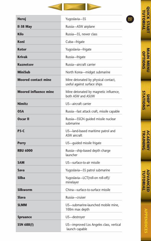
MA
IN M
ENU
OP
TIO
NS
AD
VA
NC
EDT
UT
OR
IAL
QU
ICK
STAR
TT
UT
OR
IAL
SHIP
’SSTA
TIO
NS
AC
AD
EMY
TR
AIN
ING
AP
PEN
DIC
ES
237Heroj Yugoslavia—SS
Il-38 May Russia—ASW airplane
Kilo Russia—SS, newer class
Koni Cuba—frigate
Kotor Yugoslavia—frigate
Krivak Russia—frigate
Kuznetsov Russia—aircraft carrier
MiniSub North Korea—midget submarine
Moored contact mine Mine detonated by physical contact, useful against surface ships
Moored influence mine Mine detonated by magnetic influence, both ASW and ASUW
Nimitz US—aircraft carrier
OSA Russia—fast attack craft, missile capable
Oscar II Russia—SSGN guided missile nuclear submarine
P3-C US—land-based maritime patrol and ASW aircraft
Perry US—guided missile frigate
RBU 6000 Russia—ship-based depth charge launcher
SAM US—surface-to-air missile
Sava Yugoslavia—SS patrol submarine
Silba Yugoslavia—LCT(roll-on roll-off)/minelayer
Silkworm China—surface-to-surface missile
Slava Russia—cruiser
SLMM US—submarine-launched mobile mine, 100m max depth
Spruance US—destroyer
SSN 688(I) US—improved Los Angeles class, verticallaunch capable
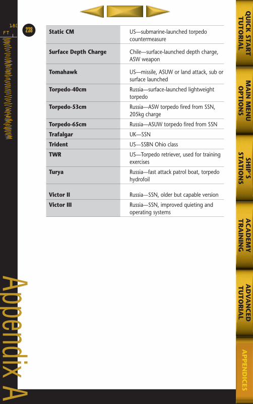
FT
180238
Appendix A
Static CM US—submarine-launched torpedo countermeasure
Surface Depth Charge Chile—surface-launched depth charge, ASW weapon
Tomahawk US—missile, ASUW or land attack, sub orsurface launched
Torpedo-40cm Russia—surface-launched lightweight torpedo
Torpedo-53cm Russia—ASW torpedo fired from SSN, 205kg charge
Torpedo-65cm Russia—ASUW torpedo fired from SSN
Trafalgar UK—SSN
Trident US—SSBN Ohio class
TWR US—Torpedo retriever, used for trainingexercises
Turya Russia—fast attack patrol boat, torpedohydrofoil
Victor II Russia—SSN, older but capable version
Victor III Russia—SSN, improved quieting and operating systems
MA
IN M
ENU
OP
TIO
NS
AD
VA
NC
EDT
UT
OR
IAL
QU
ICK
STAR
TT
UT
OR
IAL
SHIP
’SSTA
TIO
NS
AC
AD
EMY
TR
AIN
ING
AP
PEN
DIC
ES
MA
IN M
ENU
OP
TIO
NS
AD
VA
NC
EDT
UT
OR
IAL
QU
ICK
STAR
TT
UT
OR
IAL
SHIP
’S STA
TIO
NS
AC
AD
EMY
TR
AIN
ING
AP
PEN
DIC
ES
688(i)/AttackSubApxC,D,E,F 5/6/98 3:55 PM Page 3
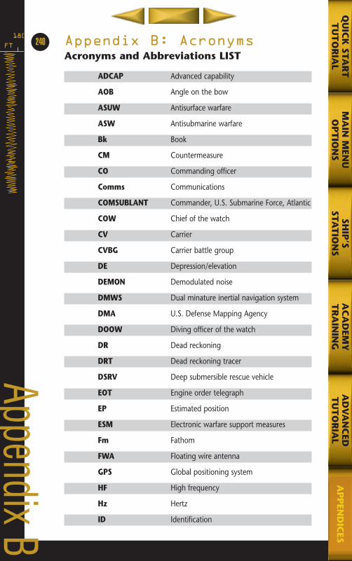
FT
180Appendix B: AcronymsAcronyms and Abbreviations LIST
ADCAP Advanced capability
AOB Angle on the bow
ASUW Antisurface warfare
ASW Antisubmarine warfare
Bk Book
CM Countermeasure
CO Commanding officer
Comms Communications
COMSUBLANT Commander, U.S. Submarine Force, Atlantic
COW Chief of the watch
CV Carrier
CVBG Carrier battle group
DE Depression/elevation
DEMON Demodulated noise
DMWS Dual minature inertial navigation system
DMA U.S. Defense Mapping Agency
DOOW Diving officer of the watch
DR Dead reckoning
DRT Dead reckoning tracer
DSRV Deep submersible rescue vehicle
EOT Engine order telegraph
EP Estimated position
ESM Electronic warfare support measures
Fm Fathom
FWA Floating wire antenna
GPS Global positioning system
HF High frequency
Hz Hertz
ID Identification
240
Appendix B
MA
IN M
ENU
OP
TIO
NS
AD
VA
NC
EDT
UT
OR
IAL
QU
ICK
STAR
TT
UT
OR
IAL
SHIP
’SSTA
TIO
NS
AC
AD
EMY
TR
AIN
ING
AP
PEN
DIC
ES
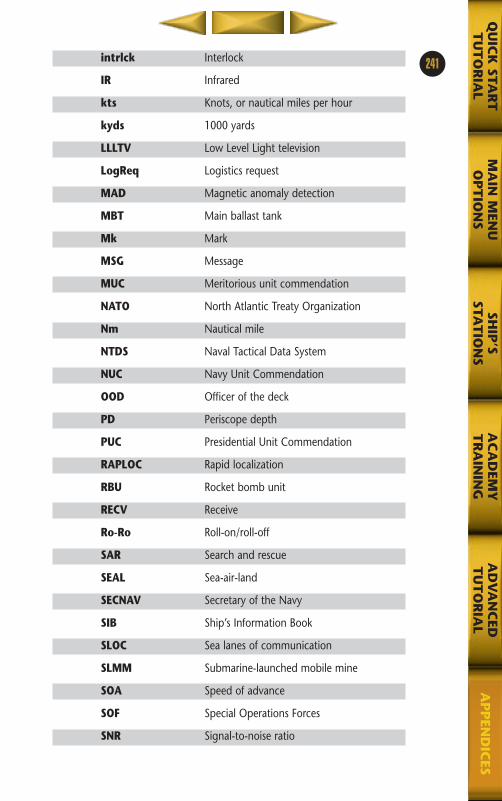
intrlck Interlock
IR Infrared
kts Knots, or nautical miles per hour
kyds 1000 yards
LLLTV Low Level Light television
LogReq Logistics request
MAD Magnetic anomaly detection
MBT Main ballast tank
Mk Mark
MSG Message
MUC Meritorious unit commendation
NATO North Atlantic Treaty Organization
Nm Nautical mile
NTDS Naval Tactical Data System
NUC Navy Unit Commendation
OOD Officer of the deck
PD Periscope depth
PUC Presidential Unit Commendation
RAPLOC Rapid localization
RBU Rocket bomb unit
RECV Receive
Ro-Ro Roll-on/roll-off
SAR Search and rescue
SEAL Sea-air-land
SECNAV Secretary of the Navy
SIB Ship’s Information Book
SLOC Sea lanes of communication
SLMM Submarine-launched mobile mine
SOA Speed of advance
SOF Special Operations Forces
SNR Signal-to-noise ratio
241
MA
IN M
ENU
OP
TIO
NS
AD
VA
NC
EDT
UT
OR
IAL
QU
ICK
STAR
TT
UT
OR
IAL
SHIP
’SSTA
TIO
NS
AC
AD
EMY
TR
AIN
ING
AP
PEN
DIC
ES
1
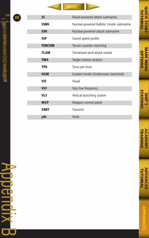
SS Diesel-powered attack submarine
SSBN Nuclear-powered ballistic missile submarine
SSN Nuclear-powered attack submarine
SSP Sound speed profile
TERCOM Terrain counter matching
TLAM Tomahawk land attack missile
TMA Target motion analysis
TPK Turns per knot
UGM Guided missile (Underwater launched)
VIS Visual
VLF Very low frequency
VLS Vertical launching system
WCP Weapon control panel
XMIT Transmit
yds Yards
FT
18064
Appendix B
MA
IN M
ENU
OP
TIO
NS
AD
VA
NC
EDT
UT
OR
IAL
QU
ICK
STAR
TT
UT
OR
IAL
SHIP
’SSTA
TIO
NS
AC
AD
EMY
TR
AIN
ING
AP
PEN
DIC
ES
242
MA
IN M
ENU
OP
TIO
NS
AD
VA
NC
EDT
UT
OR
IAL
QU
ICK
STAR
TT
UT
OR
IAL
SHIP
’S STA
TIO
NS
AC
AD
EMY
TR
AIN
ING
AP
PEN
DIC
ES
688(i)/AttackSubApxC,D,E,F 5/6/98 3:55 PM Page 7
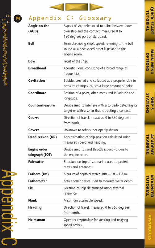
Appendix C: GlossaryAngle on the Aspect of ship referenced to a line between bow(AOB) own ship and the contact, measured 0 to
180 degrees port or starboard.
Bell Term describing ship’s speed, referring to the bell sound as a new speed order is passed to the engine room.
Bow Front of the ship.
Broadband Acoustic signal consisting of a broad range offrequencies.
Cavitation Bubbles created and collapsed at a propeller due to pressure changes; causes a large amount of noise.
Coordinate Position of a point, often measured in latitude and longitude.
Countermeasure Device used to interfere with a torpedo detecting itstarget or with a sonar that is tracking a contact.
Course Direction of travel, measured 0 to 360 degrees from north.
Covert Unknown to others; not openly shown.
Dead reckon (DR) Approximation of ship position calculated using measured speed and heading.
Engine order Device used to send throttle (speed) orders totelegraph (EOT) the engine room.
Fairwater Structure on top of submarine used to protect masts and antennas.
Fathom (fm) Measure of depth of water; 1fm = 6 ft = 1.8 m.
Fathometer Active sonar device used to measure water depth.
Fix Location of ship determined using external reference.
Flank Maximum attainable speed.
Heading Direction of travel, measured 0 to 360 degrees from north.
Helmsman Operator responsible for steering and relayingspeed orders.
FT
18064
Appendix C
MA
IN M
ENU
OP
TIO
NS
AD
VA
NC
EDT
UT
OR
IAL
QU
ICK
STAR
TT
UT
OR
IAL
SHIP
’SSTA
TIO
NS
AC
AD
EMY
TR
AIN
ING
AP
PEN
DIC
ES
244
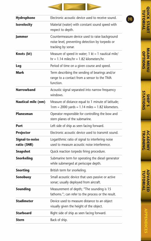
Hydrophone Electronic acoustic device used to receive sound.
Isovelocity Material (water) with constant sound speed with respect to depth.
Jammer Countermeasure device used to raise background noise level, preventing detection by torpedo or tracking by sonar.
Knots (kt) Measure of speed in water; 1 kt = 1 nautical mile/hr = 1.14 miles/hr = 1.82 kilometers/hr.
Leg Period of time on a given course and speed.
Mark Term describing the sending of bearings and/or range to a contact from a sensor to the TMA function.
Narrowband Acoustic signal separated into narrow frequency windows.
Nautical mile (nm) Measure of distance equal to 1 minute of latitude;1nm = 2000 yards = 1.14 miles = 1.82 kilometers.
Planesman Operator responsible for controlling the bow and stern planes of the submarine.
Port Left side of ship as seen facing forward.
Projector Electronic acoustic device used to transmit sound.
Signal-to-noise Logarithmic ratio of signal to interfering noiseratio (SNR) used to measure acoustic noise interference.
Snapshot Quick reaction torpedo firing procedure.
Snorkeling Submarine term for operating the diesel generator while submerged at periscope depth.
Snorting British term for snorkeling.
Sonobuoy Small acoustic device that uses passive or active sonar; usually deployed from aircraft.
Sounding Measurement of depth; “The sounding is 15 fathoms.”; can refer to the process or the result.
Stadimeter Device used to measure distance to an objectvisually given the height of the object.
Starboard Right side of ship as seen facing forward.
Stern Back of ship.
245
MA
IN M
ENU
OP
TIO
NS
AD
VA
NC
EDT
UT
OR
IAL
QU
ICK
STAR
TT
UT
OR
IAL
SHIP
’SSTA
TIO
NS
AC
AD
EMY
TR
AIN
ING
AP
PEN
DIC
ES
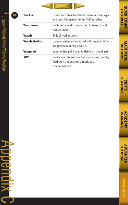
Tracker Device used to automatically follow a sonar signal and send information to the TMA function.
Transducer Electronic acoustic device used to transmit and receive sound.
Watch Shift of work rotation.
Watch station Location where an individual will conduct his/her assigned task during a watch.
Waypoint Intermediate point used to define an overall path.
XBT Device used to measure the sound speed profile, fired from a submarine similarly to a countermeasure.
FT
18064
Appendix C
MA
IN M
ENU
OP
TIO
NS
AD
VA
NC
EDT
UT
OR
IAL
QU
ICK
STAR
TT
UT
OR
IAL
SHIP
’SSTA
TIO
NS
AC
AD
EMY
TR
AIN
ING
AP
PEN
DIC
ES
246
MA
IN M
ENU
OP
TIO
NS
AD
VA
NC
EDT
UT
OR
IAL
QU
ICK
STAR
TT
UT
OR
IAL
SHIP
’S STA
TIO
NS
AC
AD
EMY
TR
AIN
ING
AP
PEN
DIC
ES
688(i)/AttackSubApxC,D,E,F 5/6/98 3:55 PM Page 11

Appendix D: BibliographyJane’s Major Warships 1997, vol. 1, David Miller ed., Jane’s InformationGroup Limited, London, 1997.
Terry Jones, Captain, USN (ret), former commanding officer SSN and SSB(N).
Kaufman, Steve. Silent Chase. Thomasson-Grant, Inc., Charlottesville, Virginia(1989).
Kaufman, Yogi; Stillwell, Paul. Sharks of Steel. Naval Institute Press, Annapolis,Maryland (1993).
Lightbody, Andy; Poyer, Joe. Submarines: Hunter/Killers and Boomers. BeekmanHouse, New York (1990).
The creative team at Sonalyst.
FT
180248
Appendix D
MA
IN M
ENU
OP
TIO
NS
AD
VA
NC
EDT
UT
OR
IAL
QU
ICK
STAR
TT
UT
OR
IAL
SHIP
’SSTA
TIO
NS
AC
AD
EMY
TR
AIN
ING
AP
PEN
DIC
ES