Embed Size (px)
Citation preview
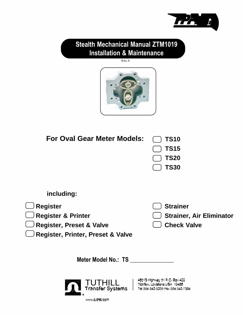
For Oval Gear Meter Models:
Stealth Mechanical Manual ZTM1019Installation & Maintenance
including:
TS10TS15TS20TS30
Meter Model No.: TS _______________
TUTHILL
Register StrainerRegister & Printer Strainer, Air EliminatorRegister, Preset & Valve Check ValveRegister, Printer, Preset & Valve

Table of Contents
FPP Meters and Principle of Operation ........................................ 1
Safety Instructions ......................................................................... 2
Installation and Operation Procedures .......................................... 2
Reversing the Meter Registration ................................................. 3
Adjusting the Calibrator................................................................. 4
Servicing the Meter ........................................................................ 5
Disassembling the Meter ............................................................... 7
Reassembling the Meter ................................................................ 9
Dimensional Drawing of Meter Purchased ...................................11
Meter Parts List & Torque Chart ................................................ . 12
Exploded Parts View ..................................................................... 13
Options/Accessories Parts Lists.................................................... 14
Warranty
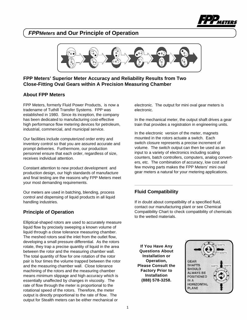
FPP Meters’ Superior Meter Accuracy and Reliability Results from TwoClose-Fitting Oval Gears within A Precision Measuring Chamber
About FPP Meters
FPP Meters, formerly Fluid Power Products, is now atradename of Tuthill Transfer Systems. FPP wasestablished in 1980. Since its inception, the companyhas been dedicated to manufacturing cost-effectivehigh performance flow metering devices for petroleum,industrial, commercial, and municipal service.
Our facilities include computerized order entry andinventory control so that you are assured accurate andprompt deliveries. Furthermore, our productionpersonnel ensure that each order, regardless of size,receives individual attention.
Constant attention to new product development andproduction design, our high standards of manufactureand final testing are the reasons why FPP Meters meetyour most demanding requirements.
Our meters are used in batching, blending, processcontrol and dispensing of liquid products in all liquidhandling industries.
Principle of Operation
Elliptical-shaped rotors are used to accurately measureliquid flow by precisely sweeping a known volume ofliquid through a close tolerance measuring chamber.The meshed rotors seal the inlet from the outlet flow,developing a small pressure differential. As the rotorsrotate, they trap a precise quantity of liquid in the areabetween the rotor and the measuring chamber wall.The total quantity of flow for one rotation of the rotorpair is four times the volume trapped between the rotorand the measuring chamber wall. Close tolerancemachining of the rotors and the measuring chambermeans minimum slippage and high accuracy which isessentially unaffected by changes in viscosity. Therate of flow through the meter is proportional to therotational speed of the rotors. Therefore, the meteroutput is directly proportional to the rate of flow. Theoutput for Stealth meters can be either mechanical or
In the electronic version of the meter, magnetsmounted in the rotors actuate a switch. Eachswitch closure represents a precise increment ofvolume. The switch output can then be used as aninput to a variety of electronics including scalingcounters, batch controllers, computers, analog convert-ers, etc. The combination of accuracy, low cost andfew moving parts makes the FPP Meters’ mini ovalgear meters a natural for your metering applications.
Fluid Compatibility
If in doubt about compatibility of a specified fluid,contact our manufacturing plant or see ChemicalCompatibility Chart to check compatibility of chemicalsto the wetted materials.
FPP Meters and Principle of OperationFPPMeters and Our Principle of Operation
If You Have AnyQuestions About
Installation orOperation,
Please Consult theFactory Prior to
Installation(888) 578-3258.
SHAFTS
SHAFTS
SHAFTS SHAFTS
electronic. The output for mini oval gear meters iselectronic.
In the mechanical meter, the output shaft drives a geartrain that provides a registration in engineering units.
1

Installation & Operation
Make sure that all necessary safety precautionshave been taken including proper clothing,personal safety equipment and fire safetyequipment if required.
Before Start-up of Meter Make Certain:1. The meter is properly mounted, secured and
piped.2. All connections are tight.3. All bleed and drain valves are closed.4. Do NOT smoke near meter or use meter near an open flame when metering flammable fluids. Fire could result.5. This meter is not intended for use with fluids for human consumption.
Install the Meter and Accessories inCompliance with All Applicable Local, State andFederal Construction, Electrical and SafetyCodes.
InstallationPositive displacement meters are designed to operate full ofliquid. The meter should be installed in a manner such thatit remains full of liquid at all times.
Protective caps installed in each meter at the time ofshipment should remain in the openings until you are readyto install in the piping system.
Prior to meter installation, the piping system should beflushed to remove all debris. Apply pipe compound to themale threads, to install the companion flanges.
Install the companion flanges. Tighten to a position thatallows the meter to bolt to the companion flanges, freeof pipe stress. The meter should always be supportedby bolting to a platform. Never use the connecting pipeas the means of support.
When installing the meter consider future maintenance, andinstall in the best location available to facilitate future metermaintenance. The meter can be disassembled and servicedin place, and provisions for service should be consideredduring installation.
For the best accuracy, install the meter so that the gearshafts are positioned in a horizontal plane, rotating withoutthe weight of the gear resting on the body or cover of themeter as shown on page 1. In critical installations blockvalves and by-pass lines are recommended. This allows themeter to be serviced without interruption of flow in criticalprocess application.
SAFETY INSTRUCTIONS
It is recommended that a strainer be installedupstream of each meter to prevent damage from foreignmatter, such as weld slag, pipe scale, etc.
Calibration means should be provided during installation. Aneasy means for diverting flow into a calibration vessel shouldbe considered.
Hydraulic shock like thermal expansion can be harmful tometer components. Consideration should be given todesigning pumping piping systems to eliminate hydraulicshock.
OperationFill the system slowly to avoid operation on air or vapor. Thiscan be accomplished in the following manner:
1. Throttle the meter inlet valve, and allow to fill slowly bygravity.
2. Crack open the outlet valve, start the pump, then slowlycrack open the inlet valve and fill the meter slowlybefore fully opening the inlet and outlet valves.
The meter is not designed to operate on air, but the designand materials of construction allow for operation on vapor forshort periods of time without damage to the elliptical gears ormeter internals.
Note: Over-speed and hammer caused by the presenceof vapor in the system can cause internal damage to themeter.
Operating the meter in excess of its maximum design flowcan cause excessive wear or premature failure. However,the meter can be calibrated to operate below the minimumdesign flow rate as indicated on the meter name plate if theflow remains constant, or the product is viscous.
Thermal relief valves are recommended and should beinstalled whenever it is possible to block the meterbetween two valves. Thermal pressures many times theoperating pressure are possible with only a small rise intemperature.
The meter’s non-shock Maximum OperatingPressure is indicated on the meter name plate.The meter should never be operated in excess ofthis pressure. Care should be taken to eliminatethermal and hydraulic shock pressures so thatthey do not exceed the meter’s MaximumWorking Pressure design.
SAFETY INSTRUCTIONS
2
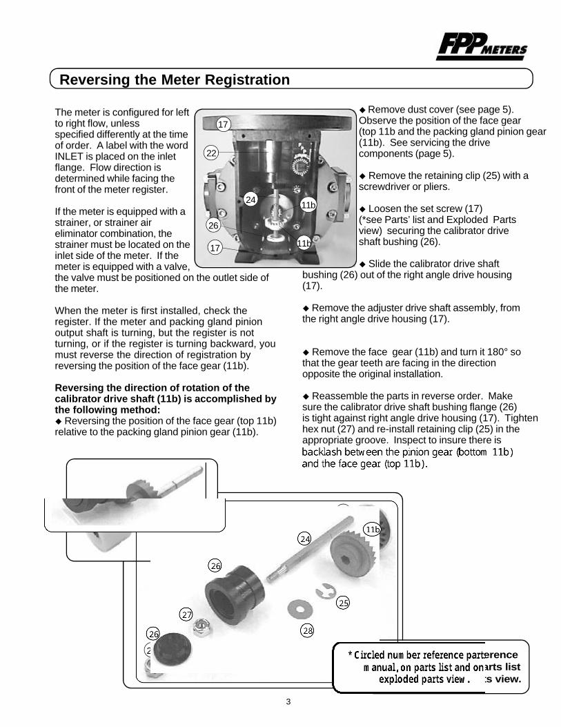
The meter is configured for leftto right flow, unlessspecified differently at the timeof order. A label with the wordINLET is placed on the inletflange. Flow direction isdetermined while facing thefront of the meter register.
If the meter is equipped with astrainer, or strainer aireliminator combination, thestrainer must be located on theinlet side of the meter. If themeter is equipped with a valve,the valve must be positioned on the outlet side ofthe meter.
When the meter is first installed, check theregister. If the meter and packing gland pinionoutput shaft is turning, but the register is notturning, or if the register is turning backward, youmust reverse the direction of registration byreversing the position of the face gear (11b).
Reversing the direction of rotation of thecalibrator drive shaft (11b) is accomplished bythe following method:u Reversing the position of the face gear (top 11b)relative to the packing gland pinion gear (11b).
u Remove dust cover (see page 5).Observe the position of the face gear(top 11b and the packing gland pinion gear(11b). See servicing the drivecomponents (page 5).
u Remove the retaining clip (25) with ascrewdriver or pliers.
u Loosen the set screw (17)(*see Parts’ list and Exploded Partsview) securing the calibrator driveshaft bushing (26).
u Slide the calibrator drive shaftbushing (26) out of the right angle drive housing(17).
u Remove the adjuster drive shaft assembly, fromthe right angle drive housing (17).
u Remove the face gear (11b) and turn it 180° sothat the gear teeth are facing in the directionopposite the original installation.
u Reassemble the parts in reverse order. Makesure the calibrator drive shaft bushing flange (26)is tight against right angle drive housing (17). Tightenhex nut (27) and re-install retaining clip (25) in theappropriate groove. Inspect to insure there is
Reversing the Meter Registration
3
* Circled numbers referenceparts in manual, on parts listand on exploded parts view.
17
24
22
11b
11b
26
26
2728
25
24
11b
17

Adjusting the Calibrator
Meters equipped with mechanical registers mayhave a mechanical calibrator. If so, the calibratorcan be used to easily adjust the meter output sothat the mechanical registration matches preciselythe volume delivered to a meter prover:
u Remove the dust cover (18), see page 5.
u Check the meter registration by delivering aknown volume of product into an accurate prover.Perform several tests to verify the meterrepeatability.
u Record the meter reading determined in theabove step.
u Note the volume in the prover.
u When the prover volume is less than the meterregister, add the percentage to the originalcalibrator setting by turning the knob in thedirection of the arrow marked “+ volume” on thecalibrator. Each click on the calibrator representsa .03% increment.
u When the prover volume is more than themeter register volume, subtract the percentagefrom the original calibrator setting by turning theknob in the direction of the arrow marked “-volume” on the calibrator.
u Make several prover runs to check meteraccuracy and repeatability.
Each click of the calibrator represents a .03%increment. There are two clicks per division onthe adjustment dial. Run product through themeter to allow the calibrator to adjust to the newsetting.
% CORRECTION = X 100 (Vol. in the Prover)
(Vol. in the Prover) - (Vol. on the Meter Register)
4

Avoid pipe strain and stress when making meterrepairs. The weight of the piping and the metershould be supported independently. This meansthat the meter can be serviced without affectingthe piping alignment.
Avoid prying or exerting heavy pressure onprecision parts as this could affect theperformance of the meter.
Assure all machined parts are free of burs andnicks. Stone all machined surfaces if necessaryto remove burs.
Always coat bolt threads with an anti-seize or anappropriate lubricant to prevent thread damageand to assure proper torque values are appliedwhen reassembling.
If meter threads are damaged, repair usinginserts.
Note: The calibrator (22) may be removed fromthe calibrator housing without removing theadapter flange (17) by first removing the adjusterdrive shaft assembly.
Servicing the Meter
uRemoving the adjuster drive shaft assembly:(Refer to the numbered pictures on page 3)1. Loosen the set screw (17) located in thecalibrator housing base, using an Allen wrench(see Torque and Wrench Chart on 12.)2. Remove the retaining clip (25) using ascrewdriver or pliers.3. Slide the calibrator drive shaft bushing (26 andcalibrator drive shaft (24) out of the right angledrive housing (17).4. Reinstall in the reverse procedure.
5
Servicing the Drive Components
u Removing the dust cover:1. Remove hex head screws (19) and (20). Thesehex head screws require a 5/16 socket.
u Replacing theadjuster:1. Remove thecalibrator driveshaft assembly(see page 5.)2. Remove thecounter from thetop of the V/Radapter flange(17).3. Remove thetwo screws (23)attaching thecalibrator to thecounter adapterflange usingPhillips screwdriver.4. Reverse the procedure to reinstall the newcalibrator.
18
19
20
17
17
22
1717
22 17
17
17
19
17
23 23
2020
17
SAFETY INSTRUCTIONS
SAFETY INSTRUCTIONS
The wrenches required for each step, and thetorque specification for each screw or bolt isshown in the Torque and Wrench Chart on thebottom of page 12. Anti-seize or an equivalentlubricant should be applied to each bolt or screwbefore it is installed to assure proper torqueapplication and ease of assembly anddisassembly.
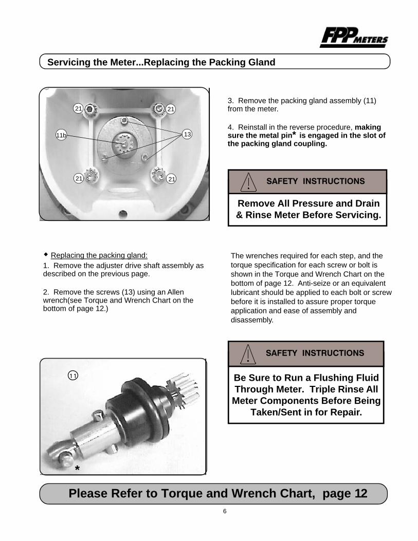
w Replacing the packing gland:1. Remove the adjuster drive shaft assembly asdescribed on the previous page.
2. Remove the screws (13) using an Allenwrench(see Torque and Wrench Chart on thebottom of page 12.)
Please Refer to Torque and Wrench Chart, page 126
Servicing the Meter...Replacing the Packing Gland
11 Be Sure to Run a Flushing FluidThrough Meter. Triple Rinse All
Meter Components Before BeingTaken/Sent in for Repair.
Remove All Pressure and Drain& Rinse Meter Before Servicing.
*
3. Remove the packing gland assembly (11)from the meter.
4. Reinstall in the reverse procedure, makingsure the metal pin* is engaged in the slot ofthe packing gland coupling.
21
21
21
21
11b 13
Disassembling the Meter
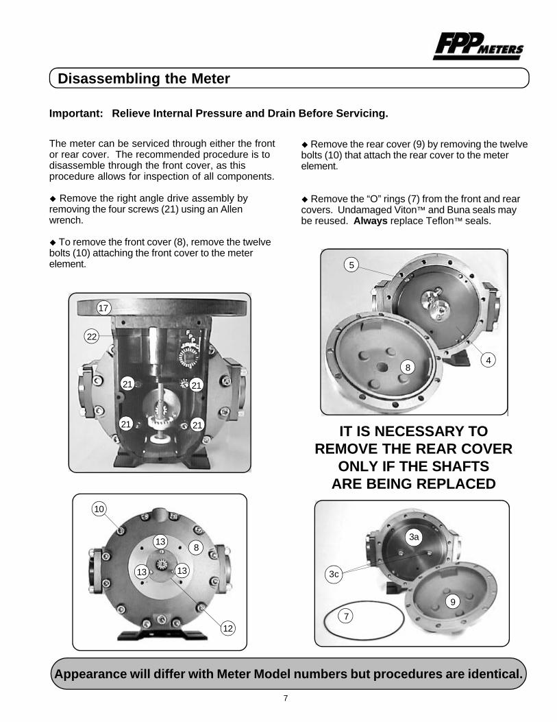
The meter can be serviced through either the frontor rear cover. The recommended procedure is todisassemble through the front cover, as thisprocedure allows for inspection of all components.
u Remove the right angle drive assembly byremoving the four screws (21) using an Allenwrench.
u To remove the front cover (8), remove the twelvebolts (10) attaching the front cover to the meterelement.
Important: Relieve Internal Pressure and Drain Before Servicing.
u Remove the rear cover (9) by removing the twelvebolts (10) that attach the rear cover to the meterelement.
u Remove the “O” rings (7) from the front and rearcovers. Undamaged Viton™ and Buna seals maybe reused. Always replace Teflon™ seals.
IT IS NECESSARY TOREMOVE THE REAR COVER
ONLY IF THE SHAFTSARE BEING REPLACED
Appearance will differ with Meter Model numbers but procedures are identical.
7
8
10
3a
12
13
9
7
3c
84
13
13
5
17
21
22
21
2121

u Remove the screws (6) from the gear plate (4a)by using an Allen wrench.
u Remove the post plate assembly (3) ifnecessary. Using an Allen wrench, remove thescrews attaching the post plate to the meter body.Remove the post plate using jack bolt, ifnecessary.
u To maintain the meters maximum accuracy it isrecommended that the post plate with post bereplaced as an assembly. It is possible to removeand to replace the old bearing post, which requiresa press, and could result in loss of accuracy.
u Remove the gear plate (4) assembly from themeter body, using a 5/16 X 18 X 1” jack bolt, ifnecessary. Once the gear plate is removed,remove the gears (2) and inspect them for wearand damage. If replacement is required, see thenext section on servicing the gear and post plates.measuring chamber.
Inspection and Repair
u Inspect and repair all critical surfaces like gearteeth, oval gears, gear and post plates andinternal housing. Remove any deposits using afine emery cloth or fine wire brush. Be careful notto score or damage any of the internal parts.Changing the shape, or damaging in any waymay interfere with the operation of the meter.Remove all particulate, or grit, as this may alsointerfere with the proper operation of the meter.
u Replace all worn or damaged parts. The properoperation of the meter requires close tolerancesto be maintained within the meter chamber. Thegears must rotate freely within the measuringchamber without rub or excess clearance.
Disassembling the Meter continued...
8
Front view,post plate
Rear view,post plate
6
6
3a
6
6
3b 3b
3a3c
4
8
6
4a
2
4a
3a
3b
3b
3c3c3d 3d
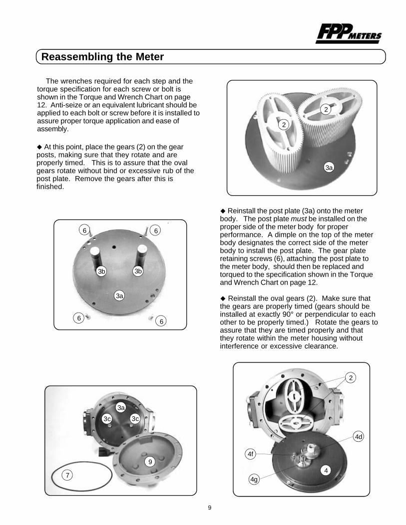
Reassembling the Meter
The wrenches required for each step and thetorque specification for each screw or bolt isshown in the Torque and Wrench Chart on page12. Anti-seize or an equivalent lubricant should beapplied to each bolt or screw before it is installed toassure proper torque application and ease ofassembly.
u At this point, place the gears (2) on the gearposts, making sure that they rotate and areproperly timed. This is to assure that the ovalgears rotate without bind or excessive rub of thepost plate. Remove the gears after this isfinished.
u Reinstall the post plate (3a) onto the meterbody. The post plate must be installed on theproper side of the meter body for properperformance. A dimple on the top of the meterbody designates the correct side of the meterbody to install the post plate. The gear plateretaining screws (6), attaching the post plate tothe meter body, should then be replaced andtorqued to the specification shown in the Torqueand Wrench Chart on page 12.
u Reinstall the oval gears (2). Make sure thatthe gears are properly timed (gears should beinstalled at exactly 90° or perpendicular to eachother to be properly timed.) Rotate the gears toassure that they are timed properly and thatthey rotate within the meter housing withoutinterference or excessive clearance.
9
6
6
3a
6
6
3b 3b
9
7
3a
3c 3c
4
2
3a
2
2
4d
4g
4f

u Reinstall the rear cover (9) and “O” ring (7). Besure the drain plug (31) is toward the bottom of themeter. The twelve bolts should be torqued tospecification shown in the Torque & Wrench Charton page 12.
u Reinstall the gear plate (4a) onto the meterbody. The pressure equalizing hole should benear the outlet flange and the pinion gear (4f)should be located near the top of the meter.Tighten the screws (6), attaching the gear plate tothe meter body, torqued to the specificationshown in the Torque and Wrench Chart on page12.
u At this point, rotate the drive gear (4d) assuringthat all gears turn freely and that the oval gears (2)turn freely in the meter chamber.
u Reinstall the "O" (7) ring on the front cover (8)and then place the front cover back onto the meter.Be sure the drain plug is toward the bottom of thecover. This facilitates draining the meter andpositions the cover to accept the calibrator adapter.The twelve bolts should be torqued to the specifi-cation shown on the Torque and Wrench Chart onpage 12.
u Reinstall the right angle drive housing (17). Thescrews (21) should be torqued to the specificationshown in the chart on page 12.
Please Refer to Torque and Wrench Chart (page 12)
Reassembling the Meter continued...
10
9
3a
78
4
4g
2
4
2
21 21
2121
1311b
12
4f
4d

12*
33a**3b**3c**3d**44a***4b***4c***4d***4e***4f***4g***4h***4i***567*8910
11*11a11b11c11d1213141516171819202121a21b21c21d222324252627
1111111122211121111114821124
1111113112241211111121222
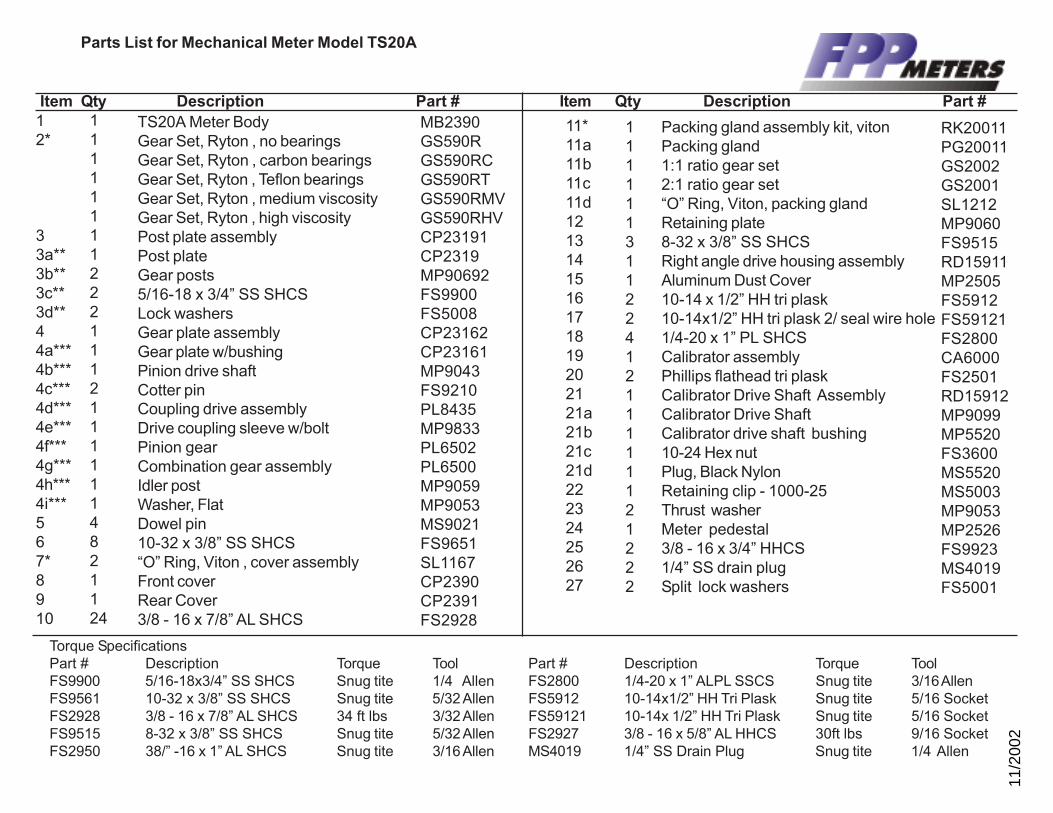
TS20A Meter BodyGear Set, Ryton , no bearingsGear Set, Ryton , carbon bearingsGear Set, Ryton , Teflon bearingsGear Set, Ryton , medium viscosityGear Set, Ryton , high viscosityPost plate assemblyPost plateGear posts5/16-18 x 3/4” SS SHCSLock washersGear plate assemblyGear plate w/bushingPinion drive shaftCotter pinCoupling drive assemblyDrive coupling sleeve w/boltPinion gearCombination gear assemblyIdler postWasher, FlatDowel pin10-32 x 3/8” SS SHCS“O” Ring, Viton , cover assemblyFront coverRear Cover3/8 - 16 x 7/8” AL SHCS
MB2390GS590RGS590RCGS590RTGS590RMVGS590RHVCP23191CP2319MP90692FS9900FS5008CP23162CP23161MP9043FS9210PL8435MP9833PL6502PL6500MP9059MP9053MS9021FS9651SL1167CP2390CP2391FS2928
Packing gland assembly kit, vitonPacking gland1:1 ratio gear set2:1 ratio gear set“O” Ring, Viton, packing glandRetaining plate8-32 x 3/8” SS SHCSRight angle drive housing assemblyAluminum Dust Cover10-14 x 1/2” HH tri plask10-14x1/2” HH tri plask 2/ seal wire hole1/4-20 x 1” PL SHCSCalibrator assemblyPhillips flathead tri plaskCalibrator Drive Shaft AssemblyCalibrator Drive ShaftCalibrator drive shaft bushing10-24 Hex nutPlug, Black NylonRetaining clip - 1000-25Thrust washerMeter pedestal3/8 - 16 x 3/4” HHCS1/4” SS drain plugSplit lock washers
RK20011PG20011GS2002GS2001SL1212MP9060FS9515RD15911MP2505FS5912FS59121FS2800CA6000FS2501RD15912MP9099MP5520FS3600MS5520MS5003MP9053MP2526FS9923MS4019FS5001
Item Qty Description Part # Item Qty Description Part #
Torque SpecificationsPart # Description Torque Tool Part # Description Torque ToolFS9900 5/16-18x3/4” SS SHCS Snug tite 1/4 Allen FS2800 1/4-20 x 1” ALPL SSCS Snug tite 3/16 AllenFS9561 10-32 x 3/8” SS SHCS Snug tite 5/32 Allen FS5912 10-14x1/2” HH Tri Plask Snug tite 5/16 SocketFS2928 3/8 - 16 x 7/8” AL SHCS 34 ft lbs 3/32 Allen FS59121 10-14x 1/2” HH Tri Plask Snug tite 5/16 SocketFS9515 8-32 x 3/8” SS SHCS Snug tite 5/32 Allen FS2927 3/8 - 16 x 5/8” AL HHCS 30ft lbs 9/16 SocketFS2950 38/” -16 x 1” AL SHCS Snug tite 3/16 Allen MS4019 1/4” SS Drain Plug Snug tite 1/4 Allen
Parts List for Mechanical Meter Model TS20A
11/2
002

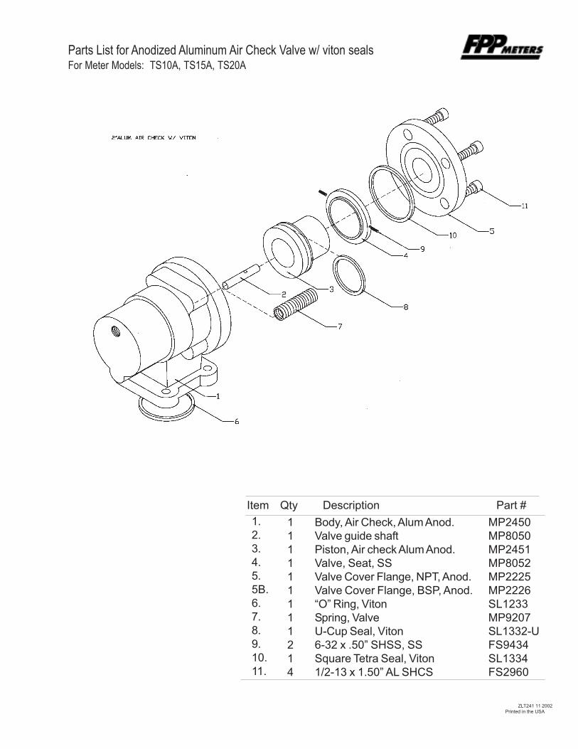
Parts List for Anodized Aluminum Air Check Valve w/ viton sealsFor Meter Models: TS10A, TS15A, TS20A
ZLT241 11 2002Printed in the USA
1.2.3.4.5.5B.6.7.8.9.10.11.
111111111214
Body, Air Check, Alum Anod.Valve guide shaftPiston, Air check Alum Anod.Valve, Seat, SSValve Cover Flange, NPT, Anod.Valve Cover Flange, BSP, Anod.“O” Ring, VitonSpring, ValveU-Cup Seal, Viton6-32 x .50” SHSS, SSSquare Tetra Seal, Viton1/2-13 x 1.50” AL SHCS
MP2450MP8050MP2451MP8052MP2225MP2226SL1233MP9207SL1332-UFS9434SL1334FS2960
Item Qty Description Part #
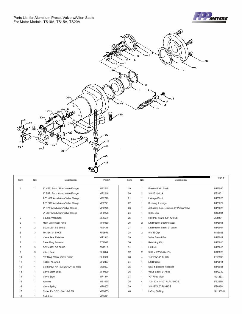
Parts List for Aluminum Preset Valve w/Viton Seals For Meter Models: TS10A, TS15A, TS20A
Item
1
2
3
4
5
6
7
8
9
10
11
12
13
14
15
16
17
18
Part # Qty Description Part # Item Qty Description
1 1" NPT, Anod. Alum Valve Flange MP2215 19 1 Present Link, Shaft MP3050
1" BSP, Anod Alum, Valve Flange MP2216 20 2 3/8-16 Ny-Lok FS3901
1.5" NPT Anod Alum Valve Flange MP2220 21 1 Linkage Pivot MP8025
1.5" BSP Anod Alum Valve Flange MP2221 22 1 Bushing, Linkage MP8027
2" NPT Anod Alum Valve Flange MP2225 23 1 Actuating Arm, Linkage, 2" Piston Valve MP8026
2" BSP Anod Alum Valve Flange MP2226 24 1 3/8 E-Clip MS0001
1 Square Viton Seal SL1334 25 1 Roll Pin, 5/32 x 5/8" 420 SS MS8001
1 Main Valve Seat Ring MP8030 26 2 Lift Bracket Bushing Assy MP3051
2 6-32 x .50" SS SHSS FS9434 27 1 Lift Bracket Shaft, 2" Valve MP3054
3 10-32x1.0" SHCS FS9659 28 2 5/8" E-Clip MS5023
1 Valve Seat Retainer MP2343 29 1 Valve Stem Lifter MP3012
1 Stem Ring Retainer ST9065 30 1 Retaining Clip MP3010
3 8-32x.375" SS SHCS FS9515 31 1 Lift Link MP3015
3 Viton, Seal SL1204 32 2 3/32 x 1/2" Cotter Pin MS3023
1 "O" Ring, Viton, Valve Piston SL1328 33 4 1/4"-20x1/2" SHCS FS2802
1 Piston, Al. Anod MP2337 34 1 Lift Bracket MP3011
1 Set Screw, 1/4 20x.25" w/.125 Hole MS8027 35 1 Seal & Bearing Retainer MP8031
1 Valve Stem Seat MP9920 36 1 Valve Body, 2" Anod MP2330
1 Valve Stem MP1344 37 1 "O" Ring, Viton SL1233
1 Washer MS1060 38 4 1/2 - 13 x 1-1/2" ALPL SHCS FS2960
1 Valve Spring MP9207 39 1 3/8-18X1.0" PLHHCS FS0920
1 Cotter Pin 3/32 x 3/4 18-8 SS MS9055 40 1 U-Cup O-Ring SL1332-U
1 Ball Joint MS3021

Item Qty Description Part #
1 1 1” NPT Andz. Al Valve Flange MP22151” BSPP Andz. Al Valve Flange MP22161½” NPT Andz. Al Valve Flange MP22201½” BSPP Andz. Al Valve Flange MP22212” NPT Andz. Al Valve Flange MP22252” BSPP Andz. Al Valve Flange MP2226
2 1 Square Tetra Seal SL23343 1 Main Valve Seat Ring MP80304 3 10-32 X 1” SHCS FS96595 1 Valve Stem Seat MP23406 1 TeflonTM Seal SL92017 1 Valve Stem Seat MP13418 1 Andz. Al Valve Piston MP23359 1 TeflonTM U-cup SL2230-U10 1 Retaining ring MS903611 4 1/2-13 X 1 1/2” ALPL SHCS FS296012 1 Ball Joint MS302113 1 Preset Link MP305014 1 Andz. Al Valve Body MP233015 1 Cotter Pin FS921016 1 .010 Washer MS5022
Item Qty Description Part #
17 1 Valve Stem MP134218 1 .016 Washer V11071-17119 1 Valve Spring MP920020 1 “O” Ring, TeflonTM SL223321 1 Retaining Clip MP301022 2 Cotter Pin MS302323 1 Lift Link MP301524 2 5/8 E-Clip MS502325 1 Lift Bracket MP301126 1 Actuating Arm Shaft MP305327 4 1/4-20 X 1/2” SHCS FS280228 2 1/8-3/8 Grooved Pin MS302029 2 “O” Ring, Chemraz SL2012-50530 1 Seal & Bearing Retainer MP8031-131 2 3/8-16 NY-LOK FS390132 1 Linkage Pivot MP803233 3 3/8 E-Clip MS000134 1 Lift Bracket Assy. MP305135 1 Actuating Arm Linkage MP301336 1 Pivot Pin MP803337 1 U-cup, TeflonTM SL2204-U
ZLT238 5/00Printed in the USA
Parts List for Aluminum Preset Valve w/TeflonTM SealsFor Meter Models: TS10A, TS15A, TS20A
Item Qty Description Part #
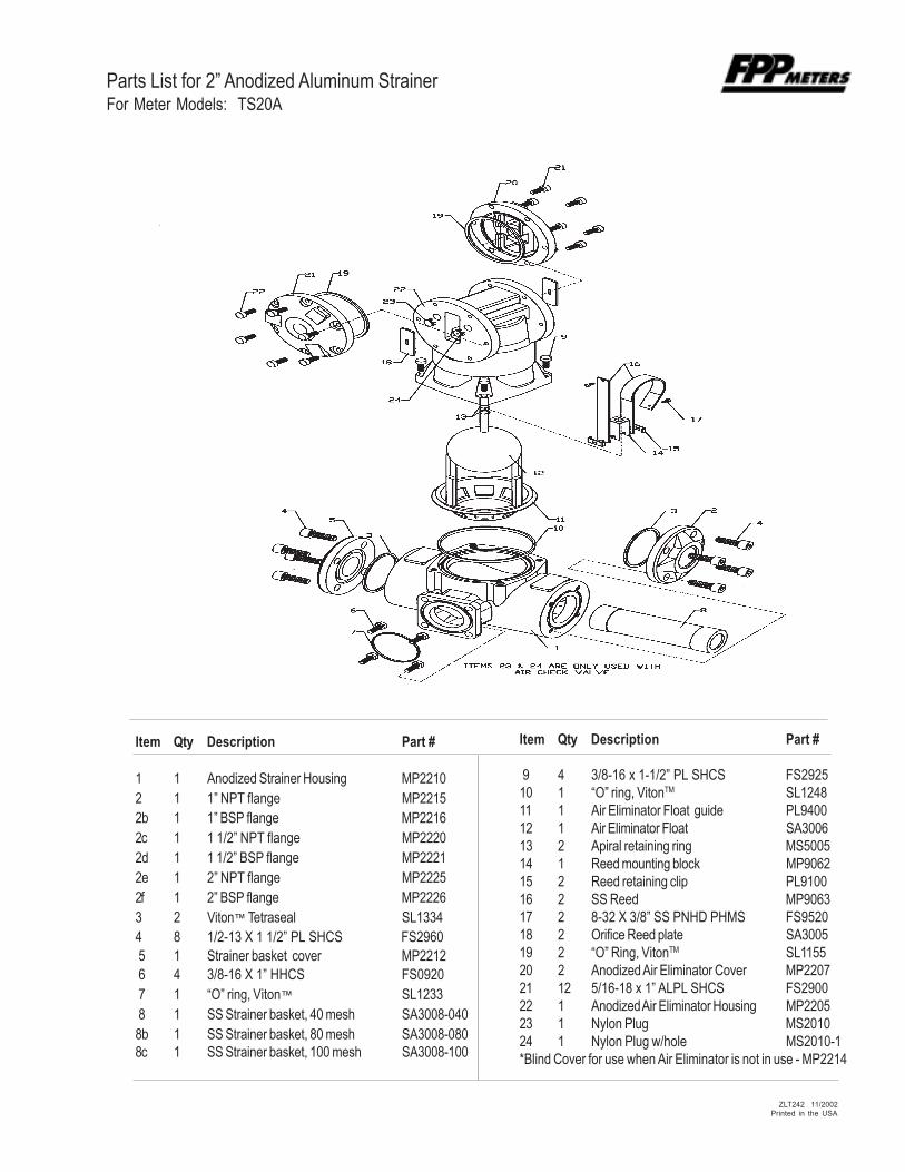
1 1 Anodized Strainer Housing MP22102 1 1” NPT flange MP22152b 1 1” BSP flange MP22162c 1 1 1/2” NPT flange MP22202d 1 1 1/2” BSP flange MP22212e 1 2” NPT flange MP22252f 1 2” BSP flange MP22263 2 Viton™ Tetraseal SL13344 8 1/2-13 X 1 1/2” PL SHCS FS2960 5 1 Strainer basket cover MP2212 6 4 3/8-16 X 1” HHCS FS0920 7 1 “O” ring, Viton™ SL1233 8 1 SS Strainer basket, 40 mesh SA3008-0408b 1 SS Strainer basket, 80 mesh SA3008-0808c 1 SS Strainer basket, 100 mesh SA3008-100
Item Qty Description Part #
9 4 3/8-16 x 1-1/2” PL SHCS FS292510 1 “O” ring, VitonTM SL124811 1 Air Eliminator Float guide PL940012 1 Air Eliminator Float SA300613 2 Apiral retaining ring MS500514 1 Reed mounting block MP906215 2 Reed retaining clip PL910016 2 SS Reed MP906317 2 8-32 X 3/8” SS PNHD PHMS FS952018 2 Orifice Reed plate SA300519 2 “O” Ring, VitonTM SL115520 2 Anodized Air Eliminator Cover MP220721 12 5/16-18 x 1” ALPL SHCS FS290022 1 Anodized Air Eliminator Housing MP220523 1 Nylon Plug MS201024 1 Nylon Plug w/hole MS2010-1*Blind Cover for use when Air Eliminator is not in use - MP2214
Parts List for 2” Anodized Aluminum StrainerFor Meter Models: TS20A
ZLT242 11/2002Printed in the USA

Warranty
Tuthill Transfer Systems (“Manufacturer”) warrants to each buyer ofits FPP Meters products (the “Buyer”) for a period of 12 months fromdate of invoice or sales receipt, but in no event more than 18 monthsfrom date of manufacture, that goods of its manufacture (“Goods”) willbe free from defects of material and workmanship. Manufacturer’ssole obligation under the foregoing warranties will be limited to either,at Manufacturers’ option, replacing or repairing defective Goods(subject to limitations hereinafter provided) or refunding the purchaseprice for such Goods theretofore paid by the Buyer, and Buyer’sexclusive remedy for breach of any such warranties will beenforcement of such obligations of Manufacturer. If Manufacturer sorequests the return of the Goods, the Goods will be redelivered toManufacturer in accordance with Manufacturer’s instructions F.O.B.Factory. The remedies contained herein shall constitute the solerecourse of the Buyer against Manufacturer for breach of warranty.IN NO EVENT SHALL MANUFACTURER'S LIABILITY ON ANY
Please have the following information available when you makeinquiries, order replacement parts, or schedule service:
Your meter’s serial number: _____________________________
Your meter’s model number: _____________________
Your full service Distributor: ________________________
Your full service Distributor’s phone number: _______________
CLAIM FOR DAMAGES ARISING OUT OF THE MANUFACTURESALE, DELIVERY OR USE OF THE GOODS EXCEED THEPURCHASE PRICE OF THE GOODS. The foregoing warranties willnot extend to Goods subjected to misuse, neglect, accident orimproper installation or maintenance, or which have been altered orrepaired by anyone other than Manufacturer or its authorizedrepresentative. THE FOREGOING WARRANTIES AREEXCLUSIVE AND IN LIEU OF ALL OTHER WARRANTIES OFMERCHANTABILITY, FITNESS FOR PURPOSE OF ANY OTHERTYPE, WHETHER EXPRESS OR IMPLIED. No person may vary theforegoing warranties and remedies except in writing signed by a dulyauthorized officer of Manufacturer. Warranties or remedies that differfrom the foregoing shall not otherwise be binding on Manufacturer.The Buyer’s acceptance of delivery of the Goods constitutesacceptance of the foregoing warranties and remedies, and allconditions and limitations thereof.