Embed Size (px)
Citation preview

11th North American Waste to Energy Conference Copyright � 2003 by ASME
NAWTEC11-1672
TURBOSORP@ - Emission limits after 17th BimSch V (German Federal Imission
Act) at lowest costs in a simple dry process - Comparison of dry/semi dry processes and results of mercury and dioxin separation in a one step process
H.K Reissner, C. Brunner, K Barntbaler
Austrian Energy and Environment AG Waagner-BirostrafJe 105, A-8021 Graz
Austria
Abstract: The TURBOSORP® -process is a dry flue gas cleaning process to remove certain pollutants like S02, HC1, Hg, heavy metals, dioxins and furans. The main principle of this process is to bring flue gas in an intensive contact with Ca(OH)z, open hearth furnace coke, water and recirculated material in the Turboreactor. The Turboreactor operates as circulating fluidized bed in the manner of fast fluidisation. The gas/solid mixture leaves the Turboreactor at the top and the solids are separated in a fabric filter from the flue gas. More than 99% of the separated solids are recirculated to the Turboreactor and the rest leaves the process as product. Due to the high sorbent recirculation percentage
a high sorbent utilization and low stoechiometric rates are reached in the TURBOSORP® -process. Due
to the fact to have plants in operation for the spray absorption and for the TURBOSORP® process, a
comparison definitely showed advantages for the TURBOSORP® process. Experiences of the plant start
up of a TURBOSORP® plant in Poland concerning optimisation in pressure loss and hydrodynamics of the Turboreactor using CFD-Simulation are presented. Results concerning mercury and dioxin
separation in our Turbosorp® pilot plant after the refuse incinerator MY Spittelau, Vienna, are discussed.
Introduction
Today the application of dry technologies for the cleaning of flue gases of power stations or waste incineration plants is considered as the state-of-the-art technology. Due to the use of the fluidized bed technology and of the recirculation of the partially reacted product it has been possible to eliminate prejudices against this technology which were based upon a bad utilisation of the sorbent and low separation performances. Because of the considerably reduced investment costs there is an important market potential for the dry technology in addition to the wet technology. Especially in the field of retrofitting and/or rehabilitation of existing plants the dry technology plays an important role.
Presently, various competitors offer dry processes on the market of which the differences in the process concept hardly can be made out. In certain cases, the differences only exist in the plant technology and in the design of the
65
reactor. Nevertheless, the potential of optumsation aiming at further improved desulphurisation performances and at minimum consumption of consumables is not exhausted yet. At the present state-of-the-art in this technology degrees of separation up to 95 % at Ca/S-ratios up to 1.25 can be achieved in the field of flue gas desulphurisation without problems. Even in the field of flue gas cleaning after waste incineration plants the emission limits as prescribed by the 17th Decree of the German Federal Immission Act (17. BImSch V) can be achieved (refer also to Table 1).
Austrian Energy and Environment (AEE), emerged from the traditional companies Waagner Biro AG and Simmering Graz Pauker AG, was reestablished in July 2002, after a short intermezzo with the Babcock Borsig Power Group between 1999 and 2002. By way of the TURBOSORP® process AEE offers a dry technology for the flue gas desulphurisation and the flue gas cleaning after waste incineration plants. Because of the use of the most up-to-date design tools like e.g. CFD-modelling of
critical plant components, AEE is able to provide a optimum design. Additionally AEE operates a pilot plant where critical operating cases, as for example extreme flue gas compositions can be simulated during experiments [1, 2].
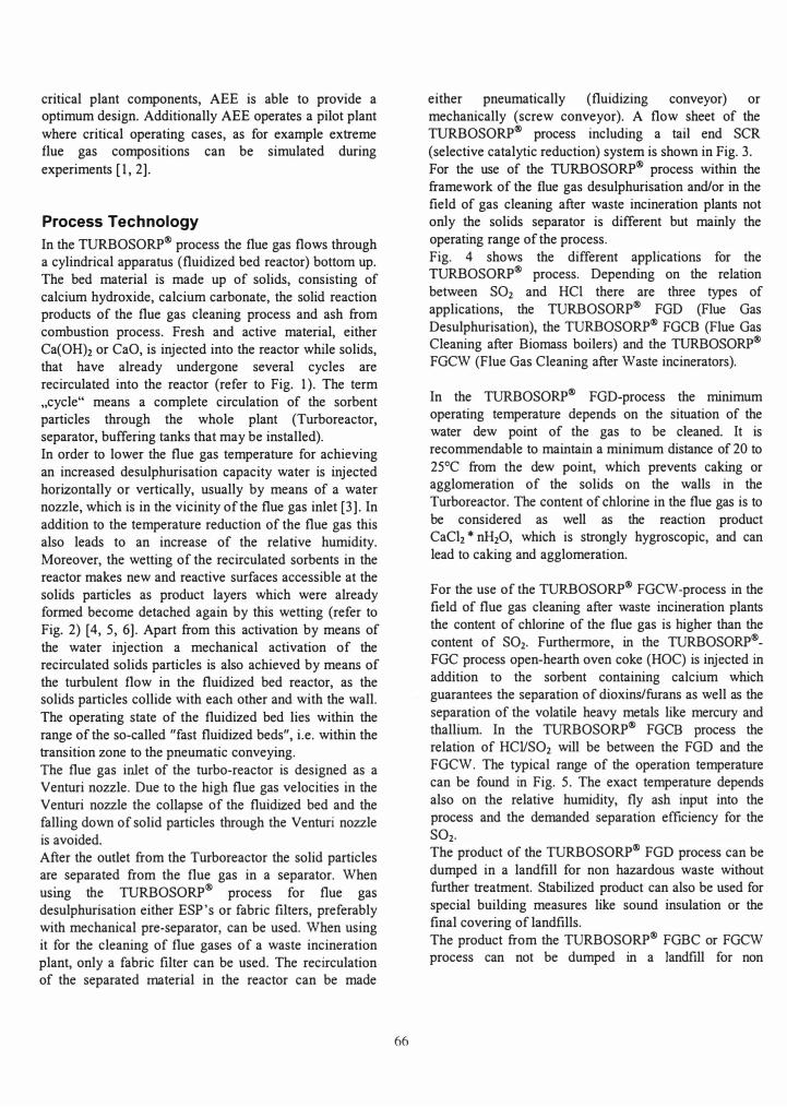
Process Technology
In the TURBOSORP® process the flue gas flows through a cylindrical apparatus (fluidized bed reactor) bottom up. The bed material is made up of solids, consisting of calcium hydroxide, calcium carbonate, the solid reaction products of the flue gas cleaning process and ash from combustion process. Fresh and active material, either Ca(OHh or CaO, is injected into the reactor while solids, that have already undergone several cycles are recirculated into the reactor (refer to Fig. 1). The term "cycle" means a complete circulation of the sorbent particles through the whole plant (Turboreactor, separator, buffering tanks that may be installed). In order to lower the flue gas temperature for achieving an increased desulphurisation capacity water is injected horizontally or vertically, usually by means of a water nozzle, which is in the vicinity of the flue gas inlet [3]. In addition to the temperature reduction of the flue gas this also leads to an increase of the relative humidity. Moreover, the wetting of the recirculated sorbents in the reactor makes new and reactive surfaces accessible at the solids particles as product layers which were already formed become detached again by this wetting (refer to Fig. 2) [4, 5, 6]. Apart from this activation by means of the water injection a mechanical activation of the recirculated solids particles is also achieved by means of the turbulent flow in the fluidized bed reactor, as the solids particles collide with each other and with the wall. The operating state of the fluidized bed lies within the range of the so-called "fast fluidized beds", i.e. within the transition zone to the pneumatic conveying. The flue gas inlet of the turbo-reactor is designed as a Venturi nozzle. Due to the high flue gas velocities in the Venturi nozzle the collapse of the fluidized bed and the falling down of solid particles through the Venturi nozzle is avoided. After the outlet from the Turboreactor the solid particles are separated from the flue gas in a separator. When
. h ® usmg t e TURBOSORP process for flue gas
desulphurisation either ESP's or fabric filters, preferably with mechanical pre-separator, can be used. When using it for the cleaning of flue gases of a waste incineration plant, only a fabric filter can be used. The recirculation of the separated material in the reactor can be made
66
either pneumatically (fluidizing conveyor) or mechanically (screw conveyor). A flow sheet of the TURBOSORP® process including a tail end SCR (selective catalytic reduction) system is shown in Fig. 3. For the use of the TURBOSORP® process within the framework of the flue gas desulphurisation and/or in the field of gas cleaning after waste incineration plants not only the solids separator is different but mainly the operating range of the process. Fig. 4 shows the different applications for the TURBOSORP® process. Depending on the relation between SOz and HCI there are three types of applications, the TURBOSORP® FGD (Flue Gas Desulphurisation), the TURBOSORP® FGCB (Flue Gas Cleaning after Biomass boilers) and the TURBOSORP® FGCW (Flue Gas Cleaning after Waste incinerators).
In the TURBOSORP® FGD-process the minimum operating temperature depends on the situation of the water dew point of the gas to be cleaned. It is recommendable to maintain a minimum distance of 20 to 25°C from the dew point, which prevents caking or agglomeration of the solids on the walls in the Turboreactor. The content of chlorine in the flue gas is to be considered as well as the reaction product CaCh * nHzO, which is strongly hygroscopic, and can lead to caking and agglomeration.
For the use of the TURBOSORP® FGCW-process in the field of flue gas cleaning after waste incineration plants the content of chlorine of the flue gas is higher than the content of SOz. Furthermore, in the TURBOSORP®FGC process open-hearth oven coke (HOC) is injected in addition to the sorbent containing calcium which guarantees the separation of dioxins/furans as well as the separation of the volatile heavy metals like mercury and thallium. In the TURBOSORP® FGCB process the relation of HCVSOz will be between the FGD and the FGCW. The typical range of the operation temperature can be found in Fig. 5. The exact temperature depends also on the relative humidity, fly ash input into the process and the demanded separation efficiency for the SOz. The product of the TURBOSORP® FGD process can be dumped in a landfill for non hazardous waste without further treatment. Stabilized product can also be used for special building measures like sound insulation or the final covering of landfills. The product from the TURBOSORP® FGBC or FGCW process can not be dumped in a landfill for non

hazardous waste without further stabilisation due to the mobilisation of the heavy metals.
Turbosorp versus Spray Absorption
As a supplier of all three typical flue gas cleaning devices (dry, semi-dry and wet systems) AEE built until the middle of the nineties semi-dry spray absorption plants for flue gas desulphurisation after power plants. The last two plants were built in Pilzen and Ledvice,
Czech Republic [7].
The start up phase of the second plant was very difficult
and lasted for approximately one year. Based on these experiences for the spray absorption and on the
successfully start up of the FGD plant in Strakonice,
Czech Republic, in 1998 a comparison between the two technologies (dry and semi dry) showed advantages for
the dry process (using the circulating fluidized bed technology). Especially the following points are of interest:
• Caking in the reactor, especially at the reactor walls,
is a well known problem for the spray absorption
and cannot be prevented. Regularly these deposits have to be removed by the operating staff. If the deposits detach by themselves and fall into the absorber cone, they have to be discharged by means of a crusher and have to be transported to the silo.
Compared with the TURBOSORP® process, there is
no caking found at the reactor walls of the
Turboreactor. The reason is that the high dust load
in the reactor causes a regularly cleaning of the walls. The small amounts of product falling through the Venturi nozzle can be discharged very simply without crushing equipment.
• The availability is reduced using spray absorption through an atomizer replacement in regular
intervalls (3 to 6 weeks). During this replacement the emission values will exceed the limits for 1 or 2
hours. In case of the TURBOSORP® process only
the water injection nozzle is to be checked in regular intervalls (8 to 12 weeks). The checks are made by making a short switching over to the
installed stand by nozzle while the spray pattern of
the main nozzle is checked. No emission limits will be exceeded.
• For the spray absorption piping, tanks, pumps and aggregates for the treatment and transport of the lime and lime slurry all the usual measures have to be taken as they are required for slurry systems. In
67
case of the TURBOSORP® process the only wet plant components are those of the water injection system where pure water is used which is free from
any solids. • Because of the necessarily very long residence
times of approximately 10 seconds low flue gas velocities have to be given in the absorber. However these conditions lead to large diameters of the spray absorber. This in turn leads to large areas required
for the installation. Due to the relatively high superficial gas velocity of 4 to 6 mls the
Turboreactor is considerably of smaller size.
In Table 2 data from the investigated plants can be found. The values show definitely that e.g. the
stoichiometric ratios and water consumptions (due to a greater distance from the water dewpoint in the dry
process) are lower in the TURBOSORP® process. The energy consumption for both types is nearly the same,
whereas in the TURBOSORP® process stack inlet temperatures are higher than in the spray absorption (refer to the data of Table 2 for the Siekierkie plant).
These smaller temperature differences in the TURBOSORP® process are very important reasons for the advantage of the TURBOSORP® process. It is the independence of the amount of injected sorbent and the amount of water. Due to this reason the TURBOSORP®
FGD process needs only a inlet temperature of about 110°C (independent from the S02 raw gas
concentration). For the TURBOSORP® FGCW and FGCB process only a temperature difference between
reactor inlet and outlet of about 30°C is necessary (independent from the inlet flue gas concentrations of
HCI and S02). This gives especially an advantage for the boiler- and
plant-efficiency in case of using the TURBOSORP®
process, because of the possibility to use lower flue gas inlet temperatures for the gas cleaning device.
Through all these reasons and of course through an
advantage in the invest and operation costs it is clear for AEE to push the TURBOSORP® process as best
application if a gas cleaning problem can be solved in a
one step process.

Plant Start up Turbosorp Siekierki
In December 2000 AEE signed the contract with the polish company Elektrim-Megatex to deliver a Turbosorp FGD plant for a new coal fired boiler in the heating plant Siekierki, Warsaw in Poland. The whole project included a new boiler OP-230 (with a nominal steam output of 230 tons/hour), a multicyclone for a 50% separation of fly ash, a Turbosorp-FGD with Turboreactor, product recirculation, sorbent handling and product discharge, the dust separation with preseparator and 8-chamber bagfilter, two lines of steam reheaters and flue gas fans, and the connection to the existing stack. The sorbent handling consists of a 3.000 m3 main sorbent silo for slaked lime with pneumatic sorbent transport over a distance of approx. 500 meters and a 150 m3 day storage silo with sorbent injection into the Turboreactor. The product is discharged into an intermediate product silo and pneumatically transported into a main product silo. In Fig. 6 the plant layout of the FGD Siekierki can be seen (the Turboreactor in red colour, the dust preseparator in yellow and the bagfilter with product recirculation system in blue).
Besides Elektrim-Megatex as the general contractor mainly following companies were involved in this project: Deliveries:
Erection:
Commissioning:
Rafako - boiler; BBP-Environmentbag filter; AEE - Turbosorp-FGD; ABB - I&C part; Mexem-Gliwice -general planning Remak - boiler, Energomontaz - FGD, bagfilter, silos; Elektromontaz -electrical part; ABB - I&C Remak-Rozruch
Time table of the project:
start of project (FGD): start of erection: cold commissioning: warm commissioning: trial run:
guarantee measurements: PAC (prov. acceptance protocol):
December 2000 June 2001 20.04.-07.06.2002 08.06.-14.07.2002 15.07.-14.08.2002 23.08.-28.09.2002 15.11.2002
Polish bituminous coal with a sulfur content of nominal 0,8% (max. 1,2%) is fired in the boiler. The nominal flue gas data can be seen in Table 2.
68
In the engineering phase special emphasis was laid on the optimisation of the flue gas inlet to the Turboreactor and therefore minimising the pressure loss of the Turboreactor. With the aid of Computional Fluid Dynamics (CFD) simulations an optirnal layout could be found (see Fig. 6 and Fig. 7). This design was fmally realised and with begin of July 2001 the erection of the Turboreactor started.
After a cold commissioning period without any bigger problems warm commissioning started on 08.06.2002 with precoating of the filter bags and taking over fust flue gas from the boiler with one of the three coal mills in operation. Although dependent all the time on the boiler operation and optimization works, which resulted in very unstable load and flue gas conditions, FGDoperation could be set and optimised within a very short time period. All the more as certain problems with the bypass damper of the bagfilter and the product recirculation system of the FGD led to a stand still of 10 days during the phase of warm commissioning. So after an all in all very short commissioning period the 720 hours trial run started. But although an outage of the boiler and the remaining equipment of 72 hours was allowed the overall outage time during these 30 days was less than 20 hours. Therefore the trial run could successfully be finished.
In the guarantee measurements the excellent performance of the Turbosorp-FGD was proven. There was not any point were the contractual guarantees couldn't be kept. A S02 outlet concentration of 500 mg/Nm3 (dry, 6% O2) was kept at any boiler load (55-110%) and within the complete range of coals (S02 inlet concentration 1.100 - 3.300 mg/Nm3 dry). The FGD outlet temperature was between 84-90°C, which is a distance of 35-40°C to the adiabatic saturation temperature of the flue gases. The stoichiometric ratio CalS was < 1,05 in any case. The clean gas concentration of dust was within 1-3 mg/Nm3 all the time below the guaranteed limit of < 20 mg/Nm3 (dry, 6% 02)
Since the fust day of start-up not any problem with clogging or deposits in the Turboreactor, the bagfilter or the product recirculation system has occurred. The pressure loss of the Turboreactor which has been optimised by CFD proved to be lower than in the case of former constructions by 20%. By comparing measured with calculated values (as a result from CFD) a good conformity could be found.

Dioxine and Mercury Separation
The TIJRBOSORP® -pilot plant in the Spittelau waste incineration plant was started up after a one year
planning period (starting 1996) in 1997. Because of the suitability of the TURBOSORP® FGC process for the cleaning of flue gases from waste incineration plants the Spittelau household waste incineration plant was selected
as the location of the ftrst plant of that kind since a "real" flue gas of a household waste incineration plant is
available there. Through an advanced gasrnixing system it is possible to increase and decrease the rawgas concentration e.g. for S02 or HCl. The description and explanation of the TURBOSORP® pilot plant can be
found elsewhere [8, 9]. Apart from the reliable respect of the limit values
stipulated by the 17th BIrnSchV for HCI, HF and S02
above all the heavy metal separation, especially the
separation of the easily volatile mercury which is not
bound to particles, as well as the separation of dioxins and furans were examined during the operation of the pilot plant.
As already mentioned above open-hearth oven coke is added for the separation of heavy metals as well as for the separation of dioxins and furans. During the tests a gravimetric flow rate was injected. The boundary limits for the experiments (flue gas conditions) are summarised
in Table 3. In Table 4 the speciftcation of the used
sorbents can be found. All measurements for mercury ,
dioxins and furans were done by an independent measurement company [10).
For the particulate mercury measurement solids were
sampled in a dustftlter, dissolved and analyzed via an ICP-MS system. For the gaseous mercury gas samples
were taken (after draft direction EN 13 211) and analysed via atomic absorption system (AAS).
For the dioxins/furans measurement the condensation method (refer to Fig. 8) was used to get the gas samples
and the analytics were done via HRGC-HRMS-coupling (Fisions Autospec Ultima). The whole measurement
process was done after the direction of VDI 3499 Bl.2 respectively after the draft direction EN 1948-1,2,3.
In Table 5 the measurement results for mercury separation in the TURBOSORP® pilot plant can be
found. In both measurements the mercury limits after 17th BImSch V are fulftlled and the separation efftciency
is around 95%.
In Table 6 the dioxins and furans measurements are summarised. With overall raw gas concentrations of 5.33
69
nglNml respectively 6.23 nglNml (I-TEQ-values) we
reach an excellent separation efftciency of around 99 %. The results taken fron an independent measurement
company show that with this one step process a reliable seperation of mercury, dioxins and furans is possible and that the emission limits after the 17th BlmSchV are fulftlled without any problems.
Conclusions
Since 1996 AEE investigated the TURBOSORP®
process for different gascleaning applications. In the
meantime 5 reference plants are in operation, 2 are under construction. Even the last start up of the plant in Siekierki was ftnished within 60 days without
extraordinary problems.
Through our research activities the reactor design could
be optimized and led to a decrease in the rector pressure
loss of about 20%.
The fact to operate a pilot plant with real flue gas from an waste incinerator gave us the possibility to check plant operation and behavior over an wide range of
changing raw gas concentrations. Therefore we know the optimal operating points for these different applications and can save time and money to optimize new plants in the commissioning phase.
The measurements concerning mercury and
dioxins/furans separation showed also excellent results. As a result of the comparison between spray absorption and TURBOSORP® process, AEE will use for simple
one step gascleaning applications in future only the
TURBOSORP® process.
Acknowledgements
For the support given to our research and development projects we would like to thank FERNW ARME WIEN,
Spittelau waste incineration plant, for the permit of operating the TURBOSORP pilot plant and the support
given in its operation. Also thanks to our research partners, Prof. Dr. G. Krammer, Mr. A. Anzel and Dr. A.
Kavouras, Institut fUr Apparatebau, Mechanische Verfahrenstechnik und Feuerungstechnik, TV Graz, Austria and Dr. C. Weiss and J. Aschner, Institut fUr Verfahrenstechnik, Montanuni Leoben, Austria. Last but not least thanks to our chief plant layouter Mr. R. Wurzinger, AEE, for his extraordinary ideas.

References
[1] Rabenstein G., 2001,"Parameterstudie an der TURBOSORP®-Pilotanlage zur trockenen Rauchgasreinigung nach Milliverbrennungen", Master thesis, TU Graz
[2] Marques lA, Garea A., Irabien A., Reissner H.K., SpieB-Knafl K., Krammer G., 2001, "Desulfurization of flue gas from urban waste incineration by the Turbosorp Process-Contribution of Turbo-Reactor and Bag House Filter", 6th Int. Conference on Technologies and Combustion for a Clean Environment, Porto
[3] Reissner H.K., Anzel A., Krammer G. , Staudinger G., 2001, ''The contribution of drops to the dry S02 removal in circulating fluidized beds", Partec 2001,�uremberg
[4] Brunner C., 1997, "Experirnentelle Simulation eines trockenen Rauchgasentschwefelungsverfahrens in einer Thermowaage", Ph. D. thesis, TU Graz
[5] Krammer G., Brunner C., Staudinger G., 1997, "Reaction of Ca(0H)2 with S02 at Low Temperature", Ind. Eng. Chern. Res. 36, p. 1410-1418
[6] Krammer G., Reissner H.K. , Staudinger G., 2002, "A cyclic activation of calcium hydroxide for enhanced desulfurization", Chern. Eng. Process., 41, 463
[7] Gansley R., Seiwald B., Lamper P., Schonfeldt H., 1997, "Startup and Successful Optimization
Program for the Lime Semi-Dry Flue Gas Desulfurization System for the CEZ Power Plant Ledvice", PowerGeg, Wo?
[8] Reissner H.K., Brunner C., Bamthaler K., SpieBKnafl K., Krammer G., 2001, "Turbosorp - A dry Technology for flue gas desulphurisation (FGD) and flue gas cleaning (FGC)", Powergen Europe 2001, Brussel
[9] Spiess-Knafl K., 2000, "Entwicklung und Optimierung eines trockenen Rauchgasreinigungsverfahrens hinter Mtillverbrennungsanlagen, Ph. D. thesis, TU Wien
[10] Wurst F., 2001, Bericht tiber die Abnahrnemessungen an der Turbosorptionsanlage der BBP-AEE GmbH, Abnahmebericht FTU, Wien
70
Appendix
water ---i>
8
flue gas rJresh sorbent
Fig. 1: Process concept
cleaned flue gas
product
sorbent
Fig. 2: Mechanism for the activation of recirculated sorbent
�----------------------------��----------� I
� , I
�----------------------------��----------�
Fig. 3: Flowsheet Turbosorp-Process

.. .
.
....
1000 3000 5000 "" S02 (mgfNm"l
Fig. 4: Different Turbosorp applications
160 150 140 130 120
�110 ...
100
90 L 80
70
60 10 HCVS02 �w gas [moVmoI]
Fig. 5: Region of operation temperature in Turbosorp applications
Fig. 6: Turbosorp-Siekierki - plant layout
71
Fig. 7: CFD-simulation pressure loss
F
l ...
.
.
.
101015
I W· . ..
-:::-- 100521
-p
1000)9
I , p .
,
I
�� :%
; " .. ".
Fig. 8: DioxinslFurans sampling - condensation Method

Tab. 1: Emission Regulations - Europe
BGBI. 389 Draft Units 17. BlmSchV (Austria) 2000f761EG
Dust mg/Nm'dry 10 10 10
Coes mQ/Nm'dry 10 10 10
HCI mQ/Nm'dry 10 10 10
HF mg/Nm'dry 1 0.5 1 S02 mg/Nm' dry 50 50 50
NOx mg/Nm'dry 200 70 200
CO 50 50 50
HQ molNm'dry 0.03 0.05 0 05
Cd+TI mg/Nm'dry 0 05 0.05 0 05
Sb+As+Pb+C r+Co+Cu+Mn +Ni+V+Sn mg/Nm' dry 0.5 0,5 0.5
PCDDIPCDF ng/Nm'dry 0.1 0,1 0,1 act. 02 (no 11 (with 11 (with
O2 Vol% correction) correction) correction)
Tab. 2: Comparison Turbosorp vs. Spray Absorption
Units Plizen Ledvice Straconize
Flue Gas Flow Nm' th 292.522 512.000 225.000 SOrinlet conc. mglNm'dry 2.307 3.580 3.420 SOreutlet conc. mg/Nm' dry 406 500 500
HCI-inlet conc. mQlNm'dry <50 < 20 < 20
Temp-inlet 'C 149 170 140 Temp-outlet 'C 79 74 76
CaiS moVmol 2 65 1 39 104 Pressure loss mbar 20 20 36 Energy consumption kWh 1.800 730 Water Consumption m'th 12,3 25 8.5
Tab. 3: Flue gas conditions for experiments
Units Pilotplant Flue Gas Flow Nm'/h 2.500 SO,-inlet conc. mglNm'dry 300
HCI-inlet cone. mQ/Nm'dry 960
Temp-inlet ·C 170
Temp-outlet ·C 150
Water Injection ·C 18
CaI(S+0,5 Cil mol/mol 1,8
Tab. 4: Sorbent qualities for experiments
Units Ca(OH),
Ca(OH), Gew.% > 95
MgC03 Gew.% 1,1
BET m'/g 18
Size % 90 <411m
HOC C Gew.% > 95
BET m'/o > 350
Size % 50 < 811m
Siekierkl
235.000 2.500
500
200
140 85 1 1 32
630 7,3
Tab. 5: Results mercury separation
rawgas cleangas sep- eft. particle not sum particle not sum
bounded filterable bounded fi�erable
Ilg/Nm' Ilg/Nm' Ilg/Nm' Ilg/Nm' Ilg/Nm' Ilg/Nm' % 1999
Hg 12 401 413 < 0,2 23 23,2 94 38 2001
Hg 15 43 58 < 0,1 2 2,1 96,38
Tab. 6: Results dioxins/furans separation
rawgas cleangas sep· elf. conc. I·TEQ conc. I·TEQ
ng/Nm' ng/Nm' ng/Nm' ng/Nm' 0/0
1999 sum PCDD 11 0,42 0,31 0,0045 98,93 sum PCDF 44 0,78 1.2 0.022 97,18
sum PCDD/F 55 1.2 1,5 0,027 97,75 2001
sum PCDD 33,6 2,31 0,0148 0,000492 99,98 sum PCDF 39,5 3,92 0.013 0,00137 99,97
sum PCDD/F 73,1 6,23 0,0278 0,00186 99,97
72