Embed Size (px)
Citation preview

Donald B. Cheke www.textualcreations.ca
1
TurboCAD Pro V20.1 – Construction Drawings
(Exterior Raised Panel Door)
Donald B. Cheke
Donald B. Cheke www.textualcreations.ca
2
All rights reserved No part of this document may be reproduced, copied, stored on a retrieval system or transmitted in any form without written permission from the author. The purchaser may, however, print one copy of the document to paper and may make one backup copy of the downloaded material for personal safe keeping. Limitation of Liability While every effort has been taken in the preparation and the writing of this document the author assumes no responsibility for errors and/or omissions nor for the uses of the material and the decisions based on such use. No warranties are made, express or implied with regard to either the contents of the document, its merchant ability or fitness for a particular purpose. The author should not be liable for direct, indirect, special, incidental or consequential damages arising out of the use or inability to use the contents of this document. Special Note All of the work presented within this tutorial is based on TurboCAD Pro V20.1 (64-Bit). Although users of previous versions are welcome to try the tutorial it cannot be stated what results will be achieved. Many changes, some subtle and others not so subtle, are made with each program revision. Although many steps and directions would be generic some may not be. The same can be said for tools between versions. Older versions may not have the same tools as Pro V20.1 and if the same tools are available the tools themselves may have been revised and hence, work in a different manner than they previously did.
Copyright © 2013 Donald B. Cheke TurboCAD is a registered trademark of IMSI/Design.
Published by: Donald B. Cheke Saskatoon, SK Canada Visit: www.textualcreations.ca

Donald B. Cheke www.textualcreations.ca
3
Table of Contents Table of Contents ......................................................................................................................................................... 3 Introduction .................................................................................................................................................................. 4 Drawing Engine Selection ........................................................................................................................................... 6 Setup .............................................................................................................................................................................. 8 2D Door Frame Profiles ............................................................................................................................................ 29 2D Door Profiles ......................................................................................................................................................... 61 3D Construction - Door .............................................................................................................................................. 91 3D Construction - Frame ........................................................................................................................................ 146 Threshold Screws .................................................................................................................................................... 168 Door Modifications & Hinges ................................................................................................................................ 193 Leaded Glass Window ............................................................................................................................................ 207 3D Fillets .................................................................................................................................................................. 211 Materials Application ............................................................................................................................................. 218 Named Views ........................................................................................................................................................... 253 Saving the Rendered Image ................................................................................................................................. 262 Additional Named Views ........................................................................................................................................ 265 Exploded View ......................................................................................................................................................... 267 Paper Space Setup ................................................................................................................................................. 279 Paper Space – Viewports ...................................................................................................................................... 286 Paper Space – Drafting Palette Objects ............................................................................................................. 296 Paper Space – Annotations & Dimensions ........................................................................................................ 323 Printing ..................................................................................................................................................................... 360

Donald B. Cheke www.textualcreations.ca
4
Introduction At one point in time I received an email with a request to create a tutorial that would lead a reader through the steps necessary to create a set of construction drawings. The request specified a double hung window or an entry door. Initially I had my mind set on illustrating the double hung window but it quickly became apparent that the window was just too complex to fit into a tutorial of reasonable length. The entry door, although complex enough, requires fewer components and so seemed much more suitable for a tutorial. It is by all means adequate to illustrate the processes necessary to create a set of construction drawings. This tutorial was originally written for TurboCAD Pro V15 but has been fully revised and updated for TurboCAD Pro V20.1. There have been many great additions to the program since V15. I hope that you will enjoy the tutorial as much as I had creating it. Best regards, Don Within the tutorial the reader will be led through each keystroke to create the framed 36" entry door illustrated on the cover of the tutorial. Aside from learning how to draw in TurboCAD, the user will learn how to insert standard lighting and how to render their drawing and save it in a high resolution image format. The reader will also learn how to utilize paper space where the construction drawings will be created utilizing viewports, inserted drafting palette objects (views/inserts), dimensions and annotations. This tutorial is in no way intended to teach door construction or design but rather it is intended to teach the use of some of the tools that TurboCAD has to offer and to introduce the new user to a drawing methodology. The author feels confident that the techniques outlined within the tutorial can help lay the foundation for future successful TurboCAD drawing and illustration for even the newest user. As with any technically advanced software, the user is generally faced with a steep learning curve. It is the hope of the author that the money and time spent working through a Textual Creations tutorial will help ease the learning and allow the reader to come away feeling confident that they made a wise decision. This tutorial will assume that the reader has the Platinum edition of TurboCAD Pro V20.1 (64-Bit), although no platinum mechanical or platinum architectural specific tools are used, that the author is aware of. The author does not have the 32-Bit version of TurboCAD V20, but did save the final drawing back to V18. The model opened and rendered in V18 without issue. There are many ways to approach a project and it is likely that each person using the program would proceed in very different ways, so be open to alternative methods as experience builds. This tutorial assumes that the beginner has studied the desktop to some degree and can locate most of the tools. Since there are endless desktop configurations that can be set up in TurboCAD the author has opted to illustrate the required tools with the TurboCAD Classic user interface with its Office 2003 theme and the default toolbars in their undocked format.

Donald B. Cheke www.textualcreations.ca
5
Please remember that any supplied files and images are for use within the tutorial only and may not be shared or sold to others. Place the supplied images in a permanent location on the user’s hard drive. For those working through the tutorial in pre-V18 versions please note that most of the functions described in the tutorial, as being on the Modify menu, were on the Format menu in previous versions of the program. Also note that render times are much better in V18, V19 and V20 than one will see if using previous versions of TurboCAD. TurboCAD now uses Multi-Threading for renders and can make use of multiple processors. The author has a two year old, off the shelf, Acer with 6 processers and has enabled 5 for rendering. This is looked at as part of the set up further along. Lastly, the Copy in Place tool has finally been reintroduced into TurboCAD as a permanent tool. Users who don't have this new tool will need to use the Make Copy method. That is to select the object to copy in place, select the Make Copy tool to turn it on, tab into the first field on the Inspector Bar – but don't change anything – simply press Enter. Select the Make Copy tool again to turn it off.

Donald B. Cheke www.textualcreations.ca
29
2D Door Frame Profiles The hinge side jamb profile will be created first – working toward the shape indicated below.
Switch to World Plan view.
Select the Rectangle tool from the Line toolbar.
Select Blue from the color dropdown menu on the Property toolbar.
Place the cursor over a grid intersection in the drawing and press the G key to place the first point of the rectangle (G SEKE snap). Move the cursor in a left upwardly direction for a short distance and then Tab into the Inspector Bar and enter 1 1/4 in the Size A field and 6 3/4 in the Size B field. Press Enter. (Note: if a user knows the decimal equivalents they can be typed instead of fractions and the program will automatically create them, as the space units is set to fractions)

Donald B. Cheke www.textualcreations.ca
30
V SEKE snap the first point of the next rectangle to the lower right corner of the last rectangle. Move the cursor in a left upwardly direction for a short distance and then Tab into the Inspector Bar and enter 9/16 in the Size A field and 2 1/8 in the Size B field. Press Enter.
V SEKE snap the first point of the next rectangle to the top left corner of the last rectangle. Move the cursor in a right upwardly direction for a short distance and then Tab into the Inspector Bar and enter 1/16 in the Size A field and 3/8 in the Size B field. Press Enter. In progress below.
Select the 2D Subtract tool from the Boolean & Facet toolbar.
Select the large rectangle as the object to subtract from. Select Finish selecting.

Donald B. Cheke www.textualcreations.ca
47
Right mouse click and select Close from the local menu. Press Ctrl + K to open the Select by Colors dialogue. Select Green and click OK. Press Delete to remove the trace aids. Select the Fillet2D tool from the Modify toolbar.
Tab into the Inspector Bar and enter 1/8 in the Radius field. Press Enter.
Using two left mouse clicks on the line and the arc that make the upper inside corner perform the fillet. In progress below.
Press the Space Bar to exit the tool. Select both profiles of the weather stripping. Press D SEKE and relocate (M SEKE) the reference point to the middle of the top line of the blue profile.

Donald B. Cheke www.textualcreations.ca
48
Left mouse click on the reference point of the selection to pick it up. Move the cursor to the top line of the dado in the left door jamb profile and M SEKE snap the selection in place. In progress below.
Press Esc to deselect the selection. Compressible objects (weather stripping) will be illustrated in their uncompressed form and, as such, will intersect the surrounding profiles. This is acceptable and likely necessary so that the true form can be realized in the construction drawings. If necessary a user could always create a compressed set to show for comparison.

Donald B. Cheke www.textualcreations.ca
77
With the profiles still selected Tab into the Inspector Bar and enter 1/8 in the Delta X field and 1 15/16 in the Delta Z field. Press Enter.
Press Esc to deselect the selection. One more profile is required before getting into the 3D construction of the tutorial. This is the sweep seal (lower door seal) which will now be created in the same fashion as the other profiles have thus far – working toward the shape indicated below.
Switch to Left view. Select Plane by Active View from the Workplane toolbar.

Donald B. Cheke www.textualcreations.ca
78
Select the Rectangle tool from the Line toolbar. Select Green from the color dropdown menu on the Property toolbar.
G SEKE snap the first point of the rectangle to a grid intersection in a clear area of the drawing to the right of the profiles. Move the cursor in a right upwardly direction for a short distance and then Tab into the Inspector Bar and enter 1 23/32 in the Size A field and 3/64 in the Size B field. Press Enter.
V SEKE snap the first point of the next rectangle to the lower left corner of the first rectangle. Move the cursor in a right upwardly direction for a short distance and then Tab into the Inspector Bar and enter 3/64 in the Size A field and 3/64 in the Size B field. Press Enter.
V SEKE snap the first point of the next rectangle to the lower right corner of the last rectangle. Move the cursor in a right downwardly direction for a short distance and then Tab into the Inspector Bar and enter 9/16 in the Size A field and 31/64 in the Size B field. Press Enter.
Press the Space Bar to exit the tool. Select the last rectangle. Press D SEKE and relocate (M SEKE) the reference point to the middle of the top line of the selection.
With the rectangle still selected, select the Copy in Place tool one time. Left mouse click on the reference point of the selection to pick it up. Move the cursor to the bottom line of the thin rectangle and M SEKE snap the selection in place. With the rectangle still selected, Tab into the Inspector Bar and enter 3/64 in the Size X field. Press Enter.

Donald B. Cheke www.textualcreations.ca
91
3D Construction - Door It is now time to create the 3D components and many new layers will be created that will help with managing the various objects. Open the Design Director palette. Left mouse click the New Layer icon at the top of the palette to create a new named layer.
Enter 2D Profiles in the Layer name field and click OK.
Left mouse click the New Layer icon at the top of the palette again to create a new named layer. Enter Hinge Jamb in the Layer name field and click OK.
In the same manner create thirteen new layers in order, as indicated in the picture below. There will be some others but they will be addressed later in the tutorial.

Donald B. Cheke www.textualcreations.ca
92
Left mouse click the eye icons for all the new layers. This will turn off (not visible) those layers in the drawing and anything assigned to them will not be visible in the drawing. It should be noted that layer 0 should always remain on as the program uses this layer for internal processes. (A user can turn them all off (or on) en masse by selecting all the layer names and then selection one of the eye icons.)
Switch to Isometric SE view. Select the raised panel profile and then select the Copy in Place tool one time.
Press D SEKE and relocate (M SEKE) the reference point to the middle of the right line of the selection. With the profile still selected, Tab into the Inspector Bar and enter 90 in the Y Rotation field. Press Enter.

Donald B. Cheke www.textualcreations.ca
117
Select the left stile and assign it to the Hinge Stile layer. In progress below. (Assigning via the Design Director palette)
Select the right stile and assign it to the Knob Stile layer. Select the lock rail and assign it to the Lock Rail layer. Select the mullion and assign it to the Mullion layer. Select the bottom rail and assign it to the Bottom Rail layer. Create two new layers, one called Window and one called Window Risers.
Turn both new layers off.

Donald B. Cheke www.textualcreations.ca
118
Select the window and assign it to the Window layer. Select the two small window risers and assign them to the Window Risers layer. Locate the window molding profile in the drawing and zoom in on it. Select the window molding profile. Press D SEKE and relocate (V SEKE) the reference point to the inner corner as indicated in the picture below.
With the molding still selected, Tab into the Inspector Bar and enter 180 in the X Rotation field. Press Enter.
Left mouse click on the reference point of the selection to pick it up. Move the cursor to the left line of the blue window opening profile and M SEKE snap the selection in place. In progress below.

Donald B. Cheke www.textualcreations.ca
146
3D Construction - Frame It is now time to create the 3D door frame. Select the Simple Extrude tool from the 3D Object toolbar. Turn off the Two sided extrude option. Select the left jamb profile as the object to extrude. Tab into the Inspector Bar and enter 82 3/4 in the Height field. Press Enter.
Select the right jamb profile as the object to extrude. Tab into the Inspector Bar and enter -82 3/4 in the Height field. Press Enter. (Remember, this profile was mirror copied).
Press the Space Bar to exit the tool. The left jamb can also be used for the header. Select the left jamb and then select the Copy in Place tool one time.

Donald B. Cheke www.textualcreations.ca
147
Press D SEKE and relocate (V SEKE) the reference point to the top back outer corner of the selection.
With the jamb still selected, Tab into the Inspector Bar and enter 90 in the Y Rotation field. Press Enter.
Select Explode 1X from the Format menu at the top of the TurboCAD desktop so that the extrusion can be resized.
Tab into the Inspector Bar and enter 0 in the X Position field.
Switch to World Plan view. Place the cursor over the left line of the selection and when the double arrow cursor appears left mouse click to pick up the edge. Move the cursor to the inside edge of the left door jamb recess and V SEKE snap at the corner as indicated in the picture below. In progress below.

Donald B. Cheke www.textualcreations.ca
168
Threshold Screws It is now time to create the threshold screws. Turn on the Threshold layer. Select the two stacked components of the threshold and assign them to layer 0.
Turn off the Threshold layer. Press Esc to deselect the selection.
The threshold screws raise and lower the top element of the two to adjust for an optimal seal at the bottom of the door. The system will require a T-nut and a threaded spinner that is glued into the upper component. Switch to Left view. Select Plane by Active View from the Workplane toolbar.
Donald B. Cheke www.textualcreations.ca
169
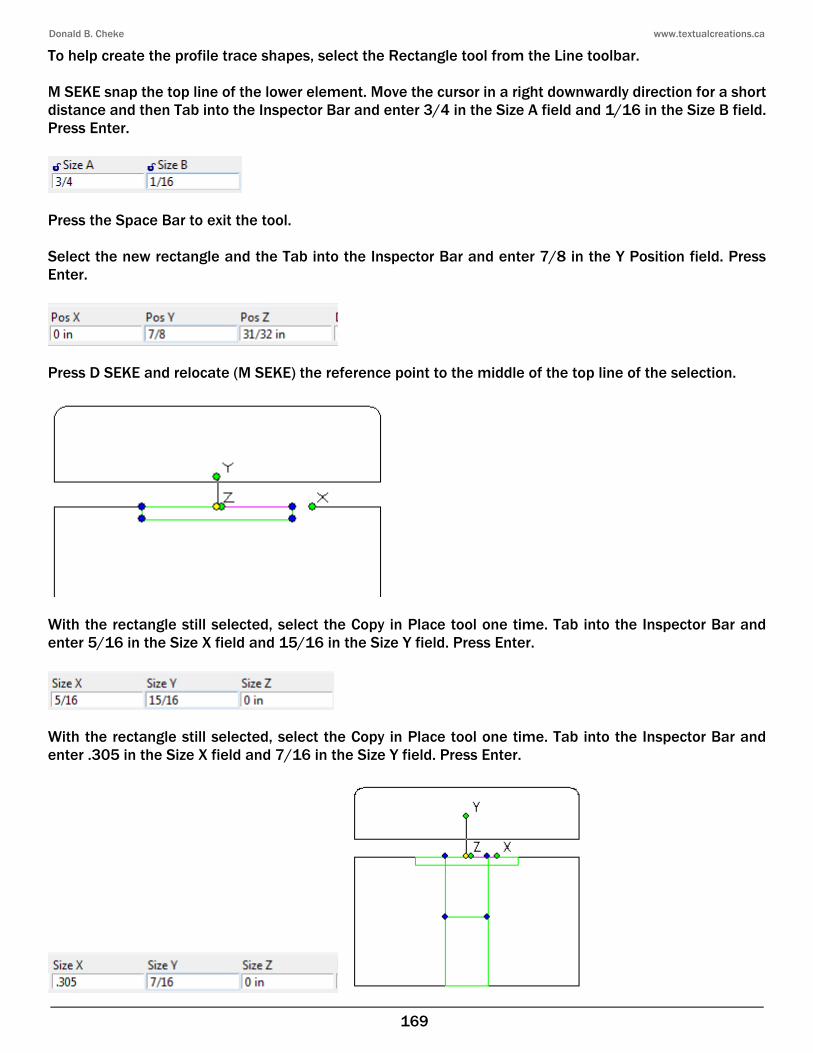
To help create the profile trace shapes, select the Rectangle tool from the Line toolbar. M SEKE snap the top line of the lower element. Move the cursor in a right downwardly direction for a short distance and then Tab into the Inspector Bar and enter 3/4 in the Size A field and 1/16 in the Size B field. Press Enter.
Press the Space Bar to exit the tool. Select the new rectangle and the Tab into the Inspector Bar and enter 7/8 in the Y Position field. Press Enter.
Press D SEKE and relocate (M SEKE) the reference point to the middle of the top line of the selection.
With the rectangle still selected, select the Copy in Place tool one time. Tab into the Inspector Bar and enter 5/16 in the Size X field and 15/16 in the Size Y field. Press Enter.
With the rectangle still selected, select the Copy in Place tool one time. Tab into the Inspector Bar and enter .305 in the Size X field and 7/16 in the Size Y field. Press Enter.
Donald B. Cheke www.textualcreations.ca
186
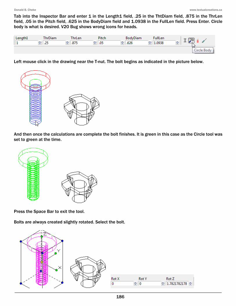
Tab into the Inspector Bar and enter 1 in the Length1 field, .25 in the ThtDiam field, .875 in the ThrLen field, .05 in the Pitch field, .625 in the BodyDiam field and 1.0938 in the FullLen field. Press Enter. Circle body is what is desired. V20 Bug shows wrong icons for heads.
Left mouse click in the drawing near the T-nut. The bolt begins as indicated in the picture below.
And then once the calculations are complete the bolt finishes. It is green in this case as the Circle tool was set to green at the time.
Press the Space Bar to exit the tool. Bolts are always created slightly rotated. Select the bolt.
Donald B. Cheke www.textualcreations.ca
187
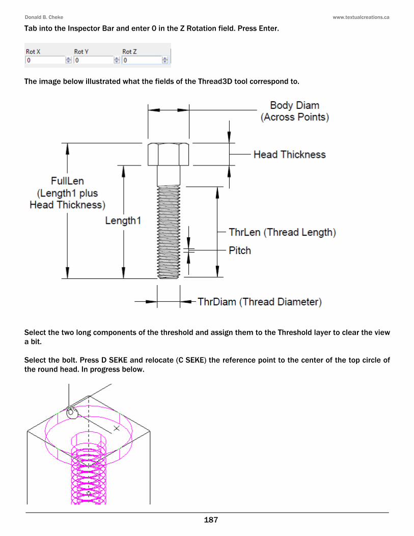
Tab into the Inspector Bar and enter 0 in the Z Rotation field. Press Enter.
The image below illustrated what the fields of the Thread3D tool correspond to.
Select the two long components of the threshold and assign them to the Threshold layer to clear the view a bit. Select the bolt. Press D SEKE and relocate (C SEKE) the reference point to the center of the top circle of the round head. In progress below.

Donald B. Cheke www.textualcreations.ca
207
Leaded Glass Window It is now time to insert the leaded glass window. A simple pattern was created by the author in TurboCAD and the file supplied. It would have been beneficial to illustrate the construction of the window within the tutorial but it would have added significantly to the size of the tutorial. Since there is still much work ahead it was deemed necessary to supply the constructed window. Update: A video is supplied detailing the construction but use the supplied one at this point. See: Leaded Window Construction.mp4 Turn on the Window layer. Select Plane by World from the Workplane toolbar. Select the original window panel and then select Green from the color dropdown menu on the Property toolbar.
From the File menu at the top of the TurboCAD desktop select Open. Located the supplied file Leaded Glass Window.tcw and click Open.
The file opens with the profiles used and two copies of the window, the vertical one rotated 180° so it is ready to insert into the door drawing.
Donald B. Cheke www.textualcreations.ca
222
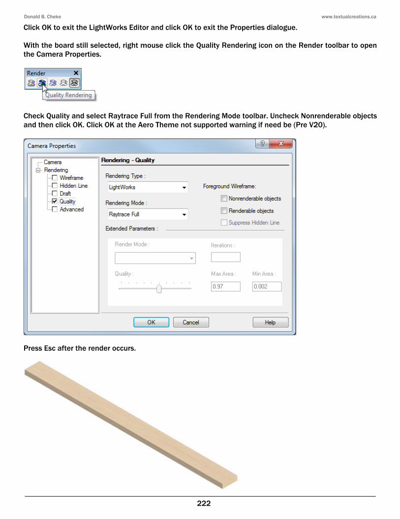
Click OK to exit the LightWorks Editor and click OK to exit the Properties dialogue. With the board still selected, right mouse click the Quality Rendering icon on the Render toolbar to open the Camera Properties.
Check Quality and select Raytrace Full from the Rendering Mode toolbar. Uncheck Nonrenderable objects and then click OK. Click OK at the Aero Theme not supported warning if need be (Pre V20).
Press Esc after the render occurs.

Donald B. Cheke www.textualcreations.ca
223
Zoom in on the right end of the board for a closer look.
Select the Wireframe tool to end the render.
Select the new board and then select the Copy in Place tool one time. With the board still selected, Tab into the Inspector Bar and enter .1 in the three Scale fields. Press Enter to create the seed.
With the seed board still selected, right mouse click and select Rubber Stamp from the local menu. Move the cursor to the edge of the jamb header and E SEKE snap a copy in place. In progress below.
Donald B. Cheke www.textualcreations.ca
277
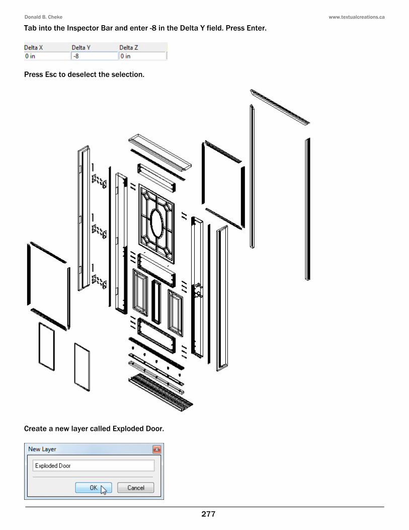
Tab into the Inspector Bar and enter -8 in the Delta Y field. Press Enter.
Press Esc to deselect the selection.
Create a new layer called Exploded Door.
Donald B. Cheke www.textualcreations.ca
309
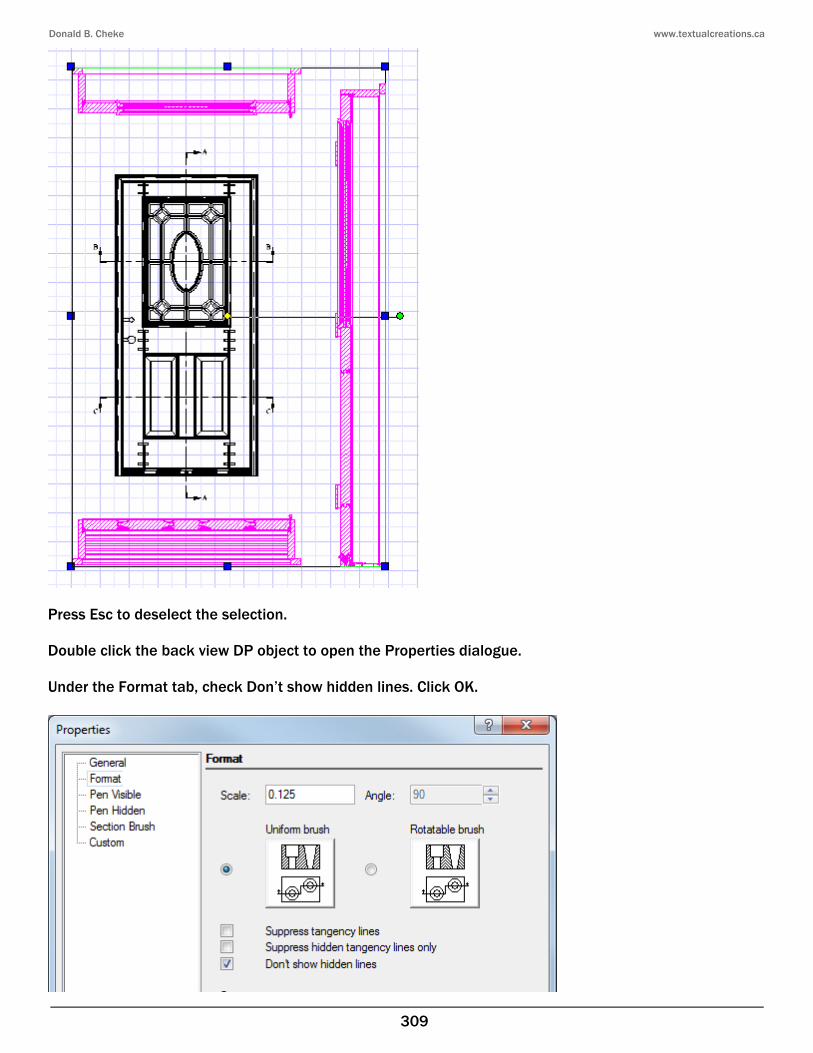
Press Esc to deselect the selection. Double click the back view DP object to open the Properties dialogue. Under the Format tab, check Don’t show hidden lines. Click OK.

Donald B. Cheke www.textualcreations.ca
310
Select the Section B DP object. Tab into the Inspector Bar and enter 19 in the Y Position field. Press Enter.
Select the Section C DP object. Tab into the Inspector Bar and enter 2 in the Y Position field. Press Enter.
Select the Section A DP object. Tab into the Inspector Bar and enter 18.5 in the X Position field. Press Enter. Press Esc to deselect the selection.
Two Fragmental Views will now be created. Select the Circle Center & Point tool from the Circle/Ellipse toolbar.
Select Black from the color dropdown menu on the Property toolbar.