Embed Size (px)
Citation preview

Donald B. Cheke www.textualcreations.ca
1
TurboCAD Pro V17.2 – Sprockets & Chain
Donald B. Cheke

Donald B. Cheke www.textualcreations.ca
2
Copyright © 2010 Donald B. Cheke TurboCAD is a registered trademark of IMSI/Design.
Published by: Donald B. Cheke Saskatoon, SK Canada Visit: www.textualcreations.ca
All rights reserved No part of this document may be reproduced, copied, stored on a retrieval system or transmitted in any form without written permission from the author. The purchaser may, however, print one copy of the document to paper and may make one backup copy of the downloaded material for personal safe keeping. Limitation of Liability While every effort has been taken in the preparation and the writing of this document the author assumes no responsibility for errors and/or omissions nor for the uses of the material and the decisions based on such use. No warranties are made, express or implied with regard to either the contents of the document, its merchant ability or fitness for a particular purpose. The author should not be liable for direct, indirect, special, incidental or consequential damages arising out of the use or inability to use the contents of this document. Special Note All of the work presented within this tutorial is based on TurboCAD Pro V17.2. Although users of previous versions are welcome to try the tutorial it cannot be stated what results will be achieved. Many changes, some subtle and others not so subtle, are made with each program revision. Although many steps and directions would be generic some may not be. The same can be said for tools between versions. Older versions may not have the same tools as Pro V17.2 and if the same tools are available the tools themselves may have been revised and hence, work in a different manner than they previously did.

Donald B. Cheke www.textualcreations.ca
3
Table of Contents Table of Contents ......................................................................................................................................................... 3 Introduction .................................................................................................................................................................. 4 Setup .............................................................................................................................................................................. 6 2D Sprocket Layout ................................................................................................................................................... 21 2D Sprocket Profiles to 3D Sprockets .................................................................................................................... 44 2D Chain Link Layout ................................................................................................................................................ 64 2D Link Profiles to 3D Links .................................................................................................................................... 68 Materials Application ................................................................................................................................................ 83 Named View ................................................................................................................................................................ 89 Render Scene Luminance ........................................................................................................................................ 91 Render Scene Environment ..................................................................................................................................... 95 Saving the Rendered Image..................................................................................................................................... 98 Appendix – An Important Note about TurboCAD Materials ............................................................................. 101

Donald B. Cheke www.textualcreations.ca
4
Introduction Laying out sprockets and chains within TurboCAD can certainly seem a daunting task for any new user. But like most things in the world of CAD, it is manageable when someone takes the time to explain the process. Within this tutorial the reader will be led through each keystroke to produce all components of the sprockets and chain that are illustrated on the cover of the tutorial. The reader will learn how to set up their drawing, how to draw the required 2D profiles and use those 2D profiles to create the 3D components. The reader will also learn how to insert standard lighting and how utilize render scene luminance. The reader will learn how to establish a render scene environment and the reader will learn how to render their drawing and save it in a high resolution image format. This tutorial is in no way intended to teach the fundamentals of sprocket and chain design but rather it is intended to teach the use of some of the tools that TurboCAD has to offer and to introduce the new user to a drawing methodology. The author feels confident that the techniques outlined within the tutorial can help lay the foundation for future successful TurboCAD drawing and illustration for even the newest user. As with any technically advanced software, the user is generally faced with a steep learning curve. It is the hope of the author that the money and time spent working through a Textual Creations tutorial will help ease the learning and allow the reader to come away feeling confident that they made a wise decision. This tutorial will assume that the reader has the Platinum edition of TurboCAD Pro V17.2 with its extra architectural and mechanical tools, although no Platinum specific tools are used that the author is aware of. There are many ways to approach a project and it is likely that each person using the program would proceed in very different ways, so be open to alternative methods as experience builds. What is important is that the user becomes familiar with the objects that they wish to model and begin to look at them in a different way than they might otherwise do. What primitive shapes make up the whole? What will be required of these primitive shapes early in the drawing and how will this affect needs further along? What component or components should be started with? Many questions can only be answered through experience, but hopefully some of them will be answered by the time the beginner has worked through this tutorial. There is a great deal covered in this tutorial and the author urges the beginner to be patient, to read very carefully and to take the time necessary to do a good job. Try to enjoy the process as much as you will enjoy the final results. This tutorial assumes that the beginner has studied the desktop to some degree and can locate most of the tools. Since there are endless desktop configurations that can be set up in TurboCAD the author has opted to illustrate the required tools with the Office 2000 user interface, and the default toolbars in their undocked format (Office 2000 theme).
Donald B. Cheke www.textualcreations.ca
5
Please remember that any supplied images and files are for use within the tutorial only and may not be shared or sold to others. Place tutorial images in a permanent location on the hard drive.

Donald B. Cheke www.textualcreations.ca
21
2D Sprocket Layout Switch to Front view.
Select Plane by Active View from the Workplane toolbar. Scroll in so the grid is visible on screen. The profiles for a 14 tooth upper sprocket and a 25 tooth lower sprocket will now be created, beginning with the lower sprocket. The image below illustrates what is being worked towards. Once complete, a single tooth from each set will be traced, extruded and then radial copied.
Select the Polygon tool from the Line toolbar.
Select Sienna from the color dropdown menu on the Property toolbar.
Tab into the Inspector Bar and enter 25 in the Sides field. Press Enter.

Donald B. Cheke www.textualcreations.ca
44
Press Esc to exit the Rubber Stamp tool. Press Ctrl + K to open the Select by Colors dialogue. Select By Layer (result of the grouping) and click OK.
Select the Mirror Copy tool from the Copy toolbar. V SEKE snap the lower point of the upper sprocket segment profile to define the first point of the mirroring line. Press and hold the Shift key down. Move the cursor downward a short distance and then left mouse click to define the second point of the mirroring line. Release the Shift key. In progress below.
Turn off the 2D layer. 2D Sprocket Profiles to 3D Sprockets Switch to Isometric SE view. Select the Simple Extrude tool from the 3D Objects toolbar.
Select the Two sided extrude option.

Donald B. Cheke www.textualcreations.ca
45
Select the upper profile as the object to extrude. Tab into the Inspector Bar and enter .25 in the Height field. Press Enter to extrude .25 in both directions.
Select the lower profile as the object to extrude. Tab into the Inspector Bar and enter .25 in the Height field. Press Enter to extrude .25 in both directions.
Press Ctrl + K to open the Select by Colors dialogue. Select Blue and click OK. Assign the selection to the 2D layer. Select the upper sprocket segment. Select the Radial Copy tool from the Copy toolbar. V SEKE snap the lower forward vertex to define the center of the arc. In progress below.
Tab into the Inspector Bar and enter 14 in the Sets field. Press Enter.
Select the lower sprocket segment. Select the Radial Copy tool from the Copy toolbar. V SEKE snap the upper forward vertex to define the center of the arc. In progress below.
Donald B. Cheke www.textualcreations.ca
69
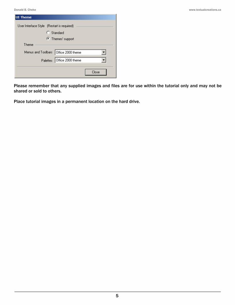
Select the central .5 inch circle as the object to extrude. Tab into the Inspector Bar and enter .255 in the Height field. Press Enter.
Select the right .5 inch circle as the object to extrude. Tab into the Inspector Bar and enter .255 in the Height field. Press Enter.
Press the Space Bar to exit the tool. Select Workplane by Origin from the Workplane toolbar.
Place the cursor by the edge of the roller, as indicated in the picture below, and C SEKE snap to define the new workplane. In progress below.
Select the Blue link profile and then select Place on Workplane from the Format menu at the top of the TurboCAD desktop. Select the Simple Extrude tool from the 3D Objects toolbar. Disengage the Two sided extrude option. Select the Blue link profile as the object to extrude. Tab into the Inspector Bar and enter .085 in the Height field. Press Enter.

Donald B. Cheke www.textualcreations.ca
70
Press the Space Bar to exit the tool. Select Workplane by Origin from the Workplane toolbar.
Place the cursor by the edge of the last extrusion, as indicated in the picture below, and C SEKE snap to define the new workplane. In progress below.
Select the Forest Green link profile and then select Place on Workplane from the Format menu at the top of the TurboCAD desktop. Select the Simple Extrude tool from the 3D Objects toolbar. Select the Forest Green link profile as the object to extrude. Tab into the Inspector Bar and enter .085 in the Height field. Press Enter.
Engage the Two sided extrude option. Select the left .2 inch red circle as the object to extrude. Tab into the Inspector Bar and enter .45 in the Height field. Press Enter.
Select the central .2 inch red circle as the object to extrude. Tab into the Inspector Bar and enter .45 in the Height field. Press Enter.
Donald B. Cheke www.textualcreations.ca
98
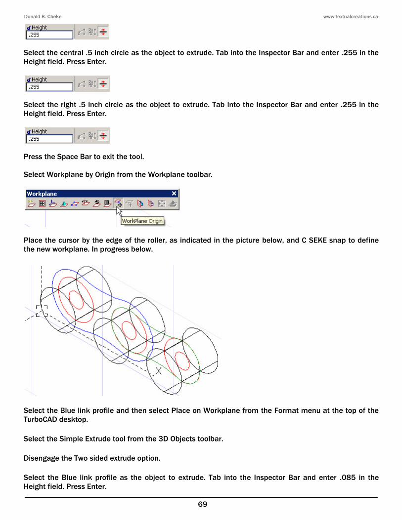
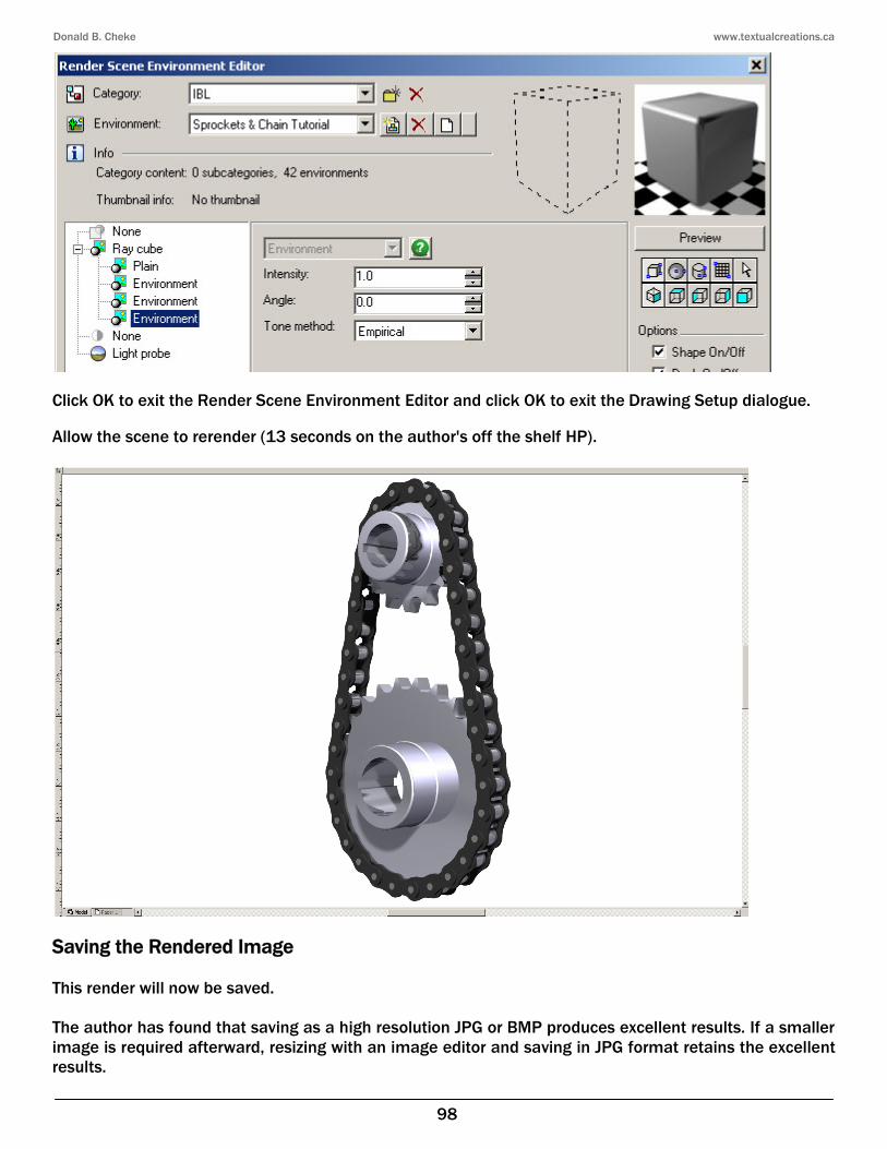
Click OK to exit the Render Scene Environment Editor and click OK to exit the Drawing Setup dialogue. Allow the scene to rerender (13 seconds on the author's off the shelf HP).
Saving the Rendered Image This render will now be saved. The author has found that saving as a high resolution JPG or BMP produces excellent results. If a smaller image is required afterward, resizing with an image editor and saving in JPG format retains the excellent results.