Embed Size (px)
Citation preview
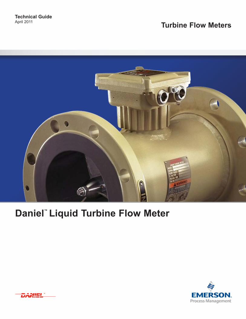
Technical GuideApril 2011 Turbine Flow Meters
Daniel™ Liquid Turbine Flow Meter
TM

Technical GuideApril 2011
Page 1
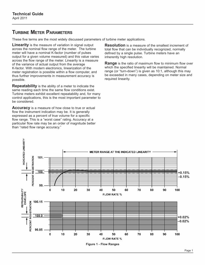
+0.15%–0.15%
+0.02%–0.02%
Linearity is the measure of variation in signal output across the nominal flow range of the meter. The turbine meter will have a nominal K-factor (number of pulses output for a given volume measured) and this value varies across the flow range of the meter. Linearity is a measure of the variance of actual output from the average K-factor. With modern electronics, linearization of the meter registration is possible within a flow computer, and thus further improvements in measurement accuracy is possible.
Repeatability is the ability of a meter to indicate the same reading each time the same flow conditions exist. Turbine meters exhibit excellent repeatability and, for many control applications, this is the most important parameter to be considered.
Accuracy is a measure of how close to true or actual flow the instrument indication may be. It is generally expressed as a percent of true volume for a specific flow range. This is a “worst case” rating. Accuracy at a particular flow rate may be an order of magnitude better than “rated flow range accuracy.”
Figure 1 - Flow Ranges
Resolution is a measure of the smallest increment of total flow that can be individually recognized, normally defined by a single pulse. Turbine meters have an inherently high resolution.
Range is the ratio of maximum flow to minimum flow over which the specified linearity will be maintained. Normal range (or “turn-down”) is given as 10:1, although this may be exceeded in many cases, depending on meter size and required linearity.
Turbine MeTer ParaMeTers
These five terms are the most widely discussed parameters of turbine meter applications.
Technical GuideApril 2011
Page 2
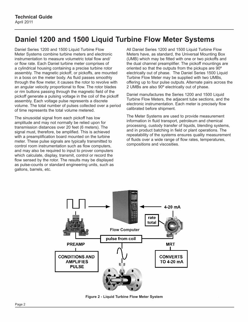
Daniel Series 1200 and 1500 Liquid Turbine Flow Meter Systems combine turbine meters and electronic instrumentation to measure volumetric total flow and/or flow rate. Each Daniel turbine meter comprises of a cylindrical housing containing a precise turbine rotor assembly. The magnetic pickoff, or pickoffs, are mounted in a boss on the meter body. As fluid passes smoothly through the flow meter, it causes the rotor to revolve with an angular velocity proportional to flow. The rotor blades or rim buttons passing through the magnetic field of the pickoff generate a pulsing voltage in the coil of the pickoff assembly. Each voltage pulse represents a discrete volume. The total number of pulses collected over a period of time represents the total volume metered.
The sinusoidal signal from each pickoff has low amplitude and may not normally be relied upon for transmission distances over 20 feet (6 meters). The signal must, therefore, be amplified. This is achieved with a preamplification board mounted on the turbine meter. These pulse signals are typically transmitted to control room instrumentation such as flow computers, and may also be required to input to prover computers which calculate, display, transmit, control or record the flow sensed by the rotor. The results may be displayed as pulse-counts or standard engineering units, such as gallons, barrels, etc.
Flow Computer
Figure 2 - Liquid Turbine Flow Meter System
All Daniel Series 1200 and 1500 Liquid Turbine Flow Meters have, as standard, the Universal Mounting Box (UMB) which may be fitted with one or two pickoffs and the dual channel preamplifier. The pickoff mountings are oriented so that the outputs from the pickups are 90º electrically out of phase. The Daniel Series 1500 Liquid Turbine Flow Meter may be supplied with two UMBs, offering up to four pulse outputs. Alternate pairs across the 2 UMBs are also 90º electrically out of phase.
Daniel manufactures the Series 1200 and 1500 Liquid Turbine Flow Meters, the adjacent tube sections, and the electronic instrumentation. Each meter is precisely flow calibrated before shipment.
The Meter Systems are used to provide measurement information in fluid transport, petroleum and chemical processing, custody transfer of liquids, blending systems, and in product batching in field or plant operations. The repeatability of the systems ensures quality measurement of fluids over a wide range of flow rates, temperatures, compositions and viscosities.
Daniel 1200 and 1500 Liquid Turbine Flow Meter Systems
Technical GuideApril 2011
Page 3
Turbine MeTer Theory
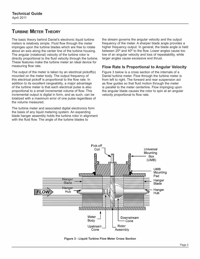
The basic theory behind Daniel’s electronic liquid turbine meters is relatively simple. Fluid flow through the meter impinges upon the turbine blades which are free to rotate about an axis along the center line of the turbine housing. The angular (rotational) velocity of the turbine rotor is directly proportional to the fluid velocity through the turbine. These features make the turbine meter an ideal device for measuring flow rate.
The output of the meter is taken by an electrical pickoff(s) mounted on the meter body. The output frequency of this electrical pickoff is proportional to the flow rate. In addition to its excellent rangeability, a major advantage of the turbine meter is that each electrical pulse is also proportional to a small incremental volume of flow. This incremental output is digital in form, and as such, can be totalized with a maximum error of one pulse regardless of the volume measured.
The turbine meter and associated digital electronics form the basis of any liquid metering system. An expanding blade hanger assembly holds the turbine rotor in alignment with the fluid flow. The angle of the turbine blades to
Figure 3 - Liquid Turbine Flow Meter Cross Section
the stream governs the angular velocity and the output frequency of the meter. A sharper blade angle provides a higher frequency output. In general, the blade angle is held between 20º and 40º to the flow. Lower angles cause too low of an angular velocity and loss of repeatability, while larger angles cause excessive end thrust.
Flow Rate Is Proportional to Angular VelocityFigure 3 below is a cross section of the internals of a Daniel turbine meter. Flow through the turbine meter is from left to right. The forward and rear suspension act as flow guides so that fluid motion through the meter is parallel to the meter centerline. Flow impinging upon the angular blade causes the rotor to spin at an angular velocity proportional to flow rate.
Technical GuideApril 2011
Page 4
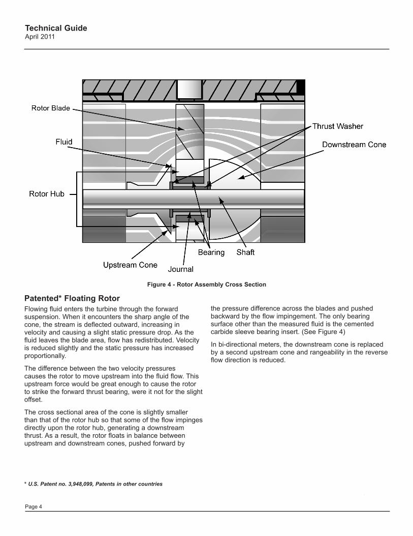
Patented* Floating RotorFlowing fluid enters the turbine through the forward suspension. When it encounters the sharp angle of the cone, the stream is deflected outward, increasing in velocity and causing a slight static pressure drop. As the fluid leaves the blade area, flow has redistributed. Velocity is reduced slightly and the static pressure has increased proportionally.
The difference between the two velocity pressures causes the rotor to move upstream into the fluid flow. This upstream force would be great enough to cause the rotor to strike the forward thrust bearing, were it not for the slight offset.
The cross sectional area of the cone is slightly smaller than that of the rotor hub so that some of the flow impinges directly upon the rotor hub, generating a downstream thrust. As a result, the rotor floats in balance between upstream and downstream cones, pushed forward by
* U.S. Patent no. 3,948,099, Patents in other countries
Figure 4 - Rotor Assembly Cross Section
the pressure difference across the blades and pushed backward by the flow impingement. The only bearing surface other than the measured fluid is the cemented carbide sleeve bearing insert. (See Figure 4)
In bi-directional meters, the downstream cone is replaced by a second upstream cone and rangeability in the reverse flow direction is reduced.
Technical GuideApril 2011
Page 5
Surge And Pressure Relief Valves
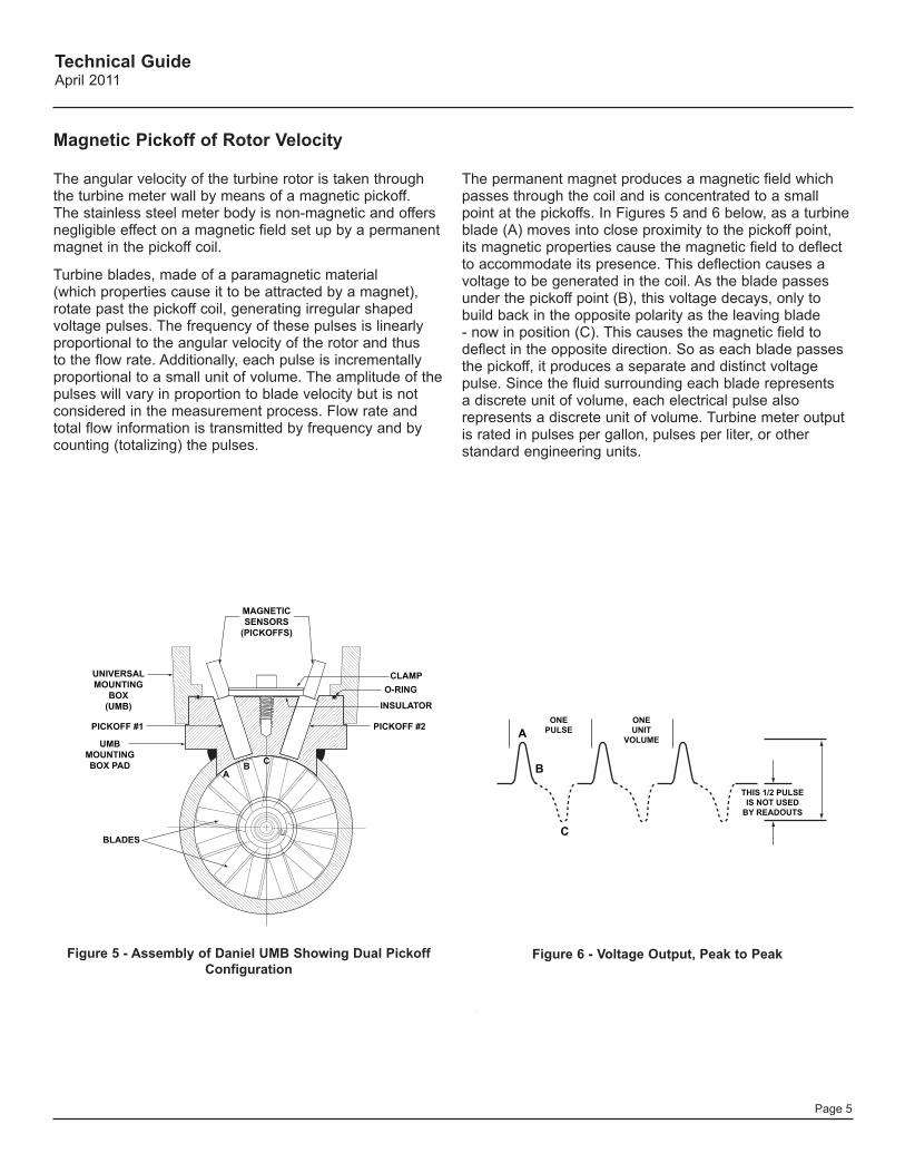
The angular velocity of the turbine rotor is taken through the turbine meter wall by means of a magnetic pickoff. The stainless steel meter body is non-magnetic and offers negligible effect on a magnetic field set up by a permanent magnet in the pickoff coil.
Turbine blades, made of a paramagnetic material (which properties cause it to be attracted by a magnet), rotate past the pickoff coil, generating irregular shaped voltage pulses. The frequency of these pulses is linearly proportional to the angular velocity of the rotor and thus to the flow rate. Additionally, each pulse is incrementally proportional to a small unit of volume. The amplitude of the pulses will vary in proportion to blade velocity but is not considered in the measurement process. Flow rate and total flow information is transmitted by frequency and by counting (totalizing) the pulses.
MAGNETICSENSORS
(PICKOFFS)
CLAMPO-RING
BLADES
PICKOFF #1 PICKOFF #2
INSULATOR
UNIVERSALMOUNTING
BOX(UMB)
UMBMOUNTINGBOX PAD
THIS 1/2 PULSEIS NOT USED
BY READOUTS
AB C
AONE
PULSE
B
C
ONEUNIT
VOLUME
MAGNETICSENSORS
(PICKOFFS)
CLAMPO-RING
BLADES
PICKOFF #1 PICKOFF #2
INSULATOR
UNIVERSALMOUNTING
BOX(UMB)
UMBMOUNTINGBOX PAD
THIS 1/2 PULSEIS NOT USED
BY READOUTS
AB C
AONE
PULSE
B
C
ONEUNIT
VOLUME
Figure 5 - Assembly of Daniel UMB Showing Dual Pickoff Configuration
Figure 6 - Voltage Output, Peak to Peak
The permanent magnet produces a magnetic field which passes through the coil and is concentrated to a small point at the pickoffs. In Figures 5 and 6 below, as a turbine blade (A) moves into close proximity to the pickoff point, its magnetic properties cause the magnetic field to deflect to accommodate its presence. This deflection causes a voltage to be generated in the coil. As the blade passes under the pickoff point (B), this voltage decays, only to build back in the opposite polarity as the leaving blade - now in position (C). This causes the magnetic field to deflect in the opposite direction. So as each blade passes the pickoff, it produces a separate and distinct voltage pulse. Since the fluid surrounding each blade represents a discrete unit of volume, each electrical pulse also represents a discrete unit of volume. Turbine meter output is rated in pulses per gallon, pulses per liter, or other standard engineering units.
Magnetic Pickoff of Rotor Velocity
Technical GuideApril 2011
Page 6
The primary differences in turbine meter technology are in the design of the rotor and bearings.
The rotor is an assembly of up to twelve (in some designs this number is greater) blades locked into a hub, which rotates on a bearing or bearings. For light liquid applications that require viscosities of 5cSt or less, and specific gravities of less than 0.75, the rotor does not normally need a rim (sometimes referred to as a shroud). For measuring the more viscous liquids and in larger size turbine meters (i.e. 8” and above) a rim is fitted to ensure sufficient rigidity in the rotor. A rim also offers the advantage of higher pulse resolution; with a bladed rotor the number of pulses per revolution is limited to the number of blades, and in a rimmed rotor the number of pulses per revolution corresponds to the number of buttons or slots in the rim.
For intermittent duties on light, clean hydrocarbons that may be found at tank truck terminals, ball bearings may be used for a rotor bearing. Proper design of rotors with ball bearings will use two ball races and a short axle upon which the rotor is fitted. Where space is constrained the ball races may be fitted directly into the rotor hub. This design is particularly suited to low and varying flow rate applications, and is utilized on the Daniel Series 1200 Liquid Turbine Flow Meter, designed primarily for distribution applications such as load racks. In these installations, liquids handled are typically light, refined products.
Pipeline applications often require continuous operation at fixed flow rates. Here the design of the turbine meter must offer sufficient longevity to minimize maintenance intervals. In these applications, tungsten carbide journal bearings are used, which offer exceptional longevity. As tungsten carbide is extremely hard wearing, designs utilizing this sort of bearing are often applied to more demanding measurement applications, such as crude oil.
It should be noted here that the limitations on viscosity are related to the rangeability of the turbine flow meter. As the viscosity of the measured liquid increases, the K-factor variations at different flow rates increase. Thus to maintain the linearity of the meter at the required level, as the viscosity of the measured liquid increases, the turn-down, or rangeability of the meter must be reduced. So for typical pipeline applications, where the flow meter will operate at just one flow rate (or a very limited range of flow rates) a turbine meter may be used to measure flows of high viscosity liquids. The Daniel Series 1500 Liquid Turbine Flow Meter is designed for pipeline applications, and is equipped with robust internals suited to continuous measurement of a wide range of liquids.
There may be a single hanger or hangers upstream and downstream of the rotor. In the Daniel Series 1200 Liquid Turbine Flow Meter there is a single upstream support for the rotor, and in the Daniel Series 1500 Liquid Turbine Flow Meter there are both upstream and downstream hangers.
Bearings may be either ball bearings or tungsten carbide journal bearings. Since ball bearings are used to provide improved performance on low flow rates and on clean product, they are a reliable, cost effective solution.
The Daniel Series 1200 Liquid Turbine Flow Meter deploys a cantilevered twin ball bearing design. Utilizing a rotating shaft on two ball bearing units, the Daniel Series 1200 Liquid Turbine Flow Meter is available in 1”, 1.5”, 2”, 3” and 4” line sizes. For more demanding applications, a tungsten carbide journal bearing assembly is available as an option.
Lightweight bladed rotors of this type mounted on ball bearings are particularly suited to the intermittent duty cycles typical in loading rack applications. The design application is limited to clean refined products. In the event that the turbine is used on slightly dirty products, the use of tungsten carbide journal bearings is recommended. Tungsten carbide bearings are extremely hard wearing and used in turbine meters on a range of applications from LPGs to crude oils.
Rimmed Rotors for Higher ResolutionIn the larger diameter Daniel Series 1500 Liquid Turbine Flow Meter (normally above 6” in line size), the resolution provided by a blade-type motor may be improved by the use of a rimmed (or shrouded) rotor. This construction is standard for Daniel meters of 8” and up. A lightweight stainless steel rim (or shroud) carries small paramagnetic buttons which provide a greater resolution of flow by generating more pulses per unit volume.
Daniel Series 1200 and 1500 Liquid Turbine Flow Meters are supplied with one Universal Mounting Box (UMB) as standard. This is attached to a boss, which in turn is attached to the meter body. This assembly may house two pickoffs, which are oriented such that their outputs are 90º electrically out of phase.
Turbine MeTer roTor and bearing design
Technical GuideApril 2011
Page 7
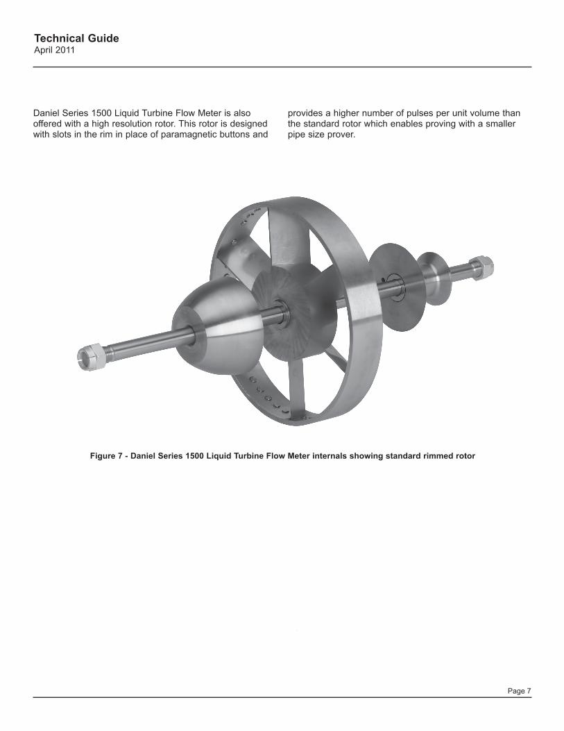
Figure 7 - Daniel Series 1500 Liquid Turbine Flow Meter internals showing standard rimmed rotor
Daniel Series 1500 Liquid Turbine Flow Meter is also offered with a high resolution rotor. This rotor is designed with slots in the rim in place of paramagnetic buttons and
provides a higher number of pulses per unit volume than the standard rotor which enables proving with a smaller pipe size prover.
Technical GuideApril 2011
Page 8
Flow Conditioning Plate
HangerHub
HangerBlades
Thrust Washer
Shaft Sleeve
Rotor Assembly
with Bearing
OutletDiffuser
Cap
O-ring
UMB Housing
Pickoffs
Dual ChannelPre-amplifer
UMB Cover
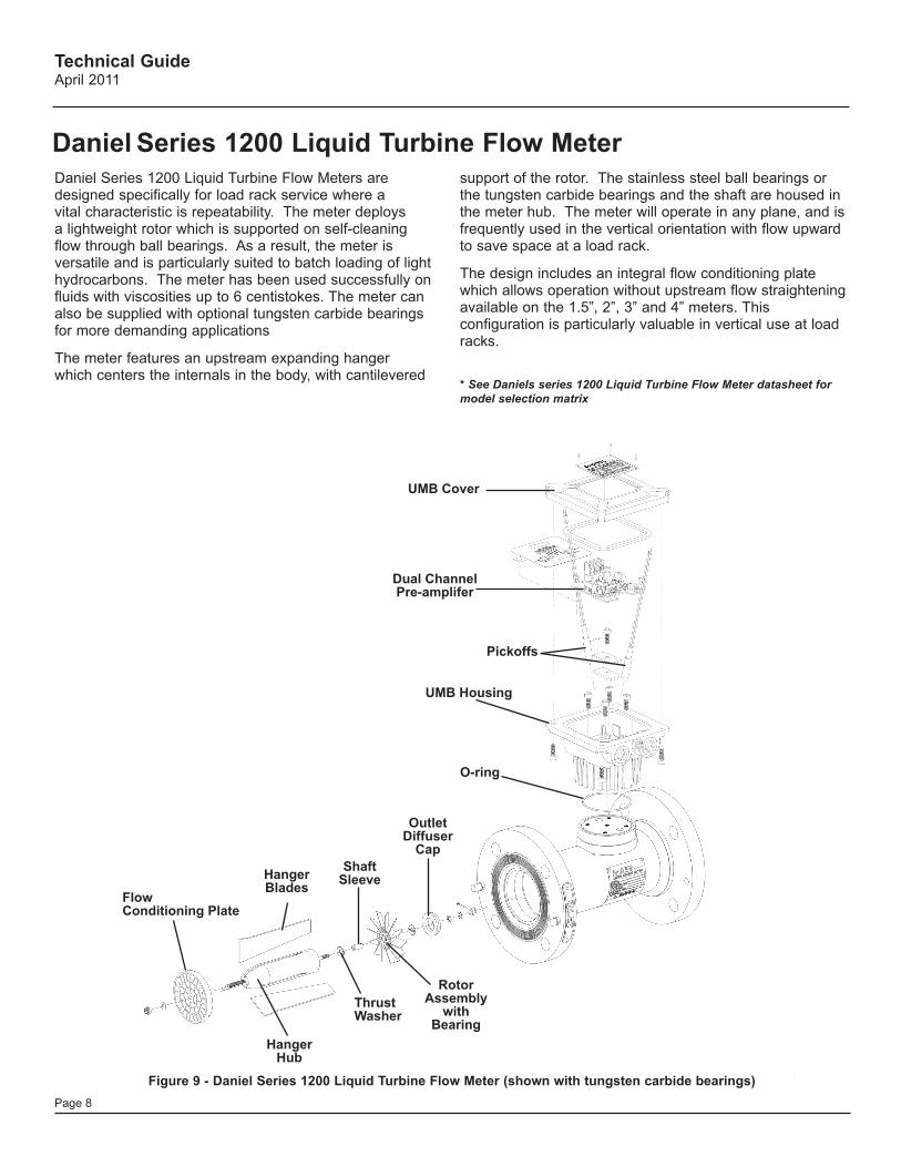
Figure 9 - Daniel Series 1200 Liquid Turbine Flow Meter (shown with tungsten carbide bearings)
Daniel Series 1200 Liquid Turbine Flow MeterDaniel Series 1200 Liquid Turbine Flow Meters are designed specifically for load rack service where a vital characteristic is repeatability. The meter deploys a lightweight rotor which is supported on self-cleaning flow through ball bearings. As a result, the meter is versatile and is particularly suited to batch loading of light hydrocarbons. The meter has been used successfully on fluids with viscosities up to 6 centistokes. The meter can also be supplied with optional tungsten carbide bearings for more demanding applications
The meter features an upstream expanding hanger which centers the internals in the body, with cantilevered
support of the rotor. The stainless steel ball bearings or the tungsten carbide bearings and the shaft are housed in the meter hub. The meter will operate in any plane, and is frequently used in the vertical orientation with flow upward to save space at a load rack.
The design includes an integral flow conditioning plate which allows operation without upstream flow straightening available on the 1.5”, 2”, 3” and 4” meters. This configuration is particularly valuable in vertical use at load racks.
* See Daniels series 1200 Liquid Turbine Flow Meter datasheet for model selection matrix
Technical GuideApril 2011
Page 9
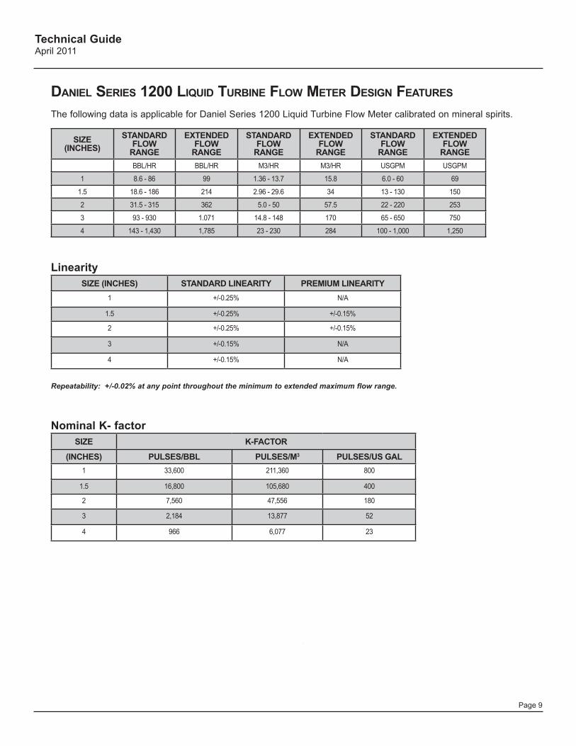
daniel series 1200 liquid Turbine Flow MeTer design FeaTures
The following data is applicable for Daniel Series 1200 Liquid Turbine Flow Meter calibrated on mineral spirits.
SIZE (INCHES)
STANDARD FLOW
RANGE
EXTENDED FLOW
RANGE
STANDARD FLOW
RANGE
EXTENDED FLOW
RANGE
STANDARD FLOW
RANGE
EXTENDED FLOW
RANGEBBL/HR BBL/HR M3/HR M3/HR USGPM USGPM
1 8.6 - 86 99 1.36 - 13.7 15.8 6.0 - 60 69
1.5 18.6 - 186 214 2.96 - 29.6 34 13 - 130 150
2 31.5 - 315 362 5.0 - 50 57.5 22 - 220 253
3 93 - 930 1.071 14.8 - 148 170 65 - 650 750
4 143 - 1,430 1,785 23 - 230 284 100 - 1,000 1,250
LinearitySIZE (INCHES) STANDARD LINEARITY PREMIUM LINEARITY
1 +/-0.25% N/A
1.5 +/-0.25% +/-0.15%
2 +/-0.25% +/-0.15%
3 +/-0.15% N/A
4 +/-0.15% N/A
Repeatability: +/-0.02% at any point throughout the minimum to extended maximum flow range.
Nominal K- factorSIZE K-FACTOR
(INCHES) PULSES/BBL PULSES/M3 PULSES/US GAL1 33,600 211,360 800
1.5 16,800 105,680 400
2 7,560 47,556 180
3 2,184 13,877 52
4 966 6,077 23
Technical GuideApril 2011
Page 10
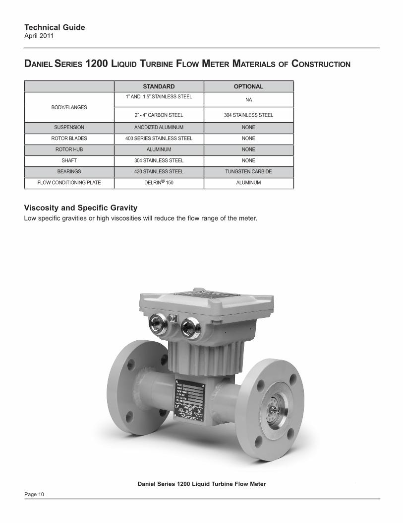
daniel series 1200 liquid Turbine Flow MeTer MaTerials oF ConsTruCTion
STANDARD OPTIONAL
BODY/FLANGES
1” AND 1.5” STAINLESS STEEL NA
2” - 4” CARBON STEEL 304 STAINLESS STEEL
SUSPENSION ANODIZED ALUMINUM NONE
ROTOR BLADES 400 SERIES STAINLESS STEEL NONE
ROTOR HUB ALUMINUM NONE
SHAFT 304 STAINLESS STEEL NONE
BEARINGS 430 STAINLESS STEEL TUNGSTEN CARBIDE
FLOW CONDITIONING PLATE DELRIN® 150 ALUMINUM
Viscosity and Specific GravityLow specific gravities or high viscosities will reduce the flow range of the meter.
Daniel Series 1200 Liquid Turbine Flow Meter
Technical GuideApril 2011
Page 11
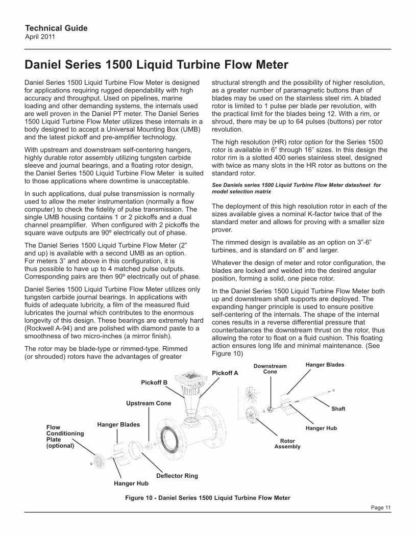
Daniel Series 1500 Liquid Turbine Flow Meter is designed for applications requiring rugged dependability with high accuracy and throughput. Used on pipelines, marine loading and other demanding systems, the internals used are well proven in the Daniel PT meter. The Daniel Series 1500 Liquid Turbine Flow Meter utilizes these internals in a body designed to accept a Universal Mounting Box (UMB) and the latest pickoff and pre-amplifier technology.
With upstream and downstream self-centering hangers, highly durable rotor assembly utilizing tungsten carbide sleeve and journal bearings, and a floating rotor design, the Daniel Series 1500 Liquid Turbine Flow Meter is suited to those applications where downtime is unacceptable.
In such applications, dual pulse transmission is normally used to allow the meter instrumentation (normally a flow computer) to check the fidelity of pulse transmission. The single UMB housing contains 1 or 2 pickoffs and a dual channel preamplifier. When configured with 2 pickoffs the square wave outputs are 90º electrically out of phase.
The Daniel Series 1500 Liquid Turbine Flow Meter (2” and up) is available with a second UMB as an option. For meters 3” and above in this configuration, it is thus possible to have up to 4 matched pulse outputs. Corresponding pairs are then 90º electrically out of phase.
Daniel Series 1500 Liquid Turbine Flow Meter utilizes only tungsten carbide journal bearings. In applications with fluids of adequate lubricity, a film of the measured fluid lubricates the journal which contributes to the enormous longevity of this design. These bearings are extremely hard (Rockwell A-94) and are polished with diamond paste to a smoothness of two micro-inches (a mirror finish).
The rotor may be blade-type or rimmed-type. Rimmed (or shrouded) rotors have the advantages of greater
Figure 10 - Daniel Series 1500 Liquid Turbine Flow Meter
Flow ConditioningPlate(optional)
Deflector RingHanger Hub
Hanger Blades
Upstream Cone
Pickoff APickoff B
Rotor Assembly
Downstream Cone
Hanger Hub
Hanger Blades
Shaft
structural strength and the possibility of higher resolution, as a greater number of paramagnetic buttons than of blades may be used on the stainless steel rim. A bladed rotor is limited to 1 pulse per blade per revolution, with the practical limit for the blades being 12. With a rim, or shroud, there may be up to 64 pulses (buttons) per rotor revolution.
The high resolution (HR) rotor option for the Series 1500 rotor is available in 6” through 16” sizes. In this design the rotor rim is a slotted 400 series stainless steel, designed with twice as many slots in the HR rotor as buttons on the standard rotor.
See Daniels series 1500 Liquid Turbine Flow Meter datasheet for model selection matrix
The deployment of this high resolution rotor in each of the sizes available gives a nominal K-factor twice that of the standard meter and allows for proving with a smaller size prover.
The rimmed design is available as an option on 3”-6” turbines, and is standard on 8” and larger.
Whatever the design of meter and rotor configuration, the blades are locked and welded into the desired angular position, forming a solid, one piece rotor.
In the Daniel Series 1500 Liquid Turbine Flow Meter both up and downstream shaft supports are deployed. The expanding hanger principle is used to ensure positive self-centering of the internals. The shape of the internal cones results in a reverse differential pressure that counterbalances the downstream thrust on the rotor, thus allowing the rotor to float on a fluid cushion. This floating action ensures long life and minimal maintenance. (See Figure 10)
Daniel Series 1500 Liquid Turbine Flow Meter
Technical GuideApril 2011
Page 12
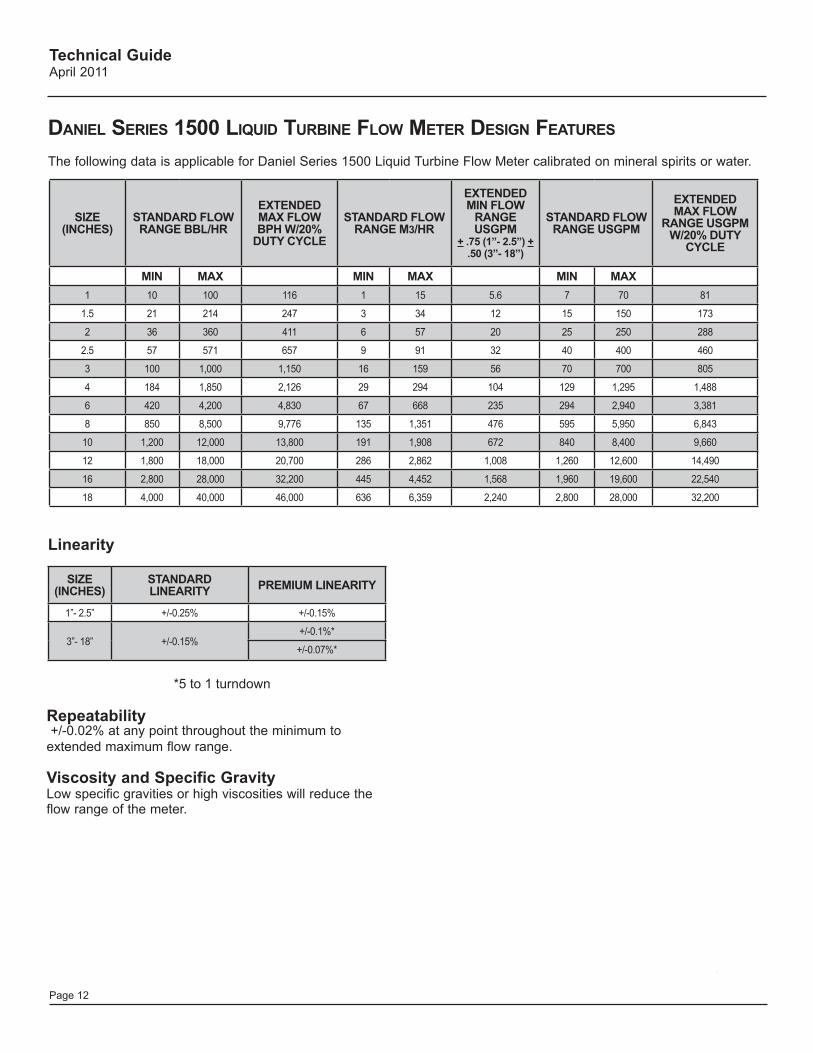
daniel series 1500 liquid Turbine Flow MeTer design FeaTures
The following data is applicable for Daniel Series 1500 Liquid Turbine Flow Meter calibrated on mineral spirits or water.
SIZE (INCHES)
STANDARD FLOW RANGE BBL/HR
EXTENDED MAX FLOW BPH W/20%
DUTY CYCLE
STANDARD FLOW RANGE M3/HR
EXTENDED MIN FLOW
RANGE USGPM
+ .75 (1”- 2.5”) + .50 (3”- 18”)
STANDARD FLOW RANGE USGPM
EXTENDED MAX FLOW
RANGE USGPM W/20% DUTY
CYCLE
MIN MAX MIN MAX MIN MAX1 10 100 116 1 15 5.6 7 70 81
1.5 21 214 247 3 34 12 15 150 173
2 36 360 411 6 57 20 25 250 288
2.5 57 571 657 9 91 32 40 400 460
3 100 1,000 1,150 16 159 56 70 700 805
4 184 1,850 2,126 29 294 104 129 1,295 1,488
6 420 4,200 4,830 67 668 235 294 2,940 3,381
8 850 8,500 9,776 135 1,351 476 595 5,950 6,843
10 1,200 12,000 13,800 191 1,908 672 840 8,400 9,660
12 1,800 18,000 20,700 286 2,862 1,008 1,260 12,600 14,490
16 2,800 28,000 32,200 445 4,452 1,568 1,960 19,600 22,540
18 4,000 40,000 46,000 636 6,359 2,240 2,800 28,000 32,200
*5 to 1 turndown
SIZE (INCHES)
STANDARD LINEARITY PREMIUM LINEARITY
1”- 2.5” +/-0.25% +/-0.15%
3”- 18” +/-0.15%+/-0.1%*
+/-0.07%*
Linearity
Repeatability +/-0.02% at any point throughout the minimum to extended maximum flow range.
Viscosity and Specific GravityLow specific gravities or high viscosities will reduce the flow range of the meter.
Technical GuideApril 2011
Page 13
ITEM STANDARD OPTIONAL OPTIONAL
METER BODY AND FLANGES304 STANDARD 1” AND 1.5” NA 316 SS
CS STANDARD 2” AND UP 304 SS 316 SS
SUSPENSION 304 SS 304 SS 316 SS
ROTOR BLADES (RIM TYPE) 304 SS 304 SS 316 SS
ROTOR BLADES (BLADES TYPE) 430 SS 430 SS NICKEL 200
SLEEVE BEARINGS TUNGSTEN CARBIDE TUNGSTEN CARBIDE TUNGSTEN CARBIDE
JOURNAL BEARINGS TUNGSTEN CARBIDE TUNGSTEN CARBIDE TUNGSTEN CARBIDE
ROTOR HUB 430 SS 430 SS 316 SS
ROTOR RIM 3” AND 4” 316 SS 316 SS 316 SS
ROTOR RIM 6” - 18” 304 SS 304 SS 316 SS
RIM BUTTONS HI MU 80 HI MU 80 HI MU 80
CONES 304 SS 304 SS 316 SS
SHAFT 316 SS 316 SS 316 SS
TOLERANCE RING 304 SS 304 SS 316 SS
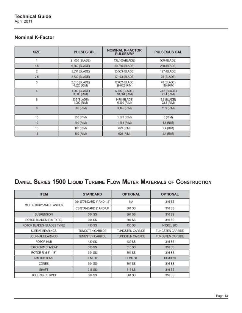
daniel series 1500 liquid Turbine Flow MeTer MaTerials oF ConsTruCTion
Nominal K-Factor
SIZE PULSES/BBL NOMINAL K-FACTORPULSES/M3 PULSES/US GAL
1 21,000 (BLADE) 132,100 (BLADE) 500 (BLADE)
1.5 9,660 (BLADE) 60,766 (BLADE) 230 (BLADE)
2 5,334 (BLADE) 33,553 (BLADE) 127 (BLADE)
2.5 2,730 (BLADE) 17,173 (BLADE) 75 (BLADE)
3 2,016 (BLADE)4,620 (RIM)
12,682 (BLADE) 29,062 (RIM)
48 (BLADE) 110 (RIM)
4 1,000 (BLADE) 3,000 (RIM)
6,290 (BLADE) 18,864 (RIM)
23.8 (BLADE) 71.4 (RIM)
6 235 (BLADE) 1,000 (RIM)
1478 (BLADE) 6,290 (RIM)
5.6 (BLADE) 23.8 (RIM)
8 500 (RIM) 3,145 (RIM) 11.9 (RIM)
10 250 (RIM) 1,572 (RIM) 6 (RIM)
12 200 (RIM) 1,258 (RIM) 4.8 (RIM)
16 100 (RIM) 629 (RIM) 2.4 (RIM)
18 100 (RIM) 629 (RIM) 2.4 (RIM)
Technical GuideApril 2011
Page 14
The flow ranges indicated in the previous tables show a nominal flow range -- with a turndown of 10:1 - at which the turbine will report measurement repeatable to the indicated specification based on measurement of clean liquids such as water (specific gravity 1, viscosity 1cSt) and mineral spirits (specific gravity 0.78, viscosity 1.8cSt).
Where liquids with properties outside of the range described by these liquids are to be measured, the meter flow range will be affected.
Extended flow rates on intermittent duty cycles are permitted and shown in the flow meter design features table on page 12. It should also be noted that the use of the meter in the extended flow range should be limited to a 20% duty cycle.
Liquid turbine meters are affected by changes in liquid density. When measuring liquids with specific gravities of 0.7 or less, the minimum flow rate of the meter must be increased to maintain the linearity of the meter within the required limits. In this application, the maximum flow rate may be increased to allow for greater rangeability.
It is vital that proper back pressure be maintained (refer to page 18 for the formula for determining required back pressure). Failure to do so may result in flashing and cavitation, which will cause over ranging of, and damage to, the meter.
Liquids with low specific gravities generally have high vapor pressures and high coefficients of thermal expansion. When measuring these liquids, it is extremely important that proper installation, measurement and proving practice be followed to provide stable temperatures and to negate the potential for poor measurement and possible system damage.
The data on the following page are for the Daniel Series 1500 Liquid Turbine Flow Meter, and similar effects will be observed in all design of turbine meters.
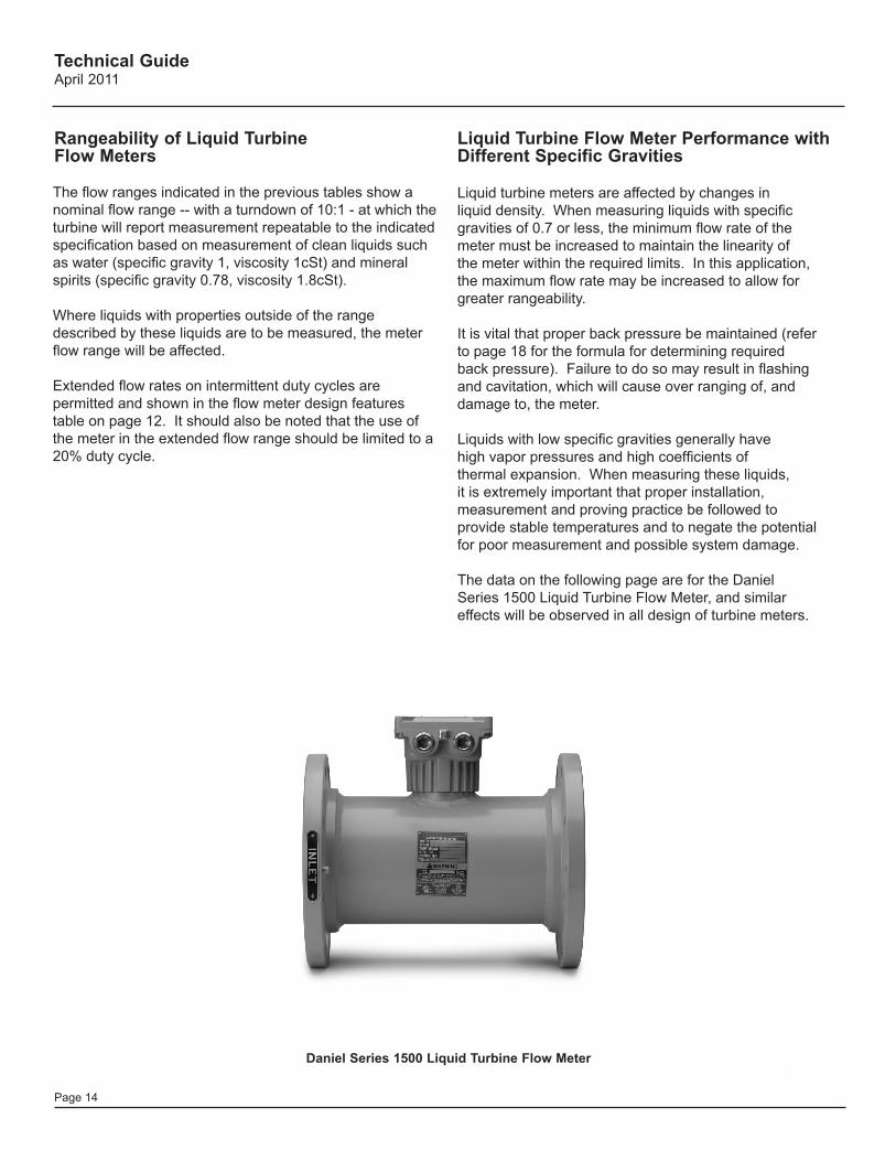
Liquid Turbine Flow Meter Performance with Different Specific Gravities
Rangeability of Liquid Turbine Flow Meters
Daniel Series 1500 Liquid Turbine Flow Meter
Technical GuideApril 2011
Page 15
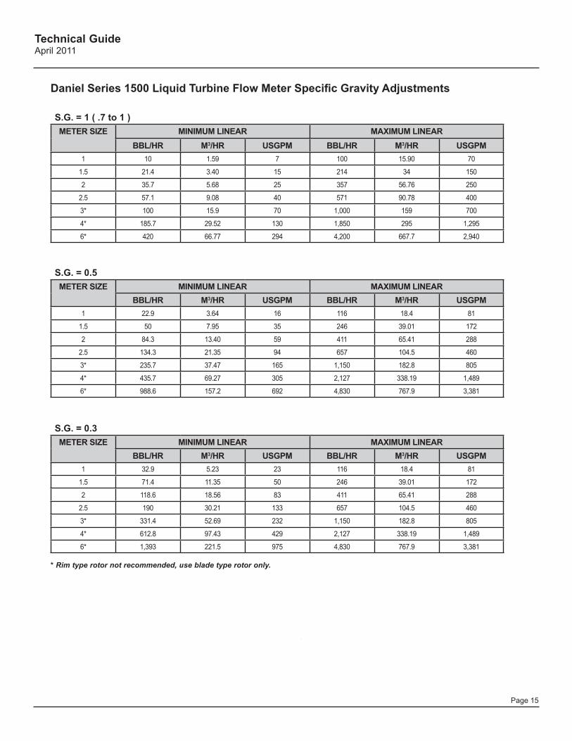
Daniel Series 1500 Liquid Turbine Flow Meter Specific Gravity Adjustments
S.G. = 1 ( .7 to 1 )METER SIZE MINIMUM LINEAR MAXIMUM LINEAR
BBL/HR M3/HR USGPM BBL/HR M3/HR USGPM1 10 1.59 7 100 15.90 70
1.5 21.4 3.40 15 214 34 150
2 35.7 5.68 25 357 56.76 250
2.5 57.1 9.08 40 571 90.78 400
3* 100 15.9 70 1,000 159 700
4* 185.7 29.52 130 1,850 295 1,295
6* 420 66.77 294 4,200 667.7 2,940
S.G. = 0.5METER SIZE MINIMUM LINEAR MAXIMUM LINEAR
BBL/HR M3/HR USGPM BBL/HR M3/HR USGPM1 22.9 3.64 16 116 18.4 81
1.5 50 7.95 35 246 39.01 172
2 84.3 13.40 59 411 65.41 288
2.5 134.3 21.35 94 657 104.5 460
3* 235.7 37.47 165 1,150 182.8 805
4* 435.7 69.27 305 2,127 338.19 1,489
6* 988.6 157.2 692 4,830 767.9 3,381
S.G. = 0.3METER SIZE MINIMUM LINEAR MAXIMUM LINEAR
BBL/HR M3/HR USGPM BBL/HR M3/HR USGPM1 32.9 5.23 23 116 18.4 81
1.5 71.4 11.35 50 246 39.01 172
2 118.6 18.56 83 411 65.41 288
2.5 190 30.21 133 657 104.5 460
3* 331.4 52.69 232 1,150 182.8 805
4* 612.8 97.43 429 2,127 338.19 1,489
6* 1,393 221.5 975 4,830 767.9 3,381
* Rim type rotor not recommended, use blade type rotor only.
Technical GuideApril 2011
Page 16
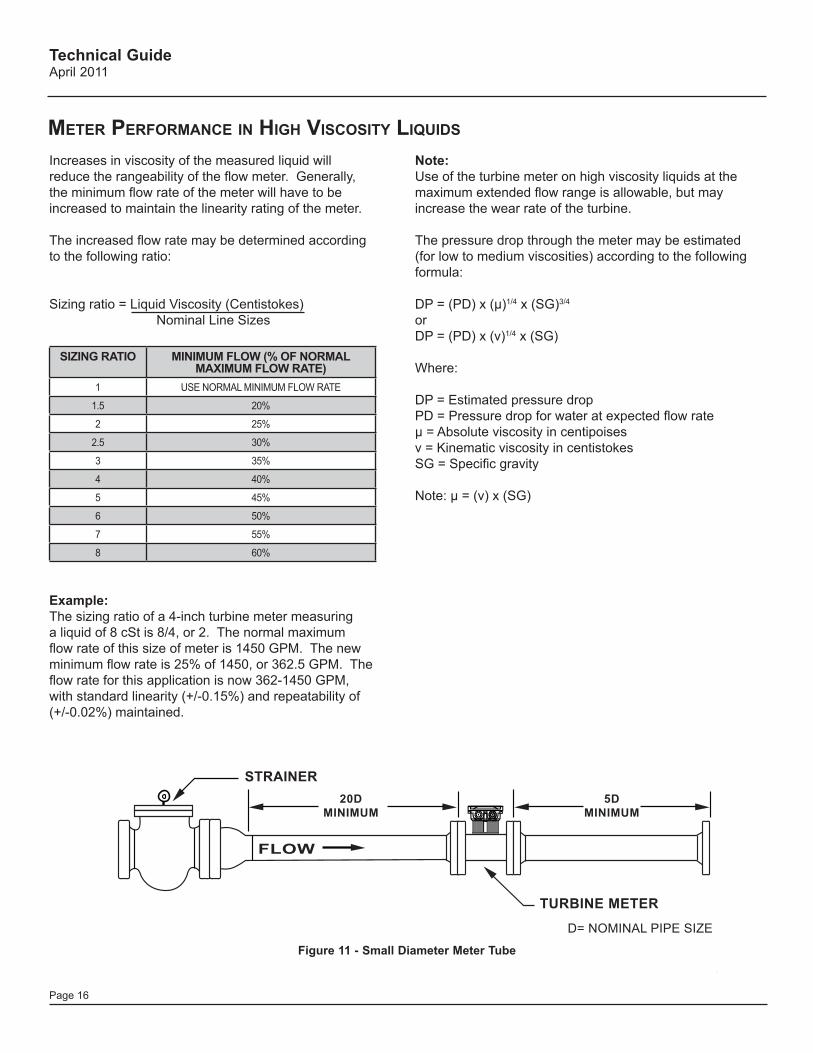
Increases in viscosity of the measured liquid will reduce the rangeability of the flow meter. Generally, the minimum flow rate of the meter will have to be increased to maintain the linearity rating of the meter.
The increased flow rate may be determined according to the following ratio:
Sizing ratio = Liquid Viscosity (Centistokes) Nominal Line Sizes
SIZING RATIO MINIMUM FLOW (% OF NORMAL MAXIMUM FLOW RATE)
1 USE NORMAL MINIMUM FLOW RATE
1.5 20%
2 25%
2.5 30%
3 35%
4 40%
5 45%
6 50%
7 55%
8 60%
Example:The sizing ratio of a 4-inch turbine meter measuring a liquid of 8 cSt is 8/4, or 2. The normal maximum flow rate of this size of meter is 1450 GPM. The new minimum flow rate is 25% of 1450, or 362.5 GPM. The flow rate for this application is now 362-1450 GPM, with standard linearity (+/-0.15%) and repeatability of (+/-0.02%) maintained.
Note: Use of the turbine meter on high viscosity liquids at the maximum extended flow range is allowable, but may increase the wear rate of the turbine.
The pressure drop through the meter may be estimated (for low to medium viscosities) according to the following formula:
DP = (PD) x (μ)1/4 x (SG)3/4
orDP = (PD) x (v)1/4 x (SG)
Where:
DP = Estimated pressure dropPD = Pressure drop for water at expected flow rateμ = Absolute viscosity in centipoisesv = Kinematic viscosity in centistokesSG = Specific gravity
Note: μ = (v) x (SG)
MeTer PerForManCe in high VisCosiTy liquids
Figure 11 - Small Diameter Meter Tube
STRAINER
TURBINE METER
D= NOMINAL PIPE SIZE
FLOW
20DMINIMUM
5DMINIMUM
Technical GuideApril 2011
Page 17
For a turbine meter to perform without increased uncertainty and in a repeatable and accurate manner, the flowing stream must be free of rotational components. The internal assembly supports of a turbine meter offer a slight straightening effect, but additional flow straightening is normally required.
Generally, upstream flow straightening is effected through the use of adequate upstream straightening sections, which often comprise a set of straightening vanes or a tube bundle. Guidance on this subject is offered in the API Manual of Petroleum Measurement Standards, Chapter 5, Section 3.
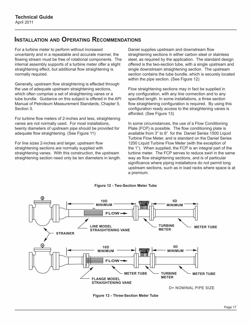
For turbine flow meters of 2-inches and less, straightening vanes are not normally used. For most installations, twenty diameters of upstream pipe should be provided for adequate flow straightening. (See Figure 11)
For line sizes 2-inches and larger, upstream flow straightening sections are normally supplied with straightening vanes. With this construction, the upstream straightening section need only be ten diameters in length.
Figure 12 - Two-Section Meter Tube
Figure 13 - Three-Section Meter Tube
Daniel supplies upstream and downstream flow straightening sections in either carbon steel or stainless steel, as required by the application. The standard design offered is the two-section tube, with a single upstream and single downstream straightening section. The upstream section contains the tube bundle, which is securely located within the pipe section. (See Figure 12)
Flow straightening sections may in fact be supplied in any configuration, with any line connection and to any specified length. In some installations, a three section flow straightening configuration is required. By using this configuration ready access to the straightening vanes is afforded. (See Figure 13)
In some circumstances, the use of a Flow Conditioning Plate (FCP) is possible. The flow conditioning plate is available from 3” to 6” for the Daniel Series 1500 Liquid Turbine Flow Meter, and is standard on the Daniel Series 1200 Liquid Turbine Flow Meter (with the exception of the 1”). When supplied, the FCP is an integral part of the turbine meter. The FCP serves to reduce swirl in the same way as flow straightening sections, and is of particular significance where piping installations do not permit long upstream sections, such as in load racks where space is at a premium.
TWO-SECTION METER TUBE
TURBINEMETER
D= NOMINAL PIPE SIZE
FLOW
10DMINIMUM
5DMINIMUM
METER TUBE
STRAINER
THREE-SECTION METER TUBE
TURBINEMETER
FLOW
10DMINIMUM
5DMINIMUM
METER TUBEFLANGE MODELSTRAIGHTENING VANE
LINE MODELSTRAIGHTENING VANE
METER TUBE
insTallaTion and oPeraTing reCoMMendaTions
Technical GuideApril 2011
Page 18
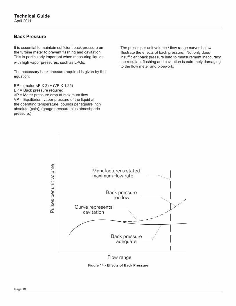
Figure 14 - Effects of Back Pressure
Back Pressure
It is essential to maintain sufficient back pressure on the turbine meter to prevent flashing and cavitation. This is particularly important when measuring liquids with high vapor pressures, such as LPGs.
The necessary back pressure required is given by the equation:
BP = (meter ∆P X 2) + (VP X 1.25)BP = Back pressure required∆P = Meter pressure drop at maximum flowVP = Equilibrium vapor pressure of the liquid at the operating temperature, pounds per square inch absolute (psia), (gauge pressure plus atmoshperic pressure.)
The pulses per unit volume / flow range curves below illustrate the effects of back pressure. Not only does insufficient back pressure lead to measurement inaccuracy, the resultant flashing and cavitation is extremely damaging to the flow meter and pipework.
Technical GuideApril 2011
Page 19
DUAL CHANNEL PREAMP TERMINAL IDENTIFICATION CUSTOMER CONNECTIONS
BLACK OR RED
PICKOFFPICKOFF
WHITE
WHITE
CHANNEL B CHANNEL A
BLACK OR RED
T U
P T
U O
B .
A H
C
T U
P T
U O
A .
A H
C
C D
V 0
3 O
T 0
1 +
N O
M M
O C
N O
M M
O C
TB1 1 2 3 4 5
2
1 2 1
TB2 TB3
J3 J4
J2
JUMPER POSITIONS JUMPER A B OUT J1-CHAN. A INPUT N/A 40mV. PP MIN N/A J1-CHAN. B INPUT N/A 40mV. PP MIN N/A J3-CHAN. A OUTPUT 5V.PULSE SUP. VOLT. PULSE (10-30 VDC) O.C. J4-CHAN. B OUTPUT 5V.PULSE SUP. VOLT. PULSE (10-30 VDC) O.C.
J1
PREAMP JUMPER CONFIGURATIONS
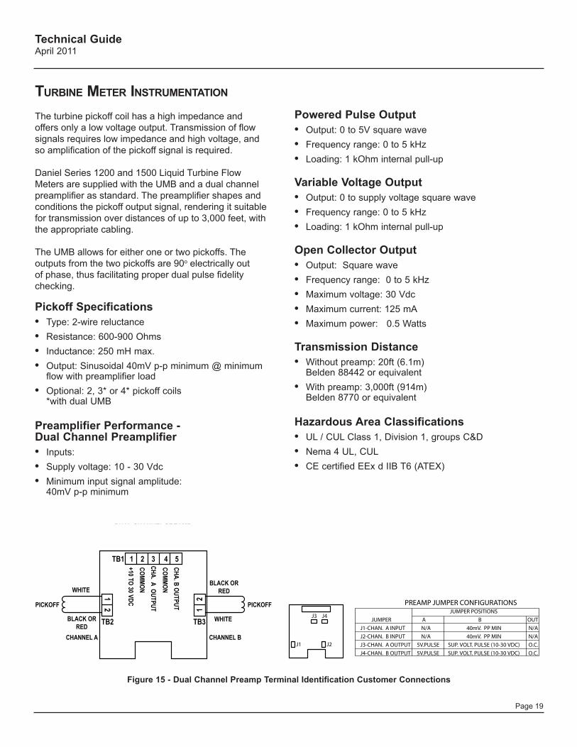
Turbine MeTer insTruMenTaTion
The turbine pickoff coil has a high impedance and offers only a low voltage output. Transmission of flow signals requires low impedance and high voltage, and so amplification of the pickoff signal is required.
Daniel Series 1200 and 1500 Liquid Turbine Flow Meters are supplied with the UMB and a dual channel preamplifier as standard. The preamplifier shapes and conditions the pickoff output signal, rendering it suitable for transmission over distances of up to 3,000 feet, with the appropriate cabling.
The UMB allows for either one or two pickoffs. The outputs from the two pickoffs are 90o electrically out of phase, thus facilitating proper dual pulse fidelity checking.
Pickoff Specifications• Type: 2-wire reluctance • Resistance: 600-900 Ohms • Inductance: 250 mH max. • Output: Sinusoidal 40mV p-p minimum @ minimum
flow with preamplifier load • Optional: 2, 3* or 4* pickoff coils
*with dual UMB
Preamplifier Performance - Dual Channel Preamplifier• Inputs: • Supply voltage: 10 - 30 Vdc• Minimum input signal amplitude:
40mV p-p minimum
Powered Pulse Output• Output: 0 to 5V square wave• Frequency range: 0 to 5 kHz• Loading: 1 kOhm internal pull-up
Variable Voltage Output• Output: 0 to supply voltage square wave• Frequency range: 0 to 5 kHz• Loading: 1 kOhm internal pull-up
Open Collector Output• Output: Square wave • Frequency range: 0 to 5 kHz• Maximum voltage: 30 Vdc• Maximum current: 125 mA• Maximum power: 0.5 Watts
Transmission Distance• Without preamp: 20ft (6.1m)
Belden 88442 or equivalent• With preamp: 3,000ft (914m)
Belden 8770 or equivalent
Hazardous Area Classifications• UL / CUL Class 1, Division 1, groups C&D• Nema 4 UL, CUL• CE certified EEx d IIB T6 (ATEX)
DUAL CHANNEL PREAMPTERMINAL IDENTIFICATIONCUSTOMER CONNECTIONS
BLACK ORRED
PICKOFFPICKOFF
WHITE
WHITE
CHANNEL BCHANNEL A
BLACK ORRED
TU
PTU
O B .
AH
C
TU
PTU
O A
.A
HC
CD
V 03
OT
01+
NO
MM
OC
NO
MM
OC
TB1 1 2 3 4 5
2
1 2 1
TB2 TB3
J3 J4
J2
JUMPER POSITIONS
JUMPER A B OUT
J1-CHAN. A INPUT N/A 40mV. PP MIN N/A
J2-CHAN. B INPUT N/A 40mV. PP MIN N/A
J3-CHAN. A OUTPUT 5V.PULSE SUP. VOLT. PULSE (10-30 VDC) O.C.
J4-CHAN. B OUTPUT 5V.PULSE SUP. VOLT. PULSE (10-30 VDC) O.C.
J1
PREAMP JUMPER CONFIGURATIONS
Figure 15 - Dual Channel Preamp Terminal Identification Customer Connections

This page intentionally left blank

This page intentionally left blankThis page intentionally left blank
Daniel Measurement and Control, Inc. ("Daniel") is a wholly owned subsidiary of Emerson Electric Co., and a division of Emerson Process Management. The Daniel name and logo are registered trademarks of Daniel Industries, Inc. The Emerson logo is a registered trademark and service mark of Emerson Electric Co. All other trademarks are the property of their respective companies. The contents of this publication are presented for informational purposes only, and while every effort has been made to ensure their accuracy, they are not to be construed as warranties or guarantees, express or implied, regarding the products or services described herein or their use or applicability. All sales are governed by Daniel's terms and conditions which are available upon request. We reserve the right to modify or improve the designs or specifications of such products at any time. Daniel does not assume responsibility for the selection, use or maintenance of any product. Responsibility for proper selection, use and maintenance of any Daniel product remains solely with the purchaser and end-user. The Daniel Liquid Ultrasonic Meter is protected by U.S. and international patents and patents pending.
2011 Daniel Measurement and Control, Inc. All Rights Reserved. Unauthorized duplication in whole or in part is prohibited. Printed in the USA. DAN-LIQ-Turbine-Meter-TG-0411
Emerson Process ManagementDaniel Measurement and Control, Inc.www.daniel.com
North America / Latin America:HeadquartersUSA - Houston, TexasT +1.713.467.6000F +1.713.827.3880USA Toll Free 1.888.FLOW.001
Europe: Stirling, Scotland, UK T +44.1786.433400F +44.1786.433401
Middle East, Africa: Dubai, UAET +971.4.811.8100F +971.4.883.5312
Asia Pacific: Singapore T +65.6777.8211F +65.6770.8001
TM