Embed Size (px)
Citation preview

VersionNumber:SURE950000REV.D
FactoryAddress:No.12OuterRingIndustrialPark,ZhongBeiIndustrialPark
(NorthernArea),XiqingDistrict,Tianjin,China
Room502,Gate1,BuildingB6,HaiTaiFaZhanWuDao,HaiTai
InnovationBase,XiqingDistrict,Tianjin,China
Telephone:+86-22-23732936/27984345.Ext:8043/8401
Email:[email protected]
OfficeAddress:
TianjinSureInstrumentScience&TechnologyCo.,Ltd
Website:www.suremeter.comSubjecttochangewithoutnoticeAllRightsReservedbyTianjinSureInstrument
www.suremeter.com
OperationManual
Gas Turbine Flow Meter Model: LWQ
GasTurbineFlowMeter
21
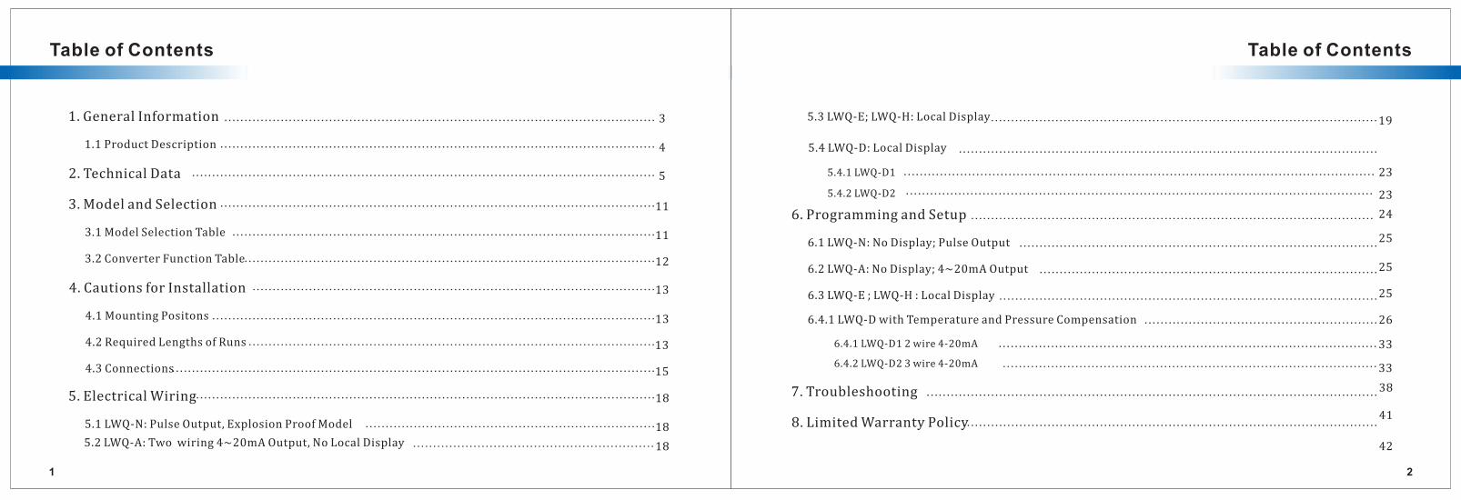
Table of Contents Table of Contents
1.GeneralInformation
1.1ProductDescription
2.TechnicalData
3.ModelandSelection
3.1ModelSelectionTable
3.2ConverterFunctionTable
4.CautionsforInstallation
4.1MountingPositons
4.2RequiredLengthsofRuns
4.3Connections
5.ElectricalWiring
3
4
5
11
11
12
13
13
13
15
18
...........................................................................................................
............................................................................................................
...................................................................................................................
............................................................................................................
.........................................................................................................
......................................................................................................
....................................................................................................
..............................................................................................................
.....................................................................................................
........................................................................................................................
...................................................................................................................
5.2LWQ-A:Twowiring4~20mAOutput,NoLocalDisplay 18............................................................
5.3LWQ-E;LWQ-H:LocalDisplay 19................................................................................................
5.1LWQ-N:PulseOutput,ExplosionProofModel 18........................................................................
23
25
25
25
26
33
38
41
42
33
23
246.ProgrammingandSetup
6.1LWQ-N:NoDisplay;PulseOutput
6.2LWQ-A:NoDisplay;4~20mAOutput
6.3LWQ-E;LWQ-H:LocalDisplay
6.4.1LWQ-D12wire4-20mA
6.4.2LWQ-D23wire4-20mA
7.Troubleshooting
8.LimitedWarrantyPolicy
....................................................................................................
.........................................................................................
..............................................................................................
....................................................................................
.............................................................................................
................................................................................................................
..............................................................................................
.......................................................................................................
5.4LWQ-D:LocalDisplay ........................................................................................................
6.4.1LWQ-DwithTemperatureandPressureCompensation ..........................................................
5.4.1LWQ-D1 .....................................................................................................................
5.4.2LWQ-D2 ....................................................................................................................
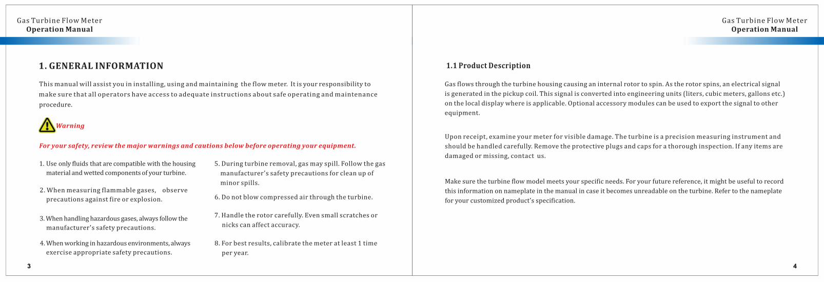
3.Whenhandlinghazardousgases,alwaysfollowthe
4.Whenworkinginhazardousenvironments,always
exerciseappropriatesafetyprecautions.
43 43
1.GENERALINFORMATION
Thismanualwillassistyouininstalling,usingandmaintainingtheflowmeter.Itisyourresponsibilityto
procedure.
Warning
makesurethatalloperatorshaveaccesstoadequateinstructionsaboutsafeoperatingandmaintenance
1.1ProductDescription
Foryoursafety,reviewthemajorwarningsandcautionsbelowbeforeoperatingyourequipment.
only compatible1.Use fluidsthatare withthehousing
materialandwettedcomponentsofyourturbine.
2.Whenmeasuringflammablegases, observe
precautionsagainstfireorexplosion.
manufacturer'ssafetyprecautions.
8.Forbestresults,calibratethemeteratleast1time
peryear.
GasTurbineFlowMeterOperationManual OperationManual
5.Duringturbineremoval,gasmayspill.Followthegas
manufacturer'ssafetyprecautionsforcleanupof
minorspills.
6.Donotblowcompressedairthroughtheturbine.
7.Handletherotorcarefully.Evensmallscratchesor
nickscanaffectaccuracy.
Gasflowsthroughtheturbinehousingcausinganinternalrotortospin.Astherotorspins,anelectricalsignal
isgeneratedinthepickupcoil.Thissignalisconvertedintoengineeringunits(liters,cubicmeters,gallonsetc.)
onthelocaldisplaywhereisapplicable.Optionalaccessorymodulescanbeusedtoexportthesignaltoother
equipment.
Uponreceipt,examineyourmeterforvisibledamage.Theturbineisaprecisionmeasuringinstrumentand
shouldbehandledcarefully.Removetheprotectiveplugsandcapsforathoroughinspection.Ifanyitemsare
damagedormissing,contactus.
Makesuretheturbineflowmodelmeetsyourspecificneeds.Foryourfuturereference,itmightbeusefultorecord
thisinformationonnameplateinthemanualincaseitbecomesunreadableontheturbine.Refertothenameplate
foryourcustomizedproduct'sspecification.
GasTurbineFlowMeter
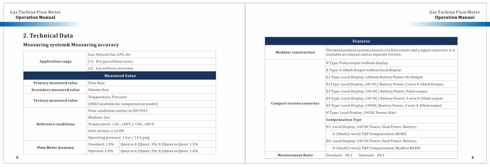
2.TechnicalData
Measuringsystem&Measuringaccuracy
65
OperationManual OperationManual
Applicationrange
Gas:NaturalGas,LPG,Air
(1)Drygaswithoutwater
(2)Gaswithoutcorrosion
MeasuredValue
Primarymeasuredvalue FlowRate
Secondarymeasuredvalue Volumeflow
TertiarymeasuredvalueTemperature;Pressure
(ONLYavailableforcompensationmodel)
Features
ModularconstructionThemeasurementsystemconsistsofaflowsensorandasignalconverter.Itisavailableascompactandasseparateversion.
Compactversionconverter
NType:Pulseoutputwithoutdisplay
AType:4-20mAOutputwithoutlocaldisplay
E1Type:LocalDisplay;LithiumBatteryPower;NoOutput
E2Type:LocalDisplay;24VDC/BatteryPower;2wire4-20mAOutput;
E3Type:LocalDisplay;24VDC/BatteryPower;Pulseoutput
E4Type:LocalDisplay;24VDC/BatteryPower;3wire0-20mAoutput
E5Type:LocalDisplay;24VDC/BatteryPower;3wire4-20mAoutput
HType:LocalDisplay;24VDCPower;Hart
CompensationType
D1:LocalDisplay;24VDCPower;DualPower:Battery;
4-20mA(2-wire);T&PCompensation;RS485
D2:LocalDisplay:24VDCPower;DualPower:Battery;
4-20mA(3-wire);T&PCompensation;ModbusRS485
MeasurementRatio Standard:10:1Optional:20:1
Referenceconditions
FlowconditionssimilartoISO9951
Medium:Gas
Temperature:+10...+30°C/+50...+86°F
Inletsection:≥10DN
Operatingpressure:1bar/14.5psig
FlowMeterAccuracyStandard:1.5% Qminto0.2Qmax:3%;0.2QmaxtoQmax:1.5%
Optional:1.0% Qminto0.2Qmax:2%;0.2QmaxtoQmax:1.0%
GasTurbineFlowMeterOperationManual OperationManual
GasTurbineFlowMeter
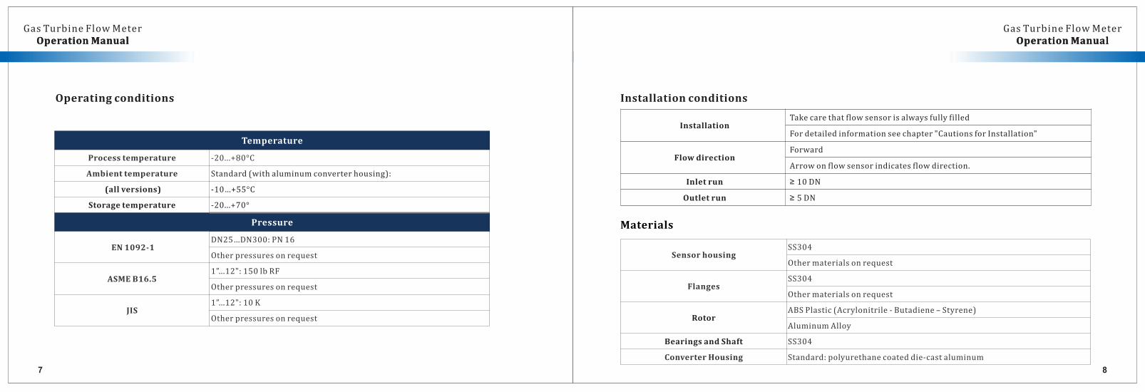
Installationconditions
Materials
87
OperationManual OperationManual
InstallationTakecarethatflowsensorisalwaysfullyfilled
Fordetailedinformationseechapter"CautionsforInstallation"
FlowdirectionForward
Arrowonflowsensorindicatesflowdirection.
Inletrun ≥ 10DN
Outletrun ≥ 5DN
Temperature
Processtemperature -20...+80°C
Ambienttemperature Standard(withaluminumconverterhousing):
(allversions) -10…+55°C
Storagetemperature -20...+70°
Pressure
EN1092-1DN25…DN300:PN16
Otherpressuresonrequest
ASMEB16.51”...12":150lbRF
Otherpressuresonrequest
JIS1”...12":10K
Otherpressuresonrequest
Operatingconditions
SensorhousingSS304
Othermaterialsonrequest
FlangesSS304
Othermaterialsonrequest
RotorABSPlastic(Acrylonitrile-Butadiene–Styrene)
AluminumAlloy
BearingsandShaft SS304
ConverterHousing Standard:polyurethanecoateddie-castaluminum
GasTurbineFlowMeterOperationManual OperationManual
GasTurbineFlowMeter
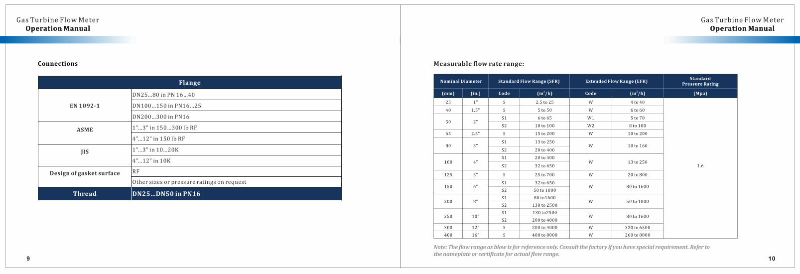
Connections Measurableflowraterange:
Note:Theflowrangeasblowisforreferenceonly.Consultthefactoryifyouhavespecialrequirement.Refertothenameplateorcertificateforactualflowrange.
9 10
OperationManual OperationManual
Flange
EN1092-1
DN25...80inPN16…40
DN100…150inPN16…25
DN200…300inPN16
ASME 1”…3"in150…300lbRF
4”…12”in150lbRF
JIS 1”…3”in10...20K
4”…12”in10K
Designofgasketsurface RF
Othersizesorpressureratingsonrequest
Thread DN25…DN50inPN16
NominalDiameter StandardFlowRange(SFR) ExtendedFlowRange(EFR)Standard
PressureRating
(mm) (in.) Code 3(m /h) Code 3(m /h) (Mpa)
25 1" S 2.5to25 W 4to40
1.6
40 1.5" S 5to50 W 6to60
50 2"S1 6to65 W1 5to70
S2 10to100 W2 8to100
65 2.5" S 15to200 W 10to200
80 3"S1 13to250
W 10to160S2 20to400
100 4"S1 20to400
W 13to250S2 32to650
125 5" S 25to700 W 20to800
150 6"S1 32to650
W 80to1600S2 50to1000
200 8"S1 80to1600
W 50to1000S2 130to2500
250 10"S1 130to2500
W 80to1600S2 200to4000
300 12" S 200to4000 W 320to6500
400 16" S 400to8000 W 260to8000
GasTurbineFlowMeterOperationManual OperationManual
GasTurbineFlowMeter
11 12
OperationManual OperationManual
3.M
odela
ndSelectio
n
3.1ModelS
electio
nTable
GasTurbineFlowMeterOperationManual OperationManual
GasTurbineFlowMeter
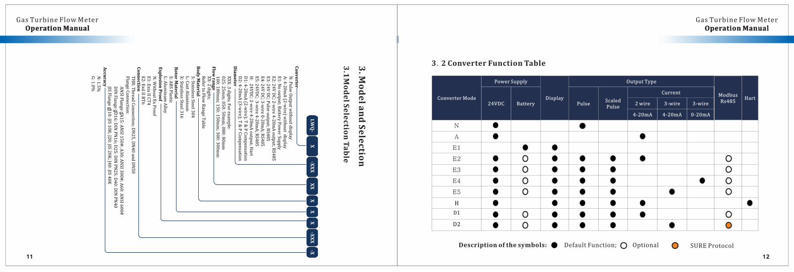
3.2ConverterFunctionTable
Descriptionofthesymbols:DefaultFunction;Optional SUREProtocol
ConverterMode
PowerSupply
Display
OutputType
ModbusRs485
Hart24VDC Battery Pulse
Scaled Pulse
Current
2wire 3-wire 3-wire
4-20mA 4-20mA 0-20mA
N
A
E1
E2
E3
E4
E5
H
D1
D2
13 14
OperationManual OperationManualGasTurbineFlowMeter
OperationManual OperationManualGasTurbineFlowMeter
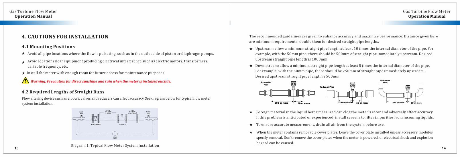
Warning:Precautionfordirectsunshineandrainwhenthemeterisinstalledoutside.
4.2RequiredLengthsofStraightRuns
Flowalteringdevicesuchaselbows,valvesandreducerscanaffectaccuracy.Seediagrambelowfortypicalflowmeter
systeminstallation.
4.CAUTIONSFORINSTALLATION
4.1MountingPositions
Installthemeterwithenoughroomforfutureaccessformaintenancepurposes★
Avoidlocationsnearequipmentproducingelectricalinterferencesuchaselectricmotors,transformers,
variablefrequency,etc.★
Avoidallpipelocationswheretheflowispulsating,suchasintheoutletsideofpistonordiaphragmpumps.★
Diagram1.TypicalFlowMeterSystemInstallation
Therecommendedguidelinesaregiventoenhanceaccuracyandmaximizeperformance.Distancegivenhere
areminimumrequirements;doublethemfordesiredstraightpipelengths.
Upstream:allowaminimumstraightpipelengthatleast10timestheinternaldiameterofthepipe.For
example,withthe50mmpipe,thereshouldbe500mmofstraightpipeimmediatelyupstream.Desired
upstreamstraightpipelengthis1000mm.
★
★ Downstream:allowaminimumstraightpipelengthatleast5timestheinternaldiameterofthepipe.
Forexample,withthe50mmpipe,thereshouldbe250mmofstraightpipeimmediatelyupstream.
Desiredupstreamstraightpipelengthis500mm.
★ Foreignmaterialintheliquidbeingmeasuredcanclogthemeter'srotorandadverselyaffectaccuracy.
Ifthisproblemisanticipatedorexperienced,installscreenstofilterimpuritiesfromincomingliquids.
★ Toensureaccuratemeasurement,drainallairfromthesystembeforeuse.
Whenthemetercontainsremovablecoverplates.Leavethecoverplateinstalledunlessaccessorymodules
specifyremoval.Don'tremovethecoverplateswhenthemeterispowered,orelectricalshockandexplosion
hazardcanbecaused.
★
1615
OperationManual OperationManualGasTurbineFlowMeter
OperationManual OperationManualGasTurbineFlowMeter
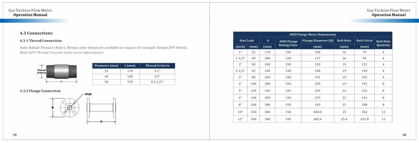
4.3Connections
4.3.1ThreadConnection
Note:DefaultThreadisMaleGThread,otherthreadareavailableonrequest.Forexample:FemaleNPTThread,
MaleNPTThread;Consultusformoreinformation
Diameter(mm) L(mm) ThreadCriteria
25 170 G2”
40 140 G2”
50 150 G2-1/2”
4.3.2FlangeConnection
ANSIFlangeMeterDimensions
SizeCode A ANSIFlangeRatingClass
FlangeDiameter(B) BoltHole BoltCircle BoltHoleQuantity
(inch) (mm) (mm) (mm) (mm) (mm)
1" 25 170 150 108 16 79 4
1-1/2" 40 200 150 127 16 99 4
2" 50 200 150 152 19 121 4
2-1/2" 65 240 150 180 19 140 4
3" 80 240 150 191 19 152 4
4" 100 300 150 229 19 191 8
5" 125 240 150 255 22 216 8
6" 150 450 150 279 22 241 8
8" 200 500 150 343 22 298 8
10" 250 500 150 460.4 25 362 12
12" 300 300 150 482.6 25.4 431.8 12
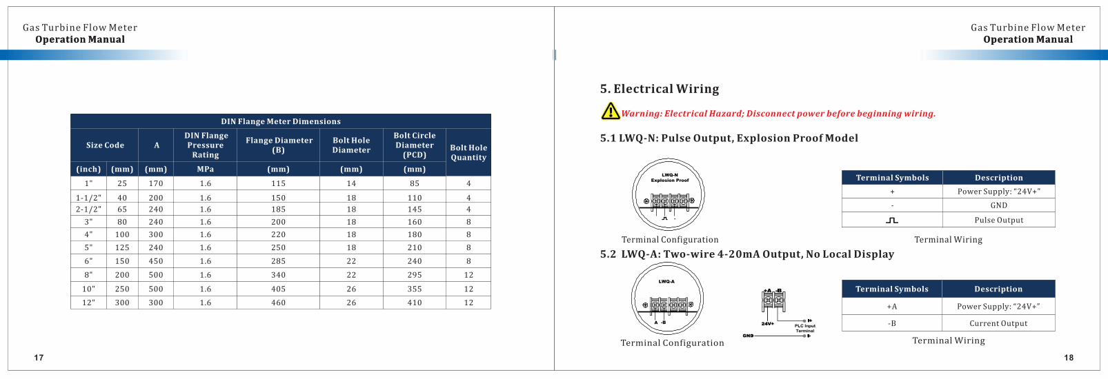
5.2LWQ-A:Two-wire4-20mAOutput,NoLocalDisplay
TerminalSymbols Description
+A PowerSupply:“24V+”
-B CurrentOutput
TerminalConfiguration TerminalWiring
A -B
LWQ-A
1817
OperationManual OperationManualGasTurbineFlowMeter
OperationManual OperationManualGasTurbineFlowMeter
DINFlangeMeterDimensions
SizeCode ADINFlangePressureRating
FlangeDiameter(B)
BoltHoleDiameter
BoltCircleDiameter(PCD)
BoltHoleQuantity
(inch) (mm) (mm) MPa (mm) (mm) (mm)
1" 25 170 1.6 115 14 85 4
1-1/2" 40 200 1.6 150 18 110 4
2-1/2" 65 240 1.6 185 18 145 4
3" 80 240 1.6 200 18 160 8
4" 100 300 1.6 220 18 180 8
5" 125 240 1.6 250 18 210 8
6" 150 450 1.6 285 22 240 8
8" 200 500 1.6 340 22 295 12
10" 250 500 1.6 405 26 355 12
12" 300 300 1.6 460 26 410 12
5. ElectricalWiring
Warning:ElectricalHazard;Disconnectpowerbeforebeginningwiring.
TerminalConfiguration TerminalWiring
5.1LWQ-N:PulseOutput,ExplosionProofModel
TerminalSymbols Description
+ PowerSupply:“24V+”
- GND
PulseOutput-
LWQ-NExplosion Proof
19 20
OperationManual OperationManualGasTurbineFlowMeter
OperationManual OperationManualGasTurbineFlowMeter
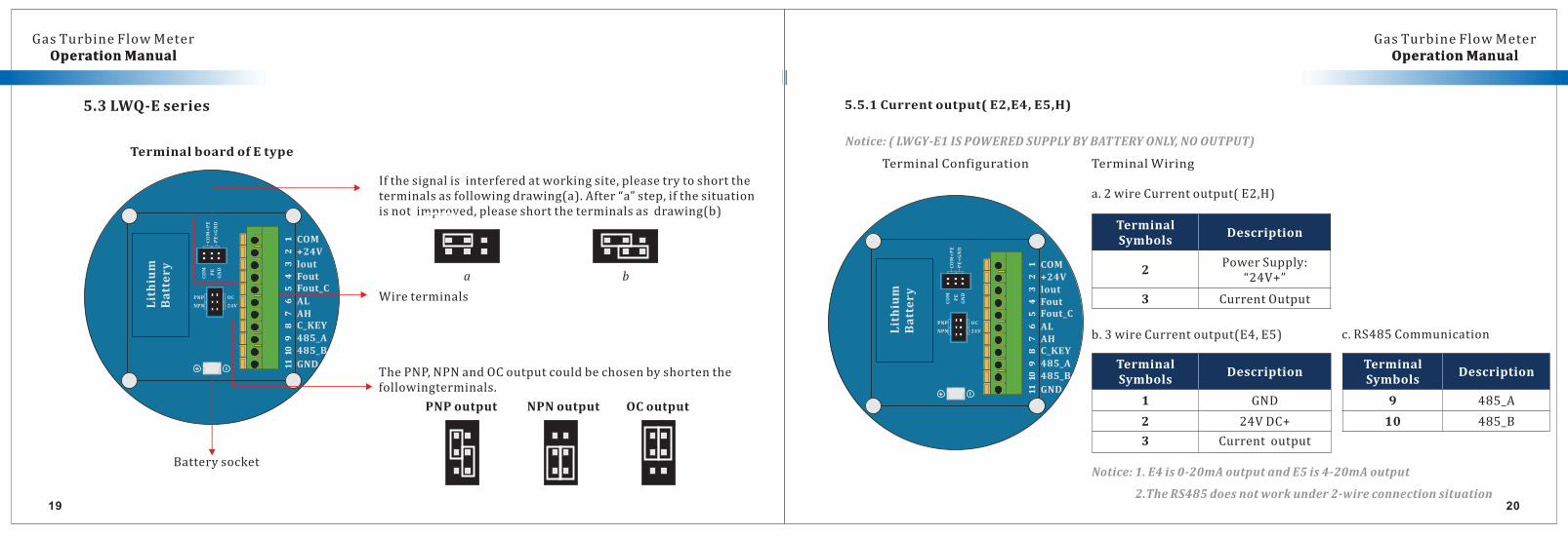
5.3LWQ-Eseries
TerminalboardofEtype
12
34
56
78
910
11
COM+24VloutFoutFout_C
ALAHC_KEY
485_A485_B
GND
COM
PE
GND
COM+PE
PE+GND
NPN
PNP OC
24VLithiu
m
Battery
Batterysocket
PNPoutput NPNoutput OCoutput
ThePNP,NPNandOCoutputcouldbechosenbyshortenthefollowingterminals.
Ifthesignalisinterferedatworkingsite,pleasetrytoshorttheterminalsasfollowingdrawing(a).After“a”step,ifthesituationisnotimproved,pleaseshorttheterminalsasdrawing(b)
a b
Wireterminals
5.5.1Currentoutput(E2,E4,E5,H)
TerminalConfiguration TerminalWiring
TerminalSymbols
Description
1 GND
2 24VDC+
3 Currentoutput
b. 3wireCurrentoutput(E4,E5)
TerminalSymbols
Description
2PowerSupply:
“24V+”
3 CurrentOutput
a. 2wireCurrentoutput(E2,H)
12
34
56
78
910
11
COM+24VloutFoutFout_C
ALAHC_KEY
485_A485_B
GND
COM
PE
GND
COM+PE
PE+GND
NPN
PNP OC
24VLithium
Battery
TerminalSymbols
Description
9 485_A
10 485_B
c. RS485Communication
Notice:(LWGY-E1ISPOWEREDSUPPLYBYBATTERYONLY,NOOUTPUT)
Notice:1.E4is0-20mAoutputandE5is4-20mAoutput
2.TheRS485doesnotworkunder2-wireconnectionsituation
21
OperationManual OperationManualGasTurbineFlowMeter
OperationManual OperationManualGasTurbineFlowMeter
22
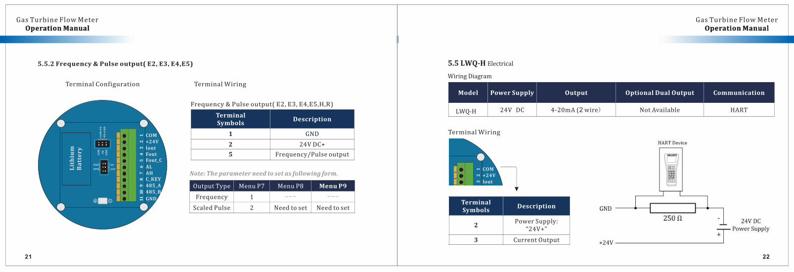
Frequency&Pulseoutput(E2,E3,E4,E5,H,R)
TerminalConfiguration
OutputType MenuP7 MenuP8 MenuP9
Frequency 1 --- ---
ScaledPulse 2 Needtoset Needtoset
TerminalSymbols
Description
1 GND
2 24VDC+
5 Frequency/Pulseoutput
TerminalWiring
12
34
56
78
910
11COM+24VloutFoutFout_C
ALAHC_KEY
485_A485_B
GND
COM
PE
GND
COM+PE
PE+GND
NPN
PNP OC
24VLithium
Battery
5.5.2Frequency&Pulseoutput(E2,E3,E4,E5)
Note:Theparameterneedtosetasfollowingform.
5.5LWQ-H ElectricalWiringDiagram
Function List for converter with local displayModel PowerSupply Output OptionalDualOutput Communication
LWQ-H 24V DC 4-20mA(2wire) NotAvailable HART
TerminalSymbols
Description
2PowerSupply:
“24V+”
3 CurrentOutput
12
3
COM+24Vlout
TerminalWiring
OperationManual OperationManualGasTurbineFlowMeter
OperationManual OperationManualGasTurbineFlowMeter
AH
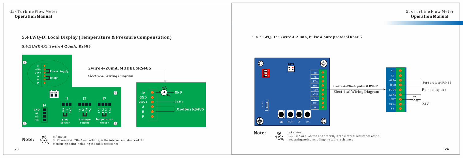
5.4.2LWQ-D2:3wire4-20mA,Pulse&SureprotocolRS485
/N
OFF
ĒÆĔ
AH
AL
AL
485A
485A
485B
485B
FOUT
FOUT
AGND
AGND
IOUT
IOUT
24V+
24V+
PE
PE
RIGHT UP ESC
12
3
ON
DP
-د
BAT1
3-wire4~20mA,pulse&RS485
AH
AL
485A
485B
FOUT
AGND
IOUT
24V+
PE
24V+
SureprotocolRS485
د -
mA
RL
Pulseoutput+ElectricalWiringDiagram
mAmeter0...20mAor4...20mAandotherR istheinternalresistanceoftheL
measuringpointincludingthecableresistanceد -
mA
RL
Note:
23 24
5.4LWQ-D:LocalDisplay(Temperature&PressureCompensation)
5.4.1LWQ-D1:2wire4-20mA,RS485
Battery
J1 J2 J3
J4
lo
GND
24V+
A
B
P
Power Supply
RS485
GND
A2A1
PIC
Pi
Vcc
GND
Po-
Po+
Pi+
Pi-
T11
T12
T21
T22
FlowSensor
PressureSensor
Temperature
Sensor
lo
GND
24V+
A
B
P
د -
mA
RL
GND
24V+
ModbusRS485
ElectricalWiringDiagram
2wire4-20mA,MODBUSRS485
mAmeter0...20mAor4...20mAandotherR istheinternalresistanceoftheL
measuringpointincludingthecableresistance
د -
mA
RL
Note:
25
OperationManual OperationManualGasTurbineFlowMeter
OperationManual OperationManualGasTurbineFlowMeter
26
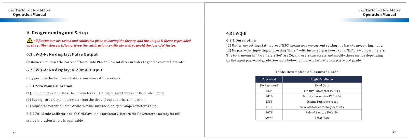
6.2.2FullScaleCalibration:It'sONLYavailableforfactory;Returntheflowmetertofactoryforfull
scalecalibrationwhereisapplicable.
6.1LWQ-N:Nodisplay;PulseOutput
CustomershouldsetthecorrectK-factorintoPLCorFlowtotalizerinordertogetthecorrectflowrate.
6.2LWQ-A:Nodisplay;4-20mAOutput
OnlyperformtheZeroPointCalibrationwhereit'snecessary.
Allflowmetersaretestedandcalibratedpriortoleavingthefactory,andtheuniqueK-factorisprovided
onthecalibrationcertificate.KeepthecalibrationcertificatewelltoavoidthelossofK-factor.
6. ProgrammingandSetup
6.2.1ZeroPointCalibration
(1)Shutoffthevaluewheretheflowmeterisinstalled,ensurethereisnoflowrateinpipe.
(2)Puthighaccuracyamperometerintothecircuitloopasseriesconnection.
(3)AdjustthepotentiometerW502tomakesurethedisplayonamperometeris4mA.
(1)Underanysettingstatus,press“ESC”meansnosavecurrentsettingandbacktomeasuringmode.
(2)Nopasswordinputtingorpressing“Enter”withincorrectpasswordcanONLYviewallparameters.
Thetotalmenusin“ParametersSet”are26,anduserscanaccessandmodifythesemenusdepending
ontheinputpasswordgrade.Seetablebelowformoreinformationonpasswordgrade.
Table.DescriptionofPasswordGrade
Password LoginPrivileges
NoPassword ReadOnly
1234 ModifyParameterP1-P14
1010 ModifyParameterP16-P26
5555 SettingTotalratereset
1111 Savealldataasfactorydefaults
5678 ReloadFactoryDefaults
9999 TotalFlow
6.3LWQ-E
6.3.1Description
28
OperationManual OperationManualGasTurbineFlowMeter
OperationManual OperationManualGasTurbineFlowMeter
27
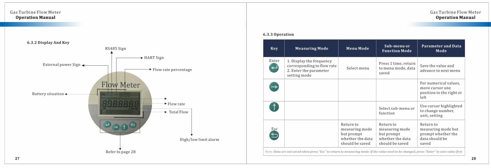
6.3.2DisplayAndKey
Refertopage28
TotalFlow
Batterysituation
ExternalpowerSign
RS485Sign
HARTSign
Flowrate
High/lowlimitalarm
Flowratepercentage
Key MeasuringMode MenuModeSub-menuor
FunctionModeParameterandData
Mode
Enter
SelectmenuSavethevalueandadvancetonextmenu
EscReturntomeasuringmodebutpromptwhetherthedatashouldbesaved
Returntomeasuringmodebutpromptwhetherthedatashouldbesaved
Note:Dataarenotsavedwhenpress“Esc”toreturntomeasuringmode.Ifthevalueneedtobechanged,press“Enter”tosavevaluefirst
6.3.3Operation
3029
OperationManual OperationManualGasTurbineFlowMeter
OperationManual OperationManualGasTurbineFlowMeter
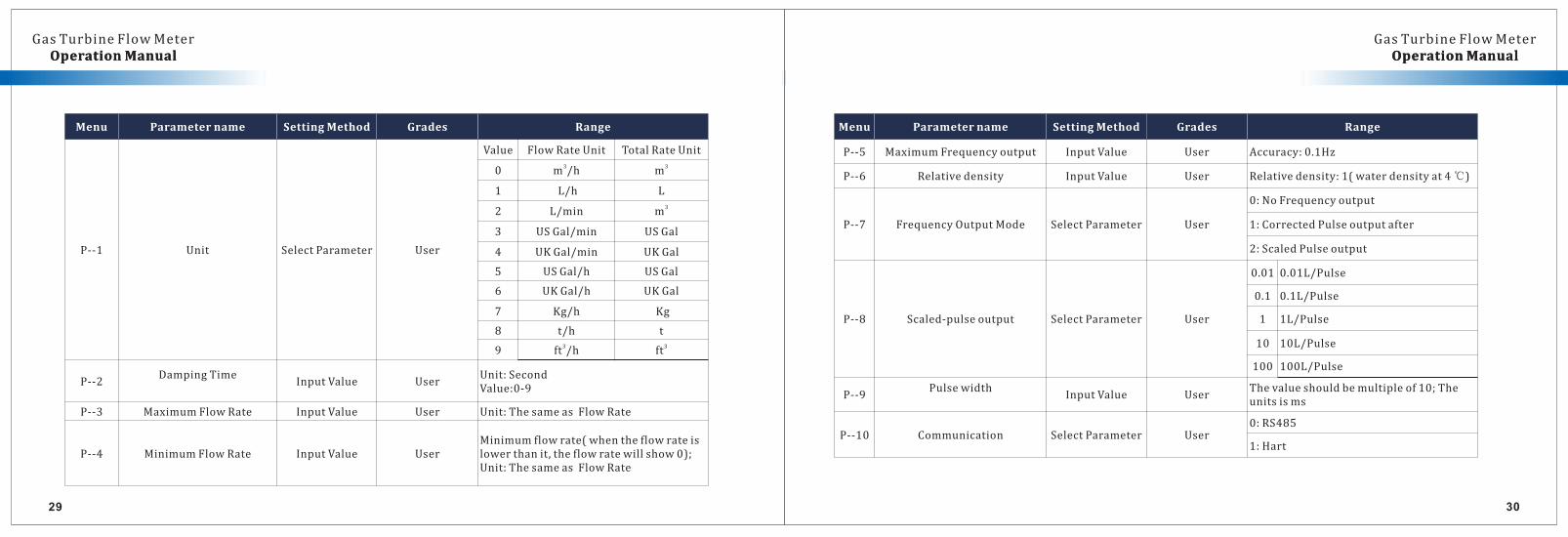
Menu Parametername SettingMethod Grades Range
P--1 Unit SelectParameter User
Value FlowRateUnit TotalRateUnit
0 3m /h 3m
1 L/h L
2 L/min 3m
3 USGal/min USGal
4 UKGal/min UKGal
5 USGal/h USGal
6 UKGal/h UKGal
7 Kg/h Kg
8 t/h t
9 3ft /h 3ft
P--2DampingTime
InputValue UserUnit:SecondValue:0-9
P--3 MaximumFlowRate InputValue User Unit:ThesameasFlowRate
P--4 MinimumFlowRate InputValue UserMinimumflowrate(whentheflowrateislowerthanit,theflowratewillshow0);Unit:ThesameasFlowRate
Menu Parametername SettingMethod Grades Range
P--5 MaximumFrequencyoutput InputValue User Accuracy:0.1Hz
P--6 Relativedensity InputValue User Relativedensity:1(waterdensityat4℃)
P--7 FrequencyOutputMode SelectParameter User
0:NoFrequencyoutput
1:CorrectedPulseoutputafter
2:ScaledPulseoutput
P--8 Scaled-pulseoutput SelectParameter User
0.01 0.01L/Pulse
0.1 0.1L/Pulse
1 1L/Pulse
10 10L/Pulse
100 100L/Pulse
P--9Pulsewidth
InputValue UserThevalueshouldbemultipleof10;Theunitsisms
P--10 Communication SelectParameter User0:RS485
1:Hart
3231
OperationManual OperationManualGasTurbineFlowMeter
OperationManual OperationManualGasTurbineFlowMeter
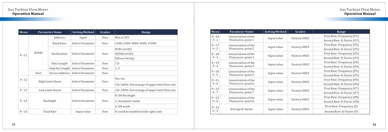
Menu ParameterName SettingMethod Grades Range
P--11RS485
Address: Input User Maxis255
BaudRate: SelectParameter User 1200,2400,4800,9600,19200
Verification: SelectParameter User
N(Noverify)
O(Oddverify)
E(EvenVerify)
DataLength SelectParameter User 7,8
Stopbitslength SelectParameter User 1,2
Hart DeviceAddress SelectParameter User
P--12HighLimitAlarm SelectParameter User
Yes:On
1%-100%:Percentageofupperlimitflowrate
P--13 LowLimitAlarm SelectParameter User 1%-100%:Percentageofupperlimitflowrate
P--14 Backlight SelectParameter User
0:OffBacklight
1:Automaticmode
2:ONmode
P--15 TotalRate Inputvalue User Itcouldbemodifiedwithrightcode
Menu ParameterName SettingMethod Grades Range
P--16F--1
LinearizationoftheFlowcurve:point1
Inputvalue FactoryONLYFirstRow:Frequency(P1)
SecondRow:K-Factor(P1)
P--17F--2
LinearizationoftheFlowcurve:point2
Inputvalue FactoryONLYFirstRow:Frequency(P2)
SecondRow:K-Factor(P2)
P--18F--3
LinearizationoftheFlowcurve:point3
Inputvalue FactoryONLYFirstRow:Frequency(P3)
SecondRow:K-Factor(P3)
P--19F--4
LinearizationoftheFlowcurve:point4
Inputvalue FactoryONLYFirstRow:Frequency(P4)
SecondRow:K-Factor(P4)
P--20F--5
LinearizationoftheFlowcurve:point5
Inputvalue FactoryONLYFirstRow:Frequency(P5)
SecondRow:K-Factor(P5)
P--21F--6
LinearizationoftheFlowcurve:point6
Inputvalue FactoryONLYFirstRow:Frequency(P6)
SecondRow:K-Factor(P6)
P--22F--7
LinearizationoftheFlowcurve:point7
Inputvalue FactoryONLYFirstRow:Frequency(P7)
SecondRow:K-Factor(P7)
P--23F--8
LinearizationoftheFlowcurve:point8
Inputvalue FactoryONLYFirstRow:Frequency(P8)
SecondRow:K-Factor(P8)
P--24F--9
AverageK-Factor Inputvalue FactoryONLYFirstRow:Frequency(P)
SecondRow:K-Factor(P)
3 3433
OperationManual OperationManualGasTurbineFlowMeter
OperationManual OperationManualGasTurbineFlowMeter
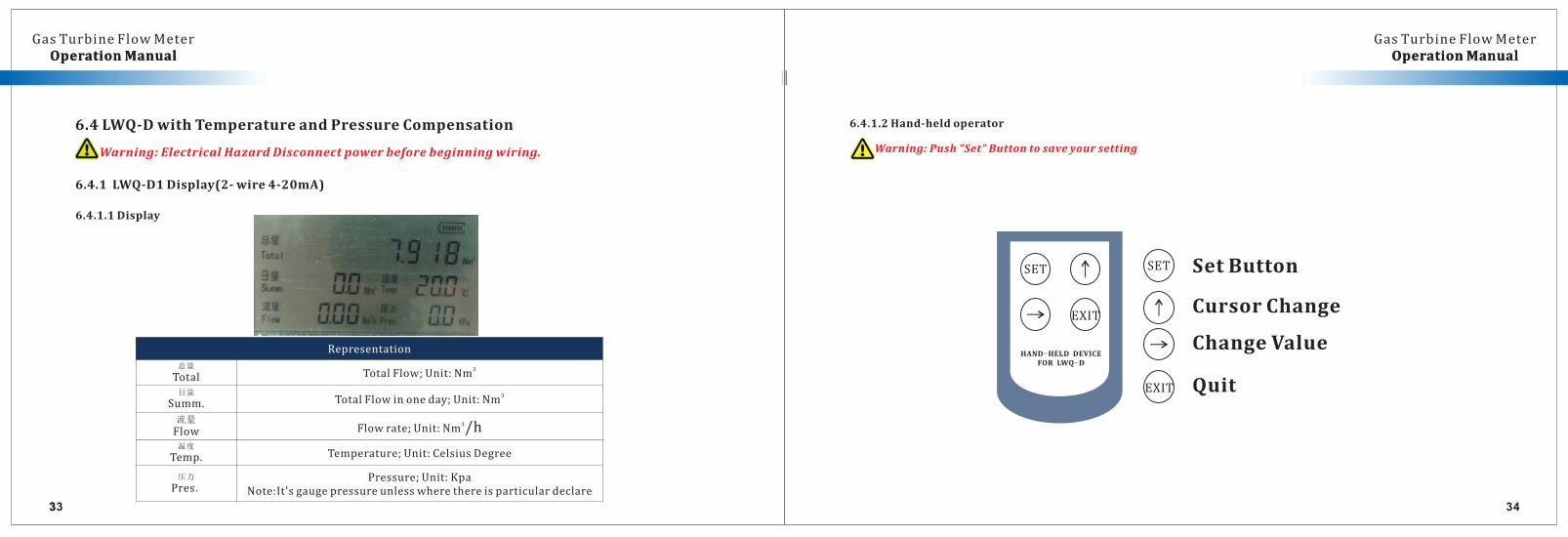
6.4LWQ-DwithTemperatureandPressureCompensation
Warning:ElectricalHazardDisconnectpowerbeforebeginningwiring.
6.4.1LWQ-D1Display(2-wire4-20mA)
6.4.1.1Display
Representation
总量
Total3
TotalFlow;Unit:Nm
日量
Summ.3
TotalFlowinoneday;Unit:Nm
流量
Flow3
Flowrate;Unit:Nm /h温度
Temp. Temperature;Unit:CelsiusDegree
压力
Pres.Pressure;Unit:Kpa
Note:It'sgaugepressureunlesswherethereisparticulardeclare
6.4.1.2Hand-heldoperator
Warning:Push“Set”Buttontosaveyoursetting
HAND-HELD DEVICEFOR LWQ-D
SET
EXIT
SetButton
CursorChange
ChangeValue
Quit
335
OperationManual OperationManualGasTurbineFlowMeter
OperationManual OperationManualGasTurbineFlowMeter
36
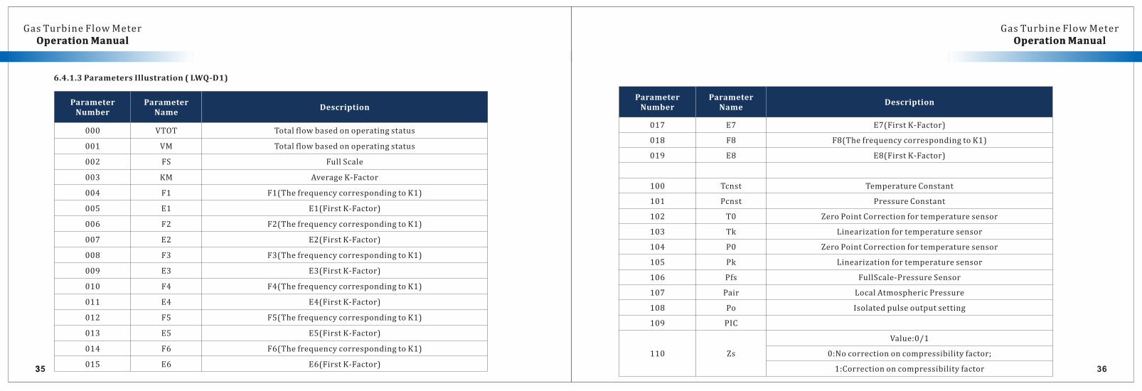
6.4.1.3ParametersIllustration(LWQ-D1)
337
OperationManual OperationManualGasTurbineFlowMeter
OperationManual OperationManualGasTurbineFlowMeter
38
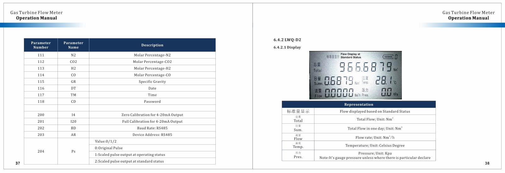
6.4.2LWQ-D2
6.4.2.1Display
339
OperationManual OperationManualGasTurbineFlowMeter
OperationManual OperationManualGasTurbineFlowMeter
40
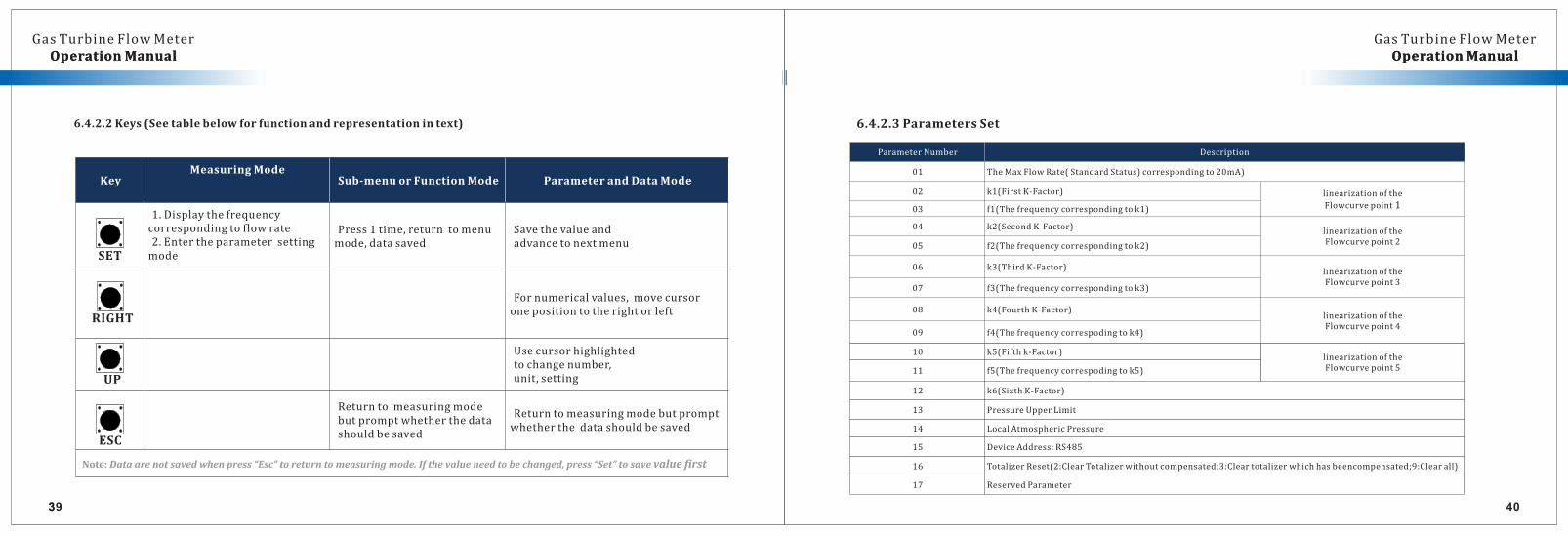
6.4.2.2Keys(Seetablebelowforfunctionandrepresentationintext)
ESC
SET
RIGHT
UP
KeyMeasuringMode
Sub-menuorFunctionMode ParameterandDataMode
1.Displaythefrequencycorrespondingtoflowrate2.Entertheparametersettingmode
Press1time,returntomenumode,datasaved
Savethevalueandadvancetonextmenu
Fornumericalvalues,movecursoronepositiontotherightorleft
Usecursorhighlightedtochangenumber,unit,setting
Returntomeasuringmodebutpromptwhetherthedatashouldbesaved
Returntomeasuringmodebutpromptwhetherthedatashouldbesaved
Note:Dataarenotsavedwhenpress“Esc”toreturntomeasuringmode.Ifthevalueneedtobechanged,press“Set”tosavevaluefirst
6.4.2.3ParametersSet
ParameterNumber Description
01 TheMaxFlowRate(StandardStatus)correspondingto20mA)
02 k1(FirstK-Factor) linearizationofthe
Flowcurvepoint103 f1(Thefrequencycorrespondingtok1)
04 k2(SecondK-Factor)linearizationoftheFlowcurvepoint205 f2(Thefrequencycorrespondingtok2)
06 k3(ThirdK-Factor)linearizationoftheFlowcurvepoint3
07 f3(Thefrequencycorrespondingtok3)
08 k4(FourthK-Factor)linearizationoftheFlowcurvepoint4
09 f4(Thefrequencycorrespodingtok4)
10 k5(Fifthk-Factor)linearizationoftheFlowcurvepoint511 f5(Thefrequencycorrespodingtok5)
12 k6(SixthK-Factor)
13 PressureUpperLimit
14 LocalAtmosphericPressure
15 DeviceAddress:RS485
16 TotalizerReset(2:ClearTotalizerwithoutcompensated;3:Cleartotalizerwhichhasbeencompensated;9:Clearall)
17 ReservedParameter
OperationManual OperationManual
4241
GasTurbineFlowMeterOperationManual OperationManual
GasTurbineFlowMeter
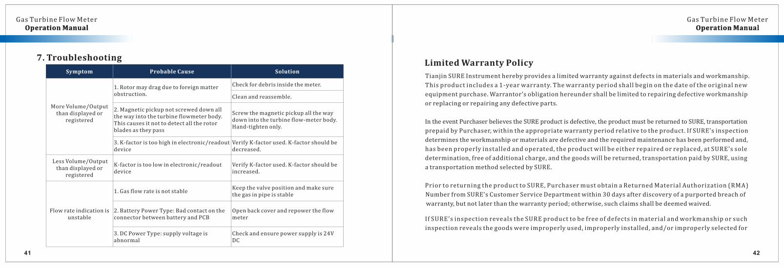
Symptom ProbableCause Solution
MoreVolume/Outputthandisplayedor
registered
1.Rotormaydragduetoforeignmatterobstruction.
Checkfordebrisinsidethemeter.
Cleanandreassemble.
2.Magneticpickupnotscreweddownallthewayintotheturbineflowmeterbody.Thiscausesitnottodetectalltherotorbladesastheypass
Screwthemagneticpickupallthewaydownintotheturbineflow-meterbody.Hand-tightenonly.
3.K-factoristoohighinelectronic/readoutdevice
VerifyK-factorused.K-factorshouldbedecreased.
LessVolume/Outputthandisplayedor
registered
K-factoristoolowinelectronic/readoutdevice
VerifyK-factorused.K-factorshouldbeincreased.
Flowrateindicationisunstable
1.GasflowrateisnotstableKeepthevalvepositionandmakesurethegasinpipeisstable
2.BatteryPowerType:BadcontactontheconnectorbetweenbatteryandPCB
Openbackcoverandrepowertheflowmeter
3.DCPowerType:supplyvoltageisabnormal
Checkandensurepowersupplyis24VDC
7. TroubleshootingLimitedWarrantyPolicy
TianjinSUREInstrumentherebyprovidesalimitedwarrantyagainstdefectsinmaterialsandworkmanship.
Thisproductincludesa1-yearwarranty.Thewarrantyperiodshallbeginonthedateoftheoriginalnew
equipmentpurchase.Warrantor’sobligationhereundershallbelimitedtorepairingdefectiveworkmanship
orreplacingorrepairinganydefectiveparts.
IntheeventPurchaserbelievestheSUREproductisdefective,theproductmustbereturnedtoSURE,transportation
prepaidbyPurchaser,withintheappropriatewarrantyperiodrelativetotheproduct.IfSURE’sinspection
determinestheworkmanshipormaterialsaredefectiveandtherequiredmaintenancehasbeenperformedand,
hasbeenproperlyinstalledandoperated,theproductwillbeeitherrepairedorreplaced,atSURE’ssole
determination,freeofadditionalcharge,andthegoodswillbereturned,transportationpaidbySURE,using
atransportationmethodselectedbySURE.
PriortoreturningtheproducttoSURE,PurchasermustobtainaReturnedMaterialAuthorization(RMA)
NumberfromSURE’sCustomerServiceDepartmentwithin30daysafterdiscoveryofapurportedbreachof
warranty,butnotlaterthanthewarrantyperiod;otherwise,suchclaimsshallbedeemedwaived.
IfSURE’sinspectionrevealstheSUREproducttobefreeofdefectsinmaterialandworkmanshiporsuch
inspectionrevealsthegoodswereimproperlyused,improperlyinstalled,and/orimproperlyselectedfor
OperationManual OperationManual
4443
GasTurbineFlowMeterOperationManual OperationManual
GasTurbineFlowMeter
serviceintended,SUREwillnotifythepurchaserinwritingandwilldeliverthegoodsbacktoPurchaserupon
ReceiptofPurchaser'swritteninstructionsandagreementtopaythecostoftransportation.IfPurchaserdoes
Notrespondwithinthirty(30)daysafternoticefromSURE,thegoodswillbedisposedofinSURE’sdiscretion.
SUREdoesnotwarranttheproducttomeettherequirementsofanysafetycodeorotherjurisdiction,and
Purchaserassumesallriskandliabilitywhatsoeverresultingfromtheusethereof,whetherusedsinglelyorin
combinationwithothermachinesorapparatus.
ThiswarrantyshallnotapplytoanySUREproductorpartsthereof,whichhavebeenrepairedoutsideSURE’s
factoryoralteredinanyway,orhavebeensubjecttomisuse,negligence,oraccident,orhavenotbeenoperated
inaccordancewithSURE’sprintedinstructionsorhavebeenoperatedunderconditionsmoreseverethan,or
otherwiseexceeding,thosesetinthespecifications.
FORNON-WARRANTYREPAIRSORCALIBRATIONS,consultusforcurrentrepair/calibrationcharges.Have
thefollowinginformationavailableBEFOREcontactingus:
1. P.O.numbertocovertheCOSToftherepair/calibration,
2. Modelandserialnumberoftheproduct
3. Repairinstructionsand/orspecificproblemsrelativetotheproduct.
Thispageisblank
RESERVED