Embed Size (px)
Citation preview
Tunnels & Tunnelling
Experience Record
TEC v.o.f. Tunnel Engineering Consultants P.O. Box 28013 3828 ZG Amersfoort The Netherlands Office: Laan 1914 no 35 3818 EX Amersfoort The Netherlands Telephone: +31(0)88 348 2540 E-mail: [email protected] Internet: www.TEC-tunnel.com
3
TABLE OF CONTENT
INTRODUCTION 4
TEC PROFILE 5
SERVICES 7
CUT & COVER TUNNELS 8 Gibraltar Airport tunnel 9 Freight traffic tunnel at Amsterdam Schiphol Airport, The Netherlands 10 HOV-tunnel Zuid Tangent, The Netherlands 11 Shindagha tunnel, Dubai, United Arab Emirates 12 Markt-Maas tunnel, Maastricht, The Netherlands 13 Stations in North/South Metro line, The Netherlands 14 Tunnel Giessen, the Netherlands 22 Gongbei tunnel, Zhuhai, China 23 Nijverdal, The Netherlands 24 Station Boxes Metro Red Line Tel Aviv – Israel 25 Mexico City New International Airport 28 Metro Arenastaden, Stockholm, Sweden 30
4
INTRODUCTION
Tunnel Engineering Consultants (TEC) is a Joint Venture of Royal
HaskoningDHV (RHDHV) and Witteveen+Bos (W+B). TEC combines knowledge,
expertise and experience of the mother companies (8000 professionals) within
the field of large underground projects.
TEC guarantees continuity and specialized knowledge of tunnel design and
construction to solve complicated underground mobility challenges through an
integral, innovative and sustainable project approach.
In addition, TEC is able to draw on the considerable expertise of two Dutch
engineering consultancy firms and covering the entire range of civil, structural
and architectural engineering required for small and large building projects,
environmental impact assessment, legal aspects and project management.
This TEC experience record intends to give an impression of the capabilities of
Tunnel Engineering Consultants in the field of tunnel related design and tunnel
construction related consultancy. It will provide an overview of services that TEC
can offer within the preparation and realization of tunnel project.
This document provides a selection of appealing projects in which TEC was and
is involved including the position TEC had in the project.
5
TEC PROFILE
Tunnel Engineering Consultants v.o.f. (TEC) is specialised in consultancy works
for underground infrastructure and tunnel projects. TEC is established in 1988 as
a Joint Venture between two major engineering consultancy firms:
Royal HaskoningDHV
Witteveen+Bos Consulting Engineers b.v.
Profile TEC’s key expertise is tunnels; in-situ land tunnels, bored as well as Cut&Cover
and immersed tube tunnels. The Scope of work comprises tunnel design with
construction supervision including the mechanical and electrical tunnel
installations. Together with the Dutch Ministry of Transport and Public Works –
Tunnel engineering Department (Rijkswaterstaat), TEC developed advanced
knowledge in tunnel engineering.
The participating firms employ more than 8000 engineers and specialists and
have a total annual turnover of about 748 million EURO (2016). They have
subsidiaries and branch offices in countries worldwide.
Royal HaskoningDHV
www.royalhaskoningdhv.com
Royal HaskoningDHV is a leading independent, international project
management and engineering consultancy service provider. Specialising in
planning and transport, infrastructure, water, maritime, aviation, industry, energy,
mining and buildings, each year we contribute to the del ivery of some 30,000
projects around the world on behalf of our public and private sector clients.
Our 6,500 staff adds value to our client’s projects by providing a local
professional service in more than 35 countries, via our fully integrated
international office network. As leaders in sustainability and innovation, we are
deeply committed to continuous improvement, business integrity and sustainable
development, and work with our clients, stakeholders and communities to
enhance society together.
Prior to the merger on 1 July 2012, Royal Haskoning and DHV have successfully
delivered millions of world class projects during the past two centuries. With
roots established in The Netherlands, the UK and South Africa, our combined
experience and longevity spans more than 225 years. Now, as one company, we
have the power to make a bigger difference in the world as we rise to the
challenges of our 21st century planet, towards a better, brighter future.
Today Royal HaskoningDHV ranks in the top 10 of global, independently owned,
non-listed companies and top 40 overall. This makes us the first choice
consultancy provider for involvement in major world themes, such as ‘pit -to-port’,
food and water scarcity, the development of mega-cities, and sustainable
infrastructure and energy resources & supply, such as wave and hydro power.
We are also well positioned to contribute to the latest business models, such as
Public-Private Partnership.

6
Witteveen+Bos Consulting Engineers b.v.
www.witteveenbos.com
Witteveen+Bos is a private limited company whose shares are owned entirely by
its employees, who are either participants, partners or senior partners. This
unique ownership structure ensures above-average commitment, good financial
performance and a high profile. It is a structure that appeals to our clients,
because it gives them confidence in our commitment. Our net result is paid out
entirely as a dividend to our shareholders, so they share in large measure in the
company’s result.
The Witteveen+Bos organisation is built around the cells concept that we have
shaped in the form of PMCs (product market combinations). Organisationally, the
PMCs are clustered into five sectors. The five sectors are: Ports and hydraulic
engineering, Spatial development and the environment, Urban development and
traffic, Water, and Infrastructure and Construction,
Next to the offices in The Netherlands, Witteveen+Bos also has offices in
Belgium, Kazakhstan, Indonesia, Russia and Latvia.
Witteveen+Bos is committed to being a first-rate consultancy and engineering
firm. Performing at the very highest level is a precondition for achieving this
goal. We think striving for the top is a healthy ambition. A national and
international orientation towards products, markets and the labour market is
essential to operating being the best in our field of work.
Internationally, Witteveen+Bos has achieved a good position in the following
areas:
preparation, transport and distribution of drinking water
effluent treatment
water management
environmental technology and policy
ports, dredging, coastal water engineering, river water engineering
tunnels
7
SERVICES
TEC provides a full range of consultancy services from feasibility studies,
design, tender documents, tender evaluation, design reviews, value engineering,
cost analysis, detailed design, and construction supervision to project
management for underground engineering, related electrical and mechanical
works and traffic engineering. In addit ion, we are able to draw on the
considerable expertise of two Dutch engineering consultancy firms covering the
entire range of civil, structural and architectural engineering required for small
and large building projects, environmental impact assessment, legal aspects and
project management.
Moreover, TEC has at their disposal specific expertise of the Dutch Ministry of
Transport and Public works – Tunnel Engineering Department (Rijkswaterstaat),
a governmental organisation involved as designer and owner / operator in about
26 road and railway tunnels and their installations in the Netherlands.
Expertise Civil
immersed tunnels
shield tunnels in soft soil
cut & cover tunnels
pneumatic caissons
Electro mechanical installations
ventilation
pumps
lighting
power supply
traffic control
operation
Safety aspects
Safety analysis
Operational procedures
QRA and Scenario Analysis
Risk assessment & Value
Engineering
8
CUT & COVER TUNNELS
General
TEC, a permanent joint venture between Royal HaskoningDHV and
Witteveen+Bos has been involved in the following cut & cover tunnel projects:
Gibraltar Airport tunnel
Freight traffic tunnel at Amsterdam Schiphol Airport, The Netherlands
HOV-tunnel Zuid Tangent, The Netherlands
Shindagha tunnel, Dubai, United Arab Emirates
Markt-Maas tunnel, Maastricht, The Netherlands
Stations in North/South Metro line, The Netherlands
Metro station Central Station
Metro station Rokin
Metro station Vijzelgracht
Metro station Ceintuurbaan
Metro Station RAI/Europaplein
Tunnel Giessen, the Netherlands
Gongbei tunnel, Zhuhai, China
Nijverdal, the Netherlands
Station Boxes Metro Red Line Tel Aviv – Israel
Mexico City New International Airport
Metro Arenastaden, Stockholm, Sweden

9
Gibraltar Airport tunnel
Project
The main tunnel will be a concrete structure comprising three bores (two road
and one subway) separated by two walls. The subway comprises a lane for
cyclists and pedestrians and one for plant corridor.
The tunnel is classified as Category B in accordance with BD78/99.
The length between portals is approximately 350 m on a 265 m horizontal radius.
TEC’s scope of work
TEC provided the tender design for the Contractor, Volker Stevin Construction
Europe.

10
Freight traffic tunnel at Amsterdam Schiphol Airport, The Netherlands
Project
As Schiphol continuous to grow, so does the need for proper freight handling.
Schiphol Group initiated a new area for handling freight operations, and asked
the Dutch Tunnel Engineering Consultants (TEC), in which Royal Haskoning
participates, to provide a project study and design for a new freight handling
area located just south-east of the runway 06-24.
To connect the new freight area with the centre of Schiphol, a tunnel was built.
The tunnel has a width of 13 m and a total length of 850 m, with an enclosed
tunnel length of 550 m.
The tunnel crosses the runway and two taxi-ways. At the northern entrance of
the tunnel, a connection with an existing tunnel, running perpendicular, had to be
constructed. In order to reduce the time in which the runway 0624 is not in use,
in relation to construction costs, a number of construction methods were
evaluated. Amongst these different methods, are the cut & cover method, an
immersed tunnel, a bored tunnel, and the “wall roof” method.
The method that appeared to be the most suitable was the “wall roof” method.
This is a method in which the walls and the roof of the tunnel are constructed
first in order to restore the runway as soon as possible; after this, the soil in the
tunnel is excavated and the base slab of the tunnel is constructed.
The walls are made up of steel tubes with sheet-piles in between (combi-wall).
The roof is made with pre-stressed prefabricated beams and the base slab is
made up of reinforced in-situ concrete.
TEC’s scope of work
TEC provided the feasibility study, cost estimates, design, contract specifications for a
traditional and “design and build” contract. In addition, all services that were provided included
electrical and mechanical installations.

11
HOV-tunnel Zuid Tangent, The Netherlands
Project
The tunnel is part of the cored part of the High-quality Public Transport Line
Zuid-Tangent between Haarlem and Schiphol-east.
The tunnel has one tube comprising two lanes for busses or , in the future, two
fast trams.
The tunnel crosses the new A5 motorway, the existing A4 and a taxiway of
Schiphol Airport.
The approaches consist of open through concrete sections. The first 50% of the
sections are build in the time the Zwanenburgbaan (a runway of Schiphol) was
reconstructed and when the highway A4 was deflected for the building of a
second train tunnel between Hoofddorp and Schiphol.
TEC’s scope of work
TEC provided the following:
Preliminary design and detailed design of the concrete works
Tender documents and assistance to the client with the selection of the
contractor
Construction supervision
12
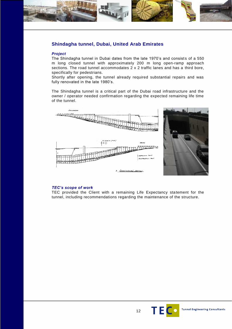
Shindagha tunnel, Dubai, United Arab Emirates
Project
The Shindagha tunnel in Dubai dates from the late 1970’s and consists of a 550
m long closed tunnel with approximately 200 m long open-ramp approach
sections. The road tunnel accommodates 2 x 2 traffic lanes and has a third bore,
specifically for pedestrians.
Shortly after opening, the tunnel already required substantial repairs and was
fully renovated in the late 1980’s.
The Shindagha tunnel is a critical part of the Dubai road infrastructure and the
owner / operator needed confirmation regarding the expected remaining life time
of the tunnel.
TEC’s scope of work
TEC provided the Client with a remaining Life Expectancy sta tement for the
tunnel, including recommendations regarding the maintenance of the structure.

13
Markt-Maas tunnel, Maastricht, The Netherlands
Project
The project involved the inner-urban redevelopment of the area between the
market and the western bank of the river the Maas in the city of Maastricht. The
development consists of a four-storied underground car parking station, with a
shopping centre and governmental offices above it.
Furthermore, a 400 m long under the Maas Boulevard is also part of the project.
From this tunnel, underground facilities will be available for easy access to the
shopping centre and the government offices. In addition, the tunnels will
accommodate separate entry and exit lanes in and out of the car park. As a
result, the middle section of the tunnel is constructed in two levels.
The Wilhelmina Bridge, that crosses the Maas at this location, needs to be
modified and a new abutment on the western bank of the Maas, at the same
level as the tunnel roof, is designed and constructed.
TEC’s scope of work
For this project, TEC partner Royal Haskoning was responsible for all the
designs and supervision during the realization of the tunnel and the adjustments
to the bridge. This applies for the civil engineering as well as the tunnel technical
installations designs; power supply, lighting, drainage, ventilation, fire safety,
traffic signalling, communications and operations. Special aspects of the tunnel
included its complex geometry, the unique geotechnical soil conditions which
consisted of limestone and gravel, the position along the Maas, and the
ventilation towers.
14
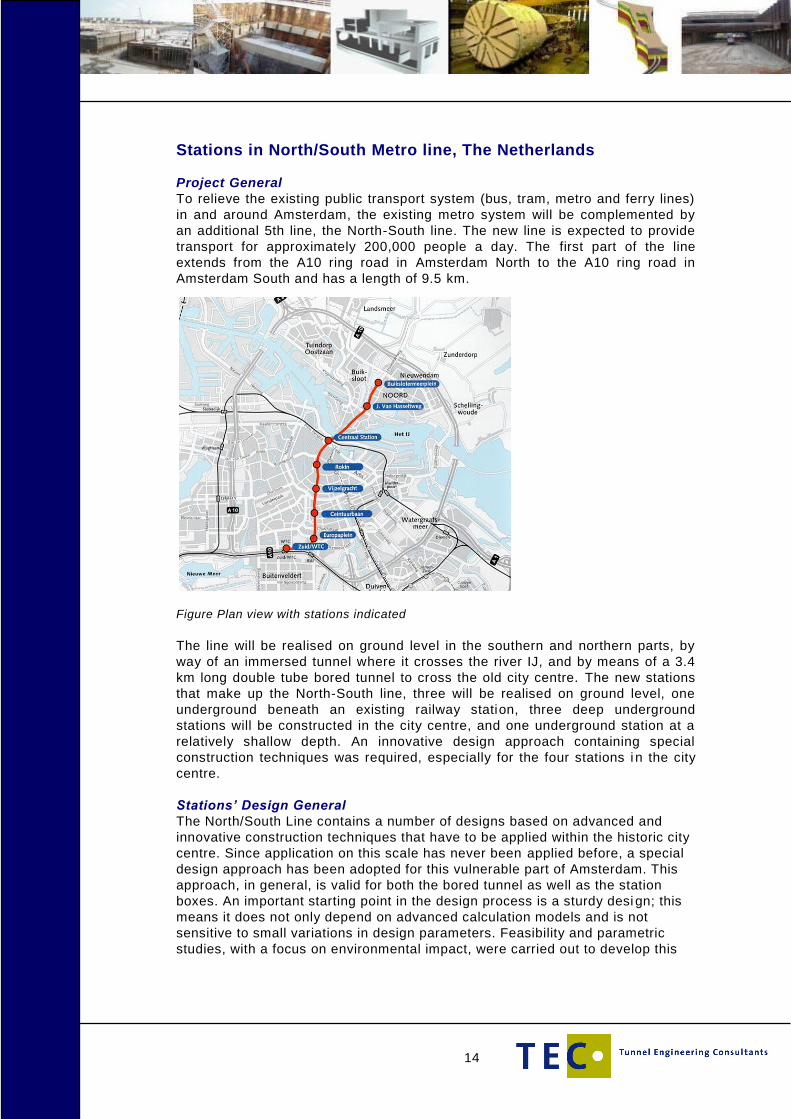
Stations in North/South Metro line, The Netherlands
Project General
To relieve the existing public transport system (bus, tram, metro and ferry lines)
in and around Amsterdam, the existing metro system will be complemented by
an additional 5th line, the North-South line. The new line is expected to provide
transport for approximately 200,000 people a day. The first part of the line
extends from the A10 ring road in Amsterdam North to the A10 ring road in
Amsterdam South and has a length of 9.5 km.
Figure Plan view with stations indicated
The line will be realised on ground level in the southern and northern parts, by
way of an immersed tunnel where it crosses the river IJ, and by means of a 3.4
km long double tube bored tunnel to cross the old city centre. The new stations
that make up the North-South line, three will be realised on ground level, one
underground beneath an existing railway station, three deep underground
stations will be constructed in the city centre, and one underground station at a
relatively shallow depth. An innovative design approach containing special
construction techniques was required, especially for the four stations i n the city
centre.
Stations’ Design General
The North/South Line contains a number of designs based on advanced and
innovative construction techniques that have to be applied within the historic city
centre. Since application on this scale has never been applied before, a special
design approach has been adopted for this vulnerable part of Amsterdam. This
approach, in general, is valid for both the bored tunnel as well as the station
boxes. An important starting point in the design process is a sturdy desi gn; this
means it does not only depend on advanced calculation models and is not
sensitive to small variations in design parameters. Feasibility and parametric
studies, with a focus on environmental impact, were carried out to develop this

15
sturdy design. In addition, all aspects of the design had to be completed and
confirmed, which included the following:
Extensive soil investigations including special tests that can accommodate
data for the advanced calculation models that have been applied.
Extensive desk studies to investigate building response (brick buildings on
wooden pile foundations) to settlement induced deformations due to
construction investigating the present state of the buildings alongside the
alignment followed by a building classification, and in a number of cases
suggestions for foundation reinforcement.
Development of FE models considering the construction process for
predictions and back analyses.
A monitoring program to measure deformations of the buildings, subsoil and
North/South Line structures (e.g. building pit walls).
Development of back up measurements to implement in the design if
anticipation on monitoring data is required.
Figure: Typical historic Amsterdam building and FE Model
There was a lack of knowledge when applying the innovative design aspects;
in these cases international recognised experts or institutes were consulted
and the designs were reviewed. Furthermore, full scale tests were carried out
to investigate the impact of construction techniques as a means of verifying
and validating the calculation models that had been developed. The next set
of tests that have been carried out are as follows.
The test pile project to investigate the impact of tunnel boring activities to
pile foundations.
The environmental impact of diaphragm wall installation.
The effect of grouting techniques (jet grouting, permeation grouting,
compensation grouting).
Freezing test.
Test to investigate lining design.
Tail injection test for the bored tunnel with a focus on limiting the
environmental impact.
This approach, based upon the observational method, was applied for
several designs within this project, and fine tuned to a tailor made concept to
meet the specific boundary conditions for each location.
16
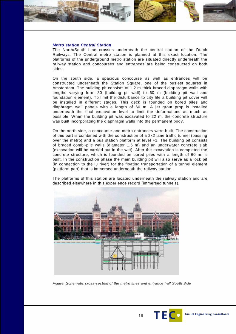
Metro station Central Station
The North/South Line crosses underneath the central station of the Dutch
Railways. The Central metro station is planned at this exact location. The
platforms of the underground metro station are situated directly underneath the
railway station and concourses and entrances are being constructed on both
sides.
On the south side, a spacious concourse as well as entrances will be
constructed underneath the Station Square, one of the busiest squares in
Amsterdam. The building pit consists of 1.2 m thick braced diaphragm walls with
lengths varying form 30 (building pit wall) to 60 m (building pit wall and
foundation element). To limit the disturbance to city life a building pit cover will
be installed in different stages. This deck is founded on bored piles and
diaphragm wall panels with a length of 60 m. A jet grout prop is installed
underneath the final excavation level to limit the deformations as much as
possible. When the building pit was excavated to 22 m, the concrete structure
was built incorporating the diaphragm walls into the permanent body.
On the north side, a concourse and metro entrances were built. The construction
of this part is combined with the construction of a 2x2 lane traffic tunnel (passing
over the metro) and a bus station platform at level +1. The building pit consists
of braced combi-pile walls (diameter 1.6 m) and an underwater concrete slab
(excavation will be carried out in the wet). After the excavation is completed the
concrete structure, which is founded on bored piles with a length of 60 m, is
built. In the construction phase the main building pit will also serve as a lock pit
(in connection to the IJ river) for the floating transportation of a tunnel element
(platform part) that is immersed underneath the railway station.
The platforms of this station are located underneath the railway station and are
described elsewhere in this experience record (immersed tunnels).
Figure: Schematic cross-section of the metro lines and entrance hall South Side
17
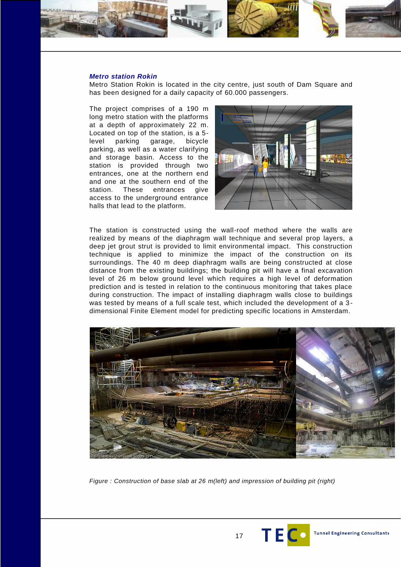
Metro station Rokin
Metro Station Rokin is located in the city centre, just south of Dam Square and
has been designed for a daily capacity of 60.000 passengers.
The project comprises of a 190 m
long metro station with the platforms
at a depth of approximately 22 m.
Located on top of the station, is a 5-
level parking garage, bicycle
parking, as well as a water clarifying
and storage basin. Access to the
station is provided through two
entrances, one at the northern end
and one at the southern end of the
station. These entrances give
access to the underground entrance
halls that lead to the platform.
The station is constructed using the wall-roof method where the walls are
realized by means of the diaphragm wall technique and several prop layers, a
deep jet grout strut is provided to limit environmental impact. This construction
technique is applied to minimize the impact of the construction on its
surroundings. The 40 m deep diaphragm walls are being constructed at close
distance from the existing buildings; the building pit will have a final excavation
level of 26 m below ground level which requires a high level of deformation
prediction and is tested in relation to the continuous monitoring that takes place
during construction. The impact of installing diaphragm walls close to buildings
was tested by means of a full scale test, which included the development of a 3 -
dimensional Finite Element model for predicting specific locations in Amsterdam.
Figure : Construction of base slab at 26 m(left) and impression of building pit (right)

18
Metro station Vijzelgracht
Metro Station Vijzelgracht is located in the city centre and has a total length of
approx. 260 m; the platform will be at a depth of about 26 m and some 30,000
passengers are expected to use this station each day. The station will have three
entrances.
In the space above the underground station, a so-called detention-and-settling
tank will be created to serve as an overflow area for excess rainwater drainage.
There are plans for underground parking facilities for both cars and bicycles in
the future.
Figure Rendering longitudinal section of Vijzelgracht station
The station is constructed applying the same methods as used for Rokin Station.
Since the excavation level was approx. 32 m, the stability of the base of the deep
part of the excavation had to be secured using compressed air conditions.
Figure: Impression of excavation deep part of the building pit under compressed air
conditions.

19
Metro station Ceintuurbaan
Ceintuurbaan is the southernmost metro station in the city centre. It is located in
the very narrow Ferdinand Bolstraat, for which reason the station has been
accommodated with stacked platforms. This allowed for the narrowest possible
station lay-out. The consequence however was a very deep station with
platforms at 16.5 m and 26.5 m respectively and an excavation level of over 32
m. This station has two entrances and is supposed to allow for some 35,000
passengers per day.
Figure:
Rendering of
station
The station is constructed applying the same methods used for Rokin and
Vijzelgracht Station. As for Vijzelgracht Station the deep part of the excavation
had to be carried out under compressed air conditions.
.
Figure: Diaphragm wall construction Figure: Station under construction

20
Metro Station RAI/Europaplein
Metro Station RAI/Europaplein is one of the 8 stations of the North/South metro
line in Amsterdam and located at the southern side of the line in front of the
Amsterdam exhibition centre RAI. The station has been designed for a daily
capacity of 27,500 passengers.
The project comprises of a 200 m metro station as well as two adjoining tunnels,
one north of the station measuring 235 m, and one south of it, measuring 270 m.
The tunnel sections and station are below ground level and were realised using
the cut-and-cover construction method.
The construction pits consisted of steel sheet-walls with girders and struts, and
an underwater concrete floor with tension piles. A reception shaft was made for
the 2 tunnel boring machines which were used to bore the tunnel sections under
the city centre, as well as for the emergency exits. The reception shaft is located
at the northern end of the project site, at this location the construction pit will
reach a depth of approximately 20 m, and the northern tunnel will gradually rise
to a depth of 9 m and the southern tunnel will rise to a depth of 7 m.
Access to the station is provided by two entrances which lead to underground
distribution areas and is equipped with extensive safety systems in case of an
emergency.
Figure: Tunnel under
construction
Figure: Main civil works for Station completed
21
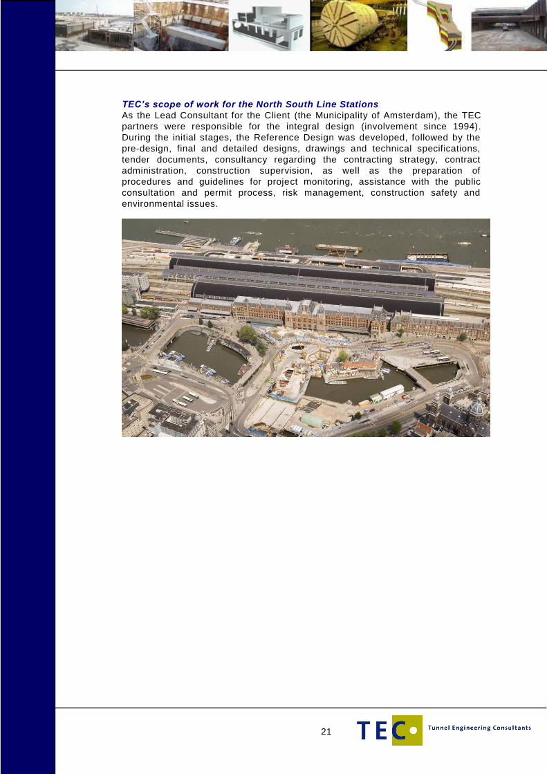
TEC’s scope of work for the North South Line Stations
As the Lead Consultant for the Client (the Municipality of Amsterdam), the TEC
partners were responsible for the integral design (involvement since 1994).
During the initial stages, the Reference Design was developed, followed by the
pre-design, final and detailed designs, drawings and technical specifications,
tender documents, consultancy regarding the contracting strategy, contract
administration, construction supervision, as well as the preparation of
procedures and guidelines for project monitoring, assistance with the public
consultation and permit process, risk management, construction safety and
environmental issues.

22
Tunnel Giessen, the Netherlands
Project
A railway tunnel running under the Giessen, is one of the structures designed as
part of the “Betuweroute.” The Betuweroute is the newly dedicated freight railway
line, measuring a length of 160 km, stretching across the Netherlands and linking
Rotterdam’s busy port to the existing German rail network.
In this particular location in Giessenlanden, the Betuweroute does not follow the
path of the existing infrastructure within the area, which consists of highway A15
and the railway Dordrecht-Geldermalsen, but instead its location is more to the
North to spare the buildings located in the area. To cross the river Giessen, a
tunnel with two separate tubes was built in a construction pit. In an earlier
planning stage, a preliminary design was made for a bridge to cross the river, but
due to environmental aspects, a tunnel was chosen instead.
The tunnel consists of a covered part with a length of 500 m which is located
directly under the Giessen. There is an open access ramp located on both sides
of the tunnel. The access ramp on the west side has a length of 490 m and the
east side ramp has a length of 400 m.
During construction, the water drainage as well as the shipping on the river de
Giessen could not be interrupted, therefore the construction was carried out in
two stages. In the first stage, the west side of the tunnel was built, but only half
way across the river so that water drainage and shipping was still possible. After
completion of the west side of the tunnel, the construction pit was moved to the
other side, enabling the construction of the east side to be made.
Figure: Tunnel under the Giessen under construction
TEC’s scope of work
TEC has been involved through its partner Royal Haskoning who carried out the
feasibility study for this project, as well as the preliminary design, final design,
and the write-up of tender documents

23
Gongbei tunnel, Zhuhai, China
Project
The Zhuhai Link is part of the overall Hong-Kong - Macau – Zhuhai Link and has
a length of some 14 km and consists of a bridge that runs from the Zhuhai-
Macau BCF island towards the main land where it converts into a tunnel
underneath the Gongbei Border Crossing Facility. It surfaces further to the west
to cross the Qian-shan-River and Nan-Wan Road in the form of bridges, and
then travels southward as a tunnel through the Nan-Ping Mountain. The final
stretch that runs in western direction consists of viaducts with connections to the
Heng-Qin North interchange and Hong-Wan interchange. The key technical
challenge is the tunnel underneath the China – Macau border crossing facilities.
TEC’s scope of work
Risk Assessment and development of risk control measures for design scheme
and construction organisation of 3 alignments with a total of 6 configurations
comprising Open-excavation top-down and Sub-surface excavation methods for
the Gongbei BCF Tunnel section in preliminary design stage that included
following content:
Risk assessment and control measures for technical schemes for main works
of the tunnel and for construction organization schemes for main works of the
tunnel.
Risk assessment and control measures for the design schemes of traffic
engineering and auxiliary facilities (including rescue system) of the tunnel.
The effect of tunnel technical schemes on operational management.
The Risk Assessment has been carried out in compliance with the China ”Risk
assessment guidance for highway tunnel safety” (Version for trial) complemented
by International accepted risk assessment methodology.
24
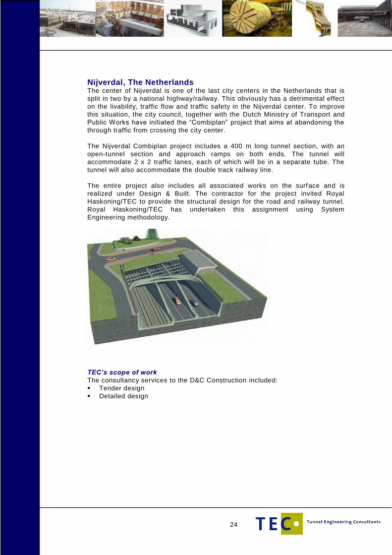
Nijverdal, The Netherlands The center of Nijverdal is one of the last city centers in the Netherlands that is
split in two by a national highway/railway. This obviously has a detrimental effect
on the livability, traffic flow and traffic safety in the Nijverdal center. To improve
this situation, the city council, together with the Dutch Ministry of Transport and
Public Works have initiated the “Combiplan” project that aims at abandoning the
through traffic from crossing the city center.
The Nijverdal Combiplan project includes a 400 m long tunnel section, with an
open-tunnel section and approach ramps on both ends. The tunnel will
accommodate 2 x 2 traffic lanes, each of which will be in a separate tube. The
tunnel will also accommodate the double track railway line.
The entire project also includes all associated works on the surface and is
realized under Design & Built. The contractor for the project invited Royal
Haskoning/TEC to provide the structural design for the road and railway tunnel.
Royal Haskoning/TEC has undertaken this assignment using System
Engineering methodology.
TEC’s scope of work
The consultancy services to the D&C Construction included:
Tender design
Detailed design
25
Station Boxes Metro Red Line Tel Aviv – Israel
Project
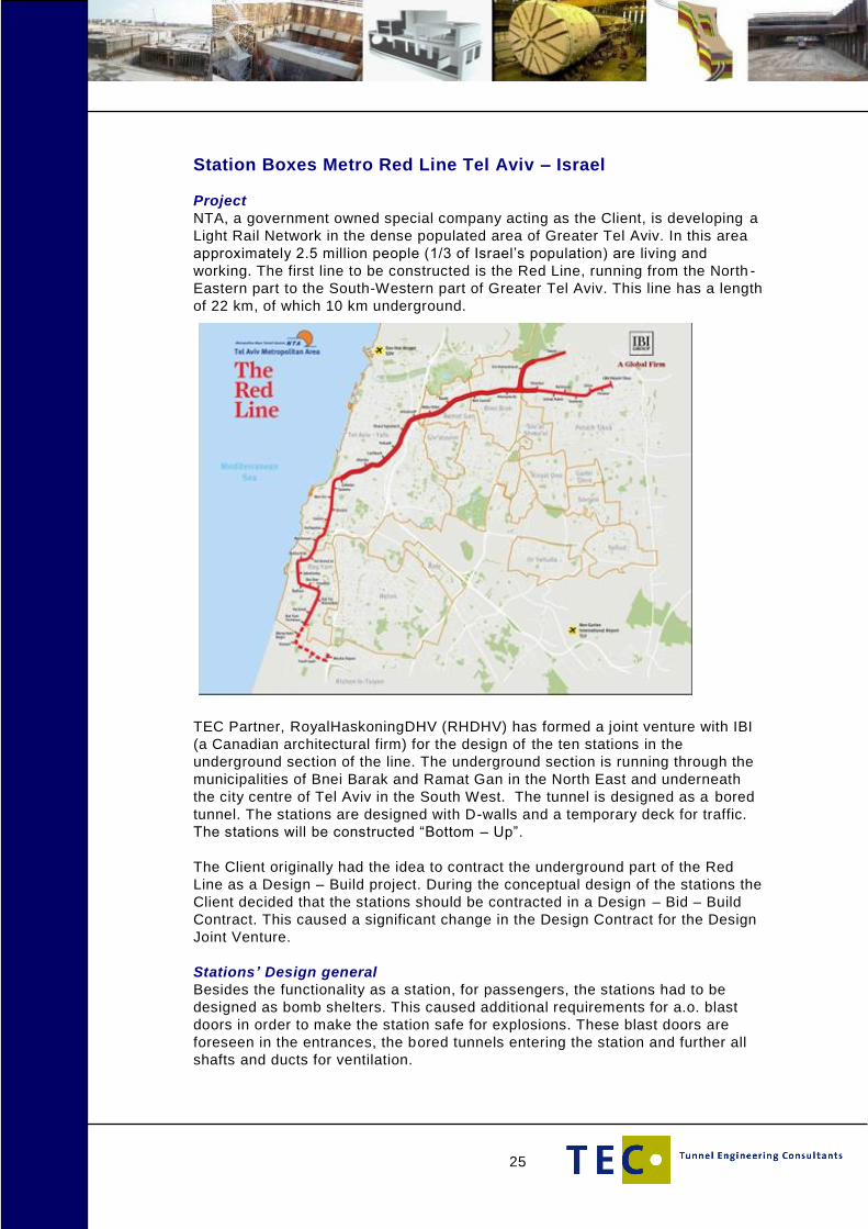
NTA, a government owned special company acting as the Client, is developing a
Light Rail Network in the dense populated area of Greater Tel Aviv. In this area
approximately 2.5 million people (1/3 of Israel’s population) are living and
working. The first line to be constructed is the Red Line, running from the North -
Eastern part to the South-Western part of Greater Tel Aviv. This line has a length
of 22 km, of which 10 km underground.
TEC Partner, RoyalHaskoningDHV (RHDHV) has formed a joint venture with IBI
(a Canadian architectural firm) for the design of the ten stations in the
underground section of the line. The underground section is running through the
municipalities of Bnei Barak and Ramat Gan in the North East and underneath
the city centre of Tel Aviv in the South West. The tunnel is designed as a bored
tunnel. The stations are designed with D-walls and a temporary deck for traffic.
The stations will be constructed “Bottom – Up”.
The Client originally had the idea to contract the underground part of the Red
Line as a Design – Build project. During the conceptual design of the stations the
Client decided that the stations should be contracted in a Design – Bid – Build
Contract. This caused a significant change in the Design Contract for the Design
Joint Venture.
Stations’ Design general
Besides the functionality as a station, for passengers, the stations had to be
designed as bomb shelters. This caused additional requirements for a.o. blast
doors in order to make the station safe for explosions. These blast doors are
foreseen in the entrances, the bored tunnels entering the station and further all
shafts and ducts for ventilation.
26
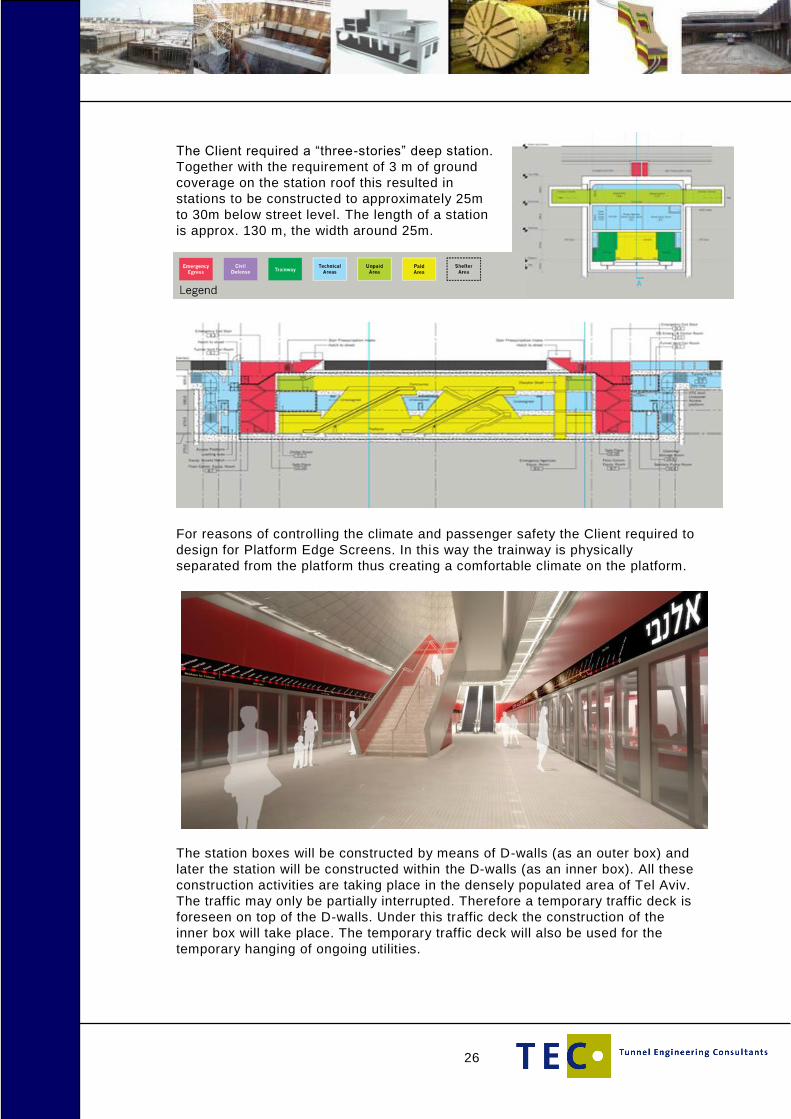
The Client required a “three-stories” deep station.
Together with the requirement of 3 m of ground
coverage on the station roof this resulted in
stations to be constructed to approximately 25m
to 30m below street level. The length of a station
is approx. 130 m, the width around 25m.
For reasons of controlling the climate and passenger safety the Client required to
design for Platform Edge Screens. In this way the trainway is physically
separated from the platform thus creating a comfortable climate on the platform.
The station boxes will be constructed by means of D-walls (as an outer box) and
later the station will be constructed within the D-walls (as an inner box). All these
construction activities are taking place in the densely populated area of Tel Aviv.
The traffic may only be partially interrupted. Therefore a temporary traffic deck is
foreseen on top of the D-walls. Under this traffic deck the construction of the
inner box will take place. The temporary traffic deck will also be used for the
temporary hanging of ongoing utilities.

27
The D-walls together with the excavation will cause settlements of the
surrounding area and buildings. After having defined an additional Soil
Investigation programme a detailed report on the Zone of Influence has been
produced before obtaining the building permits.
Complicating aspects/requirements in the design were:
1. quantity of water to be extracted from the bottom
due to the limited quantity of water which might be pumped away the
excavation had to be designed as a “wet-excavation”. This required the
application of underwater concrete
2. tie-backs or horizontal ground anchors were not allowed
due to the fact that the adjacent buildings are private owned the Client
did not want to take the risks for legal delays with arranging the right
for installation of the ground anchors. Therefore the design had to
apply struts and girder beams
3. the ongoing traffic
due to the limited space for the various construction stages
sometimes four or five stages had to be applied for the
construction of the outer box. This had to be combined with the
same number of traffic diversions and relocation of utilities. Thus
resulting in complicated permitting arrangements with all
stakeholders.
The design joint venture is responsible for the design. However the majority
(80%) of the structural and foundation design was executed by local sub -
consultants (as is the case for the M&E as well). The joint venture kept the tasks
of managing the process, reviewing the designs, advising on strategic level for
3D-geotechnical calculations, geo-hydrology, special techniques like underwater
concrete and RAMS-aspects.
TEC’s (RHDHV) scope of work
Within the joint venture (IBI/RHDHV) RHDHV is the lead consultant (and ultimate
responsible) for the integrated design of the five underground stations in the
municipality of Tel Aviv. The design comprises the conceptual design, the
preliminary design, the final design, the tender design and the detailed design
inclusive of the construction documents. Next to these design works RHDHV will
also be involved in the supervision of the Works. Since the services covers the
integrated design the following disciplines were supplied by RHDHV: structural,
geotechnical and M&E design, as well as the management thereof and the
management over the disciplines architecture, traffic diversions, utility relocation
and road restoration. Also the permitting process with the m unicipality formed a
part of the scope.
Since approximately 80% of the services were executed by local sub consultants
a major task was in managing the various subconsultants. Each station had its ’
own “set” of subconsultants, therefore RHDHV had to manage multiple contracts
with these sub consultants. A dedicated team (of both Dutch and Israeli people)
worked close together. As a result of bringing together various subconsultants
with a same technical discipline advantages in the design process were achie ved
like a uniform design of e.g. the blast doors, the grounding system or the water
proofing concept.
28
Mexico City New International Airport
Project
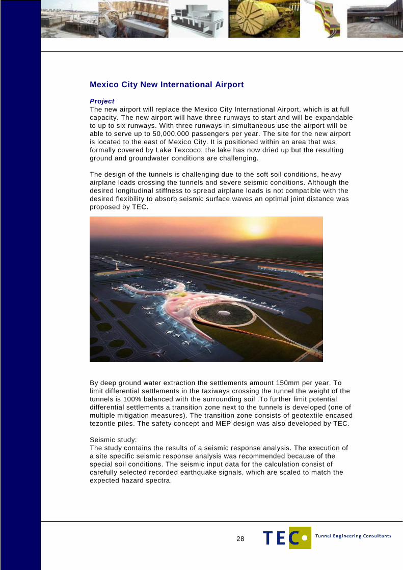
The new airport will replace the Mexico City International Airport, which is at full
capacity. The new airport will have three runways to start and will be expandable
to up to six runways. With three runways in simultaneous use the airport will be
able to serve up to 50,000,000 passengers per year. The site for the new airport
is located to the east of Mexico City. It is positioned within an area that was
formally covered by Lake Texcoco; the lake has now dried up but the resulting
ground and groundwater conditions are challenging.
The design of the tunnels is challenging due to the soft soil conditions, he avy
airplane loads crossing the tunnels and severe seismic conditions. Although the
desired longitudinal stiffness to spread airplane loads is not compatible with the
desired flexibility to absorb seismic surface waves an optimal joint distance was
proposed by TEC.
By deep ground water extraction the settlements amount 150mm per year. To
limit differential settlements in the taxiways crossing the tunnel the weight of the
tunnels is 100% balanced with the surrounding soil .To further limit potential
differential settlements a transition zone next to the tunnels is developed (one of
multiple mitigation measures). The transition zone consists of geotextile encased
tezontle piles. The safety concept and MEP design was also developed by TEC.
Seismic study:
The study contains the results of a seismic response analysis. The execution of
a site specific seismic response analysis was recommended because of the
special soil conditions. The seismic input data for the calculation consist of
carefully selected recorded earthquake signals, which are scaled to match the
expected hazard spectra.
29
With the data from the seismic studies the effect on the tunnel in transverse and
longitudinal direction was studied. For the longitudinal direction a special FEA
model was developed to study the effect of the large seismic displacements on
the joints of the tunnel.
Tunnels:
Two Ground Service Equipment (GSE) tunnels with a length of 1300m. The
GSE tunnels will be used by airport busses, catering trucks and tow-vehicles.
Two airport utility tunnels parallel to the GSE tunnels.
A public road tunnel used by supply trucks, passenger cars and busses
carrying employees to the Support Area.
A third GSE tunnel to connect the Maintenance Area with the Airport Support
Area and Cargo.
TEC’s scope of work
TEC is a sub consultant for the NAICM project and is responsible for the tunnels
and the seismic studies during the conceptual and final design phase of the
project. Support and checking is provided in the detailed design phase. The
tunnels in the project are constructed with the cut & cover method.

30
Metro Arenastaden, Stockholm, Sweden
Project
TEC was involved in the extension of the Stockholm subway project, TUB A. The
TEC design team worked in close collaboration with WSP who was the main
consultant for this project. TEC was involved in the design of the Northern ticket
hall of station Arenastaden for the System Handling Phase. The station will
connect Stockholm’s existing underground network to new developments in the
Solna area, including the stadium (Arena) and Mall of Scandinavia.
Most of the alignment of the extension is situated in hard rock, the northern
ticket hall of Arenastaden is in soft, sensitive clay up to 16 m deep. For this
reason specific geotechnical and structural expertise from within TEC was
involved. We started with an integrated team within WSP with several options for
this construction pit. Based on the trade-off TEC made, an architecturally
pleasing circular ticket hall was selected. The pit has a proposed diam eter of
approx. 40 meters and a depth of 15-20 meters (up to the hard bedrock). The
connection to the metro station and the surface level is made through escalator
shafts within rectangular pits.
TEC’s scope of work
TEC contribution to the design was:
‒ Structural and geotechnical design by the use of PLAXIS
‒ Design drawings in REVIT
For this purpose TEC worked close together with the design team of WSP in
Stockholm.