Embed Size (px)
Citation preview

PUBL ICAT ION Techno logy Depar tment
Tunnel investigation andgroundwater control
no. 107
Norwegian Public Roads AdministrationDirectorate of Public Roads
P.O. Box 8142 DepN-0033 Oslo
Telephone +47 22073500Fax +47 22073768
E-mail: [email protected]
ISSN 1504-5064
omslag-107.qxd 16-12-05 10:21 Side 1

Mona LindstrømTechnology Department
Alf KveenTechnology Department
Tunnel investigation and groundwater control
Publication no. 107
N O R W E G I A N P U B L I C R O A D S A D M I N I S T R AT I O NT E C H N O L O G Y D E PA R T M E N T
O S L O , T R O N D H E I M 2 0 0 5

2 T U N N E L I N V E S T I G AT I O N A N D G R O U N D WAT E R C O N T R O L T E C H N O L O G Y D E PA R T M E N T

3T E C H N O L O G Y D E PA R T M E N T T U N N E L I N V E S T I G AT I O N A N D G R O U N D WAT E R C O N T R O L
This report presents, in a condensed form, theresults from a research programme on tunnelinvestigations and ground water control.Although the starting point was related toNorwegian conditions, the problems are thesame elsewhere and the findings generallyapplicable. We thus hope that this English editi-on will be of value to other professional dealingwith planning and construction of transportati-on tunnels in rock.
Preface

4 T U N N E L I N V E S T I G AT I O N A N D G R O U N D WAT E R C O N T R O L T E C H N O L O G Y D E PA R T M E N T

5T E C H N O L O G Y D E PA R T M E N T T U N N E L I N V E S T I G AT I O N A N D G R O U N D WAT E R C O N T R O L
The results from this programme have providednew information about methods to improvetunnel planning and construction, and is espe-cially important to areas where lowering of thegroundwater table may cause severe damage tothe surface and man-made structures.
The programme were divided intothree projects:A: Investigation methods. New geological andgeophysical methods were tested for theirpotential to locate the direction of joints andweakness zones at depth, and the leakagepotential, as well as efficient mapping of regio-nal structures. The methods were found to bevaluable supplements to traditional procedures.Completed tunnels were studied in order to seeif there were any relations between investigati-on efforts and problems during excavation, withthe aim to establish the type and appropriateamount of ground investigation on a given tun-nel project. This has resulted in general guideli-nes depending on the complexity and projectphase of the tunnel.
B: Environmental concerns. The vulnerability ofthe environment, especially related to changesin the groundwater table caused by the tunnelconstruction, is evaluated with the aim to deve-lop methods to quantify accepted levels of lea-kage into a tunnel. Procedures and guidelinesfor various conditions are presented.
C: Pre-grouting techniques. A specific groutingtechnique and strategy utilizing thick cementgrout is developed. This technique and strategyis a result of evaluation of grouting performan-ces in several recently built tunnels, and hasproven to be efficient and give better control onthe amount of water draining into a tunnel.
Summary

6 T U N N E L I N V E S T I G AT I O N A N D G R O U N D WAT E R C O N T R O L T E C H N O L O G Y D E PA R T M E N T

7T E C H N O L O G Y D E PA R T M E N T T U N N E L I N V E S T I G AT I O N A N D G R O U N D WAT E R C O N T R O L
ContentsPreface . . . . . . . . . . . . . . . . . . . . . . . . . . . . . . . . . . . . . . . . . . . . . . . . . . . . . . . . 3
Summary. . . . . . . . . . . . . . . . . . . . . . . . . . . . . . . . . . . . . . . . . . . . . . . . . . . . . . . 5
Contents . . . . . . . . . . . . . . . . . . . . . . . . . . . . . . . . . . . . . . . . . . . . . . . . . . . . . . . 7
1 Introduction . . . . . . . . . . . . . . . . . . . . . . . . . . . . . . . . . . . . . . . . . . . . . . . . . . . . 9
2 New methods for tunnel investigation . . . . . . . . . . . . . . . . . . . . . . . . . . . . . . 112.1 Borehole inspection. . . . . . . . . . . . . . . . . . . . . . . . . . . . . . . . . . . . . . . . . . . . . . . . . . . . . . . . . . . 11
2.2 Two-dimensional (2D) resistivity . . . . . . . . . . . . . . . . . . . . . . . . . . . . . . . . . . . . . . . . . . . . . . . . . 12
2.3 Geophysical survey from helicopter. . . . . . . . . . . . . . . . . . . . . . . . . . . . . . . . . . . . . . . . . . . . . . . 13
2.4 Mapping by digital analysis . . . . . . . . . . . . . . . . . . . . . . . . . . . . . . . . . . . . . . . . . . . . . . . . . . . . 13
2.5 Radar interferometry . . . . . . . . . . . . . . . . . . . . . . . . . . . . . . . . . . . . . . . . . . . . . . . . . . . . . . . . . . 15
2.6 Measuring While Drilling (MWD). . . . . . . . . . . . . . . . . . . . . . . . . . . . . . . . . . . . . . . . . . . . . . . . . 15
2.7 Refraction seismic modelling. . . . . . . . . . . . . . . . . . . . . . . . . . . . . . . . . . . . . . . . . . . . . . . . . . . . 16
3 Adequate investigations for Norwegian conditions . . . . . . . . . . . . . . . . . . . . 17
4 Tunnel leakage and environmental aspects . . . . . . . . . . . . . . . . . . . . . . . . . . . 194.1 Numerical modelling . . . . . . . . . . . . . . . . . . . . . . . . . . . . . . . . . . . . . . . . . . . . . . . . . . . . . . . . . . 19
4.2 Accepted leakage in natural landscape. . . . . . . . . . . . . . . . . . . . . . . . . . . . . . . . . . . . . . . . . . . . 21
4.3 Accepted leakage in urban areas . . . . . . . . . . . . . . . . . . . . . . . . . . . . . . . . . . . . . . . . . . . . . . . . 23
5 Techniques for groundwater control . . . . . . . . . . . . . . . . . . . . . . . . . . . . . . . . 255.1 Laboratory testing of grout cements . . . . . . . . . . . . . . . . . . . . . . . . . . . . . . . . . . . . . . . . . . . . . . 25
5.2 Grouting strategies . . . . . . . . . . . . . . . . . . . . . . . . . . . . . . . . . . . . . . . . . . . . . . . . . . . . . . . . . . . 25
5.3 Natural sealing processes . . . . . . . . . . . . . . . . . . . . . . . . . . . . . . . . . . . . . . . . . . . . . . . . . . . . . . 27
5.4 Water infiltration . . . . . . . . . . . . . . . . . . . . . . . . . . . . . . . . . . . . . . . . . . . . . . . . . . . . . . . . . . . . . 28
5.5 Pre-grouting techniques . . . . . . . . . . . . . . . . . . . . . . . . . . . . . . . . . . . . . . . . . . . . . . . . . . . . . . . 28
Participating firms in the research anddevelopment programme (2000-2003): . . . . . . . . . . . . . . . . . . . . . . . . . . . . . . 31
Publications: . . . . . . . . . . . . . . . . . . . . . . . . . . . . . . . . . . . . . . . . . . . . . . . . . . . 33

8 T U N N E L I N V E S T I G AT I O N A N D G R O U N D WAT E R C O N T R O L T E C H N O L O G Y D E PA R T M E N T

9T E C H N O L O G Y D E PA R T M E N T T U N N E L I N V E S T I G AT I O N A N D G R O U N D WAT E R C O N T R O L
1 Introduction
Figure 1 The Lunner tunnel,built at Rv 35 northof Oslo.
Norway holds a long tradition in building trans-portation tunnels. There is a total of 915 (850km) road tunnels on the road network, 315 kmrailway tunnels and 45 km metro tunnels. Witha few exceptions, these are all tunnels in rock.
The generally good rock quality in Norway hasmade drill and blast the main method of tunnel-ling. Ground investigations are performed tolocate joints, faults and weakness zones in orderto evaluate the stability and the leakage poten-tial of the rock mass. The ground investigationstraditionally also include geophysical mapping,core and percussion drilling from the surface aswell as exploratory drilling at the tunnel workface.
In the later years one has become aware of theenvironmental consequences of changes in thegroundwater system. Tunnel projects with heavywater inflow during and after construction havecaused significant damage to surface areas. As aconsequence, a research and development pro-gramme focusing on improving the quality of
ground investigation and groundwater controlwas initiated.
It was decided to concentrate theefforts on three main subjects:A: Investigation methods. The suitability ofadvanced geological and geophysical methodsin locating the direction of joints and weaknesszones at depth, as well as the leakage potentialof the rock.B: Environmental concerns. The vulnerability ofthe environment, especially related to changesin groundwater level caused by the tunnel con-struction and the leakage into the tunnel.C: Pre-grouting techniques. Improving thegrouting technique and strategy to obtain bettercontrol on the amount of water draining into atunnel.
The programme involved the Norwegian PublicRoads Administration, the National RailAdministration, the Research Council ofNorway, as well as several contractors, consul-tants and research institutes.

10 T U N N E L I N V E S T I G AT I O N A N D G R O U N D WAT E R C O N T R O L T E C H N O L O G Y D E PA R T M E N T

11T E C H N O L O G Y D E PA R T M E N T T U N N E L I N V E S T I G AT I O N A N D G R O U N D WAT E R C O N T R O L
New methods, with the potential of locatingand investigating zones that may be problema-tic to tunnel excavation are tested. The type ofmethods range from satellite and aerial investi-gations to geophysical (geo-electrical) investi-gations below the surface. The main part ofthese tests were performed by the GeologicalSurvey of Norway.
The new investigation methods have the poten-tial of providing more detailed informationabout the relative rock mass quality and water-bearing zones below the surface. Results fromboth new and traditional methods were evalua-ted. The tests of different investigation methodsin the same area and during tunnel constructionprovided a direct comparison of the methods,and a precise evaluation of their ability to locatewater-bearing zones in the depth.
The main test site was the area above theLunner tunnel near Gardermoen Airport northof Oslo. The 3.8 km long tunnel is situatedbelow a nature reserve, including a lake. For thisreason the requirements for water ingress toparts of the tunnel was set to 10 – 20litres/minute/100 m (water leakage after pre-grouting). The tunnel opened in 2003. Thesecond test site for the new investigation met-
hods was above the Jong – Asker tunnels, tworailway tunnels 2.7 and 3.7 km long, just west ofOslo. Due to risk of settlements which couldcause damage in the densely built-up area, therequirements for water ingress was set to bet-ween 4 and 16 l/min./100 m. This constructionproject will be completed in 2005.
The aim of investigations for tunnelling is toobtain the information that is necessary to esta-blish the excavation procedures, the design ofthe appropriate rock support, water sealing andcosts in good time before the tunnel constructi-on is under way. The new methods have provento be useful alternatives and supplements to tra-ditional methods, especially in areas where it isof great importance to obtain detailed informa-tion about rock mass quality and water-bearingzones. The methods are user-friendly and thecosts are generally lower than for the existingmethods.The results and evaluations of the spe-cific methods are summarized below.
2.1Borehole inspectionThe optical televiewer (OPTV) is basically avideo camera which is lowered into a borehole
2 New methods for tunnel investigation
Figure 2 Optical televiewerrecording of a bore-hole, showing a360º picture of theborehole wall withits structures and ananalysis of the indi-vidual joints.

12 T U N N E L I N V E S T I G AT I O N A N D G R O U N D WAT E R C O N T R O L T E C H N O L O G Y D E PA R T M E N T
of 70 – 160 mm in diameter. It provides detailedinformation about rock type boundaries andorientation and character of structures througha 360º picture of the borehole wall (Figure 2).Instruments within the OPTV record the fre-quency, strike and dip and opening of the vari-ous structures cutting the borehole, and statisti-cal analysis of the data is presented in diagrams(Figure 3). The OPTV can be used as an alterna-tive to core drilling and logging.
Additional inspection methods are probeswhich are lowered into boreholes with continu-ous logging of geophysical parameters whichcan be interpreted to reflect rock mass quality orpotential for water leakage. For example, mea-surements of changes in temperature and elec-trical conductivity of the water may indicateopen joints with inflow of surface water.Variations in natural gamma radiation mayreflect variations in mineralogy (rock type boun-
daries). Similarly can probes measuring electri-cal conductivity of the rock mass identify pos-sible weakness zones along the borehole (seeexample in Figure 3).
Hydraulic test pumping of boreholes is usefulfor identifying water bearing joints within theborehole, and may be an alternative to Lugeon-testing. The results give the potential for waterleakage where the tunnel cuts these fracturesand subsequently help to evaluate the need forpre-grouting.
2.2Two-dimensional (2D) resistivityTwo-dimensional resistivity provides a view ofthe physical properties of the rock mass belowthe surface, this has not been possible by usingtraditional methods of investigation. The resisti-
Figure 3 Left: Example of presentation of data from OPTV logging along a borehole, with joint frequencyand location of different groups of joints.Right: The diagram presents resistivity measured by probe in the same borehole, showing good correlation bet-ween the joints located by OPTV and zones with low resistivity.

13T E C H N O L O G Y D E PA R T M E N T T U N N E L I N V E S T I G AT I O N A N D G R O U N D WAT E R C O N T R O L
vity is measured by electrodes attached to cableslying on the surface. By processing the data, animage (2D profile) of the subsurface resistivity isobtained down to a depth of 120 m (Figure 4).However, the best resolution is achieved atdepths down to 50 – 70 metres. The results canbe interpreted in terms of rock mass condition:high resistivity indicates good quality rockswhereas zones of relative low resistivity may becorrelated with jointed rock masses or weaknesszones. The interpretation of the results dependson a good geological knowledge of the areafrom field investigations and other methods.
The tests which were carried out in this projectshow the exellent potential of 2D resistivity intunnel investigation. With this method it is pos-sible to locate zones that may cause problemsrelated to stability and inflow of groundwater,and in far greater detail than traditional refracti-on seismic. The position of the zones relative tothe proposed tunnel can be traced, and boreho-les for further inspection of the critical zones canbe established exactly in order to obtain themaximum amount of relevant information.
Measurements above the Lunner tunnel gavevery good results, the profiles show clearlyzones which correlated well with mapped struc-tures both on the surface and inside the tunnelduring excavation, as well as with borehole log-ging in the area. In other locations (Jong-Asker)some of the limitations of this method becameclear. The lack of distinct results was probablydue to both a generally low resistivity in theground, and a high density of technical installa-tions in the Jong-Asker area. As a rule, this met-hod seems to work well in areas with a general-
ly high resistivity in the ground; above 5000ohmm.
2.3Geophysical survey from helicopterGeophysical survey from helicopter was carriedout over the area where the Lunner tunnel issituated. Magnetic, radiometric, electromagneticand VLF (very low frequency) electromagneticdata was collected. For all these methods, faultsand weakness zones in the bedrock may appearas linear or curvilinear anomalies, also in areascovered with sediments and vegetation.Confirmation of the specific structures is doneby field geological and geophysical mapping.The helicopter survey thus provides an efficientmethod for mapping of regional structureswhich may influence the tunnel excavation.
2.4Mapping by digital analysisDigital topographic maps were tested for appli-cability to register regional geological structures.The digital topographic data is combined withother digital data such as satellite- or aerial pho-tos and maps. By processing these data it is pos-sible to locate lineaments that may representrock boundaries, weakness zones or faults.
An example from the Oslo region show regionallineaments produced by digital analysis (Figure5). The lineaments appear clearly on the map,also in areas covered with urban settlement andinfrastructure. Thus, this method also provides
Figure 4 Resistivity profile from a section of the Lunner tunnel. Zones of low resistivity are further exami-ned by borehole logging.

14 T U N N E L I N V E S T I G AT I O N A N D G R O U N D WAT E R C O N T R O L T E C H N O L O G Y D E PA R T M E N T
Figure 6 Example of settlements over time of three buildings above the Romeriksporten tunnel. One buil-ding, at Ellingsrud (red triangle), shows a natural continuous settlement in the period 1992 to 1999. Twoother buildings (Godlia and Hellerud) were unaffected until about 1995 when the tunnel excavation progres-sed below these houses. For about one year they suffered a settlement of 15 mm until the leakages in thetunnel were finally under control.
Figure 5 Lineaments produ-ced by digital ana-lysis from the area
near the Metrotunnel (T-banering-
en) in Oslo.

15T E C H N O L O G Y D E PA R T M E N T T U N N E L I N V E S T I G AT I O N A N D G R O U N D WAT E R C O N T R O L
important information about regional structureswhich is useful at an early stage in the tunnelplanning, especially in densely built-up areas.
2.5Radar interferometryAs part of this project, satellite-based radarinterferometry is evaluated as a method to iden-tify and monitor settlements during tunnel con-struction. Satellite images are available from theperiod 1992 to 2001 and further on from 2004,and provide very detailed historic data. Verticaldisplacements down to mm-scale are registeredwith this method. An example from the areaabove the Romeriksporten railway tunnel,which suffered significant environmental dama-ge during tunnel construction, was used as anillustration. Recordings from before, during andafter tunnel construction show both buildingsthat were affected directly by the construction,and buildings that had suffered a regular subsi-dence over a long period of time, unaffected bythe tunnel (Figure 6). One of the advantageswith this method is that it is possible to monitora large area in detail, instead of displacementmeasurements on selected buildings only. The
potential for daily or weekly monitoring of anarea during a future tunnel excavation is not asgood, since data are collected at an interval of 35days.
2.6Measuring While Drilling (MWD)Measuring While Drilling is a relatively newtechnique to register rock parameters ahead ofthe tunnel work face during drilling. The instru-ments are installed on the tunnel drillingmachine, and provide automatic registration ofselected parameters. These data are then inter-preted according to a pre-set scale which is cali-brated for the specific project. Examples areregistrations of relative joint frequency of therock mass and variations in hardness (Figure 7).
The method is still under development and is inuse on several new tunnel construction sites. Itis a good supplement to engineering geologicalmapping in the tunnel. MWD also helps tosecure the documentation of data from the tun-nel excavation, and will improve the communi-cation between work shifts.
Figure 7 Examples of registrations during tunnel drilling. Relative rock hardness (top), and relative fractu-ring (bottom) in roof and walls along a 200 m section of the Lunner tunnel.

16 T U N N E L I N V E S T I G AT I O N A N D G R O U N D WAT E R C O N T R O L T E C H N O L O G Y D E PA R T M E N T
2.7Refraction seismic modelling
Seismic refraction is widely used in tunnel inve-stigation, especially for sub-sea tunnels. Themethod measures the seismic velocities in theunderground, and the velocities may be inter-preted in terms of rock mass quality. Some ofthe limitations with this method are wellknown, for example are interpretation based onthe assumption that the velocities increasedownward – which is most often the case.Furthermore, the method will only provide seis-mic velocities in the uppermost few metres ofthe bedrock surface.
The Norwegian Geotechnical Institute carriedout refraction seismic modelling to illustratethat the standard interpretation of the availabledata can be inaccurate. Synthetic seismicmodels of a rock surface with a sharp depressi-on without a weakness zone below were pre-sented in a blind test to a professional interpre-ter of seismic data. In each case, a vertical weak-ness zone was positioned below the depression
(Figure 8). This is a common interpretation ofthis type of feature, the ambiguous data leads tointerpretations that tend towards the worst casescenario. For a more realistic interpretation, twopossible situations could be described from thedata. Further improvements of the seismicrefraction method would be techniques toextract more information from the availabledata.
A second model, illustrating a loose cable lyingover a cliff similarly leads to interpretations thatdo not reflect the actual situation, for example isa weakness zone placed below the steep cliff.This interpretation can be improved by a moreaccurate mapping of the sea-floor topographyprior to the refraction seismic measurements.
To obtain more precise information about pos-sible weakness zones, seismic tomography canbe used. This method produces a two-dimensi-onal image of the seismic velocities in a profilebetween the sea floor and the borehole, alterna-tively between two boreholes.
Figure 8 Example of a synthetic model (top) and the interpretation of the model data (bottom) with a majorweakness zone located in the depression. Seismic velocities higher than 5000 m/s generally represent good rockmass qualities. Weakness zones usually have velocities lower than 4000 m/s.

17T E C H N O L O G Y D E PA R T M E N T T U N N E L I N V E S T I G AT I O N A N D G R O U N D WAT E R C O N T R O L
21 selected Norwegian tunnel projects havebeen analysed to work out recommendations onthe appropriate amount (cost) of ground inve-stigations for tunnels and caverns with today’srequirements to the projects. The degree of dif-ficulty in collecting information on the groundquality has been applied in the evaluations per-formed. In addition, the requirements to thesafety of the actual project during constructionand use, its influence on the environment, plusrisks for encountering unpleasant tunnellingsituations determine the project’s investigationclass.
The definition of investigation class is based onthe guidelines in the Norwegian Standard NS-3480 ‘Geotechnical planning’. In NS-3480, thegeotechnical project class is defined based onevaluation of a damage consequence class anddegree of difficulty of the project. The sameprinciple is used in Eurocode 7, which definesthree geotechnical categories.
In summary, the investigation classes which isdeveloped in this project is defined by the follo-wing two parameters (Table 1):• Degree of difficulty. This reflects the engi-
neering geological conditions, extent of weathering, overlying sediment deposits,
water or urban settlements, accessibility toperform field observations. The different elements are weighted and given a value reflecting low, moderate or high degree of difficulty. This corresponds to the com-plexity of the ground in terms of tunnellingand the type and extent of investigation needed.
• Demands to the structure. This parameter reflects stability, possible risks during excavation, possibility to affect or damage the environment, such as vegetation or buildings. The elements are weighted and given a value reflecting low, moderate or high demands during construction and operation.
The analysis of the 21 selected tunnel projectsaccording to this system resulted in the recom-mended amount of investigation for each inve-stigation class, presented in Figure 9.For a standard Norwegian road tunnel therecommended, appropriate total amount variesbetween 2 and 10 % of the cost for blasting andmucking out included rig (20 – 30 %). For sub-sea tunnels this value varies between 5 and 15% plus 2 to 5 % for exploratory drilling ahead ofthe tunnel working face during construction.
3 Adequate investigations for Norwegian conditions
Table 1 The investigation classes (A, B, C, D) determined from degree of difficulty and demands to thestructure. These parameters are deduced from evaluations of various elements (not given here)
Definition of a. DEGREE OF DIFFICULTY INVESTIGATION CLASS a1. Low a2. Moderate a3. Highb. DEMANDS TO b1. Low A A B
THE STRUCTURE b2. Moderate A B Cb3. High B C D

18 T U N N E L I N V E S T I G AT I O N A N D G R O U N D WAT E R C O N T R O L T E C H N O L O G Y D E PA R T M E N T
The requirements to the accuracy of the costestimates in the various stages of planning(Table 2) determine the amount for each of thefour investigation classes defined.
It is important to stress that ground investigati-ons cannot reveal all structures in the ground;therefore it is always possible to encounterunexpected conditions. The new geophysicalinvestigation methods have made it possible to
achieve more detailed information about theground conditions, which contribute to moreprecise cost estimates. Well planned and execu-ted investigations increase the knowledge of theground and thus reduce the probability forunforeseen problems.
Figure 9 Recommended amount of investigation (costs) for the investigation classes (A, B, C and D), givenas percentage of cost for blasting and mucking out included rig, relative to tunnel length.
Table 2 Approximate amount of investigation for each planning stage, and the demands for accuracy inthe cost estimates for each phase
PROJECT PHASE INVESTIGATIONS Demands to accuracy Distribution
of cost estimateInitial stage ? 1 - 5 %Preliminary plan ± 30 - 40 % ? 7 - 15 %General planning ± 25 % 15 - 35 %Zone plan ± 10 % 25 - 60 %Construction plan, Tendering ± 10 % 10 - 30 %
Gro
und
inve
stig
atio
ns( %
of
exca
vatio
n co
st )
Tunnel length ( km )
C(Subsea)

19T E C H N O L O G Y D E PA R T M E N T T U N N E L I N V E S T I G AT I O N A N D G R O U N D WAT E R C O N T R O L
The background for initiating the research pro-gramme was severe tunnel leakages during aspecific construction project, the Romeriks-porten railway tunnel towards GardermoenAirport. The leakages caused damage on thesurface, both to vegetation (Figure 10) and tobuildings. The aim of this sub-project was tostudy the effects of groundwater leakage anddevelop procedures to quantify maximum allo-wable water inflow to a tunnel based on thepossible or acceptable impact on the surfaceenvironment. The studies were carried out bythe Norwegian Geotechnical Institute, theNorwegian Institute for Nature Research, theNorwegian Centre for Soil and EnvironmentalResearch and Norconsult.
The work involved a study of the correlationsbetween water leakage into tunnels, changes inpore pressure and damage to the environment,both to vegetation and water sources and tourban structures. The acceptable amount ofwater inflow into a tunnel in a specific area canbe determined by studying the correlation bet-
ween a number of parameters. These includethe water balance in nature, hydraulic conducti-vity of the rock mass and overlying sediments,the potential for settlements, the vulnerability ofthe vegetation and grouting procedures.
4.1Numerical modellingModelling may be used to simulate the hydro-geological conditions before and after tunnelexcavation, and to evaluate the relative impor-tance of the different parameters used in themodels. In this way, important informationabout the groundwater conditions may be pro-vided in an early stage in the planning process.The hydraulic conductivity of the bedrock inNorway is generally low, with groundwater flo-wing along joints and weakness zones. The use-fulness of numerical flow models will dependon realistic geological and hydrogeologicalinput data and the boundary conditions esta-blished for the model.
4 Tunnel leakage and environmental aspects
Figure 10 The tarn Puttjernwhich is situatedabove the Rome-riksporten tunnel. Itwas nearly draineddue to tunnel leaka-ges, and later, dueto response fromneighbours, resto-red with groutingand permanentwater infiltration(Photo: L. Erikstad).

20 T U N N E L I N V E S T I G AT I O N A N D G R O U N D WAT E R C O N T R O L T E C H N O L O G Y D E PA R T M E N T
Several models are available for simulatingwater flow in jointed rock masses. Two maintypes were tested in this project to simulategroundwater flow, groundwater drawdown andthe effects of sealing the tunnel:o Two-dimensional models, where the rock
mass is modelled as a homogeneous material with average hydraulic conduc-tivity
o Three-dimensional model of water flow ina fracture network, providing a more detailed image of flow in the rock mass.
Experiences from 2D modellingSeveral example studies were performed tosimulate groundwater flow and the effects oftunnel leakage and sealing in a homogeneousrock mass, in order to test the applicability ofthis type of model. A zone of low hydraulic con-ductivity around the tunnel in the model repre-sents sealing of the tunnel by cement injection.The study shows that to avoid lowering of thegroundwater table of more than a few metres,the leakage must be kept at 1 - 3 litres/ minu-te/100 metres tunnel. This will require a highdegree of sealing effort, corresponding to a verylow hydraulic conductivity of the sealed zone.
A second approach involves analysis of a localarea with hydrogeological parameters and theinteraction with overlying sediments included
in the model. In a preliminary study the modelwas built to illustrate a typical landscape situati-on with, in a vertical section, bedrock in a localdepression or valley bottom, overlying sedimentlayers and a water saturated area on top repre-senting vulnerable nature elements.Simulations were performed to study how waterinflow to a rock tunnel will affect the vulnerablesurface area. The simulations were performedwith varying hydraulic conductivities of each ofthe layers in the model. The results indicate thatrelatively small changes in the groundwatertable may have an impact on the water satura-ted zone on the surface. The thickness and typeand hydraulic conductivities of the individualsediment layers are the most important parame-ters. For example, a clay layer will seal off thegroundwater and cause less water inflow. Therelative position of the groundwater table adja-cent to the local depression will also affect theamount of water inflow into the tunnel.
Experiences from 3D modellingA 3D discrete fracture network model was usedto investigate the groundwater flow and to pre-dict water inflow to a tunnel during excavationand after cement injection. The model was builtby the Norwegian Geotechnical Institute usingthe computer program Napsac, which takes intoaccount the heterogeneities existing in the rockmass.
Figure 11 Example of presentation of the steady state pore pressure distribution in a section of the Lunnertunnel. A: The pre-tunnel situation, with geological data and the model fracture network. B: Modelled effects of pore pressure change after tunnel excavation. The water will tend to flow towards low-pressure areas (blue).

21T E C H N O L O G Y D E PA R T M E N T T U N N E L I N V E S T I G AT I O N A N D G R O U N D WAT E R C O N T R O L
The Lunner tunnel was chosen as a field casebecause of its part in the research project andthe large amount of data available from the fieldinvestigations. The numerical model covers anarea of 550 m x 550 m along the tunnel (seeFigure 11). It includes a fault zone which repre-sents the boundary between hornfels and syeni-te. Joints and faults observed during the fieldmapping are included in the model, as well asresults from borehole investigations andLugeon-tests. Small-scale joints were statisti-cally modelled, and used to generate a discretefracture network.
The model provides a three-dimensional imageof the water flow in the rock mass, and moreaccurate results compared with results obtainedfrom 2D models. The limitation of the 3D modelis the need for computer power, which in thiscase have put limits to the size of the area ofinvestigation. Saturated transient and steadystate calculations were performed to predict theamount of water leaking into the tunnel. Theresults from the simulation show that waterinflow is high, with a large drawdown ofgroundwater. This is mainly caused by the faultzone which contribute significantly to the frac-ture network in the model.
The effects of cement injection of the tunnel wasmodelled by reducing the transmissivity ofjoints cross-cutting the tunnel. The results showthat a reduction in the leakage rate is observedonly after a significant reduction in transmissivi-ty. An extensive injection of the fault zone wasshown by comparison to be more effective thana moderate injection along the whole tunnel,although the leakages tend to increase on bothsides of the injected section of the tunnel. Beforecement injection a leakage rate of 900 l/min./100m was predicted in the fault zone, with a signi-ficant drawdown of the groundwater table,which would in effect drain the model.Reducing the transmissivity in the fault zone bya factor of 200 will result in a leakage rate of 50l/min./100 m, and a lowering of the groundwa-ter table of 5 m.
Details of this study are found in Cuisiat et. al(2003).The simulations have so far indicated thepotential for this type of numerical tool in tun-nel planning. Further analyses are needed befo-re this 3D model is ready for use on a major tun-nel project.
Tunnelling effects on the groundwater tableThe effects of tunnel excavations on the ground-water table was shown by collecting data from anumber of wells in the close vicinity of recentlybuilt tunnels. As would be expected, groundwa-ter drawdown becomes less significant awayfrom the tunnels. Changes which are caused bythe tunnels are not observed beyond 200 to 300metres from the tunnel axis. The available datashows, however, no clear correlation betweenleakage into the tunnels and the measuredgroundwater drawdown. In general, leakages ofmore than 25 litres/minute/100 m tunnel causessignificant drawdown of the groundwater table(more than 5 to 10 m), and a leakage rate of 10l/min./100 m or less causes a groundwaterdrawdown of 0 - 5 metres.
4.2Accepted leakage in natural landscapeIn order to evaluate the impact a tunnel excava-tion may have on the environment, it is neces-sary to assess the value of the surface environ-ment, its sensitivity to a drawdown of thegroundwater table and the risks of damage. Theareas most vulnerable to damage due to draina-ge are identified as those having a groundwatertable which is directly feeding water-dependentvegetation and surface water. The vulnerabilityincreases with smaller size of the precipitationarea. Changes in the groundwater table mayalso cause disturbance in the chemical balanceof surface water due to erosion and oxidation ofdried-up sediments, which can lead to a con-centration of ions, salts and particles in the bodyof water. The vulnerability must be evaluated onthe basis of practical use of the water source, thebiodiversity and the presence of water-depen-dent vegetation.
A mapping programme with systematic regi-stration of the vegetation above several tunnelswith documented leakages was carried out inthe course of this project by the NorwegianInstitute for Nature Research. The aim wasmainly to aquire new information about therelation between damage to vegetation andtunnel leakages. Systematic field mapping werenot performed previous to the excavation ofthese tunnels, and the mapping programmethus focussed on the registration of visible

22 T U N N E L I N V E S T I G AT I O N A N D G R O U N D WAT E R C O N T R O L T E C H N O L O G Y D E PA R T M E N T
damage. Surprisingly little damage to the vege-tation was recorded in this mapping. Someeffects of drainage are easily identified such asground settlements and dried-out ponds(Figure 12), but for the most part damage to thevegetation is not evident. It was concluded fromthe study that this may be due to the fact thatthe actual damage is unsignificant or is healed,that damage to certain species is undetectabledue to lack of pre-tunnel investigation or thatthe scale of detail in the registration is not theappropriate for this type of investigation.
The areas most sensitive to groundwater draw-down as a result of tunnel excavation are gene-rally quite small compared with the area abovethe total length of the tunnel. A method is pro-posed to locate potentially vulnerable areas andto classify the vulnerability of nature elements atthe early stages of tunnel planning. The methodinvolves an initial identification of the potential-ly sensitive areas from regional mapping.Features such as local depressions in the terrainare isolated, as these often contains water-dependent vegetation. The vulnerability of eacharea identified is then classified by the size ofthe local catchment area, for example calculatedfrom digital hillshade models, and field map-ping of the local geology and hydrogeology.
The method is well adapted to the most com-mon geological situation in Norway, with a rela-
tively thin layer of soil lying on top of crystallinemagmatic or metamorphic rocks.Local depressions in the terrain usually coinci-des with lineaments such as weakness zones inthe bedrock, and this combined information isof importance both in finally establishing thetunnel route, decision of the excavation proce-dures and in the planning of sealing measuresto protect the most sensitive areas.
The evaluation of acceptable changes on thesurface environment involves a definition of thevalue of sensitive vegetation or surface elementsalong the tunnel route. In addition to economicvalue, the (non-monetary) values can be classi-fied in terms of: 1) Nature, including biodiversi-ty, 2) Recreational, and 3) Importance to localcommunities. The value of each element is gra-ded according to a pre-set scale, for exampleaccording to local, regional or internationalinterest, or high to low value.
The accepted impact on the surface is not deter-mined by the leakage rate, as a relatively lowleakage may cause severe damage in more sen-sitive areas. The accepted consequences will bedefined by the value of the area, for example ahigh value implies a low acceptance level. Thelevel of acceptance for each area may be conver-ted into a maximum allowable leakage ratealong the respective sections of the tunnel.
Figure 12Partly drained lake
above the Tokkehydropower tunnel.
Seasonal leakagescause significantvariations in the
water level. (Photo:A. Often).
23T E C H N O L O G Y D E PA R T M E N T T U N N E L I N V E S T I G AT I O N A N D G R O U N D WAT E R C O N T R O L
Procedure to determine accepted leakage rate in sensitive landscapesThe recommended procedure for establishingleakage requirements or accepted impact inrelation to consequences for the environment issummarized as follows:• Overall analysis of vulnerable areas.
Combined with a general risk assessment this gives an overview of the probability ofchanges and the size of the impact. This forms the basis for more detailed analyses of selected areas.
• Both a regional overview and details of specific areas are needed. Detailed investi-gation is performed for the vulnerable elements.
• Define a value for each of the vulnerable elements
• Describe the accepted consequences basedon the obtained value
• State a figure for accepted change in the groundwater table, or water level in open sources.
• State a figure for accepted water ingress tothe tunnel. Evaluate both with regard to thelength of the tunnel and for ingress concentrated to a shorter section of the tunnel (least accepted change).
• Define a strategy for possible adjustment ofthe tunnel route, tunnelling method and
measures to seal the tunnel, in the areas where tunnel leakage is likely to cause unaccepted changes or damage.
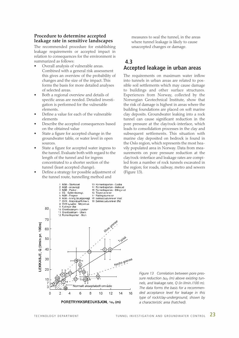
4.3Accepted leakage in urban areasThe requirements on maximum water inflowinto tunnels in urban areas are related to pos-sible soil settlements which may cause damageto buildings and other surface structures.Experiences from Norway, collected by theNorwegian Geotechnical Institute, show thatthe risk of damage is highest in areas where thebuilding foundations are placed on soft marineclay deposits. Groundwater leaking into a rocktunnel can cause significant reduction in thepore pressure at the clay/rock-interface, whichleads to consolidation processes in the clay andsubsequent settlements. This situation withmarine clay deposited on bedrock is found inthe Oslo region, which represents the most hea-vily populated area in Norway. Data from mea-surements on pore pressure reduction at theclay/rock-interface and leakage rates are compi-led from a number of rock tunnels excavated inthe region; for roads, railway, metro and sewers(Figure 13).
Figure 13 Correlation between pore pres-sure reduction ∆uF (m) above existing tun-nels, and leakage rate, Q (in l/min./100 m).The data forms the basis for a recommen-ded acceptance level for leakage in thistype of rock/clay-underground, shown bya characteristic area (hatched).
24 T U N N E L I N V E S T I G AT I O N A N D G R O U N D WAT E R C O N T R O L T E C H N O L O G Y D E PA R T M E N T
From the data in Figure 13 it is possible to pre-dict the pore pressure reduction in clay depositscaused by a tunnel excavation. The data formsthe basis for the recommended procedure toestablish maximum allowable water inflow intoa tunnel. The data indicate that an acceptablelimit to the leakage rate should be 3 - 7litres/minute/ 100 metres tunnel, which corres-ponds to a pore pressure reduction of 1 - 3metres (Figure 13).
The pore pressure reduction decreases with dis-tance from the tunnel, with an average of 2metres per 100 m horizontal distance from thetunnel. The measurements are locally affectedby the thickness of the sediment deposit, sedi-ment types, joints and weakness zones presentin the rock and the extent of cement grouting inthe tunnel. The study shows that systematicgrouting is necessary to fulfil strict leakagerequirements.There is a clear correlation betwe-en the grouting procedures used in the tunnels,the amount of grout cement used, lenght of theboreholes and the resulting hydraulic conducti-vity in the rock above the tunnels. Recentlyexcavated tunnels generally shows better resultsin terms of fulfilled requirements, mainly due toimproved grouting techniques and materials.
The potential for consolidation settlements inthe sediments in relation to pore pressurereduction can be determined from soil samplingand laboratory analyses. Clay deposits generallycontain small amounts of water and thegroundwater table will not be influenced signi-
ficantly by leakage. Drawdown of the ground-water table is shown to occur mainly in areaswhere the clay deposits have a limited extent orwhere the clay deposits are shallow.
An accepted maximum settlement is related tothe value and the type of type structures on thesurface. For example, two major constructionprojects in Oslo have requirements to maximumsettlements in the sediments above the tunnelexcavation sites of 10 mm and 20 mm respecti-vely, in order to keep the possible influence onsurface structures to a minimum.
Procedure to determine accepted lea-kage rate in urban areasThe recommended procedure for estimatingrequirements for leakage rate is based on themeasurements of pore pressure changes in theclay/rock-interface:• Specify accepted maximum consolidation
settlement in the ground above the tunnel• Produce a map of soil cover, type and thick-
ness, along the tunnel• Calculate settlements in terms of pore
pressure changes for any sediment/clay-filled depression identified
• Identify buildings exposed to settlements atthe vulnerable sites, and calculate maxi-mum allowable pore pressure change for this area
• Establish requirements for sealing of the tunnel based on the acceptable pore pressure change above the tunnel.

25T E C H N O L O G Y D E PA R T M E N T T U N N E L I N V E S T I G AT I O N A N D G R O U N D WAT E R C O N T R O L
Techniques for groundwater control are studiedin this project, with the aim of improving con-ventional techniques and development of newmethods. Safe and efficient methods for sealingare of special importance in tunnels with strictrequirements for water ingress.The best methodby far, for sealing rock mass to reduce ground-water ingress to tunnels, is cement groutingahead of the tunnel work face (pre-grouting).The project activities included studies of grou-ting strategies for pre-grouting of tunnels, pro-cedures for both systematic grouting and grou-ting adapted to difficult geological conditionsand complex tunnel design, as well as procedu-res for time efficient grouting. In addition, theproject evaluated natural sealing processes andwater infiltration.
As a result, a specific grouting strategy is syste-matized, based on tests performed on siteduring tunnel excavation, laboratory tests and acompilation and evaluation of grouting perfor-mances in several recently built tunnels. Theimproved grouting strategy is very efficient andgive good control on the amount of wateringress to the tunnel after grouting. Also, thegrout materials used are environmental friendlycements.
A major part of the work in this sub-project wasmonitoring of grouting procedures and practicaltests of grouting strategies in ongoing tunnelconstruction projects: T-baneringen (Metro tun-nel in Oslo), the Jong-Asker railway tunnels andthe road tunnels Hagan and Lunner just northof Oslo.
5.1Laboratory testing of grout cementsLaboratory tests were performed for the docu-mentation of the properties of cement typesused in tunnel grouting, and an evaluation ofthe usefulness of performing laboratory tests on
these materials. Testing of cements was perfor-med by conventional laboratory methods, usingthe actual cement types used in the grouting ofthe Metro tunnel. In summary, the tests showedthat water/cement-ratios (w/c-ratios) higherthan 1.0 result in too long hardening time, thecontrol of the actual w/c-ratio is best done bymeasurements of density, and only freshcements (newly produced) should be used. Testresults gave no indications that the temperatureof the cement during grouting is of importance,but the temperature of the injected rock mayinflict on the hardening process.
A significant part of the project was the con-struction of an apparatus for testing injectionproperties of grout cements. This work was car-ried out by SINTEF. The apparatus consists oftwo parallel glass plates pressed in contact witheach other, one of the plates has tracks whichsimulate joints. Cement suspensions are injec-ted between the glass plates and instrumentsregister the inflow (penetration) capacities ofthe cements. The aim of this test model is toprovide comparative results for different cementtypes, under similar and controlled conditions.The test model was not able to provide resultsduring the time span of the project, but is underfurther development to become ready for com-mercial use.
5.2 Grouting strategies
The project group carried out a test programmein cooperation with the builder and contractorof the Metro tunnel in Oslo, in connection withthe grouting procedures during tunnel excavati-on. The aim was to confirm the grouting techni-que that most efficiently provides sufficient sea-ling of the rock mass.
The Metro tunnel is 1240 m long and part of thenew Metro Ring system in Oslo. The rock over-burden of the tunnel is between 5 and 25
5 Techniques for groundwater control

26 T U N N E L I N V E S T I G AT I O N A N D G R O U N D WAT E R C O N T R O L T E C H N O L O G Y D E PA R T M E N T
metres, and with a cover (0-20 m) of sediments(clay). Due to risk of settlements in the clay cau-sing damage to buildings, the requirements forwater ingress to the tunnel after grouting wasbetween 7 and 14 l/min./100 m, and groutingwas performed for most of the tunnel. The tun-nel was completed in 2002. Tests of materialsand grouting methods were carried out alongdifferent sections of the tunnel construction siteadjusted to the rock mass quality, rock cover anddemands for water inflow (see Figure 14).
Some of the tests and results are listed below:• An evaluation of grouting procedures
proved that systematic pre-grouting of thetunnel is more efficient than sporadic grouting. Sporadic grouting involves adjustment of the procedure based on results from measurements of water leakage in probe holes, and the risk is thatwater will seep towards non-grouted sections of the tunnel. A systematic grouting schedule is both more time efficient and it gives far better and more reliable results.
• A water/cement-ratio lower than 1.0 is necessary to provide rapid and sufficient sealing, the ratio may be as low as 0.5. This
was also confirmed by the laboratory experiments. Silica additives to the grout mix and improved pumping capacity makeinjection of this thick cement grout possible.
• A low water/cement-ratio requires high pressure pumping, up to 10 MPa, which ‘kick’ the grout into the finer joints and assures that the rock mass close to the tunnel is sealed.
• Different types of cement grouts were usedunder similar rock mass conditions and requirements for water ingress. In this particular tunnel, no difference in the results from standard cement and microcement was recorded.
• Tests were performed of optimum groutingtime consumed compared with the total excavation time and the result of grouting,by adjusting the work procedures.The mosttime efficient procedure would be a fast construction progress, with the criteria for water ingress fulfilled from a single round of grouting. The adjustments proved very efficient when working through good rockmass quality and not so strict sealing requirements.
Figure 14 Example of results of the grouting of the Metro tunnel: water leakage and amount of groutcement along the tunnel route. Horizontal lines: red= pre-set requirements for leakage (in l/min./100 m),blue= measured water ingress after grouting. Amount of cement grout used: blue= microcement, red= stan-dard cement.

27T E C H N O L O G Y D E PA R T M E N T T U N N E L I N V E S T I G AT I O N A N D G R O U N D WAT E R C O N T R O L
The procedures which were followed duringexcavation through a particularly difficult weak-ness zone with strong water inflow is also welldocumented. The zone is 50 metres wide andneeded special attention on grouting procedu-res and rock support. The requirements forwater ingress to the tunnel as a whole was ful-filled, with an average of 4.3 l/min./100 m. Theexception was the weakness zone, where waterleakage is up to 8 l/min./100 m. As a result,water- and frost protection measures are redu-ced for parts of the tunnel.
Documentation of grouting procedu-res: mapping of experiencesA selection of eight newly built tunnels (7 inNorway, one in Sweden) are examined withregard to experiences from grouting of the tun-nels. The mapping procedure involved intervi-ews with on-site personel representing bothowners, builders, consultants and contractors.The selection criteria for these tunnels werestrict requirements for water inflow (2-20l/min./100 m), and carefully planned and welldocumented grouting strategies. The experien-ces with different types of rock, the grouting
strategies under various conditions, equipment,materials, performances and final results aremapped and compared. The detailed resultsfrom the mapping is listed in tables which haveproven to be of significant importance whenplanning the grouting strategy for new tunnelconstruction projects.
The general conclusions from the experiencesare comparable to the experiences from theMetro tunnel, such as the advantage of syste-matic, cement-based grouting, low water/cement-ratios and high pressure pumping, aswell as careful supervision of the grouting pro-cedure with adjustments to improve both effici-ency and a safe result. These conclusions formthe basis of the recommended pre-groutingprocedure (‘Active grouting’, see below).
5.3Natural sealing processesIn Norwegian tunnels, water ingress tend todecrease with time. In most cases this couldonly be caused by natural sealing. Laboratory
Figure 15 The Tanum tunnel (Jong-Asker railway). Markings of injection holes in the tunnel work face.

28 T U N N E L I N V E S T I G AT I O N A N D G R O U N D WAT E R C O N T R O L T E C H N O L O G Y D E PA R T M E N T
experiments were carried out by Aquateam withthe aim of tracing the sealing mechanism and tofind out if this mechanism can be put to practi-cal use in tunnels. Water samples from a selecti-on of tunnels were analysed; sub-sea tunnelsand one land tunnel.The main results show thatthe water leaking into the tunnels is rich in par-ticles of iron, and contain lesser amounts of cal-cium, barium and manganese.
Laboratory testing showed that oxygen injectedto sand columns containing Fe2+ caused oxida-tion to Fe3+ and subsequent deposition of theiron, the rate depending on the particle size wit-hin the column. The results of these tests areinteresting, but further tests are needed to findout if water leakages can be reduced by accele-rating natural sealing processes.
5.4Water infiltrationGroundwater infiltration is used to control thepore pressure temporarily during excavation oftunnels. The reduction of pore pressure in sedi-ments due to water leakage into a tunnel maycause settlement and significant damage to thesurface areas and to buildings. In this project,experience from water infiltration over 20-30years is compiled in a report from theNorwegian Geotechnical Institute.
The conclusions from the evaluation are thatinfiltration holes must be placed in bedrock, andestablished as result of good knowledge of thehydraulic conductivity of the rock mass and thenature of sediment deposits. Wells placed insediments are unpredictable and have occasio-nally caused severe problems due to erosion.Furthermore, water infiltration should be usedas a temporary measure during constructiononly. All of the permanent installations that arein use today were not planned as such, and hadto be kept in function due to insufficient sealingof the tunnel or underground structure. Theseinstallations do not guarantee that the porepressure is maintained and are costly due to theunforeseen, long term, ‘indefinite’, operationand maintenance.
5.5Pre-grouting techniquesTheoretical and empirical background for high-pressure groutingA theoretical and empirical background forhigh-pressure grouting is assembled for thisproject by N. Barton and Associates. The reportdescribes the problems, and some solutions,concerning pre-injection in jointed and faultedrock masses ahead of tunnels.The application ofvery high pressure pre-injection for sealing andimproving the stability of tunnels, has focussed
Figure 16 Grouting in the
Hagan tunnel syenite

29T E C H N O L O G Y D E PA R T M E N T T U N N E L I N V E S T I G AT I O N A N D G R O U N D WAT E R C O N T R O L
attention on the need for quantitative explana-tions of grout take volumes and on the effectson the rock mass, of the 5 to 10 MPa injectionpressures. The report provides explanations ofjoint properties and change when the rock massis subjected to high-pressure grouting of thickcement grout.
In conclusion, there is practical evidence andempirically-derived support for increased seis-mic velocities, increased deformation modulus,reduced deformation, reduced permeability, andreduced tunnel support needs as a result of suc-cessful high-pressure pre-injection with stablecement grout.
Rock mass qualityThe quality of the rock mass will determine thechoice of grouting strategy.The rock masses thatare most common in the bedrock of Norway arehere divided into four groups based on experi-ences from engineering geology and their gene-ral properties during grouting. For each group,the number of injection holes, length of holes,water/cement-ratios and cement types arerecommended, as summarized below.
The rock mass is divided into the followingcategories:A. Open joints with little or no clay filling, foundmost frequently in sandstones, quartzites, sye-nites, granites. The hydraulic conductivity of therock mass is relatively high, and the rock masshas low resistance to grouting. In general, fewand long injection holes are used, and lowwater/cement-ratios.B. Jointed rock mass with joints partly filled toproduce local channels. This situation is fre-quently found in gneisses, which represent amajor part of the Norwegian bedrock. The jointsare typically filled with clay minerals weatheredfrom feldspar minerals. The rock mass is lesseasy to grout, and the injection strategy must beadjusted to the local rock mass condition. Theprocedure is generally an initial high w/c-ratio(c. 1.0) and relatively low injection pressures,towards a final low w/c-ratio and high pressurepumping (up to 10 MPa). The high injectionpressure is important in order to establish com-munication between joints.C. Dense, plastic rock masses represented bymetamorphic rocks such as mica schists, phylli-tes and greenschists. Joints are typically filledwith clay, and have small channels occuring onnarrow joints. The hydraulic conductivity of therock mass is low, and grouting may be difficult.
In order to grout the small and scattered chan-nels, many short injection holes are needed. Aninitial high w/c-ratio (c. 0.9) and microcement isused, with a final lower ratio and high pressurepumping.D. Rock masses with extremely open joints as aresult of fault zones or karst. Tunnelling in theserock masses will require extraordinary efforts,for example injection of coarse masses. It isimportant to locate these zones at an early stageso that the grouting procedure may be properlyplanned.
‘Active grouting’A recommended procedure for pre-grouting ispresented, based on the results from this projectcombined with the compilation of well docu-mented and successful grouting results in vari-ous rock masses. The foundation for the appli-cation of this grouting strategy is an understan-ding of rock mass quality, grouting pressures,cement properties, the amount of cement andcement additives used, the geometry of thegrouting fan and the number of injection holesin the tunnel work face.
• Low water/cement-ratio combined with high pressure pumping is the main con-dition for successful grouting.The w/c-ratioshould be as low as practically possible (down to 0.5) in order to obtain a marked pressure loss away from the tunnel. This assures that the cement is concentrated close to the tunnel. The pressure build-up in each separate hole must be constantly surveilled, with adjustments of the w/c-ratio based on the observations. The pressure build-up should increase steadily to allow a smooth cement inflow, and witha final injection pressure as high as is possible (10 MPa is the maximum capacityof most of today’s pumps).
• The type of cement is adjusted to local geological conditions, both standard cement and the fine-grained microcement are used. Additives of superplasticizers andsilica increase the flow stability of the cement grout. It should be noted that withthe cement grout mix and the pump capacity for handling dense masses, there isno longer need for the highly toxic chemical grouts.
• The tunnel is to be grouted from the sole and upward. In this way, the water is pushed up and away from the tunnel. The grouting is most efficient when using many

30 T U N N E L I N V E S T I G AT I O N A N D G R O U N D WAT E R C O N T R O L T E C H N O L O G Y D E PA R T M E N T
holes and as long holes as possible. The holes must be placed both circling the profile and in the centre of the work face.The geometry and the length of the holes in the grouting fan must be adjusted to thelocal conditions. An initial situation with many holes is recommended, with an adjustment based on observations and adaptations to the rock mass condition on the site. Use of modern injection rigs with two or more separate grouting lines increases the efficiency.
• Systematic grouting where the leakage requirements are strict have proven to givethe best results. Where the rock mass quality is favourable, the grouting procedure may be adjusted to a more timeefficient ‘factory’ performance.
• A successful sealing, with little or no waterleakage into the tunnel will reduce the need for water- and frost protection and rock support measures.
• Continuous supervision, control and adjustment of the grouting procedure as well as an experienced professional crew isthe key to a successful result.
In conclusion: It is possible to build technicallyvery complicated tunnels with total control onthe groundwater by using systematic cement-based grouting ahead of the tunnel workingface, based on the principles of active grouting.This is of particular importance in areas wherethe tunnel construction is not to cause unwan-ted environmental consequences.

31T E C H N O L O G Y D E PA R T M E N T T U N N E L I N V E S T I G AT I O N A N D G R O U N D WAT E R C O N T R O L
Norwegian Public Roads Administration (www.vegvesen.no)
National Rail Administration (www.jbv.no)
Geological Survey of Norway (www.ngu.no)
Norwegian Geotechnical Institute (www.ngi.no)
Norconsult AS (www.norconsult.no)
Multiconsult AS (www.multiconsult.no)
Norwegian Institute for Nature Research (www.nina.no)
The Norwegian Centre for Soil and Environmental Research (www.jordforsk.no)
Norwegian University of Science and Technology (www.ntnu.no)
SINTEF (www.sintef.no)
Aquateam (www.aquateam.no)
GeoVita
Geotechnical Peak Technology AS
N. Barton & Associates
Additional funding by:
Research Council of Norway (www.forskningsradet.no)
Oslo City Government
NCC Anlegg AS
Skanska AS
Veidekke ASA
Participating firms in the research and development programme (2000-2003):

32 T U N N E L I N V E S T I G AT I O N A N D G R O U N D WAT E R C O N T R O L T E C H N O L O G Y D E PA R T M E N T

33T E C H N O L O G Y D E PA R T M E N T T U N N E L I N V E S T I G AT I O N A N D G R O U N D WAT E R C O N T R O L
The results from the research programme arepresented in a total of 40 reports, and are sum-marized in five Publications from theNorwegian Public Roads Administration,Directorate of Public Roads (Statens vegvesenVegdirektoratet). These are available inNorwegian only.
Publications:No. 101: A. Palmstrøm, B. Nilsen, K.B. Pedersen & L.Grundt (2003): «Appropriate amount of investi-gations for underground rock constructions».
No. 102: J.S. Rønning (2003): «New geological and geo-physical methods for tunnel investigations».
No. 103: K. Karlsrud, L. Erikstad & P. Snilsberg (2003):«Requirements concerning tunnel leakages andenvironmental aspects»
No. 104: B.H. Klüver & A. Kveen (2004): «Practical pre-grouting»
No. 105: M. Lindstrøm & A. Kveen (2004): «Tunnel inve-stigations and ground water control. Finalreport».
The following three reports are avai-lable in english:Beard, L.P. (2001): Assessment of geophysical anomalies nearLangvatnet, Lunner, Oppland Fylke. Statensvegvesen Teknologiavdelingen. Report no. 2247.
Cuisiat, F., Skurtveit, E. & Kveldsvik, V. (2003):Prediction of leakage into the Lunner tunnelbased on discrete fracture flow models. Statensvegvesen Teknologiavdelingen. Report no. 2318.
Dehls, J.F. & Nordgulen, Ø. (2003): Analysis of INSAR data over Romeriksporten.Statens vegvesen Teknologiavdelingen. Reportno. 2346.
Publications:

34 T U N N E L I N V E S T I G AT I O N A N D G R O U N D WAT E R C O N T R O L T E C H N O L O G Y D E PA R T M E N T

45. Proceedings of the International Research Symposium on Pave-ment Wear, Oslo 6th-9th June 1972. 227 p. 1973.
46. Frost i veg 1972. Nordisk Vegteknisk Forbunds konferanse i Oslo18-19 sept. 1972 (Frost Action on Roads 1972. NVF Conferencein Oslo 1972). 136 p. 1973.
47. Å. KNUTSON. Praktisk bruk av bark i vegbygging (Specifi cationsfor Use of Bark in Highway Engineering).E. GJESSING, S. HAUGEN. Barkavfall – vannforurensning (BarkDeposits – Water Pollution). 23 p. 1973.
48. Sikring av vegtunneler (Security Measures for Road Tunnels). 124p. 1975.
49. H. NOREM. Registrering og bruk av klimadata ved planlegging avhøgfjellsveger (Collection and Use of Weather Data in MountainRoad Planning).H. NOREM. Lokalisering og utforming av veger i driv snøområder(Location and Design of Roads in Snow-drift Areas).H. NOREM, J. G. ANDERSEN. Utforming og plassering av snø-skjermer (Design and Location of Snow Fences).K. G. FIXDAL. Snøskredoverbygg (Snowsheds).H. SOLBERG. Snørydding og snøryddingsutstyr i Troms (WinterMaintenance and Snow Clearing Equipment in Troms County). 59p. 1975.
50. J. P. G. LOCH. Frost heave mechanism and the role of the thermalregime in heave experiments on Norwegian silty soils.K. FLAATE, P. SELNES. Side friction of piles in clay.K. FLAATE, T. PREBER. Stability of road embankments in soft clay.A. SØRLIE. The effect of fabrics on pavement strength – Platebearing tests in the laboratory.S. L. ALFHEIM, A. SØRLIE. Testing and classification of fabricsfor application in road constructions. 48 p. 1977.
51. E. HANSEN. Armering av asfaltdekker (Reinforced bitu minouspavements).T. THURMANN-MOE, R. WOLD. Halvsåling av asfalt dekker(Resurfacing of bituminous pavements).A. GRØNHAUG. Fremtidsperspektiver på fullprofilboring av veg-tunneler (Full face boring of road tunnels in crystalline rocks).E. REINSLETT. Vegers bæreevne vurdert ut fra maksimal nedbøy-ning og krumming (Allowable axle load (technically) as determi-ned by maximum deflection and curvature). 52 p. 1978.
52. T. THURMANN-MOE, S. DØRUM. Lyse vegdekker (High luminanceroad surfaces).A. ARNEVIK, K. LEVIK. Erfaringer med bruk av overflatebehand-linger i Norge (Experiences with surface dressings in Norway).J. M. JOHANSEN. Vegdekkers jevnhet (Road roughness).G. REFSDAL. Vegers bæreevne bestemt ved oppgraving (indeks-metoden) og nedbøyningsmåling. Er metodene gode nok? (Roadbearing capacity as decided by deflection measure ments and theindex method). 44 p. 1980.
53. E. HANSEN, G. REFSDAL, T. THURMANN-MOE. Sur facing for low volume roads in semi arid areas.H. MTANGO. Dry compaction of lateritic gravel.T. THURMANN-MOE. The Otta-surfacing method. Perfor manceand economi.G. REFSDAL. Thermal design of frost proof pavements.R. G. DAHLBERG, G. REFSDAL. Polystyrene foam for lightweightroad embankments.A. SØRLIE. Fabrics in Norwegian road building.O. E. RUUD. Hot applied thermoplastic road marking materials.R. SÆTERSDAL, G. REFSDAL. Frost protection in building con-struction. 58 p. 1981.
54. H. ØSTLID. High clay road embankments.A. GRØNHAUG. Requirements of geological studies for underseatunnels.
K. FLAATE, N. JANBU. Soil exploration in a 500 m deep fjord,Western Norway. 52 p. 1981.
55. K. FLAATE. Cold regions engineering in Norway.H. NOREM. Avalanche hazard, evaluation accuracy and use.H. NOREM. Increasing traffic safety and regularity in snowstormperiods.G. REFSDAL. Bearing capacity survey on the Norwegian roadnetwork method and results.S. DØRUM, J. M. JOHANSEN. Assessment of asphalt pavementcondition for resurfacing decisions.T. THURMANN-MOE. The Otta-surfacing method for improvedgravel road maintenance.R. SÆTERSDAL. Prediction of frost heave of roads.A. GRØNHAUG. Low cost road tunnel developments in Norway.40 p. 1983.
56. R. S. NORDAL. The bearing capacity, a cronic problem in pave-ment engineering?E. REINSLETT. Bearing capacity as a function of pavement deflec-tion and curvature.C. ØVERBY. A comparison between Benkelman beam, DCP andClegg-hammer measurements for pavement strength evaluation.R. S. NORDAL. Detection and prediction of seasonal changes ofthe bearing capacity at the Vormsund test road.P. KONOW HANSEN. Norwegian practice with the ope rationof Dynaflect.G. REFSDAL, C-R WARNINGHOFF. Statistical consider ationsconcerning the spacing between measuring points for bearing capacity measurements.G. REFSDAL, T. S. THOMASSEN. The use of a data bank foraxle load policy planning and strengthening purpose.T. S. THOMASSEN, R. EIRUM. Norwegian practices for axleload restrictions in spring thaw. 80 p. 1983.
57. R. S. NORDAL, E. HANSEN (red.). Vormsund forsøksveg.Del 3: Observasjoner og resultater (Vormsund Test Road, Part 3:Observations and Results). 168 p. 1984.
58. R. S. NORDAL, E. HANSEN (red). The Vormsund Test Road.Part 4: Summary Report. 82 p. 1987.
59. E. LYGREN, T. JØRGENSEN, J. M. JOHANSEN. Vannforurensingfra veger. I. Sammendragsrapport. II. Veiledning for å håndtere de problemer som kan oppstå når en veg kommer i nærheten av drikkevannforekomst (Highway pollu tion). 48 p. 1985.
60. NRRL, ASPHALT SECTION. Surfacings for low volume roads.T. E. FRYDENLUND. Superlight fill materials.K. B. PEDERSEN, J. KROKEBORG. Frost insulation in rock tunnels.H. ØSTLID. Flexible culverts in snow avalanche protection for roads.K. FLAATE. Norwegian fjord crossings why and how.H. S. DEIZ. Investigations for subsea tunnels a case history.H. BEITNES, O. T. BLINDHEIM. Subsea rock tunnels. Prei n vesti-gation and tunnelling processes. 36 p. 1986.
61. Plastic Foam in Road Embankments:T. E. FRYDENLUND. Soft ground problems.Ø. MYHRE. EPS – material specifications.G. REFSDAL. EPS – design considerations.R. AABØE. 13 years of experience with EPS as a lightweight fillmaterial in road embankments.G. REFSDAL. Future trends for EPS use.Appendix: Case histories 1-12. 60 p. 1987.
62. J. M. JOHANSEN, P. K. SENSTAD. Effects of tire pressures on flexi-ble pavement structures – a literature survey. 148 p. 1992.
63. J. A. JUNCA UBIERNA. The amazing Norwegian subsea roadtunnels. 24 p. 1992.
64. A. GRØNHAUG. Miljøtiltak ved vegbygging i bratt terreng (Envi-
Publications from the Technology Department

ronmental measures for road construction in mountain slopes).Ø. MYHRE. Skumplast uten skadelige gasser (The phase out ofhard CFCs in plastic foam).T. JØRGENSEN. Vurdering av helsefare ved asfaltstøv (Evaluationof health risks of dust from asphalt wear).N. RYGG. Miljømessig vegtilpassing (Environmental road adjust-ment). 52 p. 1992.
65. C. HAUCK. The effect of fines on the stability of base gravel.A. A. ANDRESEN, N. RYGG. Rotary-pressure sounding 20 yearsof experience. 24 p. 1992.
66. R. EVENSEN, P. SENSTAD. Distress and damage factors forflexible pavements. 100 p. 1992.
67. STEINMATERIALKOMITEEN. Steinmaterialer (Aggre gates). 20p. 1993.
68. Å. KNUTSON. Frost action in soils. 40 p. 1993.69. J. VASLESTAD. Stål- og betongelementer i løsmasse tunneler
(Corrugated steel culvert and precast elements used for cut andcover tunnels).J. VASLESTAD. Støttekonstruksjoner i armert jord (Rein forcedsoil walls). 56 p. 1993.
70. SINTEF SAMFERDSELSTEKNIKK. Vegbrukers reduserte transport-kostnader ved opphevelse av telerestriksjoner (Redused tran-sportation costs for road user when lifting axle load restrictions during spring thaw period). 144 p. 1993.
71. R. Evensen, E. Wulvik. Beregning av forsterkningsbehov basert påtilstandsvurderinger – analyse av riks- og fylkes vegnettet i Akershus (Estimating the need of strengthening from road perfor-mance data). 112 p. 1994.
72. Fjellbolting (Rockbolting). 124 p. 1994.73. T. BÆKKEN, T. JØRGENSEN. Vannforurensning fra veg – langtids-
effekter (Highway pollution – long term effect on water quality).64 p. 1994.
74. J. VASLESTAD. Load reduction on buried rigid pipes.J. VASLESTAD, T. H. JOHANSEN, W. HOLM. Load reductionon rigid culverts beneath high fills, long-term behaviour.J. VASLESTAD. Long-term behaviour of flexible large-span culverts.68 p. 1994.
75. P. SENSTAD. Sluttrapport for etatsatsingsområdet «Bedre utny-ttelse av vegens bæreevne» («Better utilization of the bearing capasity of roads, final report»). 48 p. 1994.
76. F. FREDRIKSEN, G. HASLE, R. AABØE. Miljøtunnel i Borrekommune (Environmental tunnel in Borre Municipa lity).F. FREDRIKSEN, F. OSET. GEOPLOT – dak-basert presen tasjonav grunnundersøkelser (GEOPLOT – CAD-based presentation ofgeotechnical data). 48 p. 1994.
77. R. KOMPEN. Bruk av glideforskaling til brusøyler og -tårn (Useof slipform for bridge columns and towers). 16 p. 1995.
78. R. KOMPEN. Nye regler for sikring av overdekning (New practicefor ensuring cover).R KOMPEN, G. LIESTØL. Spesifikasjoner for sikring av armeringensoverdekning (Specifications for ensuring cover for reinforcement).40 p. 1995.
79. The 4th international conference on the «Bearing capasity of roads and airfields» – papers from the Norwegian Road ResearchLaboratory. 96 p. 1995.
80. W. ELKEY, E. J. SELLEVOLD. Electrical resistivity of concrete. 36 p.1995.
81. Å. KNUTSON. Stability analysis for road construction. 48 p. 1995.82. A. ARNEVIK, E. WULVIK. Erfaringer med SPS-kontrakter for asfal-
tering i Akershus (Experiences with wear-guaranteed asphalt con-tracts on high volume roads in Akershus county). 28 p. 1996.
83. Sluttrapport for etatsatsingsområdet «Teknisk utvikling innen bru og tunnelbygging» («Technical development – bridge and tunnelconstruction, final report»). 20 p. 1996.
84. OFU Gimsøystraumen bru. Sluttrapport «Prøvereparasjon og produktutvikling» («Trail repairs and product development, final report»). 156 p. 1997.
85. OFU Gimsøystramen bru. Sluttrapport «Klimapåkjenning og til-standsvurdering» («Climatic loads and condition assessment,final report»). 248 p. 1998.
86. OFU Gimsøystraumen bru. Sluttrapport «Instrumentering, doku-mentasjon og verifikasjon» («Instrumen tation, documentation and verification, final report») 100 p. 1998.
87. OFU Gimsøystraumen bru. Anbefalinger for inspeksjon, reparasjonog overflatebehandling av kystbruer i betong (Recommendations for inpection, repair and surface treatment of costal concrete bridges). 112 p. 1998.
88. OFU Gimsøystraumen bru. Anbefalinger for instrumentert korro-sjonsovervåknning av kystbruer i betong. (Recommendations for instrumental corrosion monitoring of costal concrete bridges). 60 p. 1998
89. OFU Gimsøystraumen bru. Hovedresultater og oversikt over slutt-dokumentasjon (Main result and overwiew of project reports). 24p. 1998.
90. J. KROKEBORG. Sluttrapport for Veg-grepsprosjektet «Veggrep på vinterveg» («Studded tyres and public health, final report». 52 p.1998.
91. A. GRØNHAUG. Tunnelkledinger (Linings for water and frost pro-tection of road tunnels). 68 p. 1998.
92. J. K. LOFTHAUG, J. MYRE, F. H. SKAARDAL, R. TELLE. Asfaltutvik-lingsprosjektet i Telemark (Cold mix project in Telemark). 68 p.1998.
93. C. ØVERBY. A guide to the use of Otta Seals. 52 p. 1999.94. I. STORÅS et al.: Prosjektet HMS – sprøytebetong (Fullscale
testing of alkali-free accelarators). 64 p. 1999.95. E. WULVIK, O. SIMONSEN, J. M. JOHANSEN, R. EVENSEN,
B. GREGER. Funksjonskontrakt for lav trafikkveg: Rv 169,Stensrud–Midtskog, Akershus, 1994–1999 (Performance-contract for the low traffic road Rv 169). 40 p. 2000.
96. Estetisk utforming av vegtunneler (Aesthetic design of road tunnels). 64 p. 2000.
97. K. I. DAVIK, H. BUVIK. Samfunnstjenlige vegtunneler 1998–2001 (Tunnels for the citizen, final report). Sluttrapport. 94 p. 2001.
98. K. MELBY et al. Subsea road tunnels in Norway. 28 p. 2002.99. J. VASLESTAD. Jordnagling (Soil nailing). 52 p. 2002.100.T. E. FRYDENLUND, R. AABØE et al. Lightweight filling materials
for road construction. 56 p. 2002.101.A. PALMSTRØM, B. NILSEN, K. BORGE PEDERSEN, L. GRUNDT.
Miljø- og samfunnstjenlige tunneler; Riktig omfang av undersø-kelser for berganlegg (Appropriate amount of investigations for underground rock constructions). 134 p. 2003.
102.J. S. RØNNING. Miljø og samfunnstjenlige tunneler; Delprosjekt A,Forundersøkelser – Sluttrapport (New geological and geophysical metods for tunnel investigations). 68 p. 2003.
103.K. KARLSRUD, L. ERIKSTAD, P. SNILSBERG. Undersøkelser og krav til innlekkasje for å ivareta ytre miljø (Requirements concerning tunnel leakages and environmental aspects). 100 p. 2003.
104.B. H. KLÜVER, A. KVEEN. Berginjeksjon i praksis (Practical pre-grouting). 68 p. 2004.
105.M. LINDSTRØM, A. KVEEN. Miljø- og samfunnstjenlige tunneler – Sluttrapport (Tunnel investigations and ground water control.Final report). 74 p. 2004.
106.T. BÆKKEN, P. J. FÆRØVIG. Effekter av vegforurensninger på vannkvalitet og biologi i Padderudvann (The effects of highway pollution on water quality and biology in Lake Padderud). 92 p.2004.
107.M. LINDSTRØM, A. KVEEN. Tunnel investigation and ground watercontrol. 35 p. 2005.
108. Ø. MYHRE (red.). Frost i jord 2005 (Frost in Ground 2005). 80 p.2005.

The Norwegian Directorate of Public Roads,Technology Department
Postal address:
Norwegian Public Roads
Administration,
Directorate of Public Roads,
Technology Department,
P.O. Box 8142 Dep,
N-0033 Oslo, Norway
Office address in Oslo: Brynsengfaret 6AOffice address in Trondheim: Abels gate 5E-mail: [email protected]
www.vegvesen.no
SOIL MECHANICS AND TUNNEL TECHNOLOGY SECTION
MATERIALS TECHNOLOGY SECTION
BRIDGE TECHNOLOGY SECTION
ADMINISTRATION
Telephone +47 22073500
CENTRE FOR ROAD AND TRAFFIC TECHNOLOGY
Telephone +47 73954630
Postal address:
Norwegian Public Roads
Administration,
Directorate of Public Roads,
Technology Department,
P.O. Box 8142 Dep,
N-0033 Oslo, Norway
omslag-107.qxd 16-12-05 10:21 Side 2
PUBL ICAT ION Techno logy Depar tment
Tunnel investigation andgroundwater control
no. 107
Norwegian Public Roads AdministrationDirectorate of Public Roads
P.O. Box 8142 DepN-0033 Oslo
Telephone +47 22073500Fax +47 22073768
E-mail: [email protected]
ISSN 1504-5064
omslag-107.qxd 16-12-05 10:21 Side 1