Embed Size (px)
Citation preview
Journal of Geomatics Vol 11 No. 2 October 2017
© Indian Society of Geomatics
Tunnel engineering survey at Delhi metro phase-III CC04 project
G. Jagadeswara Rao
CEC-CICI Jv, Delhi Metro Phase-III CC04 Project
Email: [email protected]
(Received: May 17, 2017; in final form: Sep 22, 2017)
Abstract: Tunnel Boring Machines (TBMs) are used to excavate tunnels in virtually all types of grounds and under
widely different physical conditions. The history of TBMs started with soft ground shields of the type developed in
England. These shields progressed by breaking the excavation in to small compartments excavated by hand. The
science of mechanical underground tunnel excavation has developed continual step by step. TBMs, also known as
Moles, are the recent development in the tunnel driven techniques. High precision survey is very essential for a TBM
to ensure the excavation and build the tunnel, within the construction limits and tolerances, according to the Designed
Tunnel Axis (DTA). TBM guidance system provides all the very important information, which is absolutely necessary
to drive the TBM along DTA by continuous tracking the position during mining/excavation and display both numerical
and graphical display the position of the TBM in the pilot cabin to control / steer the machine. In the paper, surveying
technology adopted in the Delhi metro phase III (CC-04) project in the Metro City Delhi in the year 2013-2017 is
described.
Keywords: EPBM, Guidance system, Double zigzag traverse
1. Introduction
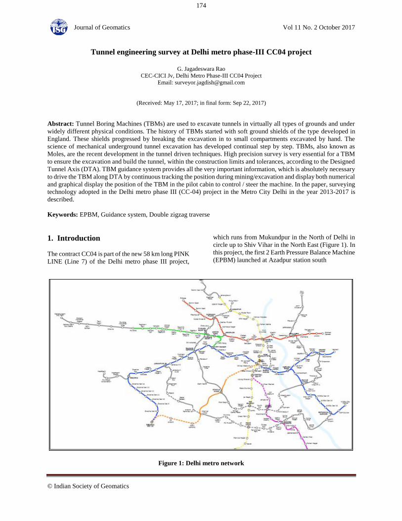
The contract CC04 is part of the new 58 km long PINK
LINE (Line 7) of the Delhi metro phase III project,
which runs from Mukundpur in the North of Delhi in
circle up to Shiv Vihar in the North East (Figure 1). In
this project, the first 2 Earth Pressure Balance Machine
(EPBM) launched at Azadpur station south
Figure 1: Delhi metro network
174
Journal of Geomatics Vol 11 No. 2 October 2017
Shaft were moved towards Shalimarbagh station.
After the breakthrough at Shalimarbagh station North
end, both the machines were dismantled and shifted to
North end of Azadpur station and relaunched for
Tunnel from Azadpur to Mukudpur, due to unforeseen
ground condition, both the machines got stuck at
midway of the alignment. So 2 additional EPBMs
were launched at Mukundpur Ramp to complete the
tunnelling between Azadpur to Mukundpur (Figure 2).
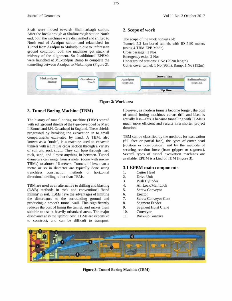
2. Scope of work
The scope of the work consists of:
Tunnel: 5.2 km bored tunnels with ID 5.80 meters
(using 4 TBM EPB Mode)
Cross passage: 1 Nos
Emergency exits: 2 Nos
Underground stations: 1 No (252m length)
Cut & cover tunnel: 1 No (96m), Ramp: 1 No (192m)
Figure 2: Work area
3. Tunnel Boring Machine (TBM)
The history of tunnel boring machine (TBM) started
with soft ground shields of the type developed by Marc
I. Brunel and J.H. Greathead in England. These shields
progressed by breaking the excavation in to small
compartments excavated by hand. A TBM, also
known as a "mole", is a machine used to excavate
tunnels with a circular cross section through a variety
of soil and rock strata. They can bore through hard
rock, sand, and almost anything in between. Tunnel
diameters can range from a meter (done with micro-
TBMs) to almost 16 meters. Tunnels of less than a
metre or so in diameter are typically done using
trenchless construction methods or horizontal
directional drilling rather than TBMs.
TBM are used as an alternative to drilling and blasting
(D&B) methods in rock and conventional 'hand
mining' in soil. TBMs have the advantages of limiting
the disturbance to the surrounding ground and
producing a smooth tunnel wall. This significantly
reduces the cost of lining the tunnel, and makes them
suitable to use in heavily urbanized areas. The major
disadvantage is the upfront cost. TBMs are expensive
to construct, and can be difficult to transport.
However, as modern tunnels become longer, the cost
of tunnel boring machines versus drill and blast is
actually less—this is because tunnelling with TBMs is
much more efficient and results in a shorter project
duration.
TBM can be classified by the methods for excavation
(full face or partial face), the types of cutter head
(rotation or non-rotation), and by the methods of
securing reaction force (from gripper or segment).
Several types of tunnel excavation machines are
available. EPBM is a kind of TBM (Figure 3).
3.1 EPBM main components 1. Cutter Head
2. Drive Unit
3. Push Cylinder
4. Air Lock/Man Lock
5. Screw Conveyor
6. Erector
7. Screw Conveyor Gate
8. Segment Feeder
9. Segment Hoist Crane
10. Conveyor
11. Back-up Gantries
Figure 3: Tunnel Boring Machine (TBM)
175
Journal of Geomatics Vol 11 No. 2 October 2017
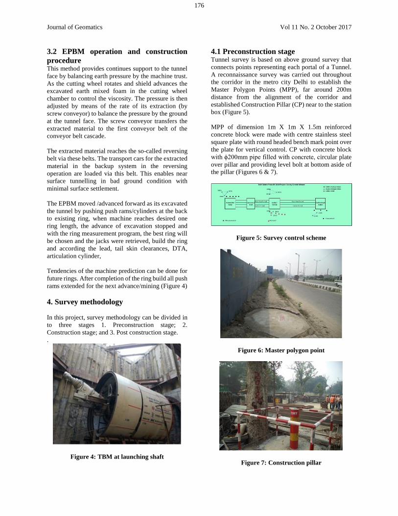
3.2 EPBM operation and construction
procedure This method provides continues support to the tunnel
face by balancing earth pressure by the machine trust.
As the cutting wheel rotates and shield advances the
excavated earth mixed foam in the cutting wheel
chamber to control the viscosity. The pressure is then
adjusted by means of the rate of its extraction (by
screw conveyor) to balance the pressure by the ground
at the tunnel face. The screw conveyor transfers the
extracted material to the first conveyor belt of the
conveyor belt cascade.
The extracted material reaches the so-called reversing
belt via these belts. The transport cars for the extracted
material in the backup system in the reversing
operation are loaded via this belt. This enables near
surface tunnelling in bad ground condition with
minimal surface settlement.
The EPBM moved /advanced forward as its excavated
the tunnel by pushing push rams/cylinders at the back
to existing ring, when machine reaches desired one
ring length, the advance of excavation stopped and
with the ring measurement program, the best ring will
be chosen and the jacks were retrieved, build the ring
and according the lead, tail skin clearances, DTA,
articulation cylinder,
Tendencies of the machine prediction can be done for
future rings. After completion of the ring build all push
rams extended for the next advance/mining (Figure 4)
4. Survey methodology
In this project, survey methodology can be divided in
to three stages 1. Preconstruction stage; 2.
Construction stage; and 3. Post construction stage.
.
Figure 4: TBM at launching shaft
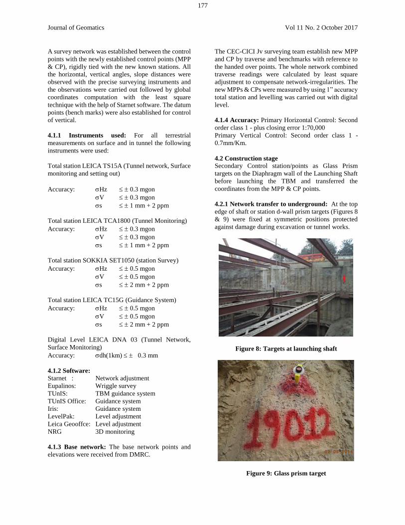
4.1 Preconstruction stage Tunnel survey is based on above ground survey that
connects points representing each portal of a Tunnel.
A reconnaissance survey was carried out throughout
the corridor in the metro city Delhi to establish the
Master Polygon Points (MPP), far around 200m
distance from the alignment of the corridor and
established Construction Pillar (CP) near to the station
box (Figure 5).
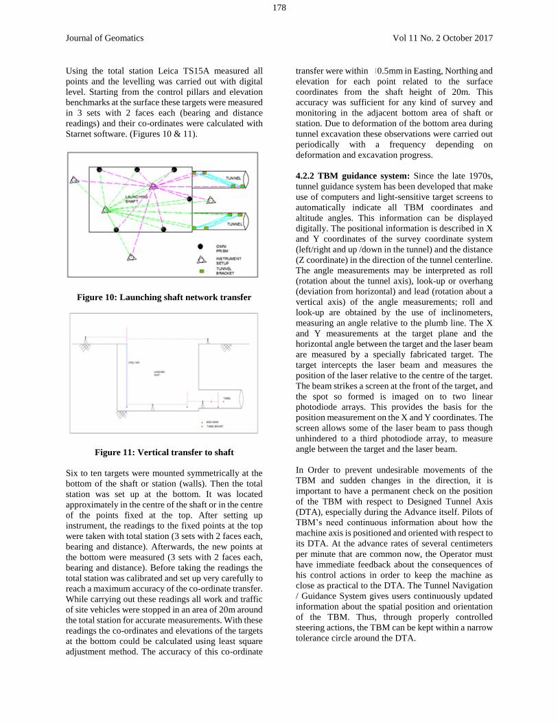
MPP of dimension 1m X 1m X 1.5m reinforced
concrete block were made with centre stainless steel
square plate with round headed bench mark point over
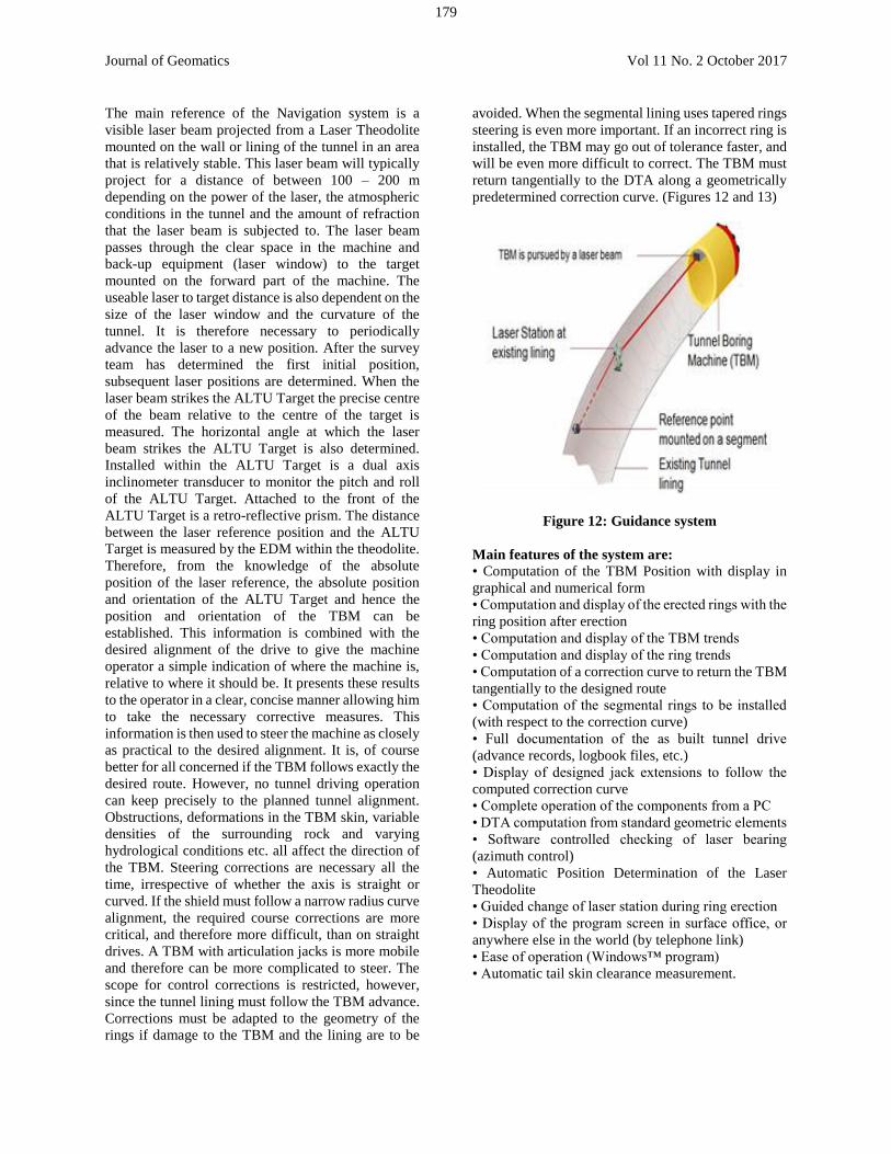
the plate for vertical control. CP with concrete block
with ϕ200mm pipe filled with concrete, circular plate
over pillar and providing level bolt at bottom aside of
the pillar (Figures 6 & 7).
Figure 5: Survey control scheme
Figure 6: Master polygon point
Figure 7: Construction pillar
176
Journal of Geomatics Vol 11 No. 2 October 2017
A survey network was established between the control
points with the newly established control points (MPP
& CP), rigidly tied with the new known stations. All
the horizontal, vertical angles, slope distances were
observed with the precise surveying instruments and
the observations were carried out followed by global
coordinates computation with the least square
technique with the help of Starnet software. The datum
points (bench marks) were also established for control
of vertical.
4.1.1 Instruments used: For all terrestrial
measurements on surface and in tunnel the following
instruments were used:
Total station LEICA TS15A (Tunnel network, Surface
monitoring and setting out)
Accuracy: Hz 0.3 mgon
V 0.3 mgon
s 1 mm + 2 ppm
Total station LEICA TCA1800 (Tunnel Monitoring)
Accuracy: Hz 0.3 mgon
V 0.3 mgon
s 1 mm + 2 ppm
Total station SOKKIA SET1050 (station Survey)
Accuracy: Hz 0.5 mgon
V 0.5 mgon
s 2 mm + 2 ppm
Total station LEICA TC15G (Guidance System)
Accuracy: Hz 0.5 mgon
V 0.5 mgon
s 2 mm + 2 ppm
Digital Level LEICA DNA 03 (Tunnel Network,
Surface Monitoring)
Accuracy: dh(1km) 0.3 mm
4.1.2 Software:
Starnet : Network adjustment
Eupalinos: Wriggle survey
TUnIS: TBM guidance system
TUnIS Office: Guidance system
Iris: Guidance system
LevelPak: Level adjustment
Leica Geooffce: Level adjustment
NRG 3D monitoring
4.1.3 Base network: The base network points and
elevations were received from DMRC.
The CEC-CICI Jv surveying team establish new MPP
and CP by traverse and benchmarks with reference to
the handed over points. The whole network combined
traverse readings were calculated by least square
adjustment to compensate network-irregularities. The
new MPPs & CPs were measured by using 1” accuracy
total station and levelling was carried out with digital
level.
4.1.4 Accuracy: Primary Horizontal Control: Second
order class 1 - plus closing error 1:70,000
Primary Vertical Control: Second order class 1 -
0.7mm/Km.
4.2 Construction stage
Secondary Control station/points as Glass Prism
targets on the Diaphragm wall of the Launching Shaft
before launching the TBM and transferred the
coordinates from the MPP & CP points.
4.2.1 Network transfer to underground: At the top
edge of shaft or station d-wall prism targets (Figures 8
& 9) were fixed at symmetric positions protected
against damage during excavation or tunnel works.
Figure 8: Targets at launching shaft
Figure 9: Glass prism target
177
Journal of Geomatics Vol 11 No. 2 October 2017
Using the total station Leica TS15A measured all
points and the levelling was carried out with digital
level. Starting from the control pillars and elevation
benchmarks at the surface these targets were measured
in 3 sets with 2 faces each (bearing and distance
readings) and their co-ordinates were calculated with
Starnet software. (Figures 10 & 11).
Figure 10: Launching shaft network transfer
Figure 11: Vertical transfer to shaft
Six to ten targets were mounted symmetrically at the
bottom of the shaft or station (walls). Then the total
station was set up at the bottom. It was located
approximately in the centre of the shaft or in the centre
of the points fixed at the top. After setting up
instrument, the readings to the fixed points at the top
were taken with total station (3 sets with 2 faces each,
bearing and distance). Afterwards, the new points at
the bottom were measured (3 sets with 2 faces each,
bearing and distance). Before taking the readings the
total station was calibrated and set up very carefully to
reach a maximum accuracy of the co-ordinate transfer.
While carrying out these readings all work and traffic
of site vehicles were stopped in an area of 20m around
the total station for accurate measurements. With these
readings the co-ordinates and elevations of the targets
at the bottom could be calculated using least square
adjustment method. The accuracy of this co-ordinate
transfer were within 0.5mm in Easting, Northing and
elevation for each point related to the surface
coordinates from the shaft height of 20m. This
accuracy was sufficient for any kind of survey and
monitoring in the adjacent bottom area of shaft or
station. Due to deformation of the bottom area during
tunnel excavation these observations were carried out
periodically with a frequency depending on
deformation and excavation progress.
4.2.2 TBM guidance system: Since the late 1970s,
tunnel guidance system has been developed that make
use of computers and light-sensitive target screens to
automatically indicate all TBM coordinates and
altitude angles. This information can be displayed
digitally. The positional information is described in X
and Y coordinates of the survey coordinate system
(left/right and up /down in the tunnel) and the distance
(Z coordinate) in the direction of the tunnel centerline.
The angle measurements may be interpreted as roll
(rotation about the tunnel axis), look-up or overhang
(deviation from horizontal) and lead (rotation about a
vertical axis) of the angle measurements; roll and
look-up are obtained by the use of inclinometers,
measuring an angle relative to the plumb line. The X
and Y measurements at the target plane and the
horizontal angle between the target and the laser beam
are measured by a specially fabricated target. The
target intercepts the laser beam and measures the
position of the laser relative to the centre of the target.
The beam strikes a screen at the front of the target, and
the spot so formed is imaged on to two linear
photodiode arrays. This provides the basis for the
position measurement on the X and Y coordinates. The
screen allows some of the laser beam to pass though
unhindered to a third photodiode array, to measure
angle between the target and the laser beam.
In Order to prevent undesirable movements of the
TBM and sudden changes in the direction, it is
important to have a permanent check on the position
of the TBM with respect to Designed Tunnel Axis
(DTA), especially during the Advance itself. Pilots of
TBM’s need continuous information about how the
machine axis is positioned and oriented with respect to
its DTA. At the advance rates of several centimeters
per minute that are common now, the Operator must
have immediate feedback about the consequences of
his control actions in order to keep the machine as
close as practical to the DTA. The Tunnel Navigation
/ Guidance System gives users continuously updated
information about the spatial position and orientation
of the TBM. Thus, through properly controlled
steering actions, the TBM can be kept within a narrow
tolerance circle around the DTA.
178
Journal of Geomatics Vol 11 No. 2 October 2017
The main reference of the Navigation system is a
visible laser beam projected from a Laser Theodolite
mounted on the wall or lining of the tunnel in an area
that is relatively stable. This laser beam will typically
project for a distance of between 100 – 200 m
depending on the power of the laser, the atmospheric
conditions in the tunnel and the amount of refraction
that the laser beam is subjected to. The laser beam
passes through the clear space in the machine and
back-up equipment (laser window) to the target
mounted on the forward part of the machine. The
useable laser to target distance is also dependent on the
size of the laser window and the curvature of the
tunnel. It is therefore necessary to periodically
advance the laser to a new position. After the survey
team has determined the first initial position,
subsequent laser positions are determined. When the
laser beam strikes the ALTU Target the precise centre
of the beam relative to the centre of the target is
measured. The horizontal angle at which the laser
beam strikes the ALTU Target is also determined.
Installed within the ALTU Target is a dual axis
inclinometer transducer to monitor the pitch and roll
of the ALTU Target. Attached to the front of the
ALTU Target is a retro-reflective prism. The distance
between the laser reference position and the ALTU
Target is measured by the EDM within the theodolite.
Therefore, from the knowledge of the absolute
position of the laser reference, the absolute position
and orientation of the ALTU Target and hence the
position and orientation of the TBM can be
established. This information is combined with the
desired alignment of the drive to give the machine
operator a simple indication of where the machine is,
relative to where it should be. It presents these results
to the operator in a clear, concise manner allowing him
to take the necessary corrective measures. This
information is then used to steer the machine as closely
as practical to the desired alignment. It is, of course
better for all concerned if the TBM follows exactly the
desired route. However, no tunnel driving operation
can keep precisely to the planned tunnel alignment.
Obstructions, deformations in the TBM skin, variable
densities of the surrounding rock and varying
hydrological conditions etc. all affect the direction of
the TBM. Steering corrections are necessary all the
time, irrespective of whether the axis is straight or
curved. If the shield must follow a narrow radius curve
alignment, the required course corrections are more
critical, and therefore more difficult, than on straight
drives. A TBM with articulation jacks is more mobile
and therefore can be more complicated to steer. The
scope for control corrections is restricted, however,
since the tunnel lining must follow the TBM advance.
Corrections must be adapted to the geometry of the
rings if damage to the TBM and the lining are to be
avoided. When the segmental lining uses tapered rings
steering is even more important. If an incorrect ring is
installed, the TBM may go out of tolerance faster, and
will be even more difficult to correct. The TBM must
return tangentially to the DTA along a geometrically
predetermined correction curve. (Figures 12 and 13)
Figure 12: Guidance system
Main features of the system are:
• Computation of the TBM Position with display in
graphical and numerical form
• Computation and display of the erected rings with the
ring position after erection
• Computation and display of the TBM trends
• Computation and display of the ring trends
• Computation of a correction curve to return the TBM
tangentially to the designed route
• Computation of the segmental rings to be installed
(with respect to the correction curve)
• Full documentation of the as built tunnel drive
(advance records, logbook files, etc.)
• Display of designed jack extensions to follow the
computed correction curve
• Complete operation of the components from a PC
• DTA computation from standard geometric elements
• Software controlled checking of laser bearing
(azimuth control)
• Automatic Position Determination of the Laser
Theodolite
• Guided change of laser station during ring erection
• Display of the program screen in surface office, or
anywhere else in the world (by telephone link)
• Ease of operation (Windows™ program)
• Automatic tail skin clearance measurement.
179
Journal of Geomatics Vol 11 No. 2 October 2017
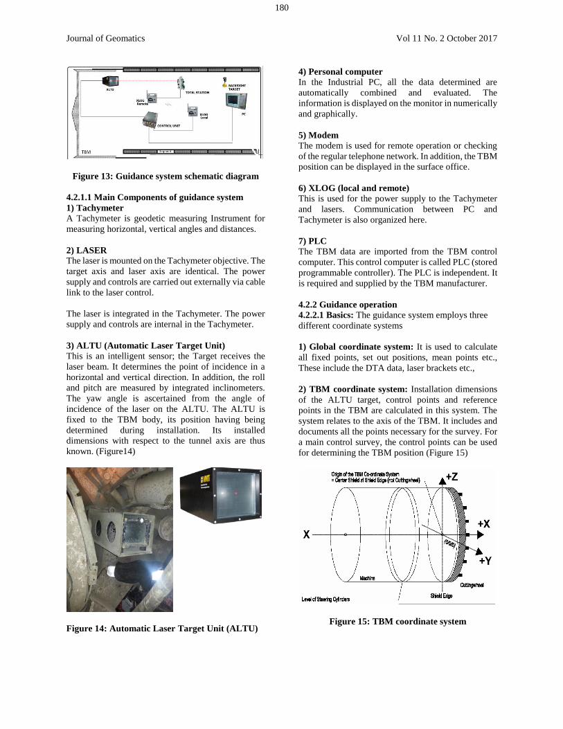
Figure 13: Guidance system schematic diagram
4.2.1.1 Main Components of guidance system
1) Tachymeter
A Tachymeter is geodetic measuring Instrument for
measuring horizontal, vertical angles and distances.
2) LASER
The laser is mounted on the Tachymeter objective. The
target axis and laser axis are identical. The power
supply and controls are carried out externally via cable
link to the laser control.
The laser is integrated in the Tachymeter. The power
supply and controls are internal in the Tachymeter.
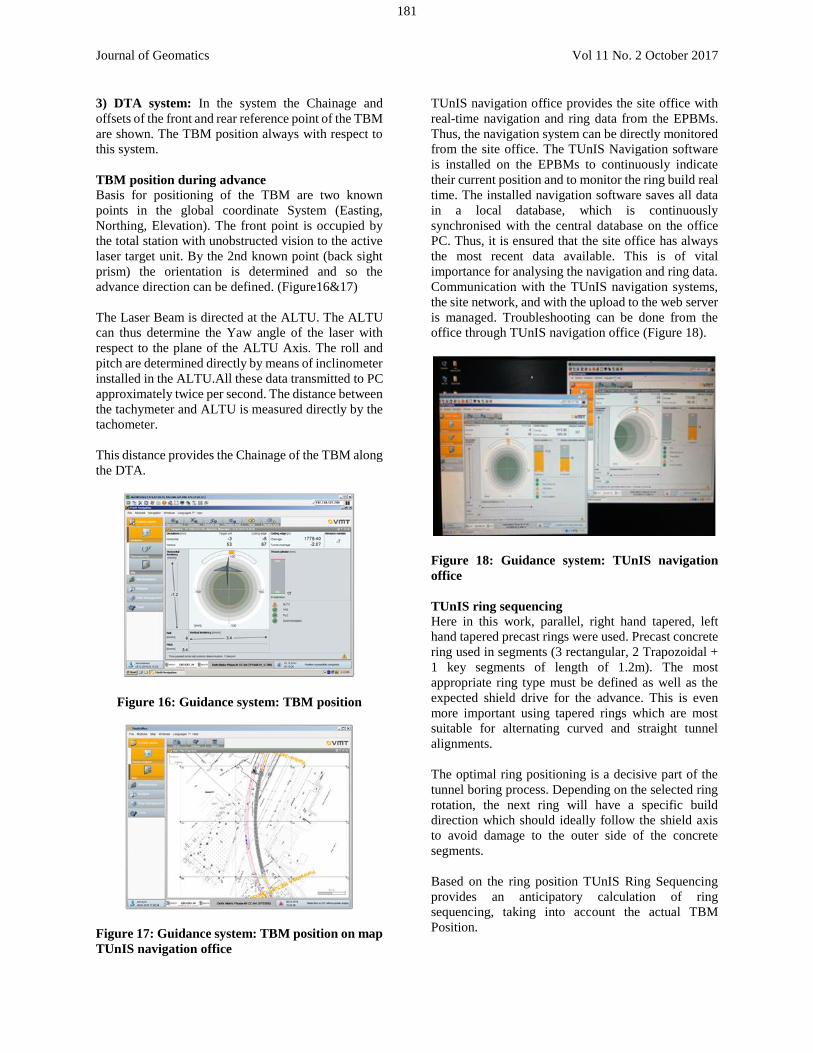
3) ALTU (Automatic Laser Target Unit)
This is an intelligent sensor; the Target receives the
laser beam. It determines the point of incidence in a
horizontal and vertical direction. In addition, the roll
and pitch are measured by integrated inclinometers.
The yaw angle is ascertained from the angle of
incidence of the laser on the ALTU. The ALTU is
fixed to the TBM body, its position having being
determined during installation. Its installed
dimensions with respect to the tunnel axis are thus
known. (Figure14)
Figure 14: Automatic Laser Target Unit (ALTU)
4) Personal computer
In the Industrial PC, all the data determined are
automatically combined and evaluated. The
information is displayed on the monitor in numerically
and graphically.
5) Modem
The modem is used for remote operation or checking
of the regular telephone network. In addition, the TBM
position can be displayed in the surface office.
6) XLOG (local and remote)
This is used for the power supply to the Tachymeter
and lasers. Communication between PC and
Tachymeter is also organized here.
7) PLC
The TBM data are imported from the TBM control
computer. This control computer is called PLC (stored
programmable controller). The PLC is independent. It
is required and supplied by the TBM manufacturer.
4.2.2 Guidance operation
4.2.2.1 Basics: The guidance system employs three
different coordinate systems
1) Global coordinate system: It is used to calculate
all fixed points, set out positions, mean points etc.,
These include the DTA data, laser brackets etc.,
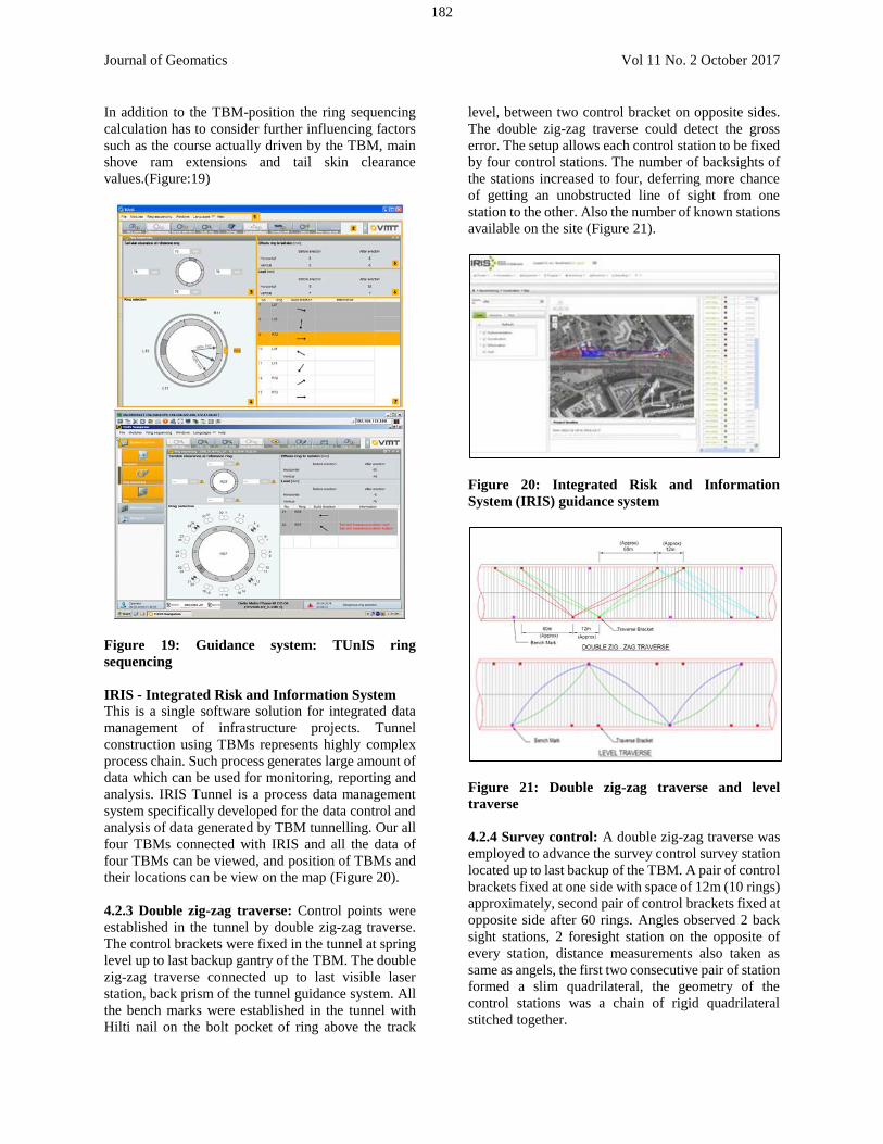
2) TBM coordinate system: Installation dimensions
of the ALTU target, control points and reference
points in the TBM are calculated in this system. The
system relates to the axis of the TBM. It includes and
documents all the points necessary for the survey. For
a main control survey, the control points can be used
for determining the TBM position (Figure 15)
Figure 15: TBM coordinate system
180
Journal of Geomatics Vol 11 No. 2 October 2017
3) DTA system: In the system the Chainage and
offsets of the front and rear reference point of the TBM
are shown. The TBM position always with respect to
this system.
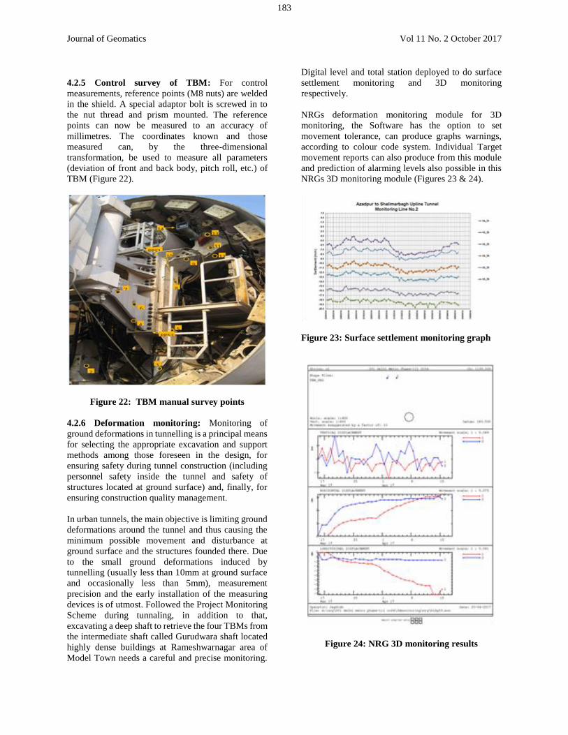
TBM position during advance
Basis for positioning of the TBM are two known
points in the global coordinate System (Easting,
Northing, Elevation). The front point is occupied by
the total station with unobstructed vision to the active
laser target unit. By the 2nd known point (back sight
prism) the orientation is determined and so the
advance direction can be defined. (Figure16&17)
The Laser Beam is directed at the ALTU. The ALTU
can thus determine the Yaw angle of the laser with
respect to the plane of the ALTU Axis. The roll and
pitch are determined directly by means of inclinometer
installed in the ALTU.All these data transmitted to PC
approximately twice per second. The distance between
the tachymeter and ALTU is measured directly by the
tachometer.
This distance provides the Chainage of the TBM along
the DTA.
Figure 16: Guidance system: TBM position
Figure 17: Guidance system: TBM position on map
TUnIS navigation office
TUnIS navigation office provides the site office with
real-time navigation and ring data from the EPBMs.
Thus, the navigation system can be directly monitored
from the site office. The TUnIS Navigation software
is installed on the EPBMs to continuously indicate
their current position and to monitor the ring build real
time. The installed navigation software saves all data
in a local database, which is continuously
synchronised with the central database on the office
PC. Thus, it is ensured that the site office has always
the most recent data available. This is of vital
importance for analysing the navigation and ring data.
Communication with the TUnIS navigation systems,
the site network, and with the upload to the web server
is managed. Troubleshooting can be done from the
office through TUnIS navigation office (Figure 18).
Figure 18: Guidance system: TUnIS navigation
office
TUnIS ring sequencing
Here in this work, parallel, right hand tapered, left
hand tapered precast rings were used. Precast concrete
ring used in segments (3 rectangular, 2 Trapozoidal +
1 key segments of length of 1.2m). The most
appropriate ring type must be defined as well as the
expected shield drive for the advance. This is even
more important using tapered rings which are most
suitable for alternating curved and straight tunnel
alignments.
The optimal ring positioning is a decisive part of the
tunnel boring process. Depending on the selected ring
rotation, the next ring will have a specific build
direction which should ideally follow the shield axis
to avoid damage to the outer side of the concrete
segments.
Based on the ring position TUnIS Ring Sequencing
provides an anticipatory calculation of ring
sequencing, taking into account the actual TBM
Position.
181
Journal of Geomatics Vol 11 No. 2 October 2017
In addition to the TBM-position the ring sequencing
calculation has to consider further influencing factors
such as the course actually driven by the TBM, main
shove ram extensions and tail skin clearance
values.(Figure:19)
Figure 19: Guidance system: TUnIS ring
sequencing
IRIS - Integrated Risk and Information System
This is a single software solution for integrated data
management of infrastructure projects. Tunnel
construction using TBMs represents highly complex
process chain. Such process generates large amount of
data which can be used for monitoring, reporting and
analysis. IRIS Tunnel is a process data management
system specifically developed for the data control and
analysis of data generated by TBM tunnelling. Our all
four TBMs connected with IRIS and all the data of
four TBMs can be viewed, and position of TBMs and
their locations can be view on the map (Figure 20).
4.2.3 Double zig-zag traverse: Control points were
established in the tunnel by double zig-zag traverse.
The control brackets were fixed in the tunnel at spring
level up to last backup gantry of the TBM. The double
zig-zag traverse connected up to last visible laser
station, back prism of the tunnel guidance system. All
the bench marks were established in the tunnel with
Hilti nail on the bolt pocket of ring above the track
level, between two control bracket on opposite sides.
The double zig-zag traverse could detect the gross
error. The setup allows each control station to be fixed
by four control stations. The number of backsights of
the stations increased to four, deferring more chance
of getting an unobstructed line of sight from one
station to the other. Also the number of known stations
available on the site (Figure 21).
Figure 20: Integrated Risk and Information
System (IRIS) guidance system
Figure 21: Double zig-zag traverse and level
traverse
4.2.4 Survey control: A double zig-zag traverse was
employed to advance the survey control survey station
located up to last backup of the TBM. A pair of control
brackets fixed at one side with space of 12m (10 rings)
approximately, second pair of control brackets fixed at
opposite side after 60 rings. Angles observed 2 back
sight stations, 2 foresight station on the opposite of
every station, distance measurements also taken as
same as angels, the first two consecutive pair of station
formed a slim quadrilateral, the geometry of the
control stations was a chain of rigid quadrilateral
stitched together.
182
Journal of Geomatics Vol 11 No. 2 October 2017
4.2.5 Control survey of TBM: For control
measurements, reference points (M8 nuts) are welded
in the shield. A special adaptor bolt is screwed in to
the nut thread and prism mounted. The reference
points can now be measured to an accuracy of
millimetres. The coordinates known and those
measured can, by the three-dimensional
transformation, be used to measure all parameters
(deviation of front and back body, pitch roll, etc.) of
TBM (Figure 22).
Figure 22: TBM manual survey points
4.2.6 Deformation monitoring: Monitoring of
ground deformations in tunnelling is a principal means
for selecting the appropriate excavation and support
methods among those foreseen in the design, for
ensuring safety during tunnel construction (including
personnel safety inside the tunnel and safety of
structures located at ground surface) and, finally, for
ensuring construction quality management.
In urban tunnels, the main objective is limiting ground
deformations around the tunnel and thus causing the
minimum possible movement and disturbance at
ground surface and the structures founded there. Due
to the small ground deformations induced by
tunnelling (usually less than 10mm at ground surface
and occasionally less than 5mm), measurement
precision and the early installation of the measuring
devices is of utmost. Followed the Project Monitoring
Scheme during tunnaling, in addition to that,
excavating a deep shaft to retrieve the four TBMs from
the intermediate shaft called Gurudwara shaft located
highly dense buildings at Rameshwarnagar area of
Model Town needs a careful and precise monitoring.
Digital level and total station deployed to do surface settlement monitoring and 3D monitoring
respectively.
NRGs deformation monitoring module for 3D
monitoring, the Software has the option to set
movement tolerance, can produce graphs warnings,
according to colour code system. Individual Target
movement reports can also produce from this module
and prediction of alarming levels also possible in this
NRGs 3D monitoring module (Figures 23 & 24).
Figure 23: Surface settlement monitoring graph
Figure 24: NRG 3D monitoring results
183
Journal of Geomatics Vol 11 No. 2 October 2017
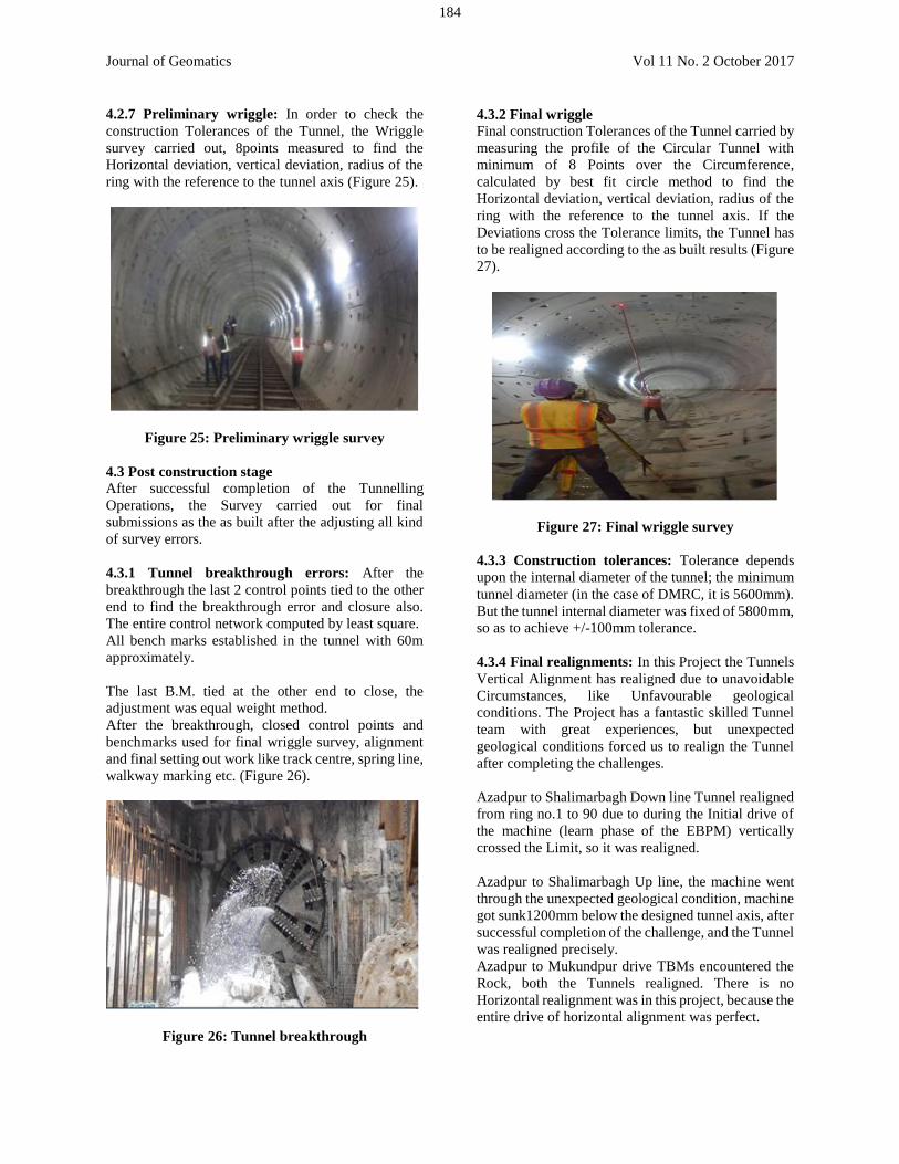
4.2.7 Preliminary wriggle: In order to check the
construction Tolerances of the Tunnel, the Wriggle
survey carried out, 8points measured to find the
Horizontal deviation, vertical deviation, radius of the
ring with the reference to the tunnel axis (Figure 25).
Figure 25: Preliminary wriggle survey
4.3 Post construction stage
After successful completion of the Tunnelling
Operations, the Survey carried out for final
submissions as the as built after the adjusting all kind
of survey errors.
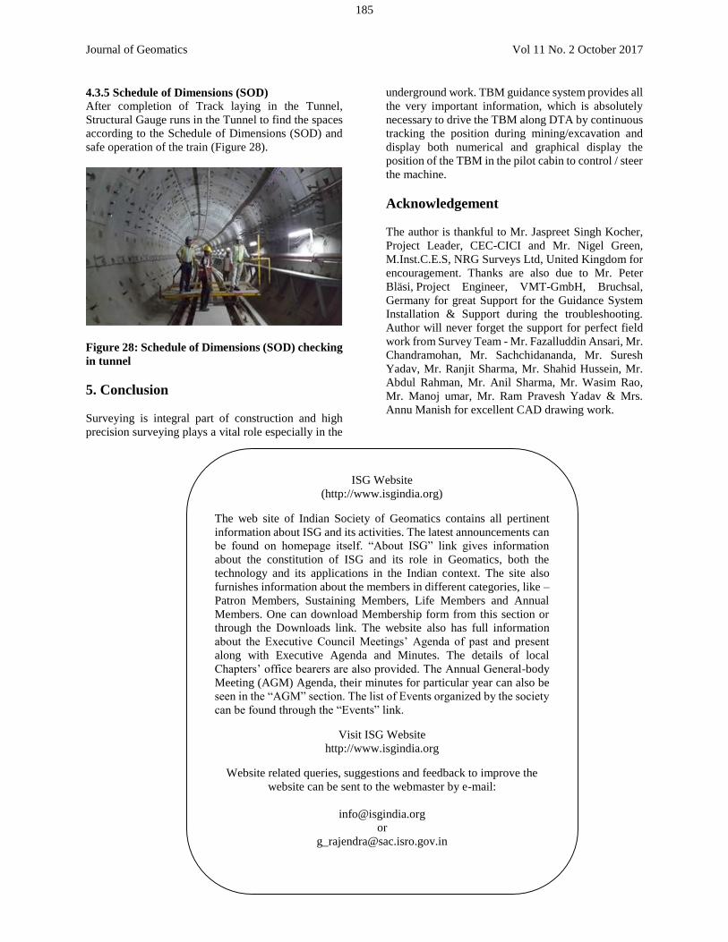
4.3.1 Tunnel breakthrough errors: After the
breakthrough the last 2 control points tied to the other
end to find the breakthrough error and closure also.
The entire control network computed by least square.
All bench marks established in the tunnel with 60m
approximately.
The last B.M. tied at the other end to close, the
adjustment was equal weight method.
After the breakthrough, closed control points and
benchmarks used for final wriggle survey, alignment
and final setting out work like track centre, spring line,
walkway marking etc. (Figure 26).
Figure 26: Tunnel breakthrough
4.3.2 Final wriggle
Final construction Tolerances of the Tunnel carried by
measuring the profile of the Circular Tunnel with
minimum of 8 Points over the Circumference,
calculated by best fit circle method to find the
Horizontal deviation, vertical deviation, radius of the
ring with the reference to the tunnel axis. If the
Deviations cross the Tolerance limits, the Tunnel has
to be realigned according to the as built results (Figure
27).
Figure 27: Final wriggle survey
4.3.3 Construction tolerances: Tolerance depends
upon the internal diameter of the tunnel; the minimum
tunnel diameter (in the case of DMRC, it is 5600mm).
But the tunnel internal diameter was fixed of 5800mm,
so as to achieve +/-100mm tolerance.
4.3.4 Final realignments: In this Project the Tunnels
Vertical Alignment has realigned due to unavoidable
Circumstances, like Unfavourable geological
conditions. The Project has a fantastic skilled Tunnel
team with great experiences, but unexpected
geological conditions forced us to realign the Tunnel
after completing the challenges.
Azadpur to Shalimarbagh Down line Tunnel realigned
from ring no.1 to 90 due to during the Initial drive of
the machine (learn phase of the EBPM) vertically
crossed the Limit, so it was realigned.
Azadpur to Shalimarbagh Up line, the machine went
through the unexpected geological condition, machine
got sunk1200mm below the designed tunnel axis, after
successful completion of the challenge, and the Tunnel
was realigned precisely.
Azadpur to Mukundpur drive TBMs encountered the
Rock, both the Tunnels realigned. There is no
Horizontal realignment was in this project, because the
entire drive of horizontal alignment was perfect.
184
Journal of Geomatics Vol 11 No. 2 October 2017
4.3.5 Schedule of Dimensions (SOD)
After completion of Track laying in the Tunnel,
Structural Gauge runs in the Tunnel to find the spaces
according to the Schedule of Dimensions (SOD) and
safe operation of the train (Figure 28).
Figure 28: Schedule of Dimensions (SOD) checking
in tunnel
5. Conclusion
Surveying is integral part of construction and high
precision surveying plays a vital role especially in the
underground work. TBM guidance system provides all
the very important information, which is absolutely
necessary to drive the TBM along DTA by continuous
tracking the position during mining/excavation and
display both numerical and graphical display the
position of the TBM in the pilot cabin to control / steer
the machine.
Acknowledgement
The author is thankful to Mr. Jaspreet Singh Kocher,
Project Leader, CEC-CICI and Mr. Nigel Green,
M.Inst.C.E.S, NRG Surveys Ltd, United Kingdom for
encouragement. Thanks are also due to Mr. Peter
Bläsi, Project Engineer, VMT-GmbH, Bruchsal,
Germany for great Support for the Guidance System
Installation & Support during the troubleshooting.
Author will never forget the support for perfect field
work from Survey Team - Mr. Fazalluddin Ansari, Mr.
Chandramohan, Mr. Sachchidananda, Mr. Suresh
Yadav, Mr. Ranjit Sharma, Mr. Shahid Hussein, Mr.
Abdul Rahman, Mr. Anil Sharma, Mr. Wasim Rao,
Mr. Manoj umar, Mr. Ram Pravesh Yadav & Mrs.
Annu Manish for excellent CAD drawing work.
ISG Website
(http://www.isgindia.org)
The web site of Indian Society of Geomatics contains all pertinent
information about ISG and its activities. The latest announcements can
be found on homepage itself. “About ISG” link gives information
about the constitution of ISG and its role in Geomatics, both the
technology and its applications in the Indian context. The site also
furnishes information about the members in different categories, like –
Patron Members, Sustaining Members, Life Members and Annual
Members. One can download Membership form from this section or
through the Downloads link. The website also has full information
about the Executive Council Meetings’ Agenda of past and present
along with Executive Agenda and Minutes. The details of local
Chapters’ office bearers are also provided. The Annual General-body
Meeting (AGM) Agenda, their minutes for particular year can also be
seen in the “AGM” section. The list of Events organized by the society
can be found through the “Events” link.
Visit ISG Website
http://www.isgindia.org
Website related queries, suggestions and feedback to improve the
website can be sent to the webmaster by e-mail:
or
or
185


![Fans for Metro Tunnel Design[1]](https://img.pdfslide.us/doc/110x75/5534c1834a7959824c8b4c6e/fans-for-metro-tunnel-design1.jpg)