Embed Size (px)
Citation preview

INTERNSHIP REPORT LOKESH C S
Dept. of Civil Engineering, K.V.G.C.E, Sullia, DK Page 1
CHAPTER 1
INTRODUCTION
1.1 ABOUT THE ORGANIZATION
Coastal Projects Limited (CPL) Established in the year 1995 and headquartered in
Hyderabad, leaving its foot prints and stepping forward in constructing the Nation’s
future, Coastal Projects Limited (CPL) is a well-established Construction company in
public sector, which has spread its wings in developing infrastructure all over the
country. Today, with its vast expertise, CPL has emerged as one of the pioneers and
specialists in the Underground Excavations covering all jobs of civil construction of
Tunnels for Underground Tubes and Underground Stations for Metro rails in difficult
Urban conditions; Underground Power House Complexes, Tunnels, Pump house and
Surge Pools for Hydro Power Projects in challenging geological conditions.
CPL is endowed with very efficient work force for tunnel construction in Irrigation
Projects and Railway Tunnels in arduous geological and geotechnical conditions of North
East sector. The Company’s success is driven by more than building some of the most
advanced facilities for its Clients. CPL is well known for its distinctive ability to
implement innovative project management techniques and to serve as a reliable provider
of knowledge-driven solutions for their complex construction projects. The Company has
complete and well equipped technical backup and suitably trained and specialized man
power in their respective fields and has been able to make commendable strides in its
chosen field of infrastructure.
The Company has executed contracts of well-established Corporations both in Private
and Public Sector and is well versed with the dynamics of project execution. With the
experience gained in the field of underground tunnelling, it has entered into joint ventures
with some of the leading companies and firms to take up prestigious Bangalore
Underground Metro Rail Projects, mega projects in power generation and irrigation to
expand its horizons

INTERNSHIP REPORT LOKESH C S
Dept. of Civil Engineering, K.V.G.C.E, Sullia, DK Page 2
1.2 VISION OF THE ORGANIZATION
CPL team of construction professionals offers a single- source solution for all the
underground construction related needs. Efficient leaders, supported by experienced and
well trained technical staff which includes among others, Engineering personnel viz.
designers, planners, technicians and tradesmen, who are adept in handling the latest
equipment that facilitate in increasing productivity in underground tunnelling works, can
adopt themselves easily to the new technologies to achieve national and international
work standards.
1.3 MISSION OF THE ORGANIZATION
The missions of the organization are as follows:
Achieve work life balance in a challenging and rewarding environment
Deliver value with integrity and transparency.
Providing a conductive environment for employees to not just perform but to
consistently out-perform themselves by working on challenging projects.
To encourage the employees to stay abreast of the latest technologies and
continuously train them on latest technologies.
1.4 CORE VALUES OF THE ORGANIZATION
Coastal Projects Limited, make every moment of working career an unforgettable
experience
Coastal Projects has some core values
a. Quality They are driven to attend to clients concerns responsively towards
delivering commitments.
b. Innovative and creative: CPL is well known for its distinctive ability to
implement innovative project management techniques and to serve as a reliable
provider of knowledge-driven solutions for their complex construction projects.

INTERNSHIP REPORT LOKESH C S
Dept. of Civil Engineering, K.V.G.C.E, Sullia, DK Page 3
c. Client values: The Company’s success is driven by more than building some of
the most advanced facilities for its Clients.
d. Employees: The Company pursues business opportunities that will enable them
to be competitive by empowering employees to take on initiative and at the same
time promote ownership of responsibilities and accountabilities to results and
performance.
1.5 QUALITY ASSURANCE OF THE ORGANIZATION
1.5.1 Quality Policy
Coastal Project Limited is committed to enhance customer satisfaction by customer
compliance to customer technical standards, reliability of services, adherence to time
schedule at competitive price through continual improvement and effective
implementation of Quality Management System. Coastal is also committed to provide
competitive and creative environment to its employees to achieve future goals of the
company.
1.5.2 Quality Objectives
The following are the quality objectives of GYT COASTAL-JV
The primary quality objective is to complete the project in accordance with
BMRCL requirements, within schedule, within budget and in conformance with
the Quality Assurance Manual and other required standards.
To successfully execute projects undertaken.
To describe the operational arrangements, resources and sequence/interaction
activities, which the JV will implement in order to provide adequate confidence of
meeting the contractual requirements for quality to the client BMRCL.
1.5.3 Quality Management System
To establish and maintain documentation quality system in orderly and understandable
manner and consistence with the requirements of ISO 9001:1994.Each basic element of

INTERNSHIP REPORT LOKESH C S
Dept. of Civil Engineering, K.V.G.C.E, Sullia, DK Page 4
the quality system program, as defined in this project quality management plan, shall be
applied to all activities performed by GYT-Coastal JV and its sub-contractors/vendors.
1.6 ORGANIZATION AND MANAGEMENT
In every organization, the most important asset is the people that play essential role in the
performance of the company’s functions and responsibilities. Thus CPL has emerged as
one of the pioneers and specialists in the Underground Excavations covering all jobs of
civil construction of Tunnels for Underground Tubes and Underground Stations for
Metro rails in difficult urban conditions. The Bangalore Metro Rail Project has been
projected as one that will benefit everybody by its reduction in congestion, pollution and
increased mobility. CPL team of construction professionals offers a single- source
solution for all the underground construction related needs. The company has
organization and the employees, because of the mutual benefits that simultaneously being
enjoyed by, has grown tremendously and would like to be on the level where they should
be. Having confidence in the organization, they aim high.
1.7 PROJECT OVERVIEW
The Bangalore Metro Rail Project was proposed in 2002 and a special purpose vehicle,
the Bangalore Metro Rail Transit Limited (BMRTL) was formed to implement the Metro
Rail Project.
1.7.1 Majestic Metro Station
Bangalore (also Bengaluru) in the south west of India is the country's fastest-growing
metropolitan area. It seems to set to confirm a place as the third-largest city with a
population of well over five million and with more in surrounding satellite communities.
The state capital of Karnataka, Bangalore is a leading research Centre with a
concentration of the international information technology industry. An important location
for Indian Railways, Bangalore's urban transport has been made up of taxis, buses and
lightweight powered rickshaws. Coupled with the need to sustain the city's growth, the
social and economic transformation has focused official attention on developing rapid

INTERNSHIP REPORT LOKESH C S
Dept. of Civil Engineering, K.V.G.C.E, Sullia, DK Page 5
high-volume rail-based public transport. Fig 1.1, 1.2 and 1.3 shows the logo, master plan of
Construction Contract of Underground Majestic Station (Interchange Station) for
Bangalore metro Rail Project Phase-1Bengaluru and Schematic route map for Majestic
metro respectively.
Fig 1.1 Logo of GYT Coastal JV
Guangdong Yuantian Engineering Company Limited (referred as GYT) is a first level
construction contractor of national water conservancy and hydropower engineering, a
subsidiary company of Guangdong construction engineering group corporation Ltd. GYT
was established in 2001. GYT has 7 first class national qualification and 5 second class
national qualification and has been awarded “Credit Enterprise of Guangdong Province”
for 18 years.
The interchange station at Majestic is an underground station where the two underground
segments of Purple and Green lines intersect each other approximately at 90°.The station
is designed around island platform configuration of 10m width each. The two platforms
are separated by a mezzanine in between to facilitate the interchange of passengers from
upper platform to lower platform and vice versa within the paid area without having to
cross the ticket gates. Through the entry structure at ground level, the passengers proceed
to the paid area of the concourse after passing through the gates.
From this level the passengers can go directly to the upper and lower platforms directly.
The ticket vending facilities are located at this level in the unpaid area. Over the station
box, office accommodation in eight storied structures have been planned with its
longitudinal axis parallel to the N-S direction, to facilitate natural lighting into the station
at upper platform level and mezzanine level. The station layout and the tunnels carrying

INTERNSHIP REPORT LOKESH C S
Dept. of Civil Engineering, K.V.G.C.E, Sullia, DK Page 6
the tracks between the stations have governed the rail levels, which are 8mts for the
Purple Line and 20mts for the Green Line.
1.7.2 Station Construction
In Detailed works Program revision, have made a Grid wise plan of 20-25 m length and
have planned to progress from Zone E centre to all other directions of Zone A ,B,D and
for Zone C the works is planned to progress from East Contract boundary toward Zone E.
The schematic bifurcation of the Grid wise plan as an extract of the DWP for all Zones
with the completion dates of the activities have been mentioned for ready reference &
understanding.
The Purple Line of the Namma Metro is part of the metro rail system for the city
of Bangalore, India. The 18.22 km line connects Baiyyappanahalli to Mysore Road. The
line links the eastern, central and western areas of Bangalore. The Purple Line is mostly
elevated, with 12 elevated stations and 4 underground stations. The Majestic station
serves as the interchange station with the Green Line. It generally takes around 35
minutes to travel from one end to another end, as compared to around 90 minutes taken to
travel on road. There are 17 stations on the Purple Line. All underground stations were
built using the cut-and-cover method. Most underground stations are 300 meters long and
25 meters wide. The interchange station at Majestic is much larger.
The Green Line of the Namma Metro is part of the mass-transit rail system for the city
of Bangalore, India. It will consist of 25 stations from Nagasandra to Puttenahalli under
Phase I. When Phase II is completed, it will stretch from BIEC in the north to Anjanapura
in the south. The line will measure 24.20 km and will be mostly elevated, with some
stations underground. However, the stretch between Sampige Road to Kempegowda will
be opened to the public by August 2016. The southern stretch of the line will however be
operational by December 2016, thereby completing the entire Phase I project. There are
32 stations on the Green Line. 13 stations, from Nagasandra to Sampige Road are shown
in above.

INTERNSHIP REPORT LOKESH C S
Dept. of Civil Engineering, K.V.G.C.E, Sullia, DK Page 7
Fig 1.2 The Schematic Bifurcation of The Grid Wise Plan

INTERNSHIP REPORT LOKESH C S
Dept. of Civil Engineering, K.V.G.C.E, Sullia, DK Page 8
Fig 1.3 Schematic route map for Majestic metro
1.7.3 Project partners of GYT Coastal-JV
The Company’s success is driven by more than building some of the most advanced
facilities for its Clients.
Client: Bangalore Metro Rail Corporation Ltd. (BMRCL). A joint venture of
government of Karnataka and government of India.
Contractors: Guangdong Yuantian Engineering co (GYT) & Coastal projects Ltd (CPL)
joint venture (JV).
General consultant: RITES-OC-PBI-SYSTRA
Detailed design consultant: Mott Mac Donald
1.7.4 Master plan of Underground Majestic Station (Interchange
Station)
Site Adress: Kempegowda Bus Station (KSRTC), Bengaluru

INTERNSHIP REPORT LOKESH C S
Dept. of Civil Engineering, K.V.G.C.E, Sullia, DK Page 9
Fig 1.4 shows Master plan of Underground Majestic Station (Interchange Station).
Fig 1.4 Master plan of Underground Majestic Station (Interchange Station)
1.7.5 Site location map of Underground Majestic Station (Interchange
Station), Bengaluru
Fig 1.5 shows Site location map of Underground Majestic Station.
Fig 1.5 Site location map of Underground Majestic Station

INTERNSHIP REPORT LOKESH C S
Dept. of Civil Engineering, K.V.G.C.E, Sullia, DK Page 10
1.7.6 Project Information of of Underground Majestic Station
(Interchange Station)
GYT-COASTAL JV:-The two parties have agreed to appoint GYT as lead partner of the
JOINT VENTURE for the performance of the contract and COASTAL as member
partner. The site layout is well planned with access to all the areas in the site and thus it
enhances the productivity. Steel yards are planned in such a way that minimum lead
distance is required.
Majestic station is the largest metro station in India. It has three levels with a total
surface area of 48,000 square metres (520,000 sq ft).
The station platform is 365 metres long for the Purple Line, and 300 metres long
for the Green Line.
The station's platforms are designed to handle 20,000 commuters at any given
time.
The upper level houses the ticket counters, the at-grade level is utilized by Purple
Line trains, and the underground level is utilized by Green Line trains.
The station has 12 staircases, 24 escalators, 18 emergency exits and 8 toilets.
The site is well secured with the following facilities.
Site is well secured with temporary compound wall from all sides.
Area is secured by Security guards and CCTV cameras.
Every vehicle and person entering site is recorded at the entrance.
The steel yard and scrap yard are constantly watched by a security.
Temporary facilities provided at the site.
Labor camps are inside site in order to save the transportation cost and time.
Site is well illuminated in the night.
Drinking water and toilets for labor is provided at the site.
Temporary access roads are provided to the site.
Transportation and accommodation facility is given to the workers.
INTERNSHIP REPORT LOKESH C S
Dept. of Civil Engineering, K.V.G.C.E, Sullia, DK Page 11
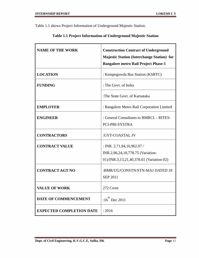
Table 1.1 shows Project Information of Underground Majestic Station.
Table 1.1 Project Information of Underground Majestic Station
NAME OF THE WORK Construction Contract of Underground
Majestic Station (Interchange Station) for
Bangalore metro Rail Project Phase-1
LOCATION : Kempegowda Bus Station (KSRTC)
FUNDING : The Govt. of India
:The State Govt. of Karnataka
EMPLOYER : Bangalore Metro Rail Corporation Limited
ENGINEER : General Consultants to BMRCL - RITES-
PCI-PBI-SYSTRA
CONTRACTORS :GYT-COASTAL JV
CONTRACT VALUE : INR. 2,71,94,16,962.07 /
INR.2,96,24,18,778.75 (Variation-
01)/INR.3,13,21,40,378.61 (Variation-02)
CONTRACT AGT NO :BMR/UG/CONSTN/STN-MAJ DATED 18
SEP 2011
VALUE OF WORK 272 Crore
DATE OF COMMENCEMENT :16th
Dec 2011
EXPECTED COMPLETION DATE : 2016

INTERNSHIP REPORT LOKESH C S
Dept. of Civil Engineering, K.V.G.C.E, Sullia, DK Page 12
1.7.7 Site layout of Underground Majestic Station (Interchange Station)
Fig 1.6 shows Site layout of Underground Majestic Station (Interchange Station).
Fig 1.6 Site layout of Underground Majestic Station (Interchange Station)
INTERNSHIP REPORT LOKESH C S
Dept. of Civil Engineering, K.V.G.C.E, Sullia, DK Page 13
CHAPTER 2
ABOUT THE DEPARTMENT
2.1 SECTION OF THE COMPANY
The GYT-Coastal JV will ensure that all staff understand the importance of quality in
their work and accept the need to employ the working practices and procedures as
defined in the quality manual and the process procedure manual. All the working drawings
like structural drawing, sanitary drawing and electrical drawing are provided to the
respective sub-contractors based on the agreement (after the architectural drawing is selected
by the company) and then the project cost (bill of quantity) is calculated. Quality of the
organization is to describe the operational arrangements, resources and
sequence/interaction activities, which the JV will implement in order to provide
adequate confidence of meeting the contractual requirements for quality to the client
BMRCL. Fig 2.1 shows Organization Chart.
2.2 ROLES AND RESPONSIBILITIES
2.2.1 Management Representative
To ensure that the processes for quality management system are established,
implemented and maintained.
Conduct internal quality audits to assess the system performance and report it to
the top management.
Ensure awareness of customer requirements throughout the organization.
2.2.2 Roles of QA/QC Manager
The Quality Assurance Manager shall report to the Management Board.
Prepare, obtain approval, issue & implement quality assurance plan in compliance
with contract specifications & company requirements.
Be responsible for the interaction with the client, agencies, subcontractors and
internal departments on quality related matters.

INTERNSHIP REPORT LOKESH C S
Dept. of Civil Engineering, K.V.G.C.E, Sullia, DK Page 14
INTERNSHIP REPORT LOKESH C S
Dept. of Civil Engineering, K.V.G.C.E, Sullia, DK Page 15
Reports to the management as required.
Responsible for quality program implementation.
Carrying out inspection of outgoing construction activities at site.
Reports non-compliance and proposes remedial action to site staff and senior
management.
Responsible for conducting internal audit & report to management board.
Responsible for organizing third party external audits.
2.2.3 Roles of QA/QC Assistant Manager/Engineer
Report to the QA/QC Manager.
Responsible for material selection and mix combination to meet the specification
requirements within overall cost provisions.
Identifies all material requirements, sources.
Conducts qualification tests for source approval.
Conducts tests on materials.
Indents all laboratory equipment, commissions and conducts calibration exercises
as per plans.
Documents all tests in standard formats.
Conducts laboratory activities independently and reports any potential problems
to the higher authorities.
Follows up through remedial measures.
2.3 PLANT AND MACHINERY DEPARTMENT
Roles of Plant and Machinery in charge
• Report to Project Manager functionally.
• Co-ordinates with the Deputy Project Manager & Planning Engineer for daily
deployment of plant to various sections
• Conducts all preventive maintenance as per equipment manuals.

INTERNSHIP REPORT LOKESH C S
Dept. of Civil Engineering, K.V.G.C.E, Sullia, DK Page 16
• Ensures adequate stock fast moving spares.
• Allots duty roaster to operators.
• Administrates fuel oil supply, reconciles usage in consultation with Stores
Department and submits reconciliation statements at the end of each month to
Billing and Planning Section.
• Conducts repairs, breakdown maintenance, arranges alternative equipment’s when
required economically.
2.3.1 Batching plant
Batching Plant is a device that combines various ingredients to form concrete. Some of
these inputs include sand, water, aggregates, fly ash, admixtures and cement. A Batching
Plant can have a variety of parts and accessories, including: mixers, cement batchers,
aggregate batchers, conveyors, radial stackers, aggregate bins, cement bins, heaters,
chillers, cement silos, batch plant controls and dust collectors. Fig 2.1 shows Batching
plant at the site
Fig 2.2 Batching plant at the site

INTERNSHIP REPORT LOKESH C S
Dept. of Civil Engineering, K.V.G.C.E, Sullia, DK Page 17
Table 2.2 shows Total Machineries available at the site.
Table 2.2 Total Machineries available at the site
SI.
No Machinery Model/make
Total
Required
Available
at site
Balance
No’s
Required
1 Excavator/Rock breaker PC 300 4 4 0
2 Excavator PC 200 3 3 0
3 Long Stick & boom 19 m
2 2 0
4 Long Stick & boom 22 m
2 2 0
5 Dumper (10 cum cap)
6 6 0
6 Tractor Compressor for
Drilling/Blasting 3 3 0
7 Crawler 85 T cap Crane
1 1 0
8 Loader 3 Cum 1 1 0
9 Tower Crane fixed 2.9 Ton tip load - 55
mtr boom length 1 1 0
10 Tower Crane movable 2.9 Ton tip load - 55
mtr boom length 1 1 0
11 Batching Plant (60 cum/hr) 1 1 0
12 Batching Plant (Stand by) (30 cum/hr) 1 1 0
13 Concrete Boom Placer 35 Mtr length boom 1 1 0
14 Concrete Pump Stationery 30 Cum/Hr 1 1 0
15 Transit Mixer 7 Cum 6 6 0
16 Crawler Crane 100 T cap 1 1 0
17 Mobile Crane 80 T Cap 1 1 0
18 Mobile Crane 60 T Cap 1 1 0
19 Walk Behind roller 4T Cap 1 1 0
20 Plate Compactors
(Vibratory Hammer) 6 2 4
21 Concrete Bucket (Banana 1 cum 1 1 0

INTERNSHIP REPORT LOKESH C S
Dept. of Civil Engineering, K.V.G.C.E, Sullia, DK Page 18
Bucket)
22 Compressor 400 cfm 1 1 0
23 Bar Cutting Machine
5 5 0
24 Bar Bending Machine
5 5 0
2.4 QUALITY DEPARTMENT IN THE COMPANY
To ensure the construction process of the works, which directly affect the quality, will be
executed under planned and controlled condition. The project manager is overall
responsible for implementation and supervising the construction work process. The
station manager will be responsible for all the construction activities at the site. The job
will be executing by a well experienced sub-contracting agency, the site engineer and
foreman of GYTC will directly supervise the work at the site and will be responsible for
controlling the day to day progress. The QC in charge is responsible for controlling the
inspection and testing activities.
2.4.1 Quality Implementation at Site
The maintenance of the quality of the work is the main objective of the company. The
company quality management system performs various activities to maintain the quality
of the work and materials. The quality manager ensures the quality of the site works and
respective materials that are procured at the site.
The GYT-Coastal JV will ensure that all staff understand the importance of quality in
their work and accept the need to employ the working practices and procedures as
defined in the quality manual and the process procedure manual.

INTERNSHIP REPORT LOKESH C S
Dept. of Civil Engineering, K.V.G.C.E, Sullia, DK Page 19
2.4.2 Quality system structure and documentation
Figure 2.2 shows Documentation Structure at Site.
Fig 2.3 Documentation Structure at Site
2.5 QUALITY CONTROL TESTS CONDUCTED AT SITE
The quality management team ensures the verification of various materials purchased
from vendors by conducting respective tests according to the standard specification. The
various tests conducted in the site are as follows.
2.5.1 Consistency
To determine the quantity of water required to produce a cement paste of standard
Consistency.
The standard consistency of a cement paste is defined as that consistency which
will permit the vicat plunger to penetrate to a point 5 to 7 mm from the bottom of
the vicat mould.
For finding out initial setting time, final setting time, soundness of cement and
compressive strength of cement, it is necessary to fix the quantity of water to be
mixed in cement in each case. Requirements as per IS 269: 2015 Clause 7 (Table-
3) for OPC 53 Grade.

INTERNSHIP REPORT LOKESH C S
Dept. of Civil Engineering, K.V.G.C.E, Sullia, DK Page 20
Result got when test conducted at the site is 27.4%
2.5.2 Slump Test
Slump test is the most widely used test in the field and laboratory which is used to check
the consistency of concrete used at a construction site. It provides useful information on
the uniformity in the day to day or even hour to hour production of concrete. The main
apparatus used for this test was 30cm height, 20cm bottom width and 10cm top width
cylindrical cone, 60cm tamping rod and iron plate. The workability depends on the
reversed gap between the cone and the fresh concrete after tamping and removing of the
cone.
The workability is classified as:
Very low when the height is 0 – 25mm
Low when the height is 25 – 50mm
Medium when the height is 50 – 100mm
The test result obtained for water cement ratio 0.5 is 80mm.
2.5.3 Compressive Strength Test
The purpose of the test is to determine the compressive strength of the concrete.
Procedure
Place the specimen in the machine and slowly bring the blocks to bear on the
specimen without shock until failure occurs.
Operate the machine at a constant rate within the range of 0.140 to 0.350 Mpa per
second.
Table 2.3 Compressive strength test results conducted at site
Sl
No.
Area of cube
(mm2)
Cube Testing
period (days)
Compressive strength (Mpa)
(Avg. of three results)
1 150 x 150 3 34
2 150 x 150 7 42.5
3 150 x 150 28 57

INTERNSHIP REPORT LOKESH C S
Dept. of Civil Engineering, K.V.G.C.E, Sullia, DK Page 21
Fig 2.3 shows Compression Test Machine and Table 2.3 Compressive strength test results
conducted at site.
Fig 2.4 Compression test
2.5.4 Final test report on physical properties of cement
Fig 2.4 shows Final test report on physical properties of cement
Fig 2.5 Final test report on physical properties of cement

INTERNSHIP REPORT LOKESH C S
Dept. of Civil Engineering, K.V.G.C.E, Sullia, DK Page 22
2.6 STORE & PURCHASE DEPARTMENT
Procedure followed by GYT-Coastal Projects Ltd
1. Preparation of requirement indent (purchase requisition)
Firstly a list of required items is listed out and then it shall be submitted to the indenter,
department heads and managers accordingly as shown in Fig.2.5 (which explains the
purchase requisition form used at the site). Then company will verify the same and sign
the purchase requisition.
Fig 2.6: Purchase requisition form that was used at the site
2. Quotation from seller (dealers)
The purchase requisition is then allowed to share with various sellers and accordingly
quotations are to be collected from them.
3. Selection of the best & lowest quotation
Quotation from various dealers is to be referred and out of which the best and economical
quotation is approved by the manager.
4. Quality assurance by the seller (dealer)
Here the seller checks the requirement accordingly and assures that he shall assure that he
shall provide the items of best quality as per the quotation.

INTERNSHIP REPORT LOKESH C S
Dept. of Civil Engineering, K.V.G.C.E, Sullia, DK Page 23
5. Material issue challan & Register
After all the items are been received from the seller use of items on site a material issue
challan is to filled which shall be signed by approver, receiver & store keeper hence
accordingly the items are issued and brought into work. Different registers are maintained
with respect to its returnable policy i.e. diesel, survey instruments, tools etc. Fig 2.6
shows Material issue challan that was used at the site.
Fig 2.7 Material issue challan that was used at the site
2.7 SAFETY DEPARTMENT
Human life is irreplaceable, which is susceptible of minor infections. Nowadays it has
become common to hear accidents on the construction industry. The more the accidents
are becoming redundant the responsibility of the contractors and the attention to give to
safety of the workers is progressing to be paramount. Therefore, it cannot be denied to
work on increasing the safety condition of the site. The most effective way of avoiding
risks is the preventive strategy. As the health professionals use to say “prevention is
better than cure”, it is more than reasonable to be abide by such motto. Less concerned
safety rule, regulation and training are among the problem in the site.

INTERNSHIP REPORT LOKESH C S
Dept. of Civil Engineering, K.V.G.C.E, Sullia, DK Page 24
Safety of all working staffs and visitors should be observed to a highest care. Infliction of
injury shall be minimized. For this prior readiness is very important. The safety
management will be carried out with a special superintendent to be assigned on site. The
superintendent will be assisted with a dresser to be employed for the site.
2.7.1 Health, Safety and Environmental Policy
Coastal Project Limited is committed is poised to achieve excellence in adoption of well-
established quality management system by a perpetual pursuit for perfection. Health and
safety of the work force employed, coupled with environmental protection is the foremost
priority of the company in the accomplishment of its goals and objectives.
2.7.2 Daily site safety inspection
Both the work site and safety supervisors are to conduct daily site safety inspection
around work activities and premises to ensure that work methods and the sites are
maintained to an acceptable standard.
2.7.3 Accident and Incident Investigation
GYT-COASTAL JV shall undertake detailed investigations into all accidents and
incidents including near misses to establish causes and prevent recurrence. A member of
the site Health and Safety Management team shall carry out such investigations that shall
identify the immediate and underlying causes. An investigation report shall be prepared
detailing remedial actions and sent to the client. GYT-COASTAL JV shall ensure that
health and safety information and statistics are communicated to client.
The four types of safety measures undertaken at sites, namely,
Personal Safety – here labours are educated about accidents that occur at work
environment and about the safety guards to be worn for a particular work and reduce the
risks.
Equipment Safety – Proper check, care and maintenance of any equipment used at the
site is taken up.

INTERNSHIP REPORT LOKESH C S
Dept. of Civil Engineering, K.V.G.C.E, Sullia, DK Page 25
Environmental Safety – The working condition at the site to be healthy and pollution of
the site should be prevented using proper control measures.
Material Safety – only required amount of material for a particular work is permitted at
the site and wastage of the material is avoided.
Fig 2.8: Safety helmets
2.7.4 Safety Precautions at Site
The work should start daily at 8:00 hours
Child labour is strictly prohibited, Contractor should not be deploy under age
labours for work(under 18 years of age)
Children are not allowed in any construction area
PPEs should be worn by workers, supervisor and engineers.
Safe work procedures shall be strictly followed.
No work shall be carried out without the supervision of competent person
All accidents/incidents are to be reported safety department immediately.
Safety officers’ helmet Sub contractors’ helmet
Contractor’s helmet Client’s helmet
INTERNSHIP REPORT LOKESH C S
Dept. of Civil Engineering, K.V.G.C.E, Sullia, DK Page 26
All electrically operated machines/ equipment's must be properly earthed.
Electrical repairs should be carried out by a qualified and authorized electrician.
Only trained and license holder operators are allowed to drive the vehicle and
equipment
Proper usage of tools and tackles during lifting operation at the site.
Spark / flame arrestor is to be fitted on gas cutting/welding equipment's.
Domestic LPG cylinders should not be used. Only industrial gas cylinders are
allowed at the site.
Work place should be maintained with good housekeeping and area should be
kept neat.
Uses of alcohol, drugs and smoking are strictly prohibited in the site.
Each day inspection was being done to check the safety working environment of
the site.
Lift and other openings were covered properly with reinforcement bars.
The contractors shall make in every work site, effective arrangements to provide
sufficient supply of drinking water with minimum quantity of 5 liters per
workman per day. Quantity of the drinking water shall confirm to the
requirements of national standards on public health,
Special instructions are given to the workers then and there. Example, if a person
is lifting a material, the entire load must be on the knees and legs and not on the
spinal cord.
The different permits required are
Height work permit
Confined space entry
Line breaking permit
Mobile crane operation permit
Each delivery of the material shall be visually inspected when delivered on the
site. The delivered materials shall be clean, homogeneous and free from debris,
root plant, and any other deleterious matter.
All contractors and sub-contractors employees shall comply with requirements of
the approved Health and Safety plan.

INTERNSHIP REPORT LOKESH C S
Dept. of Civil Engineering, K.V.G.C.E, Sullia, DK Page 27
Workers shall carefully operate the hand tools, machines and all other
equipment’s and safety belt/safety harness shall be used by the workers, wherever
necessary.
Health and safety of the work force employed, coupled with environmental protection is
the foremost priority of the company in the accomplishment of its goals and objectives.
Fig 2.8 (a) and (b) shows safety precaution and sign board
Fig 2.9 (a) sign board Fig 2.9 (b) safety precaution

INTERNSHIP REPORT LOKESH C S
Dept. of Civil Engineering, K.V.G.C.E, Sullia, DK Page 28
CHAPTER 3
TASKS PERFORMED
3.1 GENERAL
The internship training program at the site was controlling how the work is going on and
supervising the work based on the given check list which was given from the office. The
checklist for site supervisors is issued in order to ensure a uniform system of supervision
of building construction projects and as a result ensure the quality of construction. In the
checklist the responsibilities, liabilities and limitations of the supervisor are briefly
mentioned in the steps to the general terms.
Details of construction are specified in the drawings, technical specifications and in the
general and special conditions of the contract. The duty of site engineer was to ensure
that the construction works are executed in accordance with the contract requirement. In
the application of the checklist the details specified in the contract document always
precede before the application and use of it. There are also tables and forms in the
checklist that help as records of the incidences affecting the work and as references. In
addition the standard technical specification was used as reference on the preparation of
the checklist and shall always have precedence over the checklist. Therefore, most of the
internship program work was spent at site to become more familiar with site works and to
get more practical knowledge. Site work in general includes every kind of work executed
at the site starting from setting out till finishing works based on the given specification
and methodology. The site work that was observed in the four month internship period
was in the sub structure work and super structure work exclusively.
Any structure below the ground floor slab level including the basement, retaining walls,
ground slab, plinth beam and foundation is called a substructure. In most of the cases,
substructure work can be categorized as earthwork, concrete work and masonry work.
In the training program was about the various inspection works like reinforcement
checks, alignment checks and shuttering checks that has to be done before giving

INTERNSHIP REPORT LOKESH C S
Dept. of Civil Engineering, K.V.G.C.E, Sullia, DK Page 29
clearance for concreting and the finishing works including mechanical, electrical and
plumbing (MEP) fittings. During this internship program it was possible to study about
the practical difficulties in working with conventional shuttering, manual concreting and
various machineries that is being used in the site. The entire internship program of four
months included study of both structural as well as finishing works. The structural works
included reinforcement, shuttering and concreting of footings, columns, beams and slabs
and also block work. The finishing works included plastering, fitting of electrical and
plumbing accessories. Any new staff joining the project shall attend SHE safety induction
training organized by GYTCOASTAL JV SHE officers/ Engineers in which all major
applicable SHE Rules and Regulations shall be highlighted. An attendance list of this
training will be filed in the safety department with the signature of each employee who
has attended the training programme. Fig 3.1 shows N-S platform level part plan block
work drawing
Fig 3.1: N-S platform level part plan block work drawing
3.2 VARIOUS TASKS PERFORMED AT THE SITE
3.2.1 Concrete Form Work
As fresh concrete is in plastic state when it is placed for construction purpose so, it
becomes necessary to provide some temporary structure to confine and support the
concrete till it gains sufficient strength for self-supporting. This temporary structure is
INTERNSHIP REPORT LOKESH C S
Dept. of Civil Engineering, K.V.G.C.E, Sullia, DK Page 30
called form work. Concrete formwork serves as a mould to produce concrete elements
having a desired size and configuration. It is usually erected for this purpose and then
removed after the concrete has cured to a satisfactory strength. In some cases, concrete
forms may be left in place to become part of the permanent structure. For satisfactory
performance, formwork must be adequately strong and stiff to carry the loads produced
by the concrete, the workers placing and finishing the concrete, and any equipment or
materials supported by the forms. In the site the form work material used was plywood
material which has a good surface finish.
Plywood is used extensively for concrete forms and provides the following advantages:
It is economical in large panels.
It is available in various thicknesses.
It creates smooth, finished surfaces on concrete.
The general step used to construct a formwork in the site is:
Prepare the false works in the desired position and level.
Preparing the form work in a desired shape based on the drawing or the size of the
structure that is going to be cast.
Painting with a releasing agent if needed.
Nailing it with appropriate bracing element and false work.
One side of the wall formwork is first assembled ensuring that it is correctly aligned,
plumbed and strutted.
The steel reinforcement cage is then placed and positioned before the other side of the
formwork is erected and fixed.
Plywood sheet in combination with timber is the most common material used for wall
formwork.
To be rigid enough to confine plastic concrete at the lines grades and dimensions
indicated on the form plans without bulging or sagging under the load.
To be constructed as mortar tight as possible to prevent the loss of concrete
ingredients throughout the joints between the sections, and
To be easy to remove with minimal damage to the concrete surface.

INTERNSHIP REPORT LOKESH C S
Dept. of Civil Engineering, K.V.G.C.E, Sullia, DK Page 31
Fig 3.2 (a) and (b) shows Form work carried out at the site.
(a) (b)
Fig 3.2 Form work carried out at the site
3.2.2 Reinforcement
Concrete is much weaker in tension than in compression. Its tensile strength is
approximately 10% of its compressive strength. Therefore, concrete is generally used in
conjunction with steel reinforcement, which provides the tensile strength in a concrete
member. The use of plain concrete without steel reinforcement is limited to pavements
and some slabs-on-ground. Steel is the ideal material to complement concrete because the
thermal expansion of both materials is the same. In other words, when heated or cooled,
both steel and concrete expand or contract equally and no stresses will be developed.
Fig 3.3 Reinforcement work for PCC

INTERNSHIP REPORT LOKESH C S
Dept. of Civil Engineering, K.V.G.C.E, Sullia, DK Page 32
Steel also bonds well with concrete. In a composite material, the bond between two
materials is necessary for it to function as a single material. The bond between steel
and concrete is due to the chemistry of the two materials, which produces a chemical
bond between them. Additionally, as water from concrete evaporates, it shrinks and
grips the steel bars, making a mechanical bond. The mechanical bond is enhanced by
using reinforcing bars, or rebar, that have surface deformations. Because a mechanical
bond is a function of the area a contact between the two materials, surface
deformations increase that area, thereby increasing the bond. For the same reason,
rebar that have a light, firm layer of rut bonds better with concrete. Rust that is
produced by leaving rebar outdoors on a construction site for a few days or weeks is
not objectionable as long as the rust is not loose or flaky. Loose and flaky crust should
be scraped using burlap or a piece of cloth. Excessively rusted rebar should not be
used. Reinforcement grade of Fe 500 is extensively used in the project. Bars in the
range of 8mm to 32mm were used in the projects. Fig 3.3 and Fig 3.4 Reinforcement
work for PCC and Reinforcement work for the SVS shaft.
Fig 3.4 Reinforcement work for the SVS shaft
Before bulk purchase and transporting to the site they conduct tensile strength test from
the store, by taking sample from a place where they are intending to supply the material.
Such sampling will involve the consulting office and the result will be communicated.
When they receive approval, as it fulfils the expected minimum tensile strength, they
proceed to purchase the same. Place of deposit was made ready before its arrival on site

INTERNSHIP REPORT LOKESH C S
Dept. of Civil Engineering, K.V.G.C.E, Sullia, DK Page 33
where it should be damped. A platform elevated from the top surface of the soil, that
would ensure the avoidance of minimum contact were prepared. Then placed there, and
was protected from any detrimental moisture, grease or oil or other substances that may
affect its quality. Shop drawing or bar schedule was produced by the Office Engineer, in
accordance to the structural design. This shop drawing or bar schedule was submitted to
the Resident Engineer and upon his approval mass production will be induced.
Bar bending workshop were situated in a place where it could be close to the site where
the bar is going to be placed in position. The bending of all types of reinforcement bars
was take place within the workshop. Except the column reinforcement bars all was tied
and placed in position exactly in a position where they are intended to be situated. Fig 3.5
(a) and (b) shows Storage of steel at the site
(a) (b)
Fig 3.5 Storage of steel at the site
On the sub-structure work hauling was performed by labour. But on the super structure it
is through the help of the mobile crane, that the required amount and type of
reinforcement bar will be conveyed. After placing in position of the reinforcement bar
and before the concrete pouring any dust particle was removed or cleaned. On horizontal
structures like the reinforced concrete in order to maintain the allowable concrete cover
depth or thickness concrete spacers was produced and cured and placed in position.

INTERNSHIP REPORT LOKESH C S
Dept. of Civil Engineering, K.V.G.C.E, Sullia, DK Page 34
Fig 3.6 shows bar bending schedule for the SVS (Supply Ventilation Shaft)
Fig 3.6: Bar bending schedule for the SVS (Supply Ventilation Shaft)

INTERNSHIP REPORT LOKESH C S
Dept. of Civil Engineering, K.V.G.C.E, Sullia, DK Page 35
Fig 3.7 shows the format of bar schedule working paper that was used at the site.
Fig 3.7: The format of bar schedule working paper that was used at the site.
3.2.3 Concreting
Concrete is a composite consisting of the dispersed phase of aggregates (ranging from its
maximum size coarse aggregates down to the fine sand particles) embedded in the matrix
of cement paste. This is a Portland cement concrete with the four constituents of Portland
cement, water, coarse aggregate and fine aggregate. These basic components remain in
current concrete but other constituents are now often added to modify its fresh and
hardened properties. This has broadened the scope in the design and construction of
concrete structures. It has also introduced factors that designers should recognize in order
to realize the desired performance in terms of structural adequacy, constructability and
required service life. These are translated into strength, workability and durability in

INTERNSHIP REPORT LOKESH C S
Dept. of Civil Engineering, K.V.G.C.E, Sullia, DK Page 36
relation to properties of concrete. In addition, there is the need to satisfy these provisions
at the most cost effective price in practice. Since our building is a reinforced concrete
structure the concrete work was commenced every day for constructing/development of
every part of the building. The mix design for particular proportion will be designed and
proposed by the structural consultants. All relevant documents and specifications will
be available and tested before conducting the concreting work in the site. After the
satisfaction of the supervisor the work will be executed. Admixtures are additives that are
introduced in a concrete mix to modify the properties of concrete in its fresh and
hardened states. The amount of the admixture to be added varies in accordance to the
manufacturer’s specification. The proposed amount of the admixture will be added to the
concrete mix as dictated by the respective supervisor or site engineer.
Constituents of concrete
Cement: The cement used should be 43/53 grade ordinary Portland cement conforming
to IS 8112-1989, IS 12269-1897.
Water: The water that we are using should be free from materials that are deleterious to
the concrete and steel and should confirm to the requirements of IS 456-2000.
Fine aggregates: The aggregates should be clean, hard, dense and non-porous and should
satisfy the requirements of IS 383-1970, when tested in accordance to IS 2386 part 1 to 8.
The grading shall confirm to IS 383-1970.
Coarse aggregates: The aggregates should be clean, hard, dense and non-porous and
should satisfy the requirements of IS 383-1970, when tested in accordance to IS 2386
part 1 to 8. The grading shall confirm to IS 383-1970.
Admixtures: All the admixtures should confirm to IS 456-2000. The manufacturer test
certificate shall be furnished.
Reinforcement: The grade steel used in reinforcement concrete Fe 415/500 confirming
to IS 1786-2008 for TMT bars. The steel supplied with test certificate should be laid in
accordance with approved drawings.

INTERNSHIP REPORT LOKESH C S
Dept. of Civil Engineering, K.V.G.C.E, Sullia, DK Page 37
Reinforcement and concrete work for PCC
Fig 3.8 (a) and (b) shows Reinforcement and concrete work for PCC
Fig 3.8 (a) concrete work for PCC Fig 3.8 (b) Reinforcement
Methodology
1. First properly compact the earth in the plinth. While compacting, care has to be
taken that a proper slope as required for the floor is provided.
2. Over this compacted earth filling, laid clean course sand of minimum thickness
100mm an over the sand layer a base concrete of grade M10 (1:3:6) in required
slope and tampered properly.
3. The thickness of base concrete is generally 50 mm.
4. Level the top of the base concrete and left it to set and harden for 24 hours
5. Then provide reinforcement above the concrete layer and the diameter of the bar
used for reinforcement is 8mm and 10mm.
Main bar of 10mm and distribution bar of 8mm @150 c/c.
6. After completion of the reinforcement laid cement concrete of grade M15 (1
cement: 2 sand: 4 coarse aggregate) of required thickness (say 100 mm).
7. Tamp the top surface thoroughly to compact it and use wooden floats to obtain a
smooth surface. The surface so obtained is cured for about 10 days before putting
it to use.

INTERNSHIP REPORT LOKESH C S
Dept. of Civil Engineering, K.V.G.C.E, Sullia, DK Page 38
Mix Design: The mix design followed at the site is as follows. Table 3.1 and 3.2 shows
Mix Design followed at the site for M-sand and Mix Design followed at the site for river
sand
Table 3.1: Mix Design followed at the site for M-sand
Table 3.2: Mix Design followed at the site for river sand

INTERNSHIP REPORT LOKESH C S
Dept. of Civil Engineering, K.V.G.C.E, Sullia, DK Page 39
Ready Mix Concrete placement method is as follows. Fig 3.9 (a) and (b) shows Transit
Truck
When transit truck arrived to the site, the concrete transport certificate was
checked for desired properties of concrete and time duration of transport.
Concrete was delivered to the site and discharged from the truck completely in the
form ready for vibration within hours after batching.
(a) (b)
Figure 3.9: Transit Truck
Concrete was placed in maximum 15 minutes after its arrival to the site, and the
finishing of placement would takes place before the cement starts setting.
Concrete was stored/ deposited as near as possible to its final position using crane
hoisted buckets, concrete pumps, chutes etc.,
If the concrete, due to transport, was segregated. It would be mixed again and
clean platforms, without adding water; if not the batch would be refused.
Concrete shall be placed to prevent segregation. The free fall of concrete should
in no case exceed 1.5m.
The concrete should be spread and deposited in horizontal uniform thick layers.
Concrete was then compacted using needle vibrators.
Concreting was continuously done to avoid planes of weakness.

INTERNSHIP REPORT LOKESH C S
Dept. of Civil Engineering, K.V.G.C.E, Sullia, DK Page 40
Fig 3.10: (a) and (b) shows Flooring work carried out at the site and Table 3.3 Rate
Analysis for flooring work
(a) (b
Fig 3.10: Flooring work carried out at the site.
Table 3.3 Rate Analysis for flooring work
Sl
No.
Description Quantity(Cum) Rate (Rs) Amount (Rs)
1 Walk way North &
South
125.40 135 16929
2 U19 NS Plenum 111.37 135 15034.95
3 Plenum NS level 76.849 135 10334.115
4 U35S Panel room NS
level
61.372 135 8285.22
5 ASS 65.00 135 8775
6 Sewage Electric Room 15.412 135 2080.62
7 Store Room 27.750 135 3746.25
8 DB Room 25.445 135 3435.07
9 Plenum Room 3.840 135 518.4
10 Lift Room 25.994 135 3509.19
11 Escalator 37.406 135 5049.81
12 Passage 34.20 135 4617
Total 610.528 82422.63

INTERNSHIP REPORT LOKESH C S
Dept. of Civil Engineering, K.V.G.C.E, Sullia, DK Page 41
3.2.4 Curing
The hydration reaction begins as soon as water and cement come into contact, but the rate
at which this reaction proceeds is extremely slow. It takes up to 6 months or longer for
concrete to gain its full strength. However, approximately 80% of concrete strength
develops in 28 days. Approximately two thirds of the 28-day strength is obtained in the
first 7 days and approximately half in the first 3 days. This is true only if sufficient water
and favorable temperature are available for the hydration reaction to continue. Providing
moisture to concrete continuously for hydration is called curing of concrete. Fig 3.11
shows curing work at the site.
(a) (b)
Fig 3.11 Curing Work at the Site
A well-cured concrete is denser and hence stronger and more durable. On construction
sites, curing is begun as soon as the concrete has fully set, which is generally 12 to 24
hours after placing the concrete. Curing in the initial stages of hardening is extremely
important and should continue as long as possible, not less than 7 days. It is the process
of preventing the loss of moisture from the concrete while maintaining a satisfactory
temperature regime.
Curing is essential for producing good concrete that has the desired strength,
impermeability and durability and is of particular importance in situations where the
water-cement ratio is low, or the cement has a high rate of strength development. So,

INTERNSHIP REPORT LOKESH C S
Dept. of Civil Engineering, K.V.G.C.E, Sullia, DK Page 42
curing must be conducted using potable water and covering of the structural element
using covering material for at least 7 successive days to retain the moisture lost. In our
site curing of concrete starts from the finishing of the pouring and ends in a 7 days.
Mostly they cure at morning and evening time.
3.2.5 Block Work
Construction of solid blocks bonded together with mortar is termed as block masonry.
The strength of the block-work primarily depends upon quality and strength of the
blocks, type of mortar and the method of bonding adopted in construction. Mortar not
only acts as a cementing material but also imparts strength to the work by holding the
individual blocks together to act as a homogeneous mass. Mortar is usually a mixture of
cement and sand or lime and sand, or a mixture of three. The strength of the masonry also
depends on the nature of workmanship and supervision. Bad workmanship assisted by
lack of supervision may lead to unsound construction in spite of the materials used being
of the best possible type. Fig 3.12 shows Block manufacturing and storing location at the
site.
Fig 3.12 (a) Block manufacturing Fig 3.12 (b) storing location at the site
The general principles which should be observed for a sound block masonry construction
are given below.
The blocks used in a good work should be sound, hard and well burnt with uniform size,
shape and color. They should have no cracks or flaws and a fractured surface should be
free from holes, grit or lumps of lime etc.

INTERNSHIP REPORT LOKESH C S
Dept. of Civil Engineering, K.V.G.C.E, Sullia, DK Page 43
The floor shall be cleaned for any dirt or unwanted materials.
The marking of the block wall shall be made with the proper supervision of the
Engineer using the respective drawings and specifications.
Concrete bed layer shall be laid and above which the first layer of the block will
be placed with proper spacing of mortar. The blocks should be slightly pressed
into the bed mortar while laying so as to ensure proper adhesion.
All the courses should be laid truly horizontal and all the vertical joints should be
truly vertical.
All the joints should be properly flushed and filled with 1:4 mortar so that no
cavity is left in between.
For every 2.5m of block work should provide the mulian column and for every
3m height should provide lintel.
The Mulian column is constructed using main bar of 10mm dia. and vertical stirrups of
8mm dia. Fig 3.13 shows Blocks work at the site
(a) (b)
Fig 3.13: Blocks work at the site
Half block partition walls should be reinforced with suitable reinforcement placed
at every third or fourth course of the block work. The reinforcement may be in
form of mild steel bars, flat bars, expanded mesh etc.,

INTERNSHIP REPORT LOKESH C S
Dept. of Civil Engineering, K.V.G.C.E, Sullia, DK Page 44
All the finished masonry work should be kept wet for at least 7 days.
Plastering should be done after about 28 days of completion of block masonry.
This permits adequate time for the shrinkage in masonry and concrete to take
place before plastering operation is carried out.
The marking and chipping of electrical and plumbing conduits will be done before
the plastering operation.
Different sizes of solid blocks available at site
400mm x 200mm x 150mm
400mm x 200mm x 100mm
Test for Solid blocks
Dimension test
Compression test
Absorption test
3.2.6 Plastering
This is a process of covering rough surfaces with a plastic material to obtain an even,
smooth, regular, clean and durable surface. Plastering conceals defective workmanship
and covers up unsound and cheap quality material. Plastering is required to provide a
satisfactory base for decorating the surface by white-washing, color washing, painting.
The plaster is made by working together a mixture of building materials which may be
cement, lime or clay, fine aggregates and water. Fine sand is often recommended for
plastering and it should be so graded that it does not pass by more than 5% through a
sieve. Sand used should be clean, sharp and free from deleterious matter.
Preparation of the surface for plastering
The durability of the plaster depends to a great extent upon its adhesion with the
block masonry. The preparation of surface for plastering is therefore of prime
importance.

INTERNSHIP REPORT LOKESH C S
Dept. of Civil Engineering, K.V.G.C.E, Sullia, DK Page 45
All the projections which extend by more than 30mm from the general surface of
the masonry wall face are knocked off to obtain surface and this also helps to
reduce consumption of plaster.
In order to obtain a good key for the plaster with the wall surface, all the joints in
the masonry are raked out for depth of at least 13mm.
Dust or loose mortar is brushed out of the raked joints. The surface is rendered
free from oily/greasy spots.
The surface is thoroughly washed with water and kept wet before paltering is
commenced. Fig 3.14 shows Interior and exterior plastering work.
Fig 3.14 (a): Interior and exterior plastering work.
Fig 3.14 (b): Interior and exterior plastering work.

INTERNSHIP REPORT LOKESH C S
Dept. of Civil Engineering, K.V.G.C.E, Sullia, DK Page 46
To ensure required thickness and a true surface, bull mark of plaster are first of all
applied horizontally and vertically at about 1.8m apart over the entire surface.
This surface patches of plaster serves as gauges for maintain even thickness of the
plaster being applied.
Mortar is then applied on the wall between the screed and trowel.
Table 3.4: Details of plastering.
3.2.7 Painting
Plastering wall should be free from dust and it should be in dry condition
To apply two coat wall putty, after 6 to 8 hours lightly scrub the wall and apply
primer.
Mixing proportion of primer :for 1 liter primer add 40% of water
After applying of primer to start the painting works with tools of rollers or
brusher.
Painting mixing proportion is maintained at the site is 1 liter paint adding 40% of
water.
Texture paint
Apply direct to plaster wall only skilled labour are required.
Then apply weather coat paint (primer not required)
3.2.8 Granite work
It is recommended that the slabs going to be laid are free and clear of all dust and debris.
It is vital to enable a good bond to take place between mortar and the concrete/ adhesive
base.
Plastering Ratio Thickness
Internal Plastering 1:4 12mm
External Plastering 1:4 18mm

INTERNSHIP REPORT LOKESH C S
Dept. of Civil Engineering, K.V.G.C.E, Sullia, DK Page 47
Mortar compound- Recommended mix is 1:4 cement mortar mix.
Water to be added for the desired consistency.
Granite size and thickness will be varied. Normally 900mm x 1200mm and thickness of
12mm to 20mm is used. Fig 3.15 shows Granite work in the platform level
Fig 3.15 Granite work in the platform level
Laying method
Clean and dampen the concrete on which the stones are to be laid.
Apply the mortar coat in an even mix of 40 – 50mm thick.
Place the granite into position by gently tapping down with a rubber mallet. It is
important to ensure that there are no air voids under the product as this may cause
the adhesion of granite to fail.
Tap the granite stone down to the desired level.
Remove all excess material from the surface of the granite stone using a clean
sponge with clean water. This is very much essential to protect the stone surface
from getting scratched.
Also do not spread excess mortar as it may begin to dry before you have laid the
stone.
3.2.9 Labour details
Depending up on the quantity of work done and the availability of labour for different
works number of labours required will be different and labour payment is also done as
per the quantity and quality of particular work.

INTERNSHIP REPORT LOKESH C S
Dept. of Civil Engineering, K.V.G.C.E, Sullia, DK Page 48
Table 3.5 and 3.6 shows Majestic man power requirement and Labour rates respectively.
Table 3.5: Majestic man power requirement
Month
Bar benders/
Helpers
(No’s)
Carpenter/
Helpers
(No’s)
Masons/
Helpers
(No’s)
Unskilled
(No’s)
TOTAL
(No’s)
Aug-14 120 175 125 110 530
Sep-14 128 189 145 120 582
Oct-14 147 266 178 125 716
Nov-14 168 345 215 100 828
Dec-14 188 403 288 100 978
Jan-15 178 398 250 100 926
Feb-15 190 389 236 110 925
Mar-15 185 375 253 110 923
Apr-15 175 372 245 110 902
May-15 178 365 239 110 892
Jun-15 174 373 248 100 895
Jul-15 168 361 258 100 886
Aug-15 113 243 173 100 630
Sep-15 110 198 112 100 520
Oct-15 97 208 148 100 553
Nov-15 59 127 91 100 378
Dec-15 29 208 44 112 393
Jan-16 21 155 90 108 374
Feb-16 25 145 87 110 367
Mar-16 24 140 92 107 363
Apr-16 25 142 95 102 364
May-16 24 138 93 105 360
Jun-16 22 135 78 110 345
Jul-16 21 132 73 108 334
Aug-16 22 135 72 105 334
Sep-16 22 133 71 109 335
Oct-16 20 128 68 122 338
INTERNSHIP REPORT LOKESH C S
Dept. of Civil Engineering, K.V.G.C.E, Sullia, DK Page 49
Labour Rates
Table 3.6: Labour rates
Labour Unit Rate
General supervisor 1No Rs. 600
General mason 1No Rs. 600
General male helper 1No Rs. 400
Carpenter 1No Rs. 600
Carpentry helper 1No Rs. 400
Bar bender 1No Rs. 600
Bar bender helper 1No Rs. 400
3.3 TUNNELLING
3.3.1 GENERAL
A tunnel is an underground or underwater passageway, dig through the surrounding
soil/earth/rock and enclosed except for entrance and exit, commonly at each end. A
pipeline is not a tunnel, though some recent tunnels have used immersed tube
construction techniques rather than traditional tunnel boring methods.
The underground tunnel boring method using conventional means (known as NATM
method or New Austrian Tunnelling Method) is the second (in terms of preference)
construction method applied internationally for the construction of tunnels using the
underground boring method. The Tunnel Boring Machine (ΤΒΜ) is the method, which is
preferably used for the construction of tunnels. In urban areas where Metropolitan
Railways (Metro) are constructed, it is important not to disturb the functions of the city
even if this implies increase in the financial cost of the projects.

INTERNSHIP REPORT LOKESH C S
Dept. of Civil Engineering, K.V.G.C.E, Sullia, DK Page 50
Fig 3.16 shows Cross-section of Bangalore Metro Underground Tunnel
Fig 3.16 Cross-section of Bangalore Metro Underground Tunnel
Before the Tunnel Construction
Survey of the area
Piling
Excavation
Installation of the tunneling machine.
3.3.2 TUNNEL SPECIFICATIONS
Depth below ground level : 15 to 18m
Type of tunnels : twin tunnels, one for each track
Distance Centre to Centre
Of tunnels : 15.04m
Diameter (clear inside) : 5.60m
Bore diameter : 6.44m
Concrete lining thickness : 280mm
Tunnel construction by : 1.Slurry TBM
2. Earth Pressure Balanced Machine (EPBM)

INTERNSHIP REPORT LOKESH C S
Dept. of Civil Engineering, K.V.G.C.E, Sullia, DK Page 51
Table 3.7 shows Tunnel rings requirement for the different stations
Table 3.7 Tunnel rings requirement for the different stations
Location Total Length (m) No. of rings
South Bound
North Ramp to Majestic North Shaft 953 635
Majestic South Shaft to Chickpet Station 745 497
Chickpet Station to City Market Station 432 288
City Market Station to South Ramp 391 261
North Bound
North Ramp to Majestic North Shaft 973 649
Majestic South Shaft to Chickpet Station 745 497
Chickpet Station to City Market Station 432 288
City Market Station to South Ramp 391 261
Total 5062 3374
The ring consists of 5 segments and a key to complete a ring.
Tunnel contains series of the rings bound together to form a frame of the
tunnel.
The key position is decided by the TBM to make it easy to take it out.
Primary grouting is done by the automated TBM grout to arrest the water
table.
If still the water seepage is observed the secondary and third level of grouting
can be done.
With a capacity of 11m per day, Helen and Margarita are the two drilling
machines (Tunnel Boring Machines, TBM) used for tunneling this section.
The earth pressure balanced TBM method has been employed for tunneling
using slurry TBM, while the cut and cover method facilitated the station

INTERNSHIP REPORT LOKESH C S
Dept. of Civil Engineering, K.V.G.C.E, Sullia, DK Page 52
3.3.3 Ring Specification
Width of ring is 1.5m
Key segment is comparatively smaller portion compared to others.
Key is inserted at the last.
The Bolt and Nut connections are provided to hold segments together.
Joint between two segment is known as LIP
Joint between two ring is known as STEP
Weight of each ring is 19.1 ton.
3.3.4 Materials used for Segment construction
Steel reinforcement: HYSD Reinforcement bars of grade Fe 500 will conform to
IS1786: 1985.
Concrete: Concrete of M50 grade as per detailed design drawing and approved. Mix.
Design conforming to IS 456:2000 will be used
.Water: Clean water will be used in preparing concrete which is free from solid
suspended matter and organic particles and will meet the requirements of IS 456 -2000.
Each ring is formed by assembling 6 different types of segments namely
Table 3.7 shows Different types of segments to form tunnel ring. Fig 3.17 shows Method
of Stacking for segments at the site
Table 3.7: Different types of segments to form tunnel ring.
A1 B1 C1 D1 E1 K1
A2 B2 C2 D2 E2 K2
- - - - - -
A8 B8 C8 D3 E8 K8

INTERNSHIP REPORT LOKESH C S
Dept. of Civil Engineering, K.V.G.C.E, Sullia, DK Page 53
Method of Stacking for segments.
Fig 3.17 Method of Stacking for segments at the site
3.3.5 TUNNEL BORING MACHINE
Excavation of tunnels housing various projects is taken up using Tunnel boring
machines (TBM). Unlike the previous method of excavating tunnels using drilling
and blasting (D and B) method, TBM method is said to have been more scientific
and advanced. It works with the electrical supply of 11kv produced.
Tunnel boring machine is 90 m in length more or less depended on the process of
muck out.
TBMs can bore through hard rock, sand and almost any variety of soil and rock
structure beneath the earth’s crust. The diameters of tunnels excavated through
TBMs range from a mere One meter to 16 meters.
TBMs are widely used in high density urban areas. One machine can drill an
average 20m a day on normal soil and 12m on rocky soil.
The excavation in the UG North-South corridor of Bangalore metro must be realized with
a TBM capable of applying a counter-pressure at the face. Two types of systems are
currently available.

INTERNSHIP REPORT LOKESH C S
Dept. of Civil Engineering, K.V.G.C.E, Sullia, DK Page 54
Fig 3.18 shows Tunnel boring machine
Fig 3.18 Tunnel boring machine
1. Earth Pressure Balance (EPS) system
2. Slurry Shield (SS) system.
A wide explanation about these two types of machines is reported as Mechanized
tunnelling in urban areas' edited by Taylor & Francis. In brief for the UG - North-South
corridor, the following considerations shall be done from a technical point of view:
1. The grain size distribution of the soils in Bangalore is more fitting with the natural
curve of application of a SS but with adequate ground treatment an EPB shall
have the same results as a SS;
2. Considering that a relevant part of the line will, be excavated in the weathered
granite where it is possible to find boulders floating in the residual soils. A SS
shall install a stone crusher capable of destroying the boulders before their
removal. In an EPB, instead, the boulders shall stuck the screw conveyor obeying
divers to enter the excavation chambers in pressure and manually break the
boulders.
3. Keeping the pressure at the face is mandatory when using a SS. In any case. Also
in EPB all the excavation has to be executed in -closed-mode' i.e. by continuously
applying the pressure at the face. This guarantees of having lower settlement in
the surface.
4. In general EPB system is easier than SS. No specific separation plants are
required, no super-experienced personnel (for managing slurry density etc...) is

INTERNSHIP REPORT LOKESH C S
Dept. of Civil Engineering, K.V.G.C.E, Sullia, DK Page 55
required and in fact. Today, in the world. EPB is largely the more applied
mechanized tunneling machine (the ratio shall be approx. 85% EPB and 15% SS
or even more).
5. A higher number of machines mean a high possibility to find on the market
second hand TBMs that shall be suitable for the application in this case; also
considering the short length of excavation of each stretch. This means cost
savings for the Project.
6. In urban areas, the installation of the slurry treatment plant shall be quite difficult
for the land occupancy.
7. In a SS monitoring the excavation parameters is more difficult. In fact, while with
an EPB the check of the weight of the extracted material for each stroke is easily
feasible and also easy to be comprehended: the monitoring of the quantity of
extracted material in a SS is performed by checking the slurry density with
complex formulations in a more complex way. So in case an extra-excavation is
not recognized immediately during construction_ the consequences shall be
catastrophic.
Fig 3.19 shows Cutter head in the TBM machine.
Fig 3.19: Cutter head in the TBM machine
INTERNSHIP REPORT LOKESH C S
Dept. of Civil Engineering, K.V.G.C.E, Sullia, DK Page 56
The earth pressure boring machine has sensors in its cutter head it senses the pressure and
sends to the control room and the machine maintains the same pressure and works in it.
Minimum pressure maintained is 1.2 bars.
The cutter head consists of 45 cutters including gauge and twin cutters. The cutter cuts
the rock strata and removes the muck through the screw conveyor to the conveyor belt,
and then muck is collected in a muck bin of the locomotive which dumps out at the
surface. 16 jack cylinders with robotic erector guide the placing of the ring automatically.
The navigation surveyor direction keeps the TBM in the right motion.
3.3.6 WORKING OPERATION OF TBM
The muck which is removed from the cutter head by screw conveyer is transferred into
the muckbin. The muckbin has a capacity of 18 cum. The muckbin is carried out by a
locomotive which travels at a speed of around 2 KMPH. Stopping rods are provided at
the start of the TBM and the tunnel end so that when breaks fail they don’t hit the
machine directly. The muck bin is emptied by a gantry crane which takes around 15 min
to empty. The LOCO also carries segments. Sometimes Ice is also used in the tunnel
when the cutter head gets heated up to 50 °C. Fig 3.20 shows Working operation of TBM
(a) (b)

INTERNSHIP REPORT LOKESH C S
Dept. of Civil Engineering, K.V.G.C.E, Sullia, DK Page 57
(c) (d)
(e) (f)
Fig 3.20: Working operation of TBM
Table 3.8 shows Feeder components supplied to the TBM (Grout mix).
Table 3.8: Feeder components supplied to the TBM (Grout mix)
Material Quantity for 1 cum
Liquid A
Cement OPC 53 320 kg
Bentonite 35 kg
Stabilizer 2 liters
Water 700 liters
Liquid B
Sodium silicate 80 liter (103 kg)

INTERNSHIP REPORT LOKESH C S
Dept. of Civil Engineering, K.V.G.C.E, Sullia, DK Page 58
Fig 3.21 shows secondary grouting carried out inside the tunnel
Fig 3.21: Secondary Grouting Carried Out Inside the Tunnel
3.4 PRECAUTIONS FOR THE TUNNELLING WORK
In order to avoid hazards, it is necessary to lay down the safety precautions for the use of
machinery, electrical installations and labour in tunnels, during the construction period,
and arrange for their compliance.
The tunnels will be in the saprolite and fissured zone of the earth besides hard rock layer
at certain places. Fissured zone has the highest permeability, and blockage of this zone
(due to tunnelling) may result in substantial reduction in the effective transmission of
water. The BMRCL survey proposes that the tunnel will be drilled through the saprolite
and fissured zone of the earth. But experts opine that the blockage of fissured zone which
has highest permeability would affect transmission of water at later stages. Boring tunnel
using TBM would bring down the level of possible disturbance to the surrounding ground
and ensures the smooth tunnel wall. As a result, TBMs are widely used in high density
urban areas.
The front end of TBM consists of a rotating cutting wheel. Behind the cutting wheel is a
chamber where the excavated soil is either mixed with slurry or discharged as it is.
Tunnelling in Bangalore or in any other urban areas comes with a special challenge of
ensuring the minimal disturbance of ground surface. However, techniques like Earth

INTERNSHIP REPORT LOKESH C S
Dept. of Civil Engineering, K.V.G.C.E, Sullia, DK Page 59
pressure balance and Bentonite slurry are preferred to the conventional open face method
due to the superior ground control. Experts opine that the tunnel boring machine would
do multiple tasks like drilling the tunnel, thrusting out the muck and sealing the inner
walls of the tunnel with pre-cast concrete elements. The mud will be slightly slushy since
the tunnel boring machine uses water while drilling. Adequate care has been taken while
BMRCL dug the tunnels. Sensors were placed to check the vulnerability and to check the
quantum of vibrations.
3.5 CHICKPET METRO STATION
Bangalore Chickpet metro station is located in Sevashrama sub-locality, Bangalore
locality, Bengaluru Urban District, Karnataka.
Table 3.9: Chickpet tunnel ring progress report
Month Rings/Month Cum.rings Balance
DEC -15 03 03 494
JAN-16 50 53 444
FEB-16 129 183 315
MAR-16 96 279 219
APR-16 58 337 161
MAY-16 45 382 116
JUN-16 23 405 93
JUL-16 35 439 58
AUG-16 21 460 37
SEP-16 37 497 0
Boring/mining work through Bangalore terrain from Chickpet station to Majestic station,
a distance of 747m. Took 10 months to tunnel 747m from Chickpet to Majestic. Tunnel
boring machine (TBM) Krishna set the stage for the much awaited phase of Namma
Metro as it made a dramatic breakthrough near Majestic on September 23rd
Friday. After
burrowing through hard rock and loose soil beneath the most densely populated areas of
Bengaluru, Krishna emerged on Friday at the Majestic south shaft in Chikkalalbagh area

INTERNSHIP REPORT LOKESH C S
Dept. of Civil Engineering, K.V.G.C.E, Sullia, DK Page 60
near Kempegowda metro station. Fig 3.22 shows Krishna TBM breakthrough at Majestic
station and Table 3.9 shows Chickpet tunnel ring progress report.
Total length for from Chickpet to Majestic station =747m
Total no. of rings required=497 rings
Fig 3.22 Krishna TBM breakthrough at Majestic station

INTERNSHIP REPORT LOKESH C S
Dept. of Civil Engineering, K.V.G.C.E, Sullia, DK Page 61
CHAPTER 4
PERSONAL EXPERIENCE
4.1 CHALLENGES FACED AT THE SITE
Construction projects are complex and time consuming undertakings that require the
interaction and cooperation of many different persons to accomplish. The construction
industry is typically divided into specialty areas, with each area requiring different skills,
resources and knowledge to participate effectively in it. In order to integrate and work
closely in each section it is a challenging task to one person especially when he/she is
fresh or beginner. In general, the following are the problems or challenges that will be
faced at the site.
Communication problem with workers at the site.
Shortage of working drawings like structural, architectural, sanitary, electrical and
some other details.
Weather condition of the site.
Shortage of knowledge in some portion of the work at the site.
Underestimation by workers such as engineers, foreman.
Unsatisfactory answers for questions from engineers.
Safety facility.
4.1.1 Weather Condition at the Site
Weather condition is one of the main problems that will be faced especially during the rainy
season. One should gain knowledge at site to adapt to such weather conditions and schedule
work accordingly such that the progress of the work will not be delayed. Shortage of
knowledge in some portion of works like quantity, bill of quantity, bar schedule and report
writing are also some of the challenges that will be faced. To solve these problems one
should ask his superior engineer at the site and read related literature to know more about this
works. The main challenges also include the sun light and dustiness of the site due to

INTERNSHIP REPORT LOKESH C S
Dept. of Civil Engineering, K.V.G.C.E, Sullia, DK Page 62
construction equipment. Also since in rainy season, lot of challenges will be faced during
concreting work.
4.2 OVERALL BENEFITS OF THE INTERNSHIP
Internship is a class healed at the site to provide an enhanced understanding of the outside
working environment before the student graduate. The main aim of this internship is that to
teach students communication with different workers or employees, to improve practical skill
what they learned at class, up grading the theoretical knowledge in addition to the class,
improve their leadership skill, team playing skill etc.,
4.2.1 Improving Practical Skill
The aim of the internship is to address more practical knowledge for student. So, it is
necessary to obtain practical knowledge at the site as much possible within the four month.
The knowledge that will be earned in the class is helpful to get those practical works in the
site and totally different from the actual knowledge gained from the class. Thus it is
necessary to find some knowledge in the site which helps to work with the site environment
or site peoples.
Some of the practical knowledge that will be gained from the internship is as follows.
Construction of formwork and false work for some reinforced concrete structure. In any
construction work the first stage before casting of concrete is designing and constructing
of formwork. As it is explained in the work procedure the formwork and false work must
be stiff and must resist the fresh concrete till the concrete gain its strength. Thus the
construction stage of form work will be new for a fresher, it is necessary to gain practical
knowledge about how it is worked and erected.
Bar bending, positioning, splicing and tying, according the specified drawing. After the
formwork and false work is ready the bar bending, positioning and tying work goes next.
This work is done based on the working drawing provided in the working drawings
(structural drawing) by the design team of that specified structure. In most case it will be
new for a fresher to see such work since it is a practical work only performed at the site.

INTERNSHIP REPORT LOKESH C S
Dept. of Civil Engineering, K.V.G.C.E, Sullia, DK Page 63
Casting and pouring of reinforced concrete structure and equipment used for casting.
Concrete is a vital material in any construction of reinforced concrete and is the main
constituent or ingredient of any reinforced concrete structure. Thus it is mandatory to
know this material in practice including how it is treated, placed (poured), mixed and the
equipment used for those work. One should get the practical knowledge in terms of those
listed aspects of concrete.
Different construction equipment’s are used in the construction site. Many of great
structures before are a product of numerous human power and countless days inspired by
great powers. Machines are capable of handling tough work which may be beyond the
scope of human labour to be performed. They can be expected to work with fair degree of
effectiveness even under adverse weather, climate or topographical conditions. One
should generally know how equipment’s are used in the site including their specific
purpose. The operation of equipment’s varies from one another. Thus it is necessary to
generally know how equipment’s are used in the site.
4.2.2 Upgrading the Theoretical Knowledge
The internship class is not only depending on the practical aspect but it also help students
to upgrade or increase knowledge on already that they have. It is necessary to integrate
the practical knowledge with that of the theory learnt in the class in different places in
order to get more knowledge. The internship class will be very interesting in terms of
upgrading theoretical knowledge and one should learn from the site some theories that
haven’t learned in the class room by searching different related literature. Some of these
are as follows.
Quantity surveying
Structural design of shear wall and its advantage
Construction equipment
One should learn those things in exclusive causes it is hard to read and understand
everything from books and asking some peoples at site to those things will be difficult.

INTERNSHIP REPORT LOKESH C S
Dept. of Civil Engineering, K.V.G.C.E, Sullia, DK Page 64
Generally he/she will change them self a little bit after the internship period compared to
knowledge before it.
4.2.3 Upgrading Interpersonal Communication Skill
Communication is sharing or exchanging information or ideas with others in order to get
some messages and knowledge. The communication systems within the building design
and construction enterprise has taken on a large role in the achievement of profitability
and efficiency. Construction is one of the places that ask a good communication skill
either managing every trade of work or asking what is growing over there. So,
communication is an important way of learning, which can be defined formally as the act,
process or experience of gaining knowledge or skills and sharing what we know. But one
should improve and know how to communicate with different classes of workers in the
site.
4.2.4 Improving Team Playing Skill
Team playing skill for construction work team works, especially for engineers, involve in
every piece of task and achieving good team playing skill is essential for effective
completion of tasks and increasing productivity. In the construction site the work is
already a team work and it needs more closeness of workers to solve problems arise in
different aspects, misunderstanding in the drawing or working methodology and consult
every work. More or less one should improve his team work status by working together
with different professionals, student and workers as a whole in the civil engineering
works and consulting.
4.2.5 Improving Leadership Skill
Leadership is the process of influencing individuals or groups to accomplish an
organization goal or mission. One should see how each worker is controlled and
organized to perform its day to day activities. Among all other management seen human
resource management is the most important one. One should actually observe the method
of controlling the working time and amount of work done by each worker so that the
work proceeds according to the work plan (schedule). For effective leadership one should

INTERNSHIP REPORT LOKESH C S
Dept. of Civil Engineering, K.V.G.C.E, Sullia, DK Page 65
understand that personal values like confidence, effective communication and devotion
are very important.
In order to be good Leadership the following criteria should be fulfilled.
Be technically proficient
Seek responsibility and take responsibility for your actions.
Make sound and timely decisions.
Know your people and look out for their well-being.
Keep your workers informed.
Develop a sense of responsibility in your workers.
Ensure that tasks are understood, supervised and accomplished.
Able to communicate clearly and efficient.

INTERNSHIP REPORT LOKESH C S
Dept. of Civil Engineering, K.V.G.C.E, Sullia, DK Page 66
REFERENCES
[1] M S Shetty, 2012, “Construction Technology Theory and Practice”, 6th
edition,
published by S Chand and Company Ltd.
[2] IS: 456, Plain and reinforced concrete-code of practice, Bureau of Indian Standards,
New Delhi, 2000.
[3] IS: 383, Indian standards specification for coarse and fine aggregates from natural
sources for concrete, Bureau of Indian Standards, New Delhi, 1970.
[4] IS: 10262, recommended guidelines for concrete mix design, Bureau of Indian
Standards, New Delhi, 1999.
[5] Raghavendra V, Stanley Jose, G.H Arjun Shounak, Dr. T.G Sitharam “Finite
Element Analysis Of Underground Metro Tunnels” International Journal of Civil
Engineering and Technology (IJCIET), ISSN 0976 – 6308 (Print), ISSN 0976 –
6316(Online), Volume 6, Issue 2, February (2015), pp. 06-15.
[6] www.coastalprojects.co