Embed Size (px)
Citation preview

January 2016
Environmental Consulting & Supplies
Tuning for Agilent GC/MS Systems
by Mark A. FerryGC/MS Technical Consultant
a Division of
SPEXCertiPrep.com/ECS
A publication by

Optimize™ January 2016
A publication by ECS, a division of SPEX CertiPrep®203 Norcross Ave.Metuchen, NJ 08840Phone: 732-549-7144Email: [email protected]: www.spexcertiprep.com/ECSCopyright © 2016 SPEX CertiPrep®

3OptimizeJanuary 2016
INTRODUCTIONGreetings to the ECS and SPEX Organics customers! This is the first in a 8-part series of OPTIMIZE train-ing newsletters I will be writing over the next few years. I call these publications OPTIMIZE because in my mind there are only two ways to do things-the optimal way and the wrong way. Hopefully what you read in these newsletters will help you do things the optimal way!
We begin our first issue with tuning. Why? Because tuning is the heart of GC/MS operation. A properly tuned GC/MS is a strong ally in generating high quality data and meeting prescribed EPA criteria for the EPA methodologies. Yet many analysts either are unskilled at it and often rely on programs such a “target tune” to tune their systems for them.
First, let’s define tuning as follows: Tuning is the procedure, either automatic or user-controlled, whereby parameters are changed on a variety of analyzer components in order to alter the sensitivity of the sys-tem to different parts of the mass spectrum. Typically this is done by changing the voltage and/or other settings on one or more components of the analyzer.
There are two major categories of tuning: Autotuning and Manual Tuning.
AUTOTUNEAUTOTUNE is a program the analyst runs so that the system can perform a “self-test”. Usually Autotune is usually run only after hardware changes have been made in the system or as part of a preventative main-tenance plan. We suggest that you run Autotune according to the list below and keep the results in a file so as to monitor system performance over time. You should set your column flow to the same as the column flow in your analytical run and record that flow on the back of the Autotune report. Typically this flow is about 1.0 mL/minute.
During the Autotune process. The Autotune Report provides valuable information as to the condition of the GC/MS system. The algorithm for Autotune is such that the system sets the parameters in such a way so as to maximize mid-range and high-end sensitivity (i.e. high abundances of ions 219 and 502).
Note: Be sure you are running the proper Autotune. Over the years, Agilent software has come out with several versions of Autotune, using such names as “Standard Spectra Autotune”, “Autotune”, “Maximum Sensitivity Autotune” among others. The key thing is the file that gets created by the program- you want the program that generates a file called ATUNE.U.
Autotune provides information about the mass spectrometer only. It does NOT provide information about the GC, Purge and Trap, injector, column or any other component in the system.
4 Optimize SPEXCertiPrep.com/ECSJanuary 2016
You should run Autotune if any of the following conditions exist:
QQ It has been 30 days since your last AutotuneQQ You have changed columnsQQ You have changed the column flow in your analytical run by more than 10% (i.e. you go from 1.0
mL/min to 1.2 mL/min)QQ You have vented the MSDQQ You have had the MSD serviced for any reasonQQ You are having problems passing BFB/DFTPP
The following are reasons that would not require you to run Autotune:
QQ You change the trap in your Purge and TrapQQ You perform routine injector maintenance on your BNA systemQQ Anything else that is done that does not affect the mass spectrometer.
INTERPRETING AUTOTUNE RESULTS
When interpreting the Autotune report, remember that the results are somewhat model-dependent. Thus, my discussion of such interpretation will be done in a general way so as to apply to all Agilent MSDs (5970-5975).
Check the raw abundance of ion 69. The actual number of counts depends on software system but it should be consistent from autotune to autotune. The ability to achieve proper ion 69 abundance is the most basic task of autotune so failure of the system to accomplish this means the system needs service.
Check the relative ratio of ion 219 to ion 69: it should be at least 50% (preferably 60%-80%). In addition, ion 219 should be greater than ion 131.
Check the relative ratio of ion 502 to ion 69: it should beat least 3.0% (preferably 5%-9%). Poor high end sensitivity usually means a dirty or contaminated source.
Check the peak widths for all ions which should be between 0.45-0.55 AMUs. This is the setting which in-dicates the ability of the mass spec to resolve one ion from the next. If autotune cannot achieve the above range that indicates a problem.
Check the mass axis readings in spectrum scan (not in profile scan where they are often skewed by the software). They should be the integer +- 0.1 (i.e. ion 69 should be 68.90-69.10, etc.). This is the setting which assigns the proper mass to each ion so if autotune cannot achieve the above range that indicates a problem.
Check the isotope abundances for ions 70, 220 and 503. They are 1.1%, 4.3% and 10.1% respectively. Proper isotope ratios in autotune will lead to proper isotope ratios in analytical runs so if autotune cannot achieve the specified targets (or at least within 30% of them) that indicates a problem.
Check the mass spectrum for the following signs of an air leak as indicated by the following ions: 28 (N2), 18 (Water), 40 (Argon) and 44 (CO2).
5OptimizeJanuary 2016
NOTE: If you have vented the system you should not run AUTOTUNE until the next morning so as to allow at least 12 hours of pumping and thermal stabilization time.
Any ion > 5% of ion 69 indicates that the air or water is being sucked into the system (or perhaps the PFTBA valve is leaking) and should be addressed. If ion 18 is greater than ion 28, that often indicates a problem with the mass spec rough pump.
Check the following ion source parameters and note if the value obtained is far different than in prior AUTOTUNES (note on the Autotune report any value outside the norm):
QQ Repeller voltageQQ Ion Focus voltage QQ Entrance lens voltage (mv/AMU)QQ X-ray voltageQQ Electron Multiplier voltage
The Electron Multiplier Voltage should gradually increase from autotune to autotune (i.e. 50-200 volts or so increase per month assuming constant usage). Voltages above 2500 Volts often negatively affect stabil-ity and indicate a problem- either a dirty source or degraded multiplier.
Check the “vacuum” reading. This is the foreline pressure (the pressure through the rough pump). The final reading depends on 3 variables: the condition of your oil diffusion pump (for those systems with such a pump), the condition of your rough pump and the flow entering the source. Typical values are 10-80 mtorr. The important thing is to watch to see if the vacuum reading climbs over time, which if accom-panied by instability or failure to pass BFB/DFTPP could be an indication of excessive flow or a pumping problem.
Miscellaneous notes regarding Autotune
1. It’s wise to run Autotune on both filaments. Often one filament produces better results than the other and you should run with the filament which produced a better Autotune.
2. In general, the better the vacuum and lower the flow rate, the better your Autotune will be. Sys-tems utilizing flow-restricting interfaces or narrow bore columns usually give better Autotune results, especially at the high end masses.
3. A good Autotune result is essential to reproducible and trouble-free operation and for ease of Manual Tuning. If you are having trouble passing BFB/DFTPP and your system does not pass Au-totune with flying colors, you should take corrective action as soon as possible. If cleaning the ion source doesn’t work, you should contact a service engineer
4. Always Autotune with the same column flow. This is important in comparing Autotunes over a long period of time.
5. If you have an ionization gauge controller, write the ion source vacuum on the Autotune report because it may be helpful to correlate a poor Autotune report with a rise in source pressure.
6. Sometimes, ion 219 will end up as the base peak in Autotune. This is an anomaly, not necessarily a problem. Often times if you run autotune 24 hours later ion 69 will end up as the base peak.
7. Keep a record of your autotunes. Save them in a loose-leaf notebook or manila folder- they pro-vide very useful information down the road if mass spec problems arise.
6 Optimize SPEXCertiPrep.com/ECSJanuary 2016
MANUAL TUNE
Creating and Maintaining an Optimized Manual Tune File for BFB
OK, so let’s assume your system has reached thermal stabilization and has passed Autotune. You now want to manually tune the system for BFB. Here is the procedure I use to take an Autotune file and gener-ate a Manual Tune File for the MSD systems for both 524.2 and 624/8260:
1. Set the Oven Temperature and column flow to those at which BFB elutes in your program. Since sensitivity is flow dependent, and flow is temperature dependent, we want to tune the system under the same conditions that BFB will experience when it elutes.
2. Change the scan range from whatever it is in AUTOTUNE to 10-300 AMUs. Most EPA Methods for Volatiles specify a 35-300 AMU range so 10-300 is fine. We don’t want to scan above 300 amus when we tune for BFB because that’s not what the method stipulates. Set the 3 ions that are mon-itored from 69-219-502 to 69-131-219.At this point you need to establish in your mind the target relative abundances of 131 and 219. A good starting point would be 35-40% of each relative to ion 69.
3. Set the X-ray lens to maximize on ion 131. Theoretically ion 3 ions should maximize at the same point but sometimes the ramp is a bit skewed.
4. Our next step is to lower 219 (which should be around 65% or so from Autotune) and bring it even with 131 and to about 35-40% of ion 69 . Generally, 131 is about 20% lower than 219 in Au-totune. Both of these can be achieved by adjusting the ion focus, entrance lens or entrance lens offset (ELO). Remember to adjust the EM voltage to maintain proper raw abundance of ion 69.
5. Do Peak width and Mass Axis calibrations. At this point, you can use the automated feature whereby the software does it for you.
6. Save the settings under a new name (or overwrite BFB.U if that file already exists) and run your BFB. It will usually pass. If not, the system must be re-tuned. Some systems require ion 131 to be greater than 219 (typically 40-35 or 35-30 , etc.); others require ion 219 to be greater than 131 (typically 40-35 or 35-30 , etc.). Adjustment of these ratios can be achieved by varying the Ion Focus and/or Entrance Lens Settings (especially the Entrance Lens). If you cannot pass BFB by having 131=219, or 131<219 by about 5-15%, or 131>219 by about 5-15%, this indicates that a problem exists. You should not have to obtain any weird abundances to make BFB pass. Gener-ally, a system with 131 and 219 about the same abundance and both between 25-45% of 69 will pass. But since each system is unique and all will change with time and usage you must get a feel for what works best for your system.
Remember: once you have a good Tune File, you should check the tune each day and make whatever adjustments are necessary to keep ratios, abundances, and peak widths constant; this is fundamentally important in maintaining linearity and consistency in your analytical runs. You don’t need to re-run Auto-tune each day. Instead, go directly to Manual Tune and adjust the system to look as it did the day before. Do this each day and you will be doing quite a bit to help your system stay linear.
So now we run our BFB and it will usually pass at the apex. But what if it doesn’t? What if our relative ratios and peak widths of ions 69-131-219 are exactly what we think they should be and exactly what’s been working for the last few months? What do we do then? We’ll review the acceptance criteria for BFB, what can fail, and how to modify your tune file to make BFB pass.
Remember: GC/MS systems are dynamic instruments: their sensitivities and responses change with time and usage, and what works today on your system may not work forever; it’s essential that good GC/MS analysts understand tuning and be able to fine-tune the systems to pass BFB and keep it running optimal-ly.

7OptimizeJanuary 2016
Let’s begin by assuming we have tuned our instrument to have all peak widths at or near 0.50+-0.05 amus, the mass axis of ions 69,131 and 219 are all +-0.1 amu, and the relative rations of 69-131-219 are 100%-35%-35% respectively. We run our BFB and it fails. We then MUST make adjustments to our Man-ual Tune file based on what failed, correct our ratios and/or peak widths accordingly, and rerun BFB.
I will give some guidelines to follow in modifying your tune file. If these guidelines fail to make BFB pass, a hardware problem may exist.
Depending on the method, the criteria for BFB will vary. The chart below lists the acceptance criteria for BFB we will use in this discussion because the logic applies to all other acceptance criteria. For Volatiles, when you tune make sure the Purge and Trap is in STANDBY.
Ion Acceptance Criteria Affected by In Tune File50 15-40% of mass 95 ratio of 69 to 131 and 21975 30-60% of mass 95 ratio of 69 to 131 and 21995 Base peak, 100% relative abundance ratio of 131 to 69 and 21996 5-9% of mass 95 peak width of ion 131173 <2% of mass 174 peak shape of ion 219174 50-99.9 of mass 95 ratio of 219 to 131 and 69175 5-9 of mass 174 peak width of ion 219176 95-101% of mass 174 ratio of 219 to 131 and 69177 5-9% of mass 176 peak width of ion 219
Table 1. Acceptance Criteria for 4-Bromofluorobenzene
As the chart illustrates, for every criteria of BFB there is a corresponding ion in the compound PFTBA (Perflourotributylamine) which is used during tuning. So if the BFB fails for one or more criteria, we ad-just the ratios and/or peak widths of the PFTBA during tuning.
PEAK WIDTH ADJUSTMENT
Raising AMU offset narrows the peak widths of all masses by about the same amountLowering AMU offset widens the peak widths of all masses by about the same amountRaising AMU gain narrows the peak widths of high masses more than other massesLowering AMU gain widens the peak widths of high masses more than other massesAdjusting the 219 Width adjusts the mid-range masses more than other masses
If you are having problems with BFB, ALWAYS check your high vacuum pressure. The discussion that follows assumes that your ion source pressure is consistent with what it historically has been. If not, that needs to be resolved first and foremost before any of the techniques presented here can be utilized.
We will now discuss each ion and what to modify in the Manual Tune file should it fail:
Ion 50 (Acceptance criteria: 15-40% of mass 95); Affected mainly by the ratio of 69 to 131 and 219 in our tune file. Tests for adequate low-end sensitivity.

8 Optimize SPEXCertiPrep.com/ECSJanuary 2016
Tuning issues that cause problems with this ion:
Generally, if ion 50 fails it is because it falls under the 15% minimum percentage criterion. Occasionally it will fail because it is >40% of mass 95. I have seen many instances where ion 50 ends up below 15% of mass 95. This means that the system is not sensitive enough at the low end. To remedy this, lower the relative ratios of 131 and 219 each by about 5%. This reduction of the mid-range ends up making the low end more sensitive and will boost the amount of ion 50 that is generated. If this fails, continue to lower the relative ratios of 131 and 219. If you need to make ions 131 and 219 below 20% of ion 69 for BFB to pass I would suspect a hardware problem might exist.
If ion 75 ends up being too high (greater than 40% of ion 95), you should try raising both ions 131 and 219. This increase in the mid-range ends up making the low end less sensitive and should reduce the amount of ion 50 that is generated. If this fails, continue to raise the relative ratios of 131 and 219. If you need to make ions 131 and 219 above 50% of ion 69 for BFB to pass I would suspect a hardware problem might exist.Hardware issues that cause problems with this ion:
The most common hardware issues that cause failure of ion 50 would be a dirty source (especially if you have elevated amounts of ion 50 AND elevated amounts of ion 75), problems with the rough pump (also for elevated amounts of ion 50) or a low-mass gain Electron Multiplier (for lower amounts of Ion 50). A dirty source is remedied by cleaning the ion source (and replacing the filaments). Problems with the rough pump can be resolved by changing the rough pump oil (be sure only to use Inland 45 oil) and/or replacing the beads in the molecular sieve filter on the rough pump (for Oil Diffusion Pump systems). If neither of these work, it’s possible that the rough pump may need replacement.
Ion 75 (Acceptance criteria: 30-60% of mass 95); Affected mainly by the ratio of 69 to 131 and 219 in our tune file. Like ion 50, tests for adequate low-end sensitivity.
Tuning issues that cause problems with this ion:
Generally, if ion 75 fails it is because it exceeds the 60% maximum percentage criterion. I have never seen it fail because it is <30% of mass 95. Sometimes ion 75 does ends up above 60% of mass 95. This means that either the system is too sensitive at the low end or an indication that the source is getting dirty. To remedy this, first raise the relative ratios of 131 and 219 each by about 5%. This increase of the mid-range ends up making the low end less sensitive and will lower the amount of ion 75 that is generated. If this fails, continue to boost the relative ratio of 131 compared to 219. If this fails, try cleaning the ion source. If you need to make ion 131 and/or 219 above 60% for BFB to pass I would suspect a hardware problem exists.
Hardware issues that cause problems with this ion:
The most common hardware issues that cause failure of ion 75 would be a dirty source (especially if you have elevated amounts of ion 50 AND elevated amounts of ion 75), problems with the rough pump (also for elevated amounts of ion 75). Ion 95 (Acceptance criteria: Base peak, 100% relative abundance); Affected mainly by the ratio of 131 to 69 and 219 in our tune file.
Tuning issues that cause problems with this ion:
9OptimizeJanuary 2016
Generally, if ion 95 fails it is because ion 174 or 176 is the base peak. This means that ion 131 is too low and ion 219 is too high. To remedy this, raise the relative ratio of 131 and lower the relative ratio of 219 each by about 5%. This change will lower the 174/176 pair and should restore 95 to base peak status. If you need to make 131 greater than 219 by more than 15% for BFB to pass I would suspect a hardware problem might exist.
Ion 96 (Acceptance criteria: 5-9% of mass 95); Affected mainly by the peak width of ions 69 and/or 131 in our tune file.
Tuning issues that cause problems with this ion:
Generally, if ion 96 fails it is because the peak width of ions 69 and/or 131 are not close enough to 0.50 amus. I have seen this isotope ion fail on both ends of the spectrum. If ion 96 falls below the 5% mini-mum, try narrowing the peak widths of ions 69 and/or 131. If ion 96 falls above the 9% maximum try widening the peak width of ions 69 and/or 131. Also, try lowering the abundance threshold and/or rais-ing the Electron Multiplier setting.
Keep in mind that failure of this minor ion is often linked to poor peak shape in manual tune. So, even if the peak width is correct, you can still fail if the peak shapes of ions 69 and/or 131 are poor. I have seen many instances where very low or very high Entrance Lens settings distort the peak shape in Manual Tune.
If this doesn’t work, try changing the DC Polarity and then do a peak width and mass axis calibration and retune the system as undoubtedly the ratios of 69-131-219 will change as well.
Hardware issues that cause problems with this ion:
If this issue can’t be resolved by adjusting peak widths or changing polarities, a contaminated quadrupole and/or faulty electronics problem may exist. Usually, manual tune peak shape and corresponding iso-tope ratios are linked to problems with the RFPA (Radio Frequency Power Amplifier) electronics, so that would be the first thing to check.
You may also need to re-tune the RF coils to improve peak shape. Contact a mass spec service technician if this is the case.
Ion 173 (Acceptance criteria: <2% of mass 174); Affected mainly by the peak shape of ion 219 in our tune file.
Tuning issues that cause problems with this ion:
This is an interesting one. Ion 173 should be absent or present in very small abundance. If it is found above the 2% of mass 174 level, it is usually because of poor peak shape in ion 219. Even if the peak widths are fine, ion 173 will fail if fronting occurs in ion 219 in Profile Scan. When tuning, you need to closely examine the peak shapes of all three ions, especially ion 219. If the peak shape of 219 is not Gaussian (symmetrical), ion 173 will be created at unacceptably high levels.
You can also try swapping the Polarity to see if peak shape improves. Also, be sure you have the Thresh-old set correctly in your acquisition method. It’s possible that by raising the Threshold you may remedy this problem.
10 Optimize SPEXCertiPrep.com/ECSJanuary 2016
Hardware issues that cause problems with this ion:
The first thing to do is to clean the source, paying extra close attention to the Entrance Lens. The En-trance Lens is the component of the Ion Source that comes in contact with the quadrupole, so contamina-tion on the Entrance Lens can affect peak shape.
Another possible remedy would be to clean the quadrupoles. (Warning: cleaning the quadrupoles is NOT considered routine maintenance as is cleaning the source and should only be done by trained personnel.)
Ion 174 (Acceptance criteria: 50-99% of mass 95); Affected mainly by the abundance of ion 219 relative to 69 and 131 in our tune file.Tuning issues that cause problems with this ion:
I have seen this ion fail on both ends of the spectrum. If ion 174 is too large (i.e. it’s the base peak), lower the relative abundances of both 131 and 219, especially ion 219. Try setting 131 about 5-10% greater than 219 in you tune file. Conversely, if ion 174 falls below 50% of mass 95, raise the relative abundances of both 131 and 219, especially ion 219. Try setting 219 about 5-10% greater than 131 in you tune file.
Hardware issues that cause problems with this ion:
If ion 174 or 176 is the base peak then the system might be running at below-ideal temperatures. In or-der to obtain proper ratios, the source and analyzer temperatures have to be correct. Be sure the system has thermally stabilized by allowing sufficient time (see discussion earlier in this issue). If they system has had enough time to thermally stabilize, then perhaps the analyzer is too cold.
Ion 175 (Acceptance criteria: 5-9% of mass 174); Affected mainly by the peak width of ion 219 in our tune file.
Tuning issues that cause problems with this ion:
Generally, if ion 175 fails it is because the peak width of ion 219 is not close enough to 0.50 amus. I have seen this isotope ion fail on both ends of the spectrum. If ion 175 falls outside the 5-9% window, try wid-ening or narrowing the peak width of ion 219. Try setting the peak width to 0.45 amu, then 0.50 amu, then 0.55 amu and finally 0.60 amu. It’s dangerous to set the peak widths much further from the 0.45-0.60 as this can cause the mass spec to mis-assign masses (i.e. it will not be able to reliably resolve one mass from another).
You can also try swapping polarities. If none of this works, faulty electronics and/or a contaminated quadrupole may exist.
Hardware issues that cause problems with this ion:
First, try cleaning the ion source. Another possible remedy would be to clean the quadrupoles. (Warning: cleaning the quadrupoles is NOT considered routine maintenance as is cleaning the source and should only be done by trained personnel.)
If ion 175 is absent in some of the scans, you can also try changing the A/D (sampling rate) setting (usual-ly raising the setting one unit helps this problem).
11OptimizeJanuary 2016
Also, the rough pump plays a role in properly resolving this ion. Check the foreline pressure. For oil diffusion pump systems this is reported on your Manual Tune report as Vacuum (expressed as millitorr). Elevated foreline pressures can cause problems with the mass spec being unable to resolve Ion 75.
Ion 176 (Acceptance criteria: 95-101% of mass 174); Affected mainly by the abundance of ion 219 rela-tive to 69 and 131 in our tune file.
Tuning issues that cause problems with this ion:
I have seen this ion fail on both ends of the spectrum. The problem is that there is no known remedy as far as adjustment of ratios or peak widths. The usual solution is to perform a 3-scan Enhancement (i.e. averaging of the Apex + -1 scan) or try either the Apex-1 or the Apex +1 scan. Often times a passing spec-trum will result. If this happens only occasionally, then it was probably a fluke and I would just shoot BFB again-it’ll probably pass. If it’s a chronic problem, double check you A/D (Analog to Digital) setting (Also called Sampling rate on some systems). You might want to increase the A/D setting such that each scan on your peak is an average of more scans and is a more accurate representation of the true spectrum.
Hardware issues that cause problems with this ion:
Often times, cleaning the Ion source will remedy this problem.
Ion 177 (Acceptance criteria: 5-9% of mass 176); Affected mainly by the peak width of ion 219 in our tune file.
Tuning issues that cause problems with this ion:
This is a similar situation to ion 175, although this ion is a lot less problematic. Generally, if ion 177 fails it is because the peak width of ion 219 is not close enough to 0.50 amus. I have seen this isotope ion fail on both ends of the spectrum. If ion 177 falls outside the 5-9% window, try widening or narrowing the peak width of ion 219. Try setting the peak width to 0.45 amu, then 0.50 amu, then 0.55 amu and finally 0.60 amu. It’s dangerous to set the peak widths much further from the 0.45-0.60 as this can cause the mass spec to mis-assign masses (i.e. it will not be able to reliably resolve one mass from another).
You can also try swapping polarities.
If none of this works, faulty electronics and/or a contaminated quadrupole may exist.
Hardware issues that cause problems with this ion:
First, try cleaning the ion source.
Another possible remedy would be to clean the quadrupoles. (Warning: cleaning the quadrupoles is NOT considered routine maintenance as is cleaning the source and should only be done by trained personnel.)

12 Optimize SPEXCertiPrep.com/ECSJanuary 2016
Final Point on BFB Tuning:
Usually ratios of 69-131-219 of 100%-37%-37% respectively and peak widths at 0.50 amu will cause BFB to pass...but NOT ALWAYS. Keep in mind that you need to make whatever adjustments are necessary to make BFB pass. Volatile systems are less dynamic that Semivolatile systems generally because the source stays cleaner (less contamination hits the detector on a purged sample than in a Methylene Chloride ex-tract) so the drift is less frequent and less severe. But all GC/MS systems eventually show some change.
Creating and Maintaining an Optimized Manual Tune File for DFTPP
Here is the procedure I use to take an Autotune file and generate a Manual Tune File to pass DFTPP:
1. Set the Oven Temperature to the temperature at which DFTPP elutes in your program. Since sen-sitivity is flow dependent, and flow is temperature dependent, we want to tune the system under the same conditions that DFTPP will experience when it elutes. Generally this temperature is around 220oC, depending on your configuration.
2. Change the scan range from what it is in AUTOTUNE to 10-550 AMUs. Most EPA Methods for Semivolatiles specify a 35-450 (or 550) AMU range so use that range. Set the 3 ions that are moni-tored from 69-219-502 to 69-219-414. Note that ion 414 is superior to ion 502 because it is closer in mass to ion 442, which is a key ion in DFTPP.At this point you need to establish in your mind the target relative abundances of 131, 219 and 414. A good starting point would be 40% of 131 and 219 relative to ion 69 and 1.9% of ion 414 (1.0% of ion 502).
3. Set the X-ray lens to maximize on ion 131. Theoretically ion 3 ions should maximize at the same point but sometimes the ramp is a bit skewed.
4. Our next step is to lower 219 (which should be around 60% or so from Autotune) and bring it even with 131 and lower 414 in one fell swoop. Both of these can be achieved by adjusting the ion focus, entrance lens or entrance lens offset (ELO).
5. Do Peak Width and Mass Axis calibrations.6. Make minor adjustments in the Entrance Lens and/or Ion Focus to fine tune your ratios. Addi-
tionally, you can make minor adjustments on the Repeller to achieve the same result. Often you need to go back and forth between both lenses to zero in on your target ratios. Remember to adjust the EM voltage to maintain proper abundance of ion 69.
7. Do Peak width and Mass Axis calibrations. Your masses obtained in Spectrum Scan (not Profile Scan which tells you Peak Width, not Mass Axis) should be the integer +-0.1 AMUs (i.e. 68.90-69.10 etc.). If this cannot be obtained, a hardware problem may exist. Peak widths for all three ions should be between 0.48-0.56 AMUs, as close to 0.52 AMUs as possible. If you cannot achieve ratios between 0.48-0.56 AMUs for all three ions, a hardware problem may exist.
8. Save the settings under a new name and run your DFTPP. It will usually pass. If not, the system must be re-tuned. Some systems will pass DFTPP only if ion 131 is greater than 219 (typically 40-35 or 35-30 , etc.); others will pass DFTPP only if ion 219 is greater than 131 (typically 40-35 or 35-30 , etc.). Adjustment of these ratios can be achieved by varying the Ion Focus and/or Entrance Lens Settings (especially the Entrance Lens). If you cannot pass DFTPP by having 131=219, or 131<219 by about 5-15%, or 131>219 by about 5-15%, this indicates that a problem exists. You should not have to obtain any weird abundances to make DFTPP pass. Generally, a system with 131 and 219 about the same abundance and both 30-50% of 69 will pass. But since each system is unique and all will change with time and usage you must get a feel for what works best for your system. For ion 414, try to keep the relative abundance between 1.4 and 2.4 and you should be OK.
Remember: once you have a good Tune File, you should check the tune each day and make whatever adjustments are necessary to keep ratios, abundances, and peak widths constant; this is fundamentally
13OptimizeJanuary 2016
important in maintaining linearity and consistency in your analytical runs. You don’t need to re-run Au-totune each day. Instead go directly to Manual Tune and adjust the system to look as it did the day before. Do this each day and your system will stay linear. Additionally, a well-tuned system should pass it’s tune during unattended runs overnight when running batches or sequences round-the-clock (a key to high profitability!)
A good idea is to post a printout of your tune file and try to re-tune it each day to match the tune obtained when you ran the initial curve. By having a graphic representation of the file, it’s easier to visualize what you must obtain each day.Now we will discuss the causes and failures of failing DFTPP.
We’ll begin by assuming that the system has been tuned with the relative ratios of 131/69 and 219/69 both at about 40% and 414/69 around 1.7%. We’ll also assume that Peak widths of all 4 key PFTBA ions (69-131-219-414) are close to 0.50 AMU’s and the mass axis is set to the integer +-0.10 AMU’s. I gener-ally aim for this criteria and DFTPP will usually pass on almost all systems . However, since each GC/MS system is unique and all are dynamic (i.e. they change with time and usage) the relative ratios of 69-131-219-414 may need to be altered over time based on the results of running DFTPP. We will discuss each criterion and the factors that affect it.
I will give you some guidelines to follow in modifying your tune file. If these guidelines fail to make DFTPP pass, a hardware problem may exist.
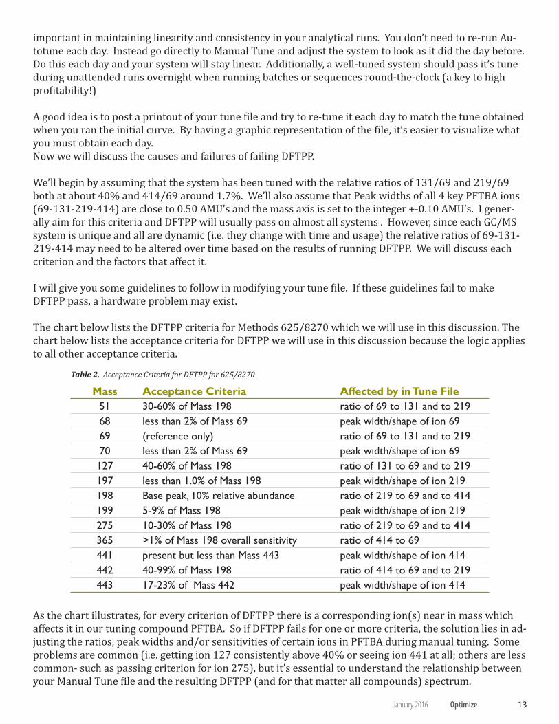
The chart below lists the DFTPP criteria for Methods 625/8270 which we will use in this discussion. The chart below lists the acceptance criteria for DFTPP we will use in this discussion because the logic applies to all other acceptance criteria.
Table 2. Acceptance Criteria for DFTPP for 625/8270
Mass Acceptance Criteria Affected by in Tune File51 30-60% of Mass 198 ratio of 69 to 131 and to 21968 less than 2% of Mass 69 peak width/shape of ion 6969 (reference only) ratio of 69 to 131 and to 21970 less than 2% of Mass 69 peak width/shape of ion 69127 40-60% of Mass 198 ratio of 131 to 69 and to 219197 less than 1.0% of Mass 198 peak width/shape of ion 219198 Base peak, 10% relative abundance ratio of 219 to 69 and to 414199 5-9% of Mass 198 peak width/shape of ion 219275 10-30% of Mass 198 ratio of 219 to 69 and to 414365 >1% of Mass 198 overall sensitivity ratio of 414 to 69441 present but less than Mass 443 peak width/shape of ion 414442 40-99% of Mass 198 ratio of 414 to 69 and to 219443 17-23% of Mass 442 peak width/shape of ion 414
As the chart illustrates, for every criterion of DFTPP there is a corresponding ion(s) near in mass which affects it in our tuning compound PFTBA. So if DFTPP fails for one or more criteria, the solution lies in ad-justing the ratios, peak widths and/or sensitivities of certain ions in PFTBA during manual tuning. Some problems are common (i.e. getting ion 127 consistently above 40% or seeing ion 441 at all; others are less common- such as passing criterion for ion 275), but it’s essential to understand the relationship between your Manual Tune file and the resulting DFTPP (and for that matter all compounds) spectrum.
14 Optimize SPEXCertiPrep.com/ECSJanuary 2016
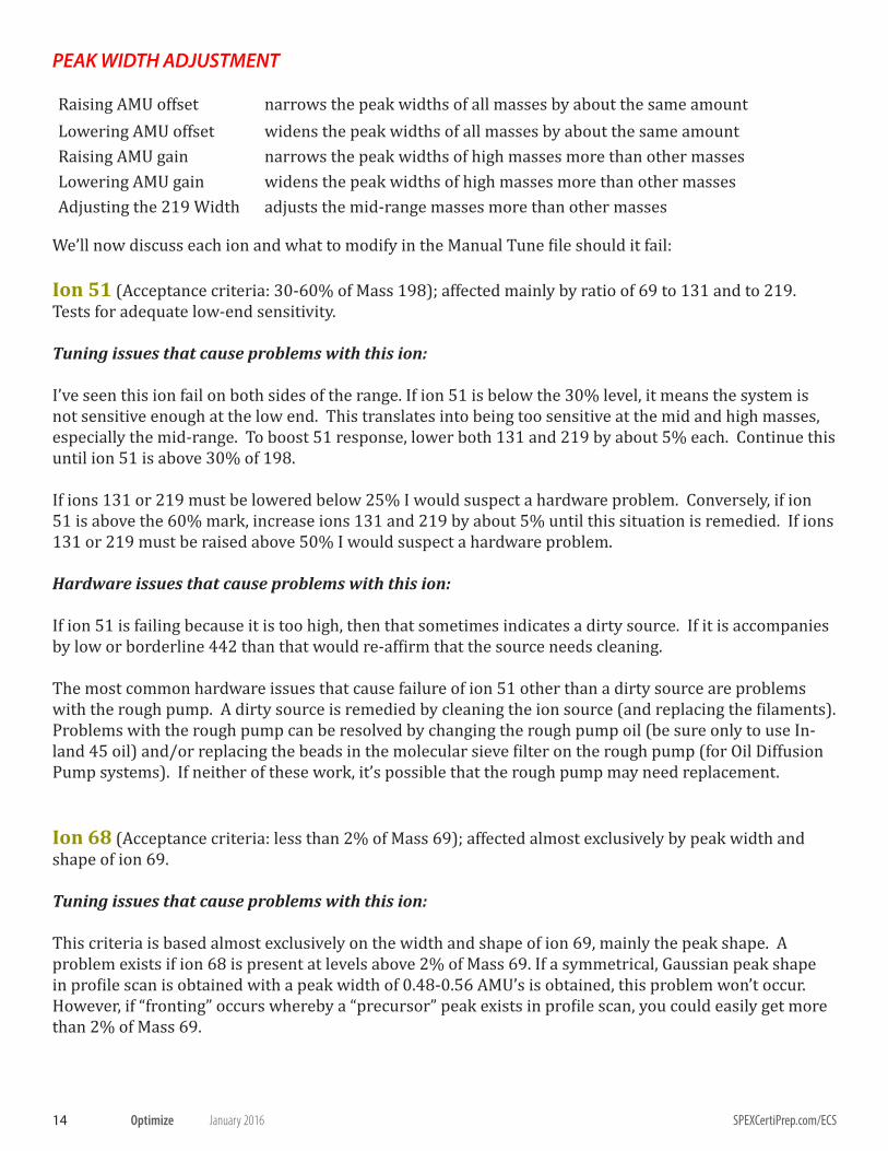
PEAK WIDTH ADJUSTMENT
Raising AMU offset narrows the peak widths of all masses by about the same amountLowering AMU offset widens the peak widths of all masses by about the same amountRaising AMU gain narrows the peak widths of high masses more than other massesLowering AMU gain widens the peak widths of high masses more than other massesAdjusting the 219 Width adjusts the mid-range masses more than other masses
We’ll now discuss each ion and what to modify in the Manual Tune file should it fail:
Ion 51 (Acceptance criteria: 30-60% of Mass 198); affected mainly by ratio of 69 to 131 and to 219. Tests for adequate low-end sensitivity.
Tuning issues that cause problems with this ion: I’ve seen this ion fail on both sides of the range. If ion 51 is below the 30% level, it means the system is not sensitive enough at the low end. This translates into being too sensitive at the mid and high masses, especially the mid-range. To boost 51 response, lower both 131 and 219 by about 5% each. Continue this until ion 51 is above 30% of 198.
If ions 131 or 219 must be lowered below 25% I would suspect a hardware problem. Conversely, if ion 51 is above the 60% mark, increase ions 131 and 219 by about 5% until this situation is remedied. If ions 131 or 219 must be raised above 50% I would suspect a hardware problem.
Hardware issues that cause problems with this ion:
If ion 51 is failing because it is too high, then that sometimes indicates a dirty source. If it is accompanies by low or borderline 442 than that would re-affirm that the source needs cleaning.
The most common hardware issues that cause failure of ion 51 other than a dirty source are problems with the rough pump. A dirty source is remedied by cleaning the ion source (and replacing the filaments). Problems with the rough pump can be resolved by changing the rough pump oil (be sure only to use In-land 45 oil) and/or replacing the beads in the molecular sieve filter on the rough pump (for Oil Diffusion Pump systems). If neither of these work, it’s possible that the rough pump may need replacement.
Ion 68 (Acceptance criteria: less than 2% of Mass 69); affected almost exclusively by peak width and shape of ion 69.
Tuning issues that cause problems with this ion:
This criteria is based almost exclusively on the width and shape of ion 69, mainly the peak shape. A problem exists if ion 68 is present at levels above 2% of Mass 69. If a symmetrical, Gaussian peak shape in profile scan is obtained with a peak width of 0.48-0.56 AMU’s is obtained, this problem won’t occur. However, if “fronting” occurs whereby a “precursor” peak exists in profile scan, you could easily get more than 2% of Mass 69.

15OptimizeJanuary 2016
Hardware issues that cause problems with this ion:
If poor peak shape in manual tune occurs, a hardware problem probably exists: either a dirty source, contaminated quadrupoles, contaminated Entrance Lens, defective Diodes, or defective RFPA electronics being the most likely culprits. Ion 69 (Acceptance criteria: reference only for ions 68 and 70); affected by ratio of 69 to 131 and to 219.
Tuning and Hardware issues that cause problems with this ion:
Very little required, since we tabulate ion 69 so we can evaluate ions 68 and 70 only; whatever we get for ion 69 is satisfactory. The only problem would be if ion 69 were the base peak (instead of ion 198). To solve this increase ions 131 and 219 by about 5-10% until this situation is remedied. If ions 131 or 219 must be raised above 50% I would suspect a hardware problem.
Ion 70 (Acceptance criteria: less than 2% of Mass 69); affected almost exclusively by peak width and shape of ion 69.
Tuning issues that cause problems with this ion:
This criteria is based almost exclusively on the width and shape of ion 69, mainly the peak width. A problem exists if ion 70 is present at levels above 2% of Mass 69. If a symmetrical, Gaussian peak shape in profile scan is obtained with a peak width of 0.48-0.56 AMU’s is obtained, this problem won’t occur. However, if peak widths below 0.45 AMU’s exists in profile scan, you could get more than 2% of Mass 70. The user can adjust peak widths either automatically (i.e. performing Width calibrations through the soft-ware) or manually (my preference) by the following:
Hardware issues that cause problems with this ion:
If poor peak shape in manual tune occurs, a hardware problem probably exists: either a dirty source, con-taminated quadrupoles, contaminated Entrance Lens or defective RFPA electronics being the most likely culprits.
Ion 127 (Acceptance criteria: 40-60% of Mass 198); affected mainly by ratio of 131 to 69 and to 219. Tests for adequate mid-range sensitivity.
Tuning issues that cause problems with this ion:
If ion 127 is indeed below the 40% level, it means the system is not properly tuned in the mid-range.
16 Optimize SPEXCertiPrep.com/ECSJanuary 2016
You may need to try all the following combinations to make 127 pass (you’d be surprised at the ratios I’ve had to achieve to get systems to pass):
1. 131=219 and both between 35-50% of 692. 131=219 and both between 25-35% of 693. 131>219 and both between 35-50% of 694. 131<219 and both between 35-50% of 695. 131>219 and both between 25-35% of 696. 131<219 and both between 25-35% of 69
Hardware issues that cause problems with this ion:
If you can’t get ion 127 to pass, a hardware problem probably exists: either a dirty source, contaminated ceramics, or deteriorated magnet being the most likely culprits.
Ion 197 (Acceptance criteria: less than 1% of Mass 198); affected almost exclusively by peak width and shape of ion 219.
Tuning and Hardware issues that cause problems with this ion:
This is similar to ion 68’s criteria so the discussion is essentially the same. This criterion is based almost exclusively on the width and shape of ion 219, mainly the peak shape. A problem exists if ion 197 is present at levels above 1% of Mass 198. If a symmetrical, Gaussian peak shape in profile scan is obtained with a peak width of 0.48-0.56 AMU’s is obtained, this problem won’t occur. However, if “fronting” occurs whereby a “precursor” peak exists in profile scan, you could easily get more than 1% of Mass 197.
Ion 198 (Acceptance criteria: MUST be the base peak).
Tuning and Hardware issues that cause problems with this ion:
Unless ions 131 and 219 are very low (in which case ion 51 or 69 in DFTPP could end up the base peak) or if ion 414 is way high (in which case ion 442 in DFTPP could end up the base peak) you will always have 198 as the base peak. If you follow the guidelines stated here only a hardware problem can create failure for this criterion.
Ion 199 (Acceptance criteria: 5-9% of Mass 198); affected almost exclusively by peak width and shape of ion 219.
Tuning and Hardware issues that cause problems with this ion:
This criteria is based almost exclusively on the width and shape of ion 219, mainly the peak width. A problem exists if ion 199 is present at levels outside 5-9% of Mass 219. If a symmetrical, Gaussian peak shape in profile scan is obtained with a peak width of 0.48-0.56 AMU’s is obtained, this problem probably won’t occur. However, if peak widths fall below 0.48 AMU’s exists in profile scan, you could get more than 9% of Mass 199; conversely if peak widths rise above 0.56 AMU’s exists in profile scan, you could get less than 5% of Mass 199. The user can adjust peak widths either automatically (i.e. performing Width cali-
17OptimizeJanuary 2016
brations through the software) or manually. This criterion tests for adequate mid-mass resolution.
Ion 275 (Acceptance criteria: 10-30% of Mass 198); affected almost exclusively by peak width and shape of ion 219
Tuning and Hardware issues that cause problems with this ion:
This criterion is based on the ratio of ion 219 to 69 and 414. I’ve only seen this criterion fail once (on the high side) and in that case the cause was a contaminated source. I would say that if it failed on the low side you should raise ion 219’s abundance, and vice versa if it fails on the high side. Failure of this ion is extremely unlikely and would likely be accompanied by failures of several other ions as well.
Ion 365 (Acceptance criteria: >1% of Mass 198); affected by overall sensitivity and high-end sensitivity.
Tuning and Hardware issues that cause problems with this ion:
This is a good one because it is affected by two factors. If ion 365 falls below the required 1% of ion 198, the first thing I would suspect is that the system isn’t sensitive enough. This is especially true if ion 442 was present in adequate abundances. I would rerun DFTPP with a 100V increase in the EMV (Electron Multiplier voltage) and/or lower my Threshold by 50% (usually the former). However, if ion 442 also fails because it’s below the 40% of 198 criteria, I would assume that the failure of 365 was due mainly to inadequate high-end sensitivity rather than inadequate overall sensitivity. See the discussion on ion 442 for details.
Ion 441 (Acceptance criteria: present, but less than Mass 443); affected almost exclusively by peak width and shape of ion 414.
Tuning and Hardware issues that cause problems with this ion:
IMPORTANT NOTE: Ion 441 must be present in the mass spectrum. Some software systems erroneously list the criteria for ion 441 as 0-99% of ion 443, but it should be 1-99% of ion 443 so be sure your soft-ware has the correct criteria.
This criterion is based almost exclusively on the width and shape of ion 414, mainly the peak shape. The most common problem is the total absence of ion 441. If symmetrical, Gaussian peak shape in profile scan along with a peak width of 0.48-0.56 AMU’s for ion 414 are obtained, this problem probably won’t occur. However, if “fronting” occurs whereby a “precursor” peak exists in profile scan, you could easily miss getting any 441 at all. If this situation occurs, a hardware problem probably exists: either a dirty source, contaminated quadrupoles, contaminated Entrance Lens, or defective electronics being the most likely culprits.
Acquisition Method issues that cause problems with this ion:
Another key parameter that affects this ion is the A/D (Analog to Digital) setting in your acquisition method (also called Sampling rate on some systems). You might want to increase the A/D setting such that each scan on your peak is an average of more scans and is a more accurate representation of the true

18 Optimize SPEXCertiPrep.com/ECSJanuary 2016
spectrum. If you are using 2^1=2, try using 2^2=4 for your A/D. If you are using 2^2=4, try using 2^3=8 for your A/D.
Ion 442 (Acceptance criteria: 40-99% of Mass 198); affected mainly by ratio of 414 to 69 and to 219. Tests for adequate high-range sensitivity.
Tuning issues that cause problems with this ion:
This criteria is based on the relative abundance of ion 414. I’ve seen this ion fail on both sides of the range. If ion 442 is below the 40% level, it means the system is not sensitive enough at the high end. This translates into being too sensitive at the mid and low masses, especially the mid-range. To boost 442 response, raise 414 slightly (0.2-0.4%) in conjunction with lowering both 131 and 219 by about 5% each. Continue this until ion 442 is above 40% of 198. If ion 414 must be raised above 3% and ions 131 or 219 must be lowered below 20% I would suspect a hardware problem. Conversely, if ion 442 is above the 99% top level mark, increase ions 131 and 219 by about 5% and lower ion 414 until this situation is rem-edied. If ions 131 or 219 must be raised above 50% or 414 below 0.4% I would again suspect a hardware problem.
Hardware issues that cause problems with this ion:
The inability to get ion 442 above the 40% mark can usually be attributed to: a weak filament, a dirty source, problems with the rough pump, problems with the diffusion pump fluid, or electronics problems (in that order). Try doing a routine PM (preventative maintenance) on the system where you change fil-aments, clean the ion source and replace the rough pump oil and see if that boosts high end sensitivity. If not, then look to the diffusion pump fluid and/or electronics.
Ion 443 (Acceptance criteria: 17-23% of Mass 442); affected almost exclusively by peak width and shape of ion 414.
Tuning and hardware issues that cause problems with this ion:
This criterion is based almost exclusively on the width and shape of ion 414, mainly the peak width. A problem exists if ion 443 is present at levels outside 17-23% of Mass 414. If a symmetrical, Gaussian peak shape in profile scan is obtained with a peak width of 0.48-0.56 AMU’s is obtained, this problem probably won’t occur. However, if peak widths fall below 0.48 AMU’s exists in profile scan, you could get more than 23% of Mass 443; conversely if peak widths rise above 0.56 AMU’s exists in profile scan, you could get less than 17% of Mass 443. The user can adjust peak widths either automatically (i.e. performing width calibrations through the software) or manually. For this mass-range you would predominantly adjust the AMU Gain. This criterion tests for adequate high-mass resolution.
Final Point on DFTPP Tuning
Usually the conventional tunes whereby ions 131 and 219 are close in relative abundance and each around 37-38% of 69 combined with ion 414 around 1.7% of 69 will succeed in passing DFTPP...but NOT always. Hopefully this guide will assist you should you be in a position where DFTPP won’t pass. Keep in mind that the tune file you (or the software) creates affects everything you do- from checking the tune, to calibrating, to processing data (target and non-target) to generating good blanks. A thorough under-standing of the effects and ramifications of tuning are essential to generating high quality data and mini-mizing down-time.

19OptimizeJanuary 2016
Semivolatile systems tend to be more dynamic than Volatile systems due to the contamination found in the extracts. Daily adherence to proper tuning is the key in detecting any degradation in your system at the earliest time.
FINAL WORD ON MANUAL TUNING....
Strive for consistency in all your final results from day to day- keep the ratios of your key ions, the raw abundance of ion 69, the peak width and the mass axes the same from day to day and that will help your system stay linear. Tune with a clean inlet (BNAs) and clean Purge and Trap concentrator (VOAs). Do your injector maintenance (BNAs) prior to manually tuning the MSD.
If you want to become a true GC/MS ace, you should learn to tune your own instrument. You’ll notice I didn’t even address “Target Tune” in this issue because I’ve seen it cause lots of problems with GC/MS systems. Get good at manual tuning- I assure you that it will help you many times in your GC/MS career.
Questions or comments on this or any issue of OPTIMIZE may be emailed to the author at [email protected]

US Address: SPEX CertiPrep, Inc.203 Norcross AvenueMetuchen, NJ 08840Tel: 1-800-LAB-SPEXFax: 732-603-9647E-mail: [email protected]: www.spexcertiprep.com
UK Address: SPEX Europe2 Dalston GardensStanmoreMiddlesex, HA7 1BQ UKTel: +44 (0) 20 8204 6656Fax: +44 (0) 20 8204 6654E-mail: [email protected]: www.spexeurope.com
SPEX CertiPrep supports saving our natural resources.
Go Green!
Please Recycle!