Embed Size (px)
Citation preview

TTC Family Sequential Valve Gate Controller

Manufacturers of large, complex or difficult to fill parts often turn to Sequential Valve Gate Control to solve molding issues. All SVGC applications have hot runner manifold systems with either pneumatic or hydraulic valve gates. Using SVGC the processor has the ability to selectively open or close each valve gate individually to precisely control the material flow front. Filling the cavity in a sequence has the following potential benefits:
Knit line control
Improved straightness
Lighter weight parts
Dimension improvement
Diagnostics
Through extensive input from processors using existing SVGC units, Synventive created a system that provides a clearer understanding of the sequence to ease troubleshooting. One of our graphical screens is shown below, the green portion of the bar indicates that the valve gate is open, the red portion shows that the valve gate is closed before starting the sequence.
Speed
All SVGC applications rely on speed, accuracy and repeatability to produce the best possible part shot after shot. The integrated eight (8) output version monitors each of the 7 digital and 2 analog inputs every millisecond (1 mSec.). As a result the Synventive SVGC module has the ability to open or close each valve gate every millisecond (1 mSec.).
Hot Runner/SVGC Combination
Synventive, long known for hot runner innovation and superior performance, can provide both hot runner control and SVGC in one enclosure with one interface and one menu for both the hot runner and sequence. The integrated sequential hardware can open or close 8, 16 or 32 pneumatic or hydraulic valve gates.
Calibration
Each analog input is easily calibrated on the screen for maximum resolution and accuracy. Set points can be entered in up to four (4) digits. The inputs can be calibrated to only read a very fine portion of the total range if more setpoint clarity is required.
Programmable Alarms (Closed Loop Monitoring)
The controller can be programmed to alarm if the event happens too early or too late based on historical sequences. This time based alarm is selectable and can provide valuable quality control information for a historically open loop control application.
System Rules
Ten (10) system rules clearly define the capabilities and safety requirements demanded by the system during the sequence.
1. Each output can be opened and closed 3 times during the sequence.
2. The “sequence” does not start until the “Cycle Start” input is activated. This starts the timer.
3. When cycle start is activated, the controller will force all outputs closed before starting the sequence.
4. During the “sequence” and after the first valve is opened at least one output must be open at all times. If a close is prevented, it is indicated by a yellow box (summary page). That opportunity to close is lost and the gate will only close if another close event is programmed and can be satisfied.
5. The “sequence” is over and the timer stops timing when the last event has occurred.
6. If the “sequence” does not finish (last event completed), the controller will not restart the “sequence” or the timer with the next “Cycle Start”. To restart one of the following must occur; loss of enable or e-stop or toggle between the maintenance and sequence mode.
7. The sequence of each gate is independent of the others.
8. Each event in the sequence of a gate must occur before the next event is considered by the SVGC.
9. The activation of the E-Stop input or the loss of the enable input causes all gates to immediately go to the closed states and ends the cycle, regardless of sequence programming.
10. Warning: At “Injection” all valve gates can be programmed to be closed. Typically one or more outputs are opened with the first stage of the sequence.
Sequential Valve Gate Control (SVGC) Precisely Control the Material Flow Front
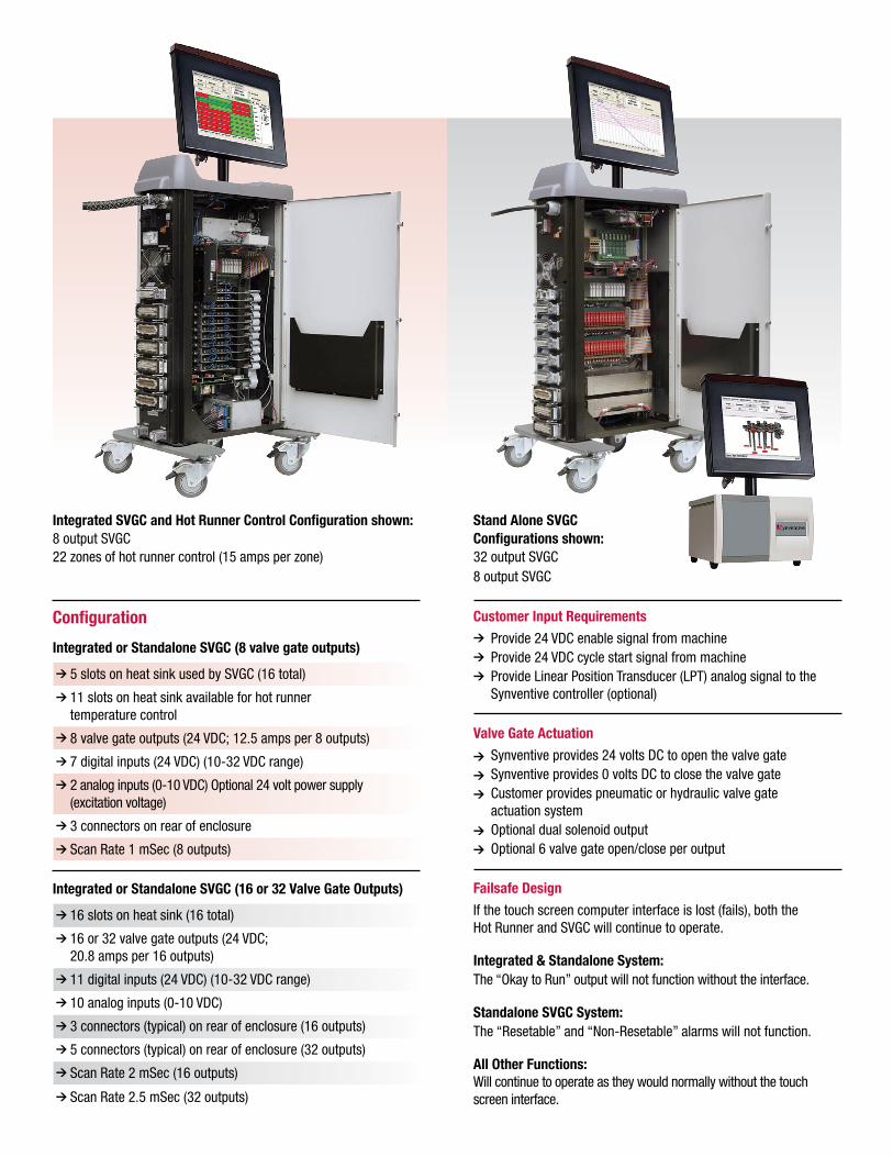
Configuration
Integrated or Standalone SVGC (8 valve gate outputs)
5 slots on heat sink used by SVGC (16 total)
11 slots on heat sink available for hot runner temperature control
8 valve gate outputs (24 VDC; 12.5 amps per 8 outputs)
7 digital inputs (24 VDC) (10-32 VDC range)
2 analog inputs (0-10 VDC) Optional 24 volt power supply (excitation voltage)
3 connectors on rear of enclosure
Scan Rate 1 mSec (8 outputs)
Integrated or Standalone SVGC (16 or 32 Valve Gate Outputs)
16 slots on heat sink (16 total)
16 or 32 valve gate outputs (24 VDC; 20.8 amps per 16 outputs)
11 digital inputs (24 VDC) (10-32 VDC range)
10 analog inputs (0-10 VDC)
3 connectors (typical) on rear of enclosure (16 outputs)
5 connectors (typical) on rear of enclosure (32 outputs)
Scan Rate 2 mSec (16 outputs)
Scan Rate 2.5 mSec (32 outputs)
Customer Input Requirements
Provide 24 VDC enable signal from machine Provide 24 VDC cycle start signal from machine Provide Linear Position Transducer (LPT) analog signal to the Synventive controller (optional)
Valve Gate Actuation
Synventive provides 24 volts DC to open the valve gate Synventive provides 0 volts DC to close the valve gate Customer provides pneumatic or hydraulic valve gate actuation system Optional dual solenoid output Optional 6 valve gate open/close per output
Failsafe Design
If the touch screen computer interface is lost (fails), both the Hot Runner and SVGC will continue to operate.
Integrated & Standalone System:The “Okay to Run” output will not function without the interface.
Standalone SVGC System:The “Resetable” and “Non-Resetable” alarms will not function.
All Other Functions: Will continue to operate as they would normally without the touch screen interface.
Integrated SVGC and Hot Runner Control Configuration shown: 8 output SVGC 22 zones of hot runner control (15 amps per zone)
Stand Alone SVGC Configurations shown: 32 output SVGC 8 output SVGC

Synventive Molding Solutions * 10 Centennial Drive Peabody, MA 01960 USA ) +1 800.367.5662 ) +1 978.750.8065 7 +1 978.646.36008 [email protected]
Synventive Molding Solutions GmbH * Heimrodstraße 10 64625 Bensheim P.O. Box 3123 64615 Bensheim Germany ) +49 (0)6251 9332 0 7 +49 (0)6251 9332 908 [email protected]
Synventive Molding Solutions (Suzhou) Co., Ltd. * 12B Gang Tian Industrial Square Suzhou Industrial Park, 215021 China ) + 86 512 62838870 7 + 86 512 628388908 [email protected]
Your Local Representative
Start Up Procedure
Maintenance Mode
Sequence Mode
5. Events – Edit events – Program sequence 6. Summary – Start machine – Review sequence
7. Events or Tool Screens – Edit events 8. Graph – Review cycle 9. Alarms – Program timeout – Learn alarms – Enable alarms
1. Connect inputs and outputs
2. I/O - Setup - Edit Setup - Mark used inputs and outputs
3. I/O – Calibrate Analog inputs 4. I/O – Change inputs – Open/Close valve gates (test)


![[TTC Rules below Quy Định TTC kéo xuống dưới] · [TTC Rules below – Quy Định TTC kéo xuống dưới] Thus, gossiping or backbiting about other person, staff or students](https://img.pdfslide.us/doc/110x75/5f09d2e47e708231d428a927/ttc-rules-below-quy-nh-ttc-ko-xung-di-ttc-rules-below-a-quy.jpg)