Embed Size (px)
Citation preview

Instruction Manual
VGCTM I Sequential Valve Gate Control


VGCTM SEQUENTIAL VALVE GATE CONTROLINSTRUCTION MANUAL
©INCOE® CORPORATION 2/2009 Pg. www.incoe.com
TABLE OF CONTENTS
1
1 INTRODUCTION 1.1 Programming Pg. 2 1.2 Control Pg. 2 1.3 Signals coming from the Injection Molding Machine Pg. 2 1.4 Connecting signals coming from the press Pg. 2 1.5 Security Pg. 4 1.6 Connections for VGC Sequential Valve Gate Control Cabinet Pg. 5 1.7 Dimensions in. (mm) Pg. 5 1.8 Fuses and Circuit Breakers Pg. 5 1.9 Applicable standards Pg. 5 1.10 Wiring diagram of VGC Sequential Valve Gate Control cabinet Pg. 6 1.11 Machine interface Pg. 7
2 OPERATION 2.1 Calibration Pg. 8 2.2 Configuration of the system Pg. 9 2.2.1 Duration of the Closing signal at the end of the injection cycle Pg. 9 2.2.2 Delay before position control Pg. 9 2.2.3 Prolonging of injection signal Pg. 9 2.2.4 Selection of unit for screw travel Pg. 10 1. Unit in % Pg. 10 2. Unit in mm Pg. 10 3. Unit in cm3 Pg. 10 2.3 Manual mode Pg. 11 2.4 Modify a program Pg. 12 2.5 File management Pg. 14 2.6 Management of alarms: Pg. 15 Select and validate the function ALARM from the main page. 2.7 Main System Parameters Values Pg. 16 2.8 System locking Pg. 16 2.9 Option position control of pins Pg. 16 2.10 List of main spare parts Pg. 18
3 TROUBLEShOOTING 3.1 Troubleshooting Pg. 19
4 WARRANTY 4.1 Warranty Pg. 21
5 CONTACT 5.1 Global Service Pg. 23 5.2 Global Offices Pg. 24

VGCTM SEQUENTIAL VALVE GATE CONTROLINSTRUCTION MANUAL
©INCOE® CORPORATION 2/2009 Pg. www.incoe.com
INTRODUCTION
2
2
1
1.0 DESCRIPTION OF ThE CABINET
These cabinets are designed for the controlling of 4-8- or 12 valve gates. 1.1 PROGRAMMING
Programming a sequence is accomplished with the integrated multi-lingual user interface. This applies to both types of VGC cabinets (keyboard an blue backlit LCD display), offering the following features:
• Programming the actuation of the valve gates.
• Loading / Saving 8 sequence files.
• Manual actuation of the valve gates.
• Display cycle time.
• Display value of screw position. Optional Limit Switches: It is possible to use position sensors and display the valve gate pin positions.
1.2 CONTROL
Actuation of 1 or 2 valve gates opening and closing per cycle:
Each movement can be triggered using one of the following signals :
• Timer function from injection start or hold start.
• Screw position in %, cm3 or in mm.
1.3 SIGNALS COMING FROM ThE INjECTION MOLDING MAChINE
Injection Start Signal is required.
The others signals recomended listed below are optional
• Injection Hold signal.
• Screw position signal.
Important Notice : It is required to connect at least the injection start signal to program a sequence based on time.
For connecting these signals, please refer to the wiring diagram on Page 3.
1.4 CONNECTING SIGNALS COMING FROM ThE PRESS
See diagram on next page.

VGCTM SEQUENTIAL VALVE GATE CONTROLINSTRUCTION MANUAL
©INCOE® CORPORATION 2/2009 Pg. www.incoe.com
1
3
INTRODUCTION

VGCTM SEQUENTIAL VALVE GATE CONTROLINSTRUCTION MANUAL
©INCOE® CORPORATION 2/2009 Pg. www.incoe.com
INTRODUCTION
1. 5 SECURITY
a) Alarm output on open contact, activated in case of: • Fault on hydraulic power pack (not used if no external power pack).
• Fault on injection safety : at least one valve gate must be programmed to the open position at injection start.and during the hole injection cycle.
• Fault on control card.
• Fault on valve gate pin position during the injec-tion cycle time (optional).
b) Input “from hydraulic power pack in “via isolated dry set of contact:
• Indicates to controller that hydraulic pressure is available for the valve gates.
• If the hydraulic power pack is not functionong the controller will not allow the cycle to run.
c) Alarm input on isolated dry set of contact:
• Indicates to the controller that the injection molding machine is currently under alarm. • If this alarm is active the controller will not allow the cycle to run.
4
1

VGCTM SEQUENTIAL VALVE GATE CONTROLINSTRUCTION MANUAL
©INCOE® CORPORATION 2/2009 Pg. www.incoe.com
1
5
1
1.6 CONNECTIONS FOR VGC SEQUENTIAL VALVE GATE CONTROL CABINET
A: Connector for input signals (16 pins 10A female).
B: Connector for alarm inputs and outputs, as well as for security on hydraulic power pack (10 pins 10A female).
C: Connector for commands to valve gates, voltage 24V DC, 1.5 Amps per valve gate (32 pins 10A female).
D: Option : Connector for limit switches on valve gates (32 pins 10A male).
E: Power supply cable inlet 3G2,5mm2 (Supply voltage 230V AC 50/60Hz).
F: Fuse holder with fuse 16A on cabinet.
G: Circuit breaker 16A (switching cabinet on / off).
IMPORTANT NOTICE: When connecting the signals from the press to connector A on cabinet, it is recommended to split 0-10V signals and 0-24V signals. Use a cable with shielded pairs, connect screw position with the first pair and hold signal, injection signal and 0-24V supply with the other pairs.
1.7 DIMENSIONS IN. (MM)
• Cabinet VGC Seq Valve Gate Control for 12 valve gates :
17” (431mm) L x H 8.5” (216mm) H x 18.5” (470mm) D
1.8 FUSES AND CIRCUIT BREAkERS
• Fuse 16A type gI for cabinet (size 10x38 mm).
• Circuit breaker 16A.
• Fuses 6.3A on each control card (size 5x20 mm).
1.9 APPLICABLE STANDARDS
Cabinet VGC Sequential Valve Gate Control is approved for the Specification CE 73/23 “Low voltage” and fullfill the EN 61010-1 standards.
They also comply with the following standards:
Electrical noise industriel environnent : EN 50081-2
Electrical Noise Immunity in industrial environment: EN50082-2
INTRODUCTION
There MUST be a plug on connector B. Use either a dummy plug, or a plug that is using the features intended for Connector B.

VGCTM SEQUENTIAL VALVE GATE CONTROLINSTRUCTION MANUAL
©INCOE® CORPORATION 2/2009 Pg. www.incoe.com
1
1.10 WIRING DIAGRAM OF VGC SEQUENTIAL VALVE GATE CONTROL CABINET
INTRODUCTION
6

VGCTM SEQUENTIAL VALVE GATE CONTROLINSTRUCTION MANUAL
©INCOE® CORPORATION 2/2009 Pg. www.incoe.com
1.11 MAN – MAChINE INTERFACE
OPERATION 1
LCD screen Validate key Direction arrows
Key to validate.
Escape key
Key to erase partially or completely an input.
Alpha-numerical keyboard for inputs.
Display of commands to valve gates :
Command open : green LED on the left is lit.Command close : red LED on the right is lit.
OPTION : Display of position control of limit switches : Control open : green LED on the left is lit.Control close : red LED on the right is lit.
LED for communication control card - CPU
7

VGCTM SEQUENTIAL VALVE GATE CONTROLINSTRUCTION MANUAL
©INCOE® CORPORATION 2/2009 Pg. www.incoe.com
2.0 STARTING UP
Plant power 230V AC 50/60 Hz Single Phases cable supplied.
Make sure that all connections to the backside of the cabinet are correct (command signal, alarms….). Switch the cabinet on with the 16A circuit breaker. The following pages appear after 5 seconds :
Important Notice: When the cabinet VGC Seq Valve Gate Control is not in service, the A connector on the backside of the cabinet must be disconnected in order not to interfear with the signals from the injection machine.
2.1 CALIBRATION
For proper use of the controller with the injection molding machine, it is required to calibrate the screw travel first.
To access the calibration page, simply select the SYST function on white background, validate and then select the SCRCAL function.
Select SCRCAL to calibrate the screw travel.
The following page is displayed.
Validate the function CALIBR to enter the calibration process from this page and enter the calibration values one after the other by moving the screw on the injection machine.From this point, the process must be brought to the end.
Guiding messages for the operator
Notice: The machine number is important information to enter and to confirm which machine the calibration process has been done on the controller.
Please note that if this controller is moved to another machine, it must be recalibrated if you wish to use the screw position signal for programming.
All words preceded by “MES.“ are values read from the injection machine.
All words preceded by “VAL. “ are inputs made by the operator.
OPERATION2
8
VGCTM SEQUENTIAL VALVE GATE CONTROLINSTRUCTION MANUAL
©INCOE® CORPORATION 2/2009 Pg. www.incoe.com
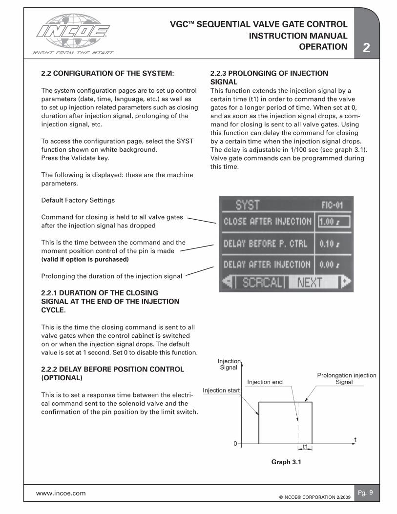
2.2 CONFIGURATION OF ThE SYSTEM:
The system configuration pages are to set up control parameters (date, time, language, etc.) as well as to set up injection related parameters such as closing duration after injection signal, prolonging of the injection signal, etc.
To access the configuration page, select the SYST function shown on white background.Press the Validate key.
The following is displayed: these are the machine parameters.
Default Factory Settings
Command for closing is held to all valve gates after the injection signal has dropped
This is the time between the command and the moment position control of the pin is made (valid if option is purchased)
Prolonging the duration of the injection signal
2.2.1 DURATION OF ThE CLOSING SIGNAL AT ThE END OF ThE INjECTION CYCLE.
This is the time the closing command is sent to all valve gates when the control cabinet is switched on or when the injection signal drops. The default value is set at 1 second. Set 0 to disable this function.
2.2.2 DELAY BEFORE POSITION CONTROL (OPTIONAL)
This is to set a response time between the electri-cal command sent to the solenoid valve and the confirmation of the pin position by the limit switch.
2.2.3 PROLONGING OF INjECTION SIGNALThis function extends the injection signal by a certain time (t1) in order to command the valve gates for a longer period of time. When set at 0, and as soon as the injection signal drops, a com-mand for closing is sent to all valve gates. Using this function can delay the command for closing by a certain time when the injection signal drops. The delay is adjustable in 1/100 sec (see graph 3.1). Valve gate commands can be programmed during this time.
OPERATION 2
Graph 3.1
9

VGCTM SEQUENTIAL VALVE GATE CONTROLINSTRUCTION MANUAL
©INCOE® CORPORATION 2/2009 Pg. www.incoe.com
Press NEXT for accessing further system parameters to select the unit for screw position, date, time, language, etc….
Display and set system date and time
Select language
Modify keyboard password
Selection of Unit for Screw travel
Select MODIF to modify one of these 5 parameters and validate. Possible choices are displayed above the arrows as far as the language and the unit for screw position.Enter the required value with the keyboard for time, date and password.
CAUTION: The programmed sequence is lost if the unit for screw position is changed.
CAUTION: Check the programmed sequence after changing the unit.
2.2.4 SELECTION OF UNIT MEASURE FOR SCREW TRAVEL:
1. Unit in (%): This unit is related to the injected volume of material. 0% is set at injection start and 100% is reached when the screw is empty. This unit is directly linked to the injection shot size of the machine. If a sequence programmed on a machine with an injection unit A is loaded on the controller used on a machine with a different injection unit B, the new shot size must be set so that the values programmed in % remain valid.
2. Unit in (mm):Values programmed using this unit depend on the screw position not on the volume of injected material. This unit does not rely on the shot size but on the calibration of the screw position signal received by the controller. A programmed sequence using this unit relates to the machine and any file using this unit should be modified to be used on a different machine.
3. Unit in (cm3): This unit depends on the calibration of the screw position and on the injected volume of material. It is independent from the shot size. A programmed sequence using this unit can be used on a different machine if the controller has been recalibrated for the new machine.
Advantages and disadvantages are on the compat-ibility of saved sequence files loaded on different injection units:
• Programs in % Recalibration is not required. • Programs in mm: Recalibration is required. New calculation of command values.
• Programs in cm3 Recalibration is required.
OPERATION2
10

VGCTM SEQUENTIAL VALVE GATE CONTROLINSTRUCTION MANUAL
©INCOE® CORPORATION 2/2009 Pg. www.incoe.com
2.3 MANUAL MODE :
The manual mode is to open or close the valve gates manually in order to make sure that everything is functioning before production.
Select and validate the MANU function from the main page. The page below is displayed.
Selection frame
Valve gate output is disabled (OFF)
OPERATION 2
* The shadowed icon means that the valve gate output is disabled (not used). * This valve gate output receives a command for closing during the injection cycle.* The white icon means that the valve gate output is enabled.* A valve gate output under alarm is displayed in this way:
Important notice: Select a valve gate output us-ing the arrows for moving up and down. Select a command using the arrows for moving left or right for opening (OPEN), for closing (CLOSE), or for stopping the preceding command (STOP), for selecting a single valve gate output (SELECT) or all channels (ALL).
OPEN: Permanent command for opening a valve gate.CLOSE: Permanent command for closing a valve gate.STOP: For stopping previous commands for opening or closing.SELECT: To select or unselect a valve gate output.ALL: To select or unselect all valve gate outputs in the configuration.
Important Notice: No valve gate can be opened or closed if the hydraulic power pack is switched off and/or if the alarm contact is validated.
11

VGCTM SEQUENTIAL VALVE GATE CONTROLINSTRUCTION MANUAL
©INCOE® CORPORATION 2/2009 Pg. www.incoe.com
2.4 PROGRAMMING MODE :
2.4.1 MODIFY A PROGRAM:
This mode is to program the movements required for each valve gate during the injection cycle (injection signal, screw position, etc.)
Select and validate PROG for accessing the page for programming from the main menu :The page below is displayed:
Validate MODIF when it appears to select another signal. Then select the required signal with the arrows by moving left or right.Move the cursor on the field to modify values for triggering moments and enter the required value on the alpha-numerical keyboard and validate.
One can select among 3 triggering signals for programming.
OPERATION2
Valve gate number to be programmed
Opening and closing No1 for selected valve gate
Opening and closing No2 for selected valve gate
To program another valve gate, enter the required valve gate number on the alpha-numerical keyboard and validate.
To switch a valve gate on or off, move the cursor accordingly to ON or OFF. Then validate the function MODIF to select from ON or OFF with the arrows. Then validate again to move to the next field.
Example of a program:
Switch on/off valve gate
Triggering signal for opening
Triggering signal for closing
Value for valve gate actuation (in the unit corresponding to the selected command mode)
Cursor
The values for programming are:
1) Injection start: the value to enter is the delay between the injection start signal and the required triggering moment.
2) Hold start: the value to enter is the delay between the hold start signal and the required triggering moment.
3) Screw position: The value to enter depends on the selected unit:
12

VGCTM SEQUENTIAL VALVE GATE CONTROLINSTRUCTION MANUAL
©INCOE® CORPORATION 2/2009 Pg. www.incoe.com
• Unit in %: The value is the percentage of injected volume of material before actuating the valve gate.
• Unit in mm: The value to enter is the stroke of the injection screw before actuating the valve gate (and not the position of the injection screw).
• Unit in cm3: The value to enter is the injected volume of material before actuating the valve gate.
OPERATION 2
Important Notice: Select NONE with the left and right arrows to erase a signal. This action will automatcally erase the selected step and the following if relevant.
Please note that the sequence programmed for a channel is carried out until the injection signal drops. Therefore, it is recommended to erase all lines that are not required.
13

VGCTM SEQUENTIAL VALVE GATE CONTROLINSTRUCTION MANUAL
©INCOE® CORPORATION 2/2009 Pg. www.incoe.com
2.5 FILE MANAGEMENT :
Select and validate the FILE function from the main page.
The page below is displayed :
OPERATION2
The arrow shows the fi le selected in the list
File on a white background: the current sequence originates from this fi le
Various info about the selected fi le
This page is for the management of sequence fi les. Some information like date and time of creation and comments can be saved as well.
The name of the current fi le is displayed in all pages
This fl oppy icon is shown when the current sequence has been modifi ed but has not been saved as a fi le.
NEW: to create a new sequence fi le.
SAVE: to save or modify the selected fi le. The current program is saved as the selected fi le.
LOAD: to load the sequence saved in the selected fi le.
DELETE: to cancel the selected fi le.
Important Notice: • The fi le name on a white background is the cur-rent sequence fi le and is always dispayed in the top right section of all pages in the program.
• Maximum 8 fi les can be saved in this menu FILE. You must delete unused fi les for saving a new fi le.
14

VGCTM SEQUENTIAL VALVE GATE CONTROLINSTRUCTION MANUAL
©INCOE® CORPORATION 2/2009 Pg. www.incoe.com
OPERATION
2.6 MANAGEMENT OF ALARMS:
Select and validate the function ALARM from the main page.
The page hereunder is displayed :
Alarm hydraulic power pack : shows the absence of the external power pack or of the shunt between pins 1 and 6 inside the B connector on the backside of the controller
Alarm external system : alarm contact coming from whatever device around the sequential control cabinet.
Faulty control card : shows that a control card for actuating outputs is faulty.
Fault position control open (valid if option position control is present) : shows that the limit switch did not confirm the actual pin on opening.
Fault position control close (valid if option po-sition control is present) : shows that the limit switch did not confirm the actual pin on closing.
No opening command : shows that no valve gate was programmed to open in the injection cycle. If so the injection cycle is stopped.
Program not valid : shows an error in program-ming (not corresponding to screw calibration for instance, etc…).
This page shows the current alarms.
RESET : to reset both alarm contacts for injection safety.
Press ESC to go back to main page.
Various types of alarms
The LED shows that the corresponding alarm is active
2
15

VGCTM SEQUENTIAL VALVE GATE CONTROLINSTRUCTION MANUAL
©INCOE® CORPORATION 2/2009 Pg. www.incoe.com
2.7 MAIN SYSTEM PARAMETERS VALUES :
Select and validate the function MSPV from the main page
The page below is displayed :
The cycle time and the actual screw position in the selected unit are displayed on this page.
Notice : the percentage shown on this page is expressed for the total screw stroke and 0% means an empty screw.
The status of input signals (injection start, hold start, hydraulic power pack and alarm input) a are displayed above.Press ESC to go back to main page.
2.8 SYSTEM LOCkING :
Select and validate the function CODE from the main page.
The page below is displayed :
It is possible to lock or unlock the system from this page by entering a password with the alpha-numerical keyboard.
A message confirming the current status is dis-played in the top left section of the page once the password has been entered.
The default password factory set is 123456.Use the function SYST and validate with NEXT to modify the password in page 2 of system param-eters.
2 OPERATION
16

VGCTM SEQUENTIAL VALVE GATE CONTROLINSTRUCTION MANUAL
©INCOE® CORPORATION 2/2009 Pg. www.incoe.com
2.9 OPTION POSITION CONTROL OF PINS:
The option position control can be fitted on VGC Sequential Valve Gate Control cabinet to show the actual pin position of each valve gate (open or closed).
An extra function called CONFIG is shown if the option is used. This function enables the position control of the pins.Select and validate CONFIG on a white background from the main page shown below.
Press validate.The page below is displayed:
This arrow confirms the pin is controlled on opening
This arrow confirms the pin is controlled on closing
Important Notice: Use up an down arrows like in manual mode to select a valve gate output. Left and right arrows enable control ON / OFF, on opening (CTLOPN), on closing (CTLCLO), select a single valve gate (SELECT) or select all valve gate(ALL).
ON/OFF: To switch on or off the corresponding valve gate.
CTLOPN: To enable or disable position control on opening. Control open
CTLFER: To enable or disable position control on closing. Control closing
SELECT: To select or unselect a valve gate output.
ALL: To select or unselect all valve gate outputs in the CONFIG page.
OPERATION 2
Then select the line “MODIF PASSWORD” and validate when MODIF is on a white background.The page below is displayed.Follow the procedure as explained.
Enter old password.Enter new password.Confirm new password.
Important Notice: Please use the contact informa-tion if the password has been forgotten. A new procedure will be provided to go back to the fac-tory setting.
17

VGCTM SEQUENTIAL VALVE GATE CONTROLINSTRUCTION MANUAL
©INCOE® CORPORATION 2/2009 Pg. www.incoe.com
2.10 LIST OF RECOMMENDED SPARE PARTS:
Item Description – Part number Quantity
3042 Control card VGC Sequential Valve Gate Control 1
6438 Supply 230V/12-5V – MEAN WELL PD-45A 1
6271 Screen LCD 128x64 – LWM12864D-EW-WCB 1
5455 Fuse type GI 16A - 10x38 mm 1
6272 Supply 230V/24V – 12,5A – SP320-24 1
18
OPERATION2

VGCTM SEQUENTIAL VALVE GATE CONTROLINSTRUCTION MANUAL
©INCOE® CORPORATION 2/2009 Pg. www.incoe.com
3.0 TROUBLEShOOTING:
3.1 TROUBLEShOOTING:
IMPORTANT NOTICE
• Any repair on the controller should be carried out by qualified personal.
• Any component being replaced must have the same specification.
TROUBLEShOOTING 3
Failure
• No hydraulic pres-sure
• No command to valve gate(s)
• Cycle does not start
• No command tovalve gates/cycle does not start
Display
“Alarm hydraulic pressure”(Displayed in alarm page).
“Failure control card” (dis-played in alarm page) and no blinking yellow LED for communication on control card.
No action and the cause are displayed in the alarm page.
The blinking yellowcommuncationlights arefunctioning.
Causes
• No hydraulic pressure connected.
• Control card not connected or out of order.
• The press does not deliver the analog signal required.• The wiring of signals from the press is not correct.• Other alarms pre-vent cycle start (eg. : no hydraulic pressure...)• The programmed sequence is not correct.
• Do have a 24vinjection start signal
Solutions
• Check connection and if the signal “Hydraulic on” is properly wired to cabinet (plug B).
• Check supply to con-trol card and the link to motherboard. Test outputs on control card.• Replace control card.
• Check input signals from the press.• Check if this wiring is correct.• Check if no other alarms on alarm page.• In the sequence, at least one gate must be open when injection starts.
• Make sure the dummyplug is installed inconnector “B” on theback of the VGC unit.
19

VGCTM SEQUENTIAL VALVE GATE CONTROLINSTRUCTION MANUAL
©INCOE® CORPORATION 2/2009 Pg. www.incoe.com
TROUBLEShOOTING3
Default
Green LED for open-ing or red LED for closing does not light
2 gates are con-trolled simultane-ously when only one should be controlled
Machine alarm when cabinet is switched off
Signal
Go to alarm page where the alarm is de-scribed (for instance: Alarm on hydraulic power pack, etc….)
The 2 LED’s for com-mands to open or close are lighted simultaneously when only one should be lighted.
Reading wrong value for screw position by the press.
Causes
• No hydraulic pres-sure supplied• Alarm switch acti-vated.• Fuse 6.3A on con-trol card blown
• Check wiring of the command wires connector to the solenoids.• Check if fault on control card.
• Plug A connected to VGC Sequential Valve Gate Control cabinet.
Solutions
• Check wiring and if the contact “hydraulic power on” is connected properly.• Check if no alarm is currently activated.• Replace fuse on con-trol card 6,3 A.
• Wire properly.• Replace control card.
• Disconnect “A” con-nector at backside of VGC Sequential Valve Gate Control cabinet.
20

VGCTM SEQUENTIAL VALVE GATE CONTROLINSTRUCTION MANUAL
©INCOE® CORPORATION 2/2009 Pg. www.incoe.com 21
4WARRANTY
1 Applicable Law and jurisdiction
These general terms and conditions apply to all proposals and quotations submitted by Seller, to all purchase orders received by Seller, and to all goods and services sold by Seller, except as other-wise specifically provided in a document signed by Seller. This sale or any sale resulting herefrom consists only of these terms and conditions and those in other documents which are referred to herein or are attached hereto or in a document subsequently signed by Seller and referencing this transaction (all of which constitute the “Agreement“). THE AGREEMENT SHALL BE GOVERNED, CONSTRUED AND ENFORCED UNDER THE LAW OF THE STATE OF MICHIGAN INCLUDING THE UNIFORM COMMERCIAL CODE IN FORCE ON THE INITIAL DATE OF THE AGREEMENT (“UCC“), EXCEPT AS PROVIDED HEREIN. The U.N. Convention on the International Sales of Goods shall not apply. Any services to be provided hereunder, whether or not they are otherwise ancillary to and part of a sale of goods (as separate units), shall be considered ancillary to a sale of goods and the UCC shall apply to all goods and services to be provided hereunder (“Goods“). ThE COURTS OF MIChIGAN ShALL hAVE EXCLUSIVE jURISDICTION OVER ThE PARTIES AND ThE CLAIMS ARISING UNDER OR RELATED TO ThE AGREEMENT. The parties stipulate to the convenience of Michigan courts in general, and Oakland Circuit Court in particular, as to all litigation. Any declaration of unenforceability of a provision shall be as narrow as possible and shall not affect the enforceability of the other provisions.
2 Formation, Integration and Modification
A. The Agreement supersedes all previous quotations and agreements pertaining to the Goods. Delivery to Seller of the Buyer‘s acceptance of a Seller’s quotation (according to its terms), Seller‘s actions in reliance on Buyer‘s oral acceptance of a written or oral quotation, or Buyer‘s receipt of the Goods, will constitute a binding contract under the terms of the Agreement. The Agreement is subject to Seller‘s revocation or cancellation without liability until it is approved by Seller at its home office. Notice of such approval may be furnished to the Buyer in the form of an acknowledgment, shipment, or other form of express approval.
B. An order submitted by Buyer orally or in a purchase order or other writing (whether or not it contains terms or conditions modifying, adding to, repugnant to, or inconsistent with these Terms and Conditions), may be accepted, approved or filled by Seller, but any resulting contract and the liabilities or obligations of Seller shall be determined solely by the Agreement, and (unless the Seller otherwise advises Buyer in writing) notice is hereby given that Seller objects to any such terms or conditions in Buyer‘s purchase order or other writing. Seller shall not be deemed to have in any way enlarged or modified its liabilities or obligations under the Agreement by filling such order or by failing to further object to Buyer‘s terms or conditions.
C. The Agreement is a final, complete and exclusive statement of the Agreement of the parties. THE SELLER IS WILLING TO NEGOTIATE WRITTEN CHANGES TO THESE TERMS AND CONDI-TIONS, BUT RESERVES THE RIGHT TO MAKE AN ADJUSTMENT IN THE PRICE OF THE GOODS. No modifications, limitations, waivers or discharge of the Agreement or any of its terms shall bind Seller unless in writing and signed by Seller‘s authorized employee at its home office. Notwithstand-ing anything to the contrary in this Agreement, no modifications, limitation, waiver or discharge of any provision of the Agreement shall affect the Buyer‘s liabilities to Seller accrued prior thereto. Seller may correct unilaterally any mathematical and typographical errors in the Agreement. Typed provisions of the Agreement take precedence over printed provisions. A course of performance, course of dealing, or customs in the trade shall not constitute a modification or waiver by Seller of any right by Seller.
D. The Agreement is only for the benefit of the parties, except all disclaimers and limitations ap-plicable to Seller shall be for the benefit of Seller‘s agents, employees, contractors, and suppliers. If any provisions are determined to apply to third parties, all other provisions including limitations, waivers, and disclaimers shall also apply.
3 Prices, Payment and Risk of Loss
A. Prices contained in Seller‘s published price lists, if any, are subject to change without notice. Prices contained in individual written quotations or proposals are firm only for a period of thirty (30) days from the date of the quotation after which Buyer should inquire of Seller as to their validity and request a written confirmation or revision. Prices do not include taxes and Buyer shall pay all applicable sales or other taxes levied with respect to Goods (and replacements) and the Agreement, unless exempt therefrom. All prices are in United States dollars. Buyer shall pay all government fees levied on the installation and inspection of the Goods. Buyer shall pay upon receipt all invoices rendered by Seller for any such items Seller may pay and for the Goods.
B. This Agreement is for a shipment contract and the Goods shall be delivered F.O.B. Seller‘s dock. Whether or not Seller prepays shipping charges, risk of loss passes to Buyer upon tender of the Goods to a carrier. Seller‘s breach of the Agreement shall not affect the passing of the risk of loss to Buyer notwithstanding any provision of law to the contrary.
C. Seller may unilaterally increase prices to cover increased costs (plus reasonable overhead and profit) of design, materials, and manufacturing required by changes requested by Buyer after the date of any quotation.
D. All amounts not paid to Seller when due shall incur a carrying charge of 1.5% per month to the extent allowed by law and otherwise at the highest written contract rate allowed by law.
E. All amounts due on installation or other event which requires the action or cooperation of Buyer which Buyer fails to supply timely shall become due upon such failure.
4 Delivery
Shipping dates are estimates based on Seller‘s present engineering and manufacturing capacity and scheduling, and may be revised by Seller upon receipt or scheduling of Buyer‘s order. All shipping dates are approximate and shall be computed from the date of entry of the order on Seller‘s books. All shipping dates are further subject to Seller‘s prompt receipt from Buyer of a written purchase order or acceptance, letter of credit, down payment, and other conditions as specified in the Agreement, and of all drawings, information and approvals necessary to provide Goods and to grant any credit proposed in the Agreement.
5 Delay of Shipment or Performance Excused for Various Reasons
A. If shipment of any item or other performance by Seller is delayed at the request of or due to the fault of Buyer, Seller may at its option hold the item at the place of manufacture at the risk and expense of the Buyer from the time it is ready for shipment. In the event of any such delay in shipment, full and final payment for an item shall be due and payable thirty (30) days after the Buyer is notified that the item is ready for shipment. If the Seller is unwilling to accommodate the Buyer by holding such item, the Buyer shall accept shipment immediately.
B. Dates for Seller‘s performance are estimates only. In addition, the Seller shall not be in default because of its delay or failure to deliver or perform resulting, in whole or in part, from: (i) any foreign or domestic embargoes, seizures, acts of God, insurrections, war, or the adoption or enactment of any law, ordinance, regulation, ruling or order, or (ii) the lack of usual means or transportation, fires, floods, explosions, strikes or any other accidents, contingencies, or events, at the Seller‘s or its supplier‘s plant or elsewhere (whether or not beyond the Seller‘s control) which directly or indirectly interfere with, or render substantially more burdensome, Seller‘s production, delivery, or performance.
6 Inspection, Testing and Rejection
A. If the Agreement expressly provides for Buyer‘s inspection and/or acceptance of the Goods, Seller‘s standard test procedures conducted by Seller‘s representative shall be the criteria for inspection and/or acceptance, unless other specific procedures have been specified in the Agreement.
B. All drawings, specifications, technical documentation, samples, prototypes and Goods shall be deemed approved and/or accepted by Buyer if Buyer does not provide a written objection and/or rejection within seven (7) days of receipt or other reasonable time established by Seller. Any objection and/or rejection by the Buyer must be in writing and state with specificity all defects and non-conformities upon which Buyer will rely to support its rejection. ALL DEFECTS AND NON-CONFORMITIES WHICH ARE NOT SO SPECIFIED ARE WAIVED.
7 Installation and Start Up
All Goods shall be assembled and installed by and at the expense of the Buyer. Seller may furnish, upon request and without additional cost or liability to Seller, written instructions for installing, maintaining, and operating the Goods. At Buyer‘s request and cost, Seller may furnish personnel and equipment to assist in the installation and/or start up of the Goods. Buyer shall pay Seller its prevailing per diem rates for such personnel and equipment plus reasonable transportation, food, lodging and other travel expenses. Buyer shall have competent supervisory, maintenance and operating personnel present when Seller‘s personnel are performing such services.
8 Software License
The Seller grants the Buyer, for its internal use only, a non-exclusive perpetual license (“License“) of all user manuals, software programs, firmware, and storage media (“Software“) provided by the Seller in conjunction with the Goods with which the Software is provided, for the sole purpose of the operation of the Goods. This License terminates automatically if Buyer is in default of its obligations. The Software may be provided in machine readable object code only. Licensee may make and keep one copy of the object code, if provided by Seller, for backup purposes. When making a copy, the Buyer shall reproduce all Seller‘s copyright or patent notices in all forms originally included in the Software. Buyer shall not make any effort to obtain or reproduce the Software‘s source code. Title and all ownership rights to the Software remain with Seller, its licensors, or its suppliers. The Software is the proprietary information and trade secret of the Seller or its licensors, whether or not any portion thereof is or may be validly copyrighted or patented. The License may not be assigned nor transferred by Buyer except as a part of a transfer of the Goods with-out the written consent of Seller which may be withheld. The Software is provided for the Buyer‘s internal use only and the Buyer shall maintain the confidential nature of the Software and related materials and protect them against disclosure or improper use. Buyer shall pay all taxes based on the Software or use of the Software, however designated or levied, except those based on Seller‘s net income. All disclaimers and limitations applicable to the Goods apply to the License.
9 General Express Warranties
A. Seller warrants to Buyer only, that Goods (or portions thereof manufactured by Seller) shall be free from manufacturing defects in materials and workmanship which are discovered within the warranty period, subject to the disclaimers and limitations of the Agreement. This is not a war-ranty of performance, but a limited warranty as to the condition of the Goods at the beginning of the warranty period. The warranty period, measured from date of shipment by Seller, shall be: one year for hot runner systems and components (other than heaters and thermocouples); three years for defects causing leakage for DFQ bushings; three years for cast (pro-rated) and DF heaters; one year pro-rated for screen pacs, fast cycle bushings, and KX heaters; six months for thermocouples; two years for temperature and valve gate controllers (reduced to six months for electronic components); one year for quick mold change products; and 90 days for all other Goods. The percentage of the replacement cost shall be reduced by three percent for each full month from 90 days after the date of shipment for the cast heater warranty and by 50% and 75% at the end of six and nine months, respectively, after shipment for the screen pac, fast cycle bushings, and KX heater warranty. Because the Goods may be subject to a wide variety of use, installation, maintenance and cleaning, the warranty is only against such defects and not against any other failures such as, but not limited to, those due to wear and tear, and normal maintenance and perishable items are excluded from this warranty against defects.
B. Seller warrants to Buyer that the Goods will be as described in the Agreement in all material respects, subject to the limitations stated herein and Seller‘s published and internal standards; however, Seller retains the right to change the dimensions, composition, design, performance, color and appearance of the Goods without liability if, in its judgment, the change is non material. Seller may, in its discretion, also rely on any generally accepted industry standards.
C. Seller‘s warranties shall apply only if the Goods: (i) have been installed, maintained, and used in conformity with instructions furnished by Seller from time to time, if any; (ii) have been subjected to normal use for the purpose for which Goods were designed;
INCOE® Corporation – GENERAL TERMS AND CONDITIONS OF SALE

VGCTM SEQUENTIAL VALVE GATE CONTROLINSTRUCTION MANUAL
©INCOE® CORPORATION 2/2009 Pg. www.incoe.com
(iii) have not been subjected to misuse, negligence, or accident; and, (iv) have not been altered or repaired by persons other than Seller in any respect which, in the judgment of Seller, adversely affects the condition or operation of the Goods.
10 Patent Express Warranties
Seller shall defend and indemnify Buyer from any claim which asserts that the Goods or their inherent methods of operation, intrinsically, infringe any United States patent, except as to a claim based on Buyer‘s use of the Goods as a step in an overall process or as an element in an overall combination. Seller‘s obligation shall not apply to a claim based on Goods or portions thereof specified, designed, or manufactured by Buyer. Buyer shall notify Seller promptly of any assertions of patent infringement and provide Seller with assistance and information requested by Seller, or Seller shall have no further obligation to defend or indemnify. Seller shall defend with its counsel or other counsel of its choice and shall have the sole right, without consultation with Buyer, to take all action Seller deems appropriate to prosecute or settle such claims. Seller‘s exclusive obligation to indemnify as to Goods declared to infringe is limited to the acquisition of a license, the replacement of Goods with non-infringing goods, the modification of the Goods so that they are non-infringing, or the return of the purchase price and shipping costs in exchange for the Goods, as Seller may elect. This section states the Seller‘s entire and exclusive obligation regarding patent infringement.
11 Disclaimer and Limitation of Express Warranties
There are no express warranties other than those contained in the Agreement. Any representations as to performance and other matters, except as contained in the Agreement, were for illustrative purposes only and do not constitute a warranty. Whether or not the Goods are to be used exclusively by Buyer, there shall be no third party beneficiaries to the express warranties contained herein. Seller does not warrant any portion of the Goods not manufactured by or not furnished by Seller (whether or not specified by Buyer), but Seller shall assign to Buyer upon request all assignable warranties of Seller‘s suppliers re-lated to such Goods. All descriptions, shipping specifications and illustrations of the Goods or the Seller and its quality and other systems and capabilities in catalogues, brochures and price lists or otherwise provided by the Seller are intended for general guidance only and the Seller is not responsible for any errors or omissions therein or for any loss or damage resulting from reliance on them. Seller does not warrant that it or the Goods are in compli-ance with any entity, organization or industry standards, guidelines, or procedures unless specifically contained in the Agreement.
12 Remedy and Limitation of Seller‘s Liability
A. Defective or non-conforming Goods discovered and returned during the warranty period shall be repaired, or replaced by Seller without any additional charge and shipped to Buyer, FOB Seller‘s plant, for reinstallation by Buyer at its cost, subject to the terms hereof. The warranty obligation of Seller is limited to the repair or replacement at Seller‘s plant of any part of the Goods which Buyer shall, within the warranty period, return to Seller, with transportation charges prepaid by Buyer, and which Seller shall determine upon examination to be defective or not in conformity with the express warranties con-tained herein. In lieu of repair or replacement, if Seller elects, Seller may, upon return of such Goods and making a determination of non conformity or defect, keep the Goods and refund the purchase price. Buyer‘s remedies shall be limited (even in the event of Seller‘s default of its warranty obligations) exclusively to those provided in this section. UNDER NO CIRCUMSTANCES ShALL SELLER BE LIABLE FOR CONSEQUENTIAL OR INCI-DENTAL DAMAGES. Buyer waives any causes of action or theories of liability including, but not limited to, those arising under contract, tort, strict liability, product liability, statutes, or otherwise, except as specifically provided by the UCC as modified and limited herein. The replacement or repair of Goods by the Seller does not give rise to any new warranty except the warranty period provided for herein shall be extended by the length of any period from the date the defective or non conforming Goods are received by the Seller until the date repaired or replacement Goods are delivered to Buyer.
B. Buyer must contact Seller requesting warranty coverage plus a return authorization number and other instructions for the return of Goods to Seller or other instructions. If requested by Seller, Buyer shall issue a new purchase order or amendment to Seller for replacement parts, subject to Seller issuing a credit memo if Buyer’s claim for warranty coverage is approved. Buyer must comply with Seller’s return instructions (including return of the Goods) within 30 days or the claim shall be deemed conclusively to have been abandoned. Buyer is responsible for properly tagging, identifying, and packing returned Goods. Goods returned without compliance with the above procedures shall be returned to the sender at sender’s cost.
13 Disclaimer of Implied Warranties
ThE SELLER DISCLAIMS ALL IMPLIED WARRANTIES (OThER ThAN GOOD TITLE) IN-CLUDING BUT NOT LIMITED TO ThOSE OF FIT¬NESS FOR A PARTICULAR PUR-POSE, MERChANTABILITY, AND NON-INFRINGEMENT. Seller does not warrant the Goods will comply with the requirements of any safety or environmental code or regula-tion of any federal, state, municipality or other jurisdiction beyond the specific express warranties in this Agreement.
14 Parts, Service and Training Performed by Seller
All warranty and non-warranty parts, inspection, labor, service, software, and training, if any, provided by the Seller or its agents and contractors (including those provided under purchase orders subsequent to the Agreement) related to the Goods are subject to all limitations and disclaimers of warranties and remedies provided in the Agreement. The Seller may have access to the Goods during or after installation of the Goods. The Seller is not under any duty to inspect the Goods for any defects or any improper use or modification of the Goods nor to correct or advise the Buyer of any such condition, use or modification, which is observed. Any notification which may be given is voluntary and subject to all limitations and disclaimers in the Agreement.
15 User‘s Responsibility for Safety
It is Buyer‘s or other user‘s responsibility to provide all proper dies, devices, tools, train-ing, and other means that may be necessary to effectively protect all personnel from serious bodily injury which otherwise may result from the method of particular installa-tion, use, operation, or service of the Goods. Manuals furnished by Seller; ANSI Safety Standards; EPA, OSHA and similar state regulations; and other sources should be used by Buyer to insure the safe use of the Goods. If Buyer fails to comply with the obligations set forth in this section, Buyer shall indemnify and save Seller harmless from any liability or obligation incurred by Seller to persons injured directly or indirectly in connection with the operation of the Goods and all warranties of Seller shall become automatically void.
16 Indemnification
Buyer shall indemnify the Seller from any and all third party claims, damages, and expenses (including reasonable attorney fees) under theories of tort, product liability, negligence (ordinary or gross), warranty, contract, statute, or otherwise arising out of the use, storage, sale, processing or other disposition of the Goods, supplies or materials used in connection with the Goods, or parts manufactured with the Goods, if the action or inaction of the Buyer or its employees, customers or agents, or the Buyer‘s design specifications, were a material or proximate cause of injuries or damages giving rise to claims against the Seller.
17 Consequential, Incidental, and Other Damages
BUYER AND THIRD PARTIES SHALL NOT BE ENTITLED TO ANY CONSEQUENTIAL, PUNITIVE, EXEMPLARY, OR INCIDENTAL DAMAGES, AS DEFINED IN THE UCC OR OTHERWISE. This limitation shall be enforced regardless of whether Seller has defaulted in its warranty or other obligations. Any legal inability to limit or restrict the right of the Buyer or a third party to such damages shall not affect the right of Seller to indemnification hereunder, and under no circumstance shall Buyer recover more than the purchase price.
18 Security Interest, Power of Attorney
In addition to any security interest granted by the UCC, the Buyer hereby grants a se-curity interest to the Seller in all Goods and documents related thereto and proceeds and products therefrom to secure all obligations of the Buyer to the Seller, whether or not arising under the Agreement. Buyer shall sign financing statements evidencing the security interest as reasonably requested by Seller, or Seller may file a copy of the Agreement or portion thereof as a financing statement. Buyer grants Seller an irrevocable power of attorney to sign Buyer‘s name to a financing statement if necessary or convenient to perfect Seller‘s security interest. In case of a default by Buyer, Seller may peaceably enter the premises of the Buyer and others to repossess or render inoperable all Goods in which it has a security interest.
19 Proprietary Information
A. Buyer acknowledges that any information disclosed to Seller has not and will not be confidential or a trade secret unless clearly and conspicuously noted on the disclosure, or in some other writing delivered to Seller at or prior to the time of the disclosure. Otherwise, Seller shall be under no obligation to refrain from using in its business any information, manufacturing processes or unpatented disclosures which may pass to it from Buyer in the performance of the Agreement
B. All proposals, plans and other information furnished by the Seller in bidding, negotiating and performing the Agreement, are confidential and the property of Seller and shall not be shown or disclosed to any other bidder, and shall not be shown or disclosed to any third party or used by Buyer except as may be necessary for the selection or use of the Goods.
C. Any invention or other information developed by Seller in the performance of the Agreement shall remain the property of Seller.
20 United States Government Regulations
The Buyer shall not engage in any transaction with respect to the Goods which violates any statute or regulation of the United States of America.
21 Certifications
Seller certifies that any Goods produced in the United States shall be produced in com-pliance with all applicable requirements of Sections 6, 7 and 12 of the U.S. Fair Labor Standards Act, and of the regulations and orders of the U.S. Department of Labor is-sued under Section 14 thereof. No other certifications or waivers regarding payments to Seller‘s suppliers or laborers are required.
22 Time for Bringing Action
Any proceeding by the Buyer for breach of the Agreement or any other right against Seller arising from or in connection with the payment cannot be filed nor maintained unless: (i) it is commenced within one (1) year after the cause for action has accrued; (ii) Buyer has given timely written notice to Seller of its claim as provided herein; and (iii) Buyer deposits the unpaid portion of the purchase price with the tribunal pending final adjudication. An action shall accrue no later than shipment of the Goods.
#330439 (2/21/01)
INCOE® Corporation – GENERAL TERMS AND CONDITIONS OF SALEWARRANTY4
22

VGCTM SEQUENTIAL VALVE GATE CONTROLINSTRUCTION MANUAL
©INCOE® CORPORATION 2/2009 Pg. www.incoe.com
GLOBAL SERVICE 5
22
5.1 GLOBAL SERVICE:
In case of problem or for any further information, please use the contact information bellow, or visit www.incoe.com.
INCOE® North AmericaSupport: T: + 1 (248) 556-7790 F: + 1 (248) 556-7799 E: [email protected]
INCOE® EuropeSales & Support T: + 49 (0) 6074-8907-0 F: + 49 (0) 6074-8907-310 E: [email protected]
INCOE® China | ShanghaiSales & Support T: + 86 (21) 5818-6300 F: + 86 (21) 5818-6303 E: [email protected]
INCOE® South AmericaSales & Support T: + 55 (11) 4538-2445 F: + 55 (11) 4524-5690 E: [email protected]
INCOE® Hong KongSales & Support Sales & Support T: + 852 2790-8840 F: + 852 2790-8411 E: [email protected]
INCOE® SingaporeSales & Support T: + 65 (6) 515-5300 F: + 65 (6) 861-1163 E: [email protected]
INCOE® China | DongguanSales & Support T: + 86 (769) 8535-5881 F: + 86 (769) 8542-2998 E: [email protected]
© INCOE Corporation 2/2009
PDF copies of this manual are available to download on our website at :
www.incoe.com/manuals
23

VGCTM SEQUENTIAL VALVE GATE CONTROLINSTRUCTION MANUAL
©INCOE® CORPORATION 2/2009 Pg. www.incoe.com
GLOBAL OFFICES 5
23
INCOE® Europe
INCOE® China | Shanghai
INCOE® South America
INCOE® Hong Kong
INCOE® Singapore
INCOE® China | Dongguan
INCOE® Corporation1740 East Maple RoadTroy, Michigan 48083USA
Main: T: + 1 (248) 616-0220 F: + 1 (248) 616-0225 E: [email protected]
Sales: T: + 1 (248) 556-7770 F: + 1 (248) 616-0227 E: [email protected]
Support: T: + 1 (248) 556-7790 F: + 1 (248) 556-7799 E: [email protected]
INCOE® International Inc. Europe Carl-Zeiss-Straße 47D-63322 Rödermark Germany
Sales & Support T: + 49 (0) 6074-8907-0 F: + 49 (0) 6074-8907-310 E: [email protected]
INCOE® International Brasil, Ltda.Rua Eugenio Ulhano, 335Jardim VirginiaItatiba, SP 13257-480Brasil
Sales & Support T: + 55 (11) 4538-2445 F: + 55 (11) 4524-5690 E: [email protected]
INCOE® (H.K.) Ltd.1205 Leader Industrial Centre57-59 Au Pui Wan StreetFo Tan, Shatin, N.T.Hong Kong
Sales & Support T: + 852 2790-8840 F: + 852 2790-8411 E: [email protected]
INCOE® Hotrunners (Shanghai) Co., Ltd.399 Xuanzhong Road, Building 16Nanhui Industrial ParkShanghai 201314China
Sales & Support T: + 86 (21) 5818-6300 F: + 86 (21) 5818-6303 E: [email protected]
INCOE® International Inc.Room B, 5/F, Hao Yun Building2nd Huan RoadChangan Town, DongguanGuangdong, China
Sales & Support T: + 86 (769) 8535-5881 F: + 86 (769) 8542-2998 E: [email protected]
INCOE® North America
INCOE® Sin gapore Pte Ltd.8, Boon Lay Way #03-02TradeHub 21609964 SingaporeSingapore
Sales & Support T: + 65 (6) 515-5300 F: + 65 (6) 861-1163 E: [email protected]
5
24


©INCOE® CORPORATION 2/2009 Pg. www.incoe.com
www.incoe.com
©INCOE® CORPORATION 5/2009