Embed Size (px)
Citation preview
ISSN No: 2309-4893
International Journal of Advanced Engineering and Global Technology Vol-2, Issue-7, July 2014
SPEED CONTROL OF INDUCTION MOTOR WITH & WITHOUT MULTI-
LEVEL INVERTER USING V/F CONTROL
T.Sripal Reddy Head of EEE Department
Sarada Institute of Technology & Science, Khammam, AP, India.
Dr. B V Sanker Ram Prof. EEE Department
JNT University, Hyderabad, AP, India
Dr K.Raghu Ram Laqshya Institute of
Technology & Science, Khammam, A.P, India
I. INTRODUCTION
This thesis proposes a speed control for induction motors without and with multi-level inverter. In this proposed method, V/F based speed control of Induction Motor drive have been simulated using MATLAB. The simulated results have shown improved performance over without Multi-level inverter & PI controller. It has been seen that SVPWM technique generate lesser Harmonic distortion in the output voltage and current applied to the phases of an induction motor. Owing to its simplicity this strategy can be used as backup control strategy in the event of sensor failure.
II. LITERATURE SURVEY Induction machines (IM) have been
widely used in a variety of industrial and residential applications. Right from its inception its ease of manufacture and its robustness have made it a very strong candidate for electromechanical energy conversion device. Induction motor is existing from fractional horsepower ratings to megawatt levels. To control the induction machine there are different types of control strategies are used.
The most commonly used control strategies are constant V/f control and vector control. In constant V/f control the working principle is based on the constant relation
between voltage and frequency. By applying a specific phase voltage and frequency to induction machine, it can settle down at a desired speed. However, the speed control of conventional constant V/f controls lacks
accuracy due to the existence of the rotor slip. This results in the increase of error between reference speed and actual speed. This method requires additional voltage and current sensors, so the complexity of the system has been increased.
To overcome this problem vector control method is preferred. The vector control algorithm is based on two currents. An induction motor can be modeled most simply using two quadrature currents rather than the familiar three phase currents actually applied to the motor. These two currents called direct (Id) and quadrature (Iq) are responsible for producing flux and torque respectively in the motor. In addition, at least two current sensors and one position sensor is necessary to meet the minimum feedback requirements of vector control. As a result, the failure of the sensor or even the drift of system parameters could potentially result in system malfunction.
This Thesis has simple, cost-effective and reliable control strategy as a backup control strategy to continue operate the system in case of failure of current and voltage feedback sensors. In this method the space
839 www.ijaegt.com
ISSN No: 2309-4893
International Journal of Advanced Engineering and Global Technology Vol-2, Issue-7, July 2014
vector modulation technique has been used because it generates less harmonic distortion in the output voltages and or currents applied to the phases of an AC motor and to provide more efficient use of supply voltage compared with sinusoidal modulation technique. The fuzzy logic bases intelligent controller is used instead of the PI controller, excellent control performance can be achieved even in the presence of parameter variation and drive non-linearity.
III. INDUCTION MOTOR
Basic Construction and Operating Principle:
Like most motors, an AC Induction Motor has a fixed outer portion, called the stator and a rotor that spins inside with a carefully engineered air gap between the two. Virtually all electrical motors use magnetic field rotation to spin their rotors.
In an AC Induction Motor, one set of electromagnets is formed in the stator because of the AC supply connected to the stator windings. The alternating nature of the supply voltage induces an Electromagnetic Force (EMF) in the rotor (just like the voltage is induced in the transformer secondary) as per Lenz’s law, thus generating another set of electromagnets; hence the name – Induction Motor. Interaction between the magnetic field of these electromagnets generates twisting force, or torque. As a result, the motor rotates in the direction of the resultant torque. STATOR:
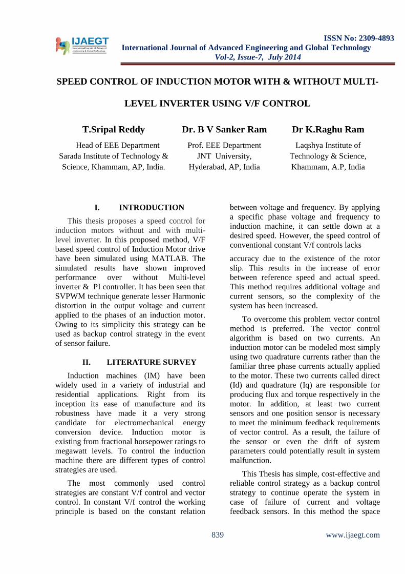
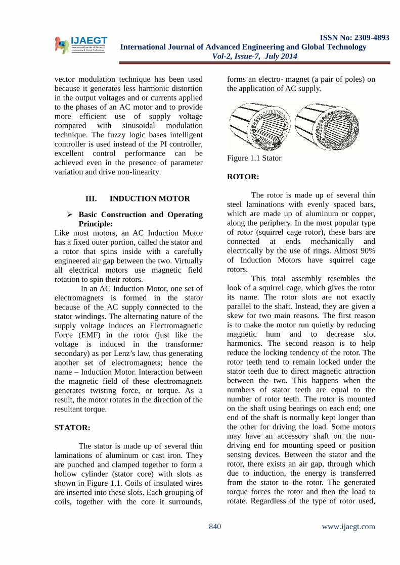
The stator is made up of several thin laminations of aluminum or cast iron. They are punched and clamped together to form a hollow cylinder (stator core) with slots as shown in Figure 1.1. Coils of insulated wires are inserted into these slots. Each grouping of coils, together with the core it surrounds,
forms an electro- magnet (a pair of poles) on the application of AC supply.
Figure 1.1 Stator ROTOR:
The rotor is made up of several thin steel laminations with evenly spaced bars, which are made up of aluminum or copper, along the periphery. In the most popular type of rotor (squirrel cage rotor), these bars are connected at ends mechanically and electrically by the use of rings. Almost 90% of Induction Motors have squirrel cage rotors.
This total assembly resembles the look of a squirrel cage, which gives the rotor its name. The rotor slots are not exactly parallel to the shaft. Instead, they are given a skew for two main reasons. The first reason is to make the motor run quietly by reducing magnetic hum and to decrease slot harmonics. The second reason is to help reduce the locking tendency of the rotor. The rotor teeth tend to remain locked under the stator teeth due to direct magnetic attraction between the two. This happens when the numbers of stator teeth are equal to the number of rotor teeth. The rotor is mounted on the shaft using bearings on each end; one end of the shaft is normally kept longer than the other for driving the load. Some motors may have an accessory shaft on the non-driving end for mounting speed or position sensing devices. Between the stator and the rotor, there exists an air gap, through which due to induction, the energy is transferred from the stator to the rotor. The generated torque forces the rotor and then the load to rotate. Regardless of the type of rotor used,
840 www.ijaegt.com
ISSN No: 2309-4893
International Journal of Advanced Engineering and Global Technology Vol-2, Issue-7, July 2014
the principle employed for rotation remains the same.
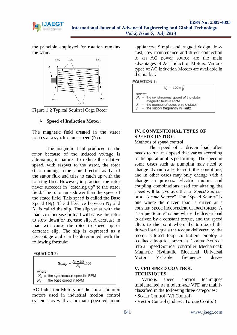
Figure 1.2 Typical Squirrel Cage Rotor Speed of Induction Motor:
The magnetic field created in the stator rotates at a synchronous speed (NS).
The magnetic field produced in the rotor because of the induced voltage is alternating in nature. To reduce the relative speed, with respect to the stator, the rotor starts running in the same direction as that of the stator flux and tries to catch up with the rotating flux. However, in practice, the rotor never succeeds in “catching up” to the stator field. The rotor runs slower than the speed of the stator field. This speed is called the Base Speed (Nb). The difference between NS and Nb is called the slip. The slip varies with the load. An increase in load will cause the rotor to slow down or increase slip. A decrease in load will cause the rotor to speed up or decrease slip. The slip is expressed as a percentage and can be determined with the following formula:
AC Induction Motors are the most common motors used in industrial motion control systems, as well as in main powered home
appliances. Simple and rugged design, low-cost, low maintenance and direct connection to an AC power source are the main advantages of AC Induction Motors. Various types of AC Induction Motors are available in the market.
IV. CONVENTIONAL TYPES OF SPEED CONTROL Methods of speed control
The speed of a driven load often needs to run at a speed that varies according to the operation it is performing. The speed in some cases such as pumping may need to change dynamically to suit the conditions, and in other cases may only change with a change in process. Electric motors and coupling combinations used for altering the speed will behave as either a "Speed Source" or a "Torque Source". The "Speed Source" is one where the driven load is driven at a constant speed independent of load torque. A "Torque Source" is one where the driven load is driven by a constant torque, and the speed alters to the point where the torque of the driven load equals the torque delivered by the motor. Closed loop controllers employ a feedback loop to convert a "Torque Source" into a "Speed Source" controller. Mechanical: Magnetic Hydraulic Electrical Universal Motor Variable frequency drives V. VFD SPEED CONTROL TECHNIQUES
Various speed control techniques implemented by modern-age VFD are mainly classified in the following three categories: • Scalar Control (V/f Control) • Vector Control (Indirect Torque Control)
841 www.ijaegt.com
ISSN No: 2309-4893
International Journal of Advanced Engineering and Global Technology Vol-2, Issue-7, July 2014
• Direct Torque Control (DTC) Scalar Control
In this type of control, the motor is fed with variable frequency signals generated by the PWM control from an inverter using the feature rich PIC micro microcontroller. Here, the V/f ratio is maintained constant in order to get constant torque over the entire operating range. Since only magnitudes of the input variables – frequency and voltage – are controlled, this is known as “scalar control”. Generally, the drives with such a control are without any feedback devices (open loop control). Hence, a control of this type offers low cost and is an easy to implement solution. In such controls, very little knowledge of the motor is required for frequency control.
Thus, this control is widely used. A disadvantage of such a control is that the torque developed is load dependent as it is not controlled directly. Vector Control This control is also known as the “field
oriented control”, “flux oriented control” or “indirect torque control”. Using field orientation (Clarke-Park transformation), three-phase current vectors are converted to a two-dimensional rotating reference frame (d-q) from a three-dimensional stationary reference frame. The “d” component represents the flux producing component of the stator current and the “q” component represents the torque producing component. These two decoupled components can be independently controlled by passing though separate PI controllers.
Direct Torque Control (DTC)
The difference between the traditional
vector control and the DTC is that the DTC has no fixed switching pattern. The DTC switches the inverter according to the load needs. Due to elimination of the fixed
switching pattern (characteristic of the vector and the scalar control), the DTC response is extremely fast during the instant load changes. Although the speed accuracy up to 0.5% is ensured with this complex technology, it eliminates the requirement of any feedback device. The heart of this technology is its adaptive motor model. This model is based on the mathematical expressions of basic motor theory. This model requires information about the various motor parameters, like stator resistance, mutual inductance, saturation co efficiency, etc.
The algorithm captures all these details at the start from the motor without rotating the motor. But rotating the motor for a few seconds helps in the tuning of the model. The better the tuning, the higher the accuracy of speed and torque control. With the DC bus voltage, the line currents and the present switch position as inputs, the model calculates actual flux and torque of the motor. These values are fed to two-level comparators of the torque and flux, respectively.
The output of these comparators is the torque and flux reference signals for the optimal switch selection table. Selected switch position is given to the inverter without any modulation, which means faster response time. The external speed set reference signal is decoded to generate the torque and flux reference. Thus, in the DTC, the motor torque and flux become direct controlled variables and hence, the name – Direct Torque Control.
VI. INTRODUCTION
Matlab (Matrix laboratory) is an interactive software system for numerical computations and graphics. As the name suggests, Matlab is especially designed for matrix computations. • Matlab program and script files always have filenames ending with ".m"; the programming language is exceptionally
842 www.ijaegt.com
ISSN No: 2309-4893
International Journal of Advanced Engineering and Global Technology Vol-2, Issue-7, July 2014
straightforward since almost every data object is assumed to be an array. Graphical output is available to supplement numerical results. M-FILE PROGRAMMING M files
MATLAB allows users to write their own functions using the MATLAB language. This functionality allows you to execute the same code multiple times without having to type it out, line by line, multiple times in the command prompt. All that is to be done is call the function from the MATLAB command prompt and MATLAB will execute all the code in the function until its completed.
To save work and return to it later, see comments and even leave code in that didn't work Using an M-File all the time is especially helpful.
Program Development
Procedures and tools used in creating, debugging, optimizing, and checking in a program
Working with M-Files
Introduction to the basic MATLAB program file
M-File Scripts and Functions
Overview of scripts, simple programs that require no input or output, and functions, more complex programs that exchange input and output data with the caller
Function Handles Packaging the access to a function into a function handle, and passing that
handle to other functions
Function Arguments
Handling the data passed into and out of an M-file function, checking input data, passing variable numbers of arguments
Calling Functions Calling syntax, determining which function will be called, passing different types of arguments, passing arguments in structures and cell arrays, identifying function dependencies
SIMULINK Simulink is a software package for modeling, simulating, and analyzing dynamical systems. It supports linear and nonlinear systems, modeled in continuous time, sampled time, or a hybrid of the two. For modeling, Simulink provides a graphical user interface (GUI) for building models as block diagrams, using click-and-drag mouse operations. Models are hierarchical, top-down and bottom-up approaches are used for building models. The system can be viewed at a high level, then double-click on blocks to go down through the levels to see increasing levels of model detail. This approach provides insight into how a model is organized and how its parts interact. After defining a model, simulation is done, using a choice of integration methods, either from the SIMULINK menus or by entering commands in MATLAB's command window. Using scopes and other display blocks, we can see the simulation results while the simulation is running. In addition, we can change parameters and immediately see what happens, for "what if" exploration.
843 www.ijaegt.com
ISSN No: 2309-4893
International Journal of Advanced Engineering and Global Technology Vol-2, Issue-7, July 2014
The simulation results can be observed in the MATLAB workspace for post processing. Simulink can be used to explore the behavior of a wide range of real-world dynamic systems, including electrical circuits, shock absorbers, braking systems, and many other electrical, mechanical, and thermodynamic systems.
Simulating a dynamic system is a two-step process with Simulink. First, we create a graphical model of the system to be simulated, using Simulink's model editor. The model depicts the time-dependent mathematical relationships among the system’s inputs, states, and outputs. Then, we use Simulink to simulate the behavior of the system over a specified time span. Simulink uses information that you entered into the model to perform the simulation.
VII. MODELLING
DYNAMIC MODELLING OF INDUCTION MOTOR
Consider a space vector Yss of stator voltage,
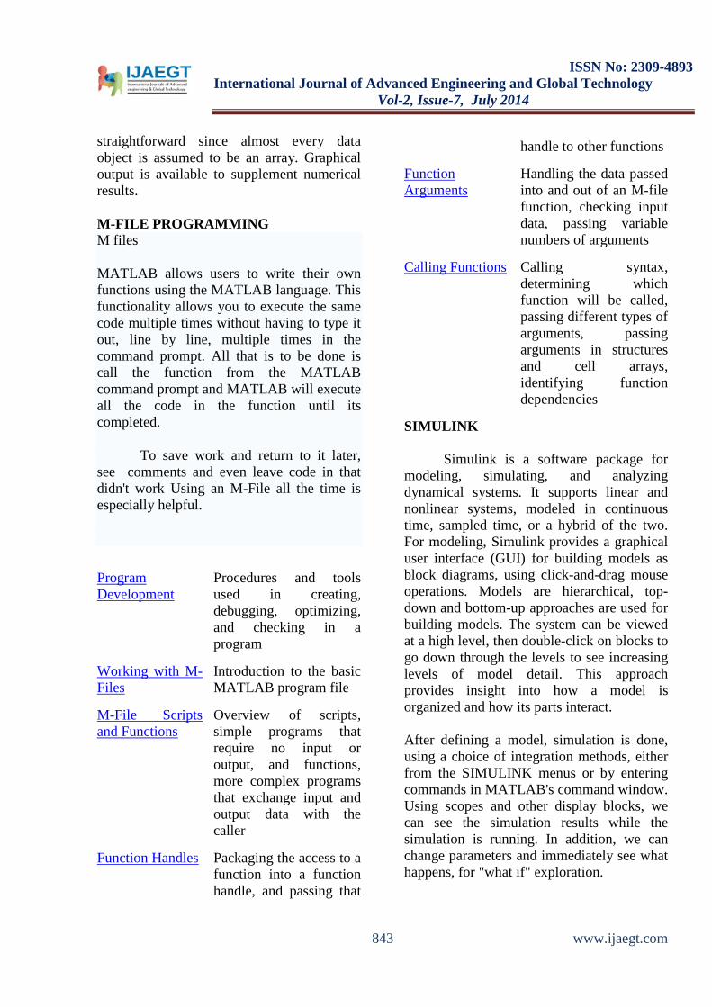
current and flux linkage. Ys s = (2/3) (Ya + α Yb + α 2 Yc) Where α = exp (j2П/3) The above transform being reversible Ya = Re (Ys s), Yb = Re (α 2 Ys s), Yc = Re (α Ys s). Voltage equations on the stator with respect to stationary reference frame Vs s = Rs Is s + p λ s s Voltage equations for rotor on rotor reference frame are: Vr’ = Rr’ Ir’ + p λ r’ = 0
Figure 4.1 Dynamic Equivalent Circuits on a Stationary Reference Frame Need For Transformation of Frames: • The voltage equations describes the
performance of induction and synchronous machine
• We found that some of the machine inductances are functions of the rotor speed, where upon the coefficients of the differential equations which describe the behavior of these machines are time varying except when the rotor is stalled.
• A change of variables is often used to reduce the complexity of these differential equations
• There are several changes of variables which refers machine variables to a frame of reference which rotates at a n arbitrary angular velocity.
It is very convenient to transform actual rotor variables (Vr’, Ir’, λr’) on a rotor reference frame into new variables (Vrs, Irs, λrs) on a stator reference frame. Rotor reference frame to stator reference frame is: Ir s = (1/n) exp (jθ ) Ir’ λr s = n exp (jθ ) λr’ Rr = n2Rr’ Therefore the stator equation with respect to stationary reference frame is: Vs s = Rs Is s + p λs s
The rotor equation with respect to stationary reference frame is: 0 = Rr Ir s + (p – jω0) λr s Where ω0 = pθ0 ; speed of motor in electrical frequency unit The flux linkage equations are given as:
844 www.ijaegt.com
ISSN No: 2309-4893
International Journal of Advanced Engineering and Global Technology Vol-2, Issue-7, July 2014
λs s = Ls Is s + Lm Ir s
λr s = Lm Is s + Lr Ir s
Where Ls = Lls + Lm Lr = Llr + Lm Dynamic model of induction motor on a stationary (stator) reference frame Vs s = (Rs + Ls p) Is s + Lm p Ir s 0 = (Rr + Lr (p - jωo)) Ir
s + Lm (p – jω0) Is s
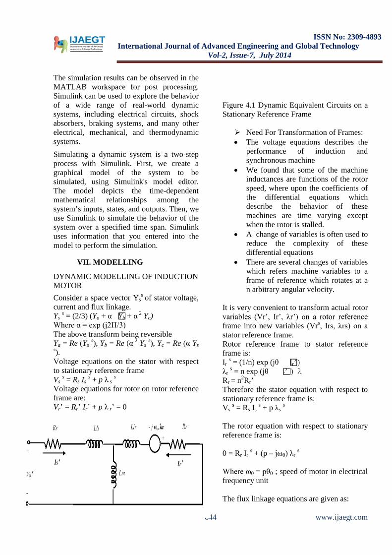
For a arbitrary reference frame rotating at a speed ωa
Figure 4.2 Dynamic Equivalent Circuit on an Arbitrary Reference Frame Rotating at ω. Y a = exp (- j ωa) Y s
Reconstructing the equations: Vs a = (Rs + Ls p) Is a + Lm p Ir a + jωa λs a 0 = (Rr + Lr p) Ir a + Lm p Is a + j (ωa - ωo) λr a, Again reconstructing the equation: Vs
a = Rs Is a + p ( Ls Is a + Lm Ir a)+ jωaλsa
0 = Rr Ir a + p (Lm Is a + Lr Ir a )+ (jωa – jωo)λra
Since λs a = Ls Is
a + Lm Ira
λr a = Lm Isa + Lr Ir a we can write the above
equations as: Vs
a = Rs Is a + pλs a + ja λs a 0 = Rr Ir a + pλr a + j (ωa - ωo) λr a
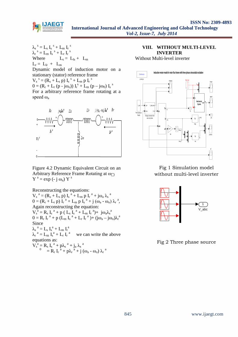
VIII. WITHOUT MULTI-LEVEL INVERTER
Without Multi-level inverter
Fig 1 Simulation model
without multi-level inverter
Fig 2 Three phase source
Tl
Induction motor model in rotor flux frame with three phase sinosoidal excitation
2Te
1wm
wf
2*pi*f
wb
voltages torque
speed
Continuous
powergui
f(u)
mag
f(u)
ias
currents
V_abc
theta_e
V_alpha_beta
V_dq
Voltage conversion from abc to dq frame
V_abc
Three phase pu Supply
Step load
Te
Tl
wmMechanicalSystem
1s
vs
wm
Te
is
wf
em
wm
ias
Is_magi_dq
Te
theta_e
theta_e
1V_abc
845 www.ijaegt.com
ISSN No: 2309-4893
International Journal of Advanced Engineering and Global Technology Vol-2, Issue-7, July 2014
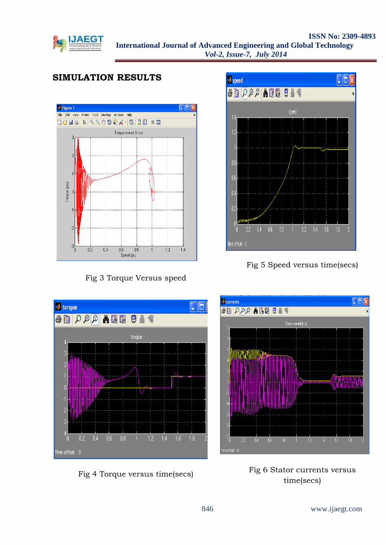
SIMULATION RESULTS
Fig 3 Torque Versus speed
Fig 4 Torque versus time(secs)
Fig 5 Speed versus time(secs)
Fig 6 Stator currents versus time(secs)
846 www.ijaegt.com
ISSN No: 2309-4893
International Journal of Advanced Engineering and Global Technology Vol-2, Issue-7, July 2014
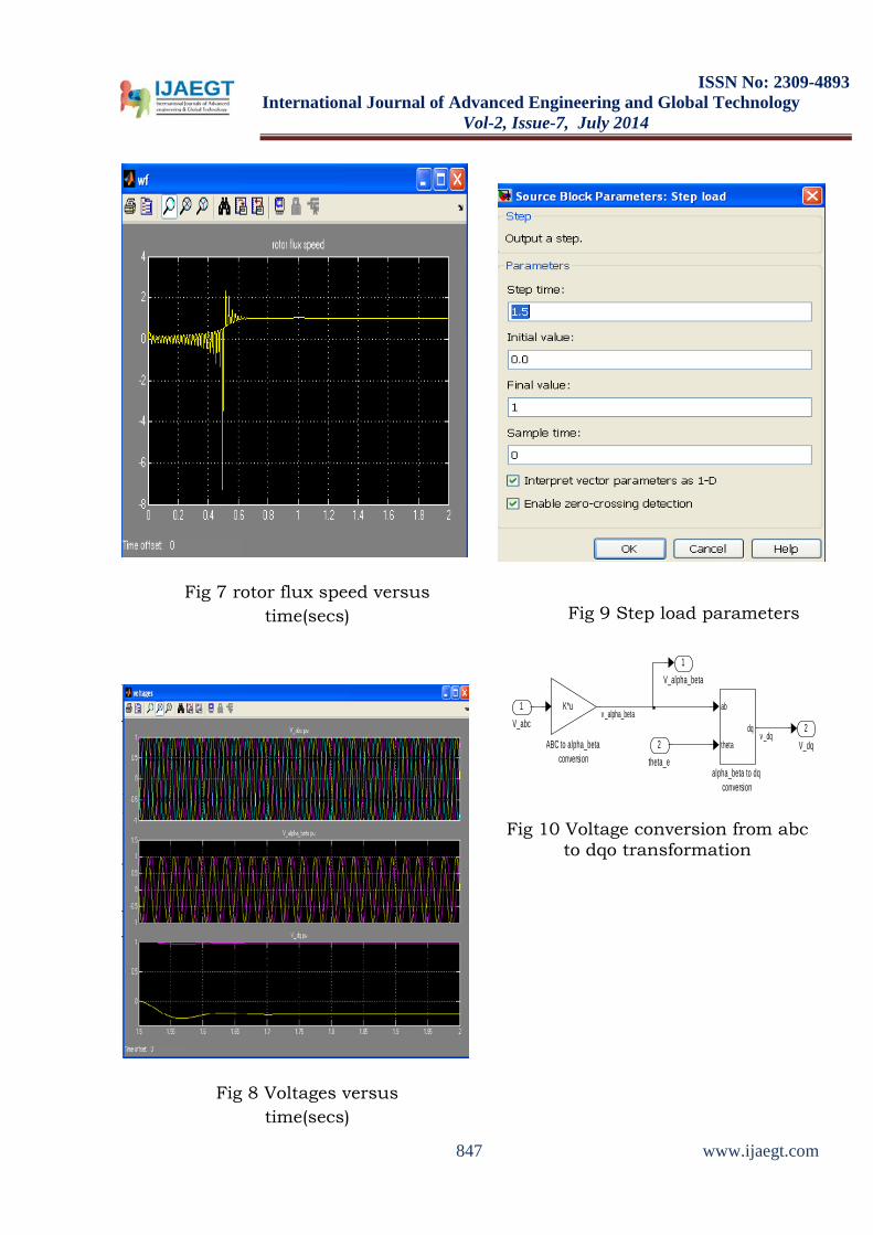
Fig 7 rotor flux speed versus time(secs)
Fig 8 Voltages versus time(secs)
Fig 9 Step load parameters
Fig 10 Voltage conversion from abc
to dqo transformation
2V_dq
1V_alpha_beta
ab
theta
dq
alpha_beta to dq conversion
K*u
ABC to alpha_beta conversion
2theta_e
1V_abc
v _alpha_beta
v _dq
847 www.ijaegt.com
ISSN No: 2309-4893
International Journal of Advanced Engineering and Global Technology Vol-2, Issue-7, July 2014
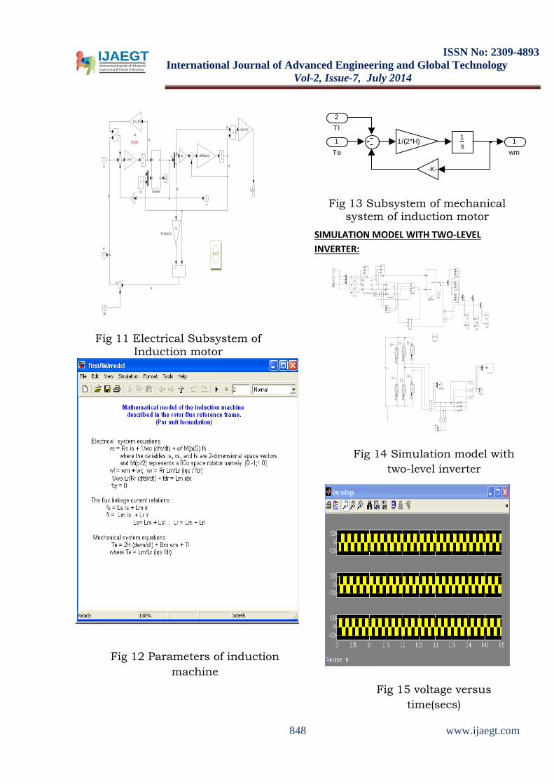
Fig 11 Electrical Subsystem of
Induction motor
Fig 12 Parameters of induction machine
Fig 13 Subsystem of mechanical
system of induction motor
SIMULATION MODEL WITH TWO-LEVEL INVERTER:
Fig 14 Simulation model with
two-level inverter
Fig 15 voltage versus time(secs)
STATORfs
is
3wf
2is
1Te
[0 -1;1 0]* u
rot
MODEL
0
fqr
f s
f r
is
ir
flux-current
-K-Rr*Lm/(Lm+Llr)
1s1
s
Lm/(Lm+Llr)
2*pi*fwb*Rr/(Lm+Llr)Lm
Rs
em
2wm
1vs
ids
wf
wfwr
iqs
iqs
f dr
1wm
1s
-K-
1/(2*H)
2Tl
1Te
t6
t5
t4t3
t2t1
gm
12
s6
gm
12
s5
gm
12
s4
gm
12
s3
gm
12
s2
gm
12
s1
Continuous
powergui
phase votage
phase current1
phase current
0.86
m
mag
theta1
S/H pulse
Vq0
Vd0
local vector gen.
line voltage
sector
s/w state selector
gating signals
gating signal generator
abc
fourier
pi/2
delta
12
c phase
12
b phase
a
b
c
sector
mag
theta1
abc -> mag + local theta1
12
a phase
v+-
v+-
v+-
v+ -
v+ -
v+ -
Vdc2
f(u)
Vc_ref
f(u)
Vb_ref
f(u)
Va_ref
In1
In2
In3
In4
Out1
Subsystem
Scope3
Scope1Scope
[gc2]
Goto9
[gc1]
Goto8
[gb2]
Goto5
[gb1]
Goto4
[gc4]
Goto11
[gc3]
Goto10
[gb2]
[gb1]
[gc4]
[gc3]
[gc2]
[gc1]
i+ -
i+ -
i+ -
1
Constant
<= 1e-005
[1 0]
0
[0 1]
-
848 www.ijaegt.com
ISSN No: 2309-4893
International Journal of Advanced Engineering and Global Technology Vol-2, Issue-7, July 2014
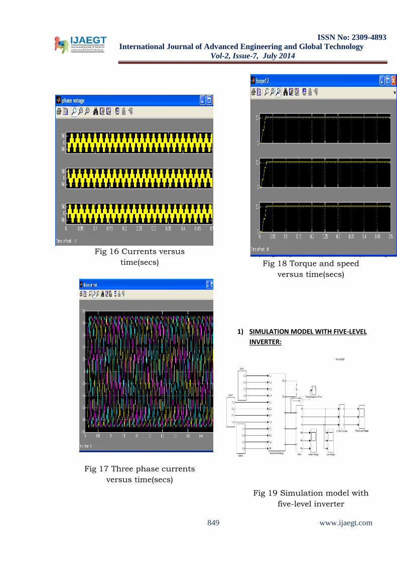
Fig 16 Currents versus
time(secs)
Fig 17 Three phase currents versus time(secs)
Fig 18 Torque and speed
versus time(secs)
1) SIMULATION MODEL WITH FIVE-LEVEL INVERTER:
Fig 19 Simulation model with five-level inverter
849 www.ijaegt.com
ISSN No: 2309-4893
International Journal of Advanced Engineering and Global Technology Vol-2, Issue-7, July 2014
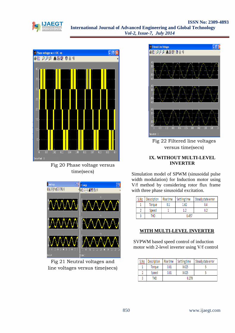
Fig 20 Phase voltage versus
time(secs)
Fig 21 Neutral voltages and
line voltages versus time(secs)
Fig 22 Filtered line voltages
versus time(secs)
IX. WITHOUT MULTI-LEVEL INVERTER
Simulation model of SPWM (sinusoidal pulse width modulation) for Induction motor using V/f method by considering rotor flux frame with three phase sinusoidal excitation.
WITH MULTI-LEVEL INVERTER
SVPWM based speed control of induction motor with 2-level inverter using V/f control
850 www.ijaegt.com
ISSN No: 2309-4893
International Journal of Advanced Engineering and Global Technology Vol-2, Issue-7, July 2014
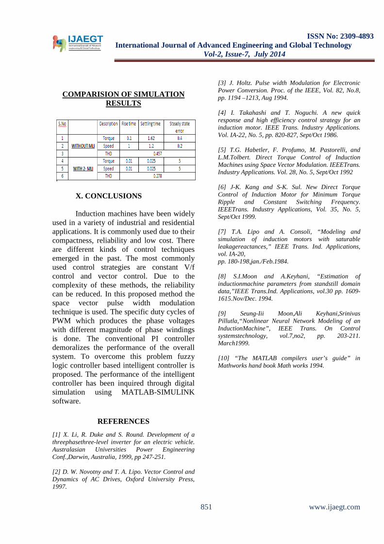
COMPARISION OF SIMULATION RESULTS
X. CONCLUSIONS
Induction machines have been widely used in a variety of industrial and residential applications. It is commonly used due to their compactness, reliability and low cost. There are different kinds of control techniques emerged in the past. The most commonly used control strategies are constant V/f control and vector control. Due to the complexity of these methods, the reliability can be reduced. In this proposed method the space vector pulse width modulation technique is used. The specific duty cycles of PWM which produces the phase voltages with different magnitude of phase windings is done. The conventional PI controller demoralizes the performance of the overall system. To overcome this problem fuzzy logic controller based intelligent controller is proposed. The performance of the intelligent controller has been inquired through digital simulation using MATLAB-SIMULINK software.
REFERENCES [1] X. Li, R. Duke and S. Round. Development of a threephasethree-level inverter for an electric vehicle. Australasian Universities Power Engineering Conf.,Darwin, Australia, 1999, pp 247-251. [2] D. W. Novotny and T. A. Lipo. Vector Control and Dynamics of AC Drives, Oxford University Press, 1997.
[3] J. Holtz. Pulse width Modulation for Electronic Power Conversion. Proc. of the IEEE, Vol. 82, No.8, pp. 1194 –1213, Aug 1994. [4] I. Takahashi and T. Noguchi. A new quick response and high efficiency control strategy for an induction motor. IEEE Trans. Industry Applications. Vol. IA-22, No. 5, pp. 820-827, Sept/Oct 1986. [5] T.G. Habetler, F. Profumo, M. Pastorelli, and L.M.Tolbert. Direct Torque Control of Induction Machines using Space Vector Modulation. IEEETrans. Industry Applications. Vol. 28, No. 5, Sept/Oct 1992 [6] J-K. Kang and S-K. Sul. New Direct Torque Control of Induction Motor for Minimum Torque Ripple and Constant Switching Frequency. IEEETrans. Industry Applications, Vol. 35, No. 5, Sept/Oct 1999. [7] T.A. Lipo and A. Consoli, “Modeling and simulation of induction motors with saturable leakagereactances,” IEEE Trans. Ind. Applications, vol. IA-20, pp. 180-198,jan./Feb.1984. [8] S.I.Moon and A.Keyhani, “Estimation of inductionmachine parameters from standstill domain data,”IEEE Trans.Ind. Applications, vol.30 pp. 1609-1615.Nov/Dec. 1994. [9] Seung-Iii Moon,Ali Keyhani,Srinivas Pillutla,“Nonlinear Neural Network Modeling of an InductionMachine”, IEEE Trans. On Control systemstechnology, vol.7,no2, pp. 203-211. March1999. [10] “The MATLAB compilers user’s guide” in Mathworks hand book Math works 1994.
851 www.ijaegt.com