Embed Size (px)
Citation preview

1
TSR2000 Series
3 Axis Dispensing Robot
Hardware Instruction Manual
Version 1.3

2
Congratulations on the purchase of a Techcon Systems Automated Dispensing Robot. If you have not done
so, see the installation guide provided with your system for installation instructions.
Now that your dispensing system is ready to use, take a few moments to get to know the parts of your
dispensing system and software. This manual is designed to help you use the robot as quickly as possible.
We, here at Techcon Systems, hope you find this product beneficial. If you have any questions, please
contact us at the details listed below:
For Sales and Support:
Techcon Systems Corporate Headquarters,
10800 Valley View Street, Cypress, California, 90630, USA.
Tel: 1-714-230-2398, Fax: 1-714-828-2001
E-mail: [email protected]
Techcon Systems European Corporate Office,
Eagle Close, Chandler’s Ford Industrial Estate,
Eastleigh, Hampshire, SO53 4NF, UK.
Tel: +44 2380 489 100, Fax: +44 2380 489 109
E-mail: [email protected]
Or visit www.techconsystems.com
This manual is designed to provide information about Techcon Systems robot hardware. Every effort has
been made to make this manual as complete and accurate as possible. There is no implied or expressed
warranty as to the purpose, suitability or fitness of the information. The information is provided on as as-
is basis. Techcon Systems reserves the right to improve and revise its products. This manual specifies and
describes the product as it existed at the time of publication. As with any new programming software, a
basic understanding of the vocabulary is necessary.
3
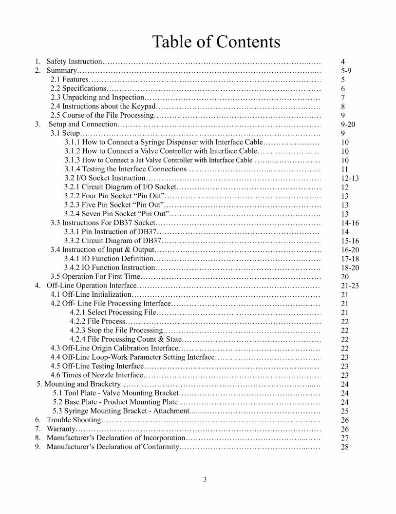
Table of Contents 1. Safety Instruction……………………………………………………………………..…….
2. Summary………………………………………………………………………………..…..
2.1 Features………………………………………………………………………………
2.2 Specifications…………………………………………………………………………
2.3 Unpacking and Inspection………………………………………………………………………….
2.4 Instructions about the Keypad………………………………………………….…….
2.5 Course of the File Processing…………………………………………………….………
3. Setup and Connection………………………………………………………………………
3.1 Setup…………………………………………………………………………………
3.1.1 How to Connect a Syringe Dispenser with Interface Cable…………………….
3.1.2 How to Connect a Valve Controller with Interface Cable……………………
3.1.3 How to Connect a Jet Valve Controller with Interface Cable ……..…………………
3.1.4 Testing the Interface Connections …………………………..………………..
3.2 I/O Socket Instruction…………………………………………………………………
3.2.1 Circuit Diagram of I/O Socket…………………………………………………
3.2.2 Four Pin Socket “Pin Out”……………………………….………………….…
3.2.3 Five Pin Socket “Pin Out”…………………………………………………….
3.2.4 Seven Pin Socket “Pin Out”……………………….…………………………..
3.3 Instructions For DB37 Socket…………………………………………………………
3.3.1 Pin Instruction of DB37……………………………………………………….
3.3.2 Circuit Diagram of DB37………………………………………………………
3.4 Instruction of Input & Output………….…………………………………………….
3.4.1 IO Function Definition………………………………………………….………
3.4.2 IO Function Instruction………………………………………………………….
3.5 Operation For First Time………………………………………………………………..
4. Off-Line Operation Interface………………………………………………………….…….
4.1 Off-Line Initialization…………………………………………………………………
4.2 Off- Line File Processing Interface…………………………………………….……..
4.2.1 Select Processing File……………………………………………………………
4.2.2 File Process……………………………………………………………….……..
4.2.3 Stop the File Processing………………………………………………………
4.2.4 File Processing Count & State…………………………………………………..
4.3 Off-Line Origin Calibration Interface…………………………………………….…..
4.4 Off-Line Loop-Work Parameter Setting Interface…………………………………....
4.5 Off-Line Testing Interface…………………………………………………….………..
4.6 Times of Nozzle Interface………………………………………………………………
5. Mounting and Bracketry………………………………………………………………...….….
5.1 Tool Plate - Valve Mounting Bracket……………………………………….…………..
5.2 Base Plate - Product Mounting Plate…………………………………………………….
5.3 Syringe Mounting Bracket - Attachment.........………………………………………
6. Trouble Shooting…………………………………………………………………….…….
7. Warranty……………………………………………………………………………………..
8. Manufacturer’s Declaration of Incorporation………………………………………...……………
9. Manufacturer’s Declaration of Conformity…………………………………………..………….
4
5-9
5
6
7
8
9
9-20
9
10
10
10
11
12-13
12
13
13
13
14-16
14
15-16
16-20
17-18
18-20
20
21-23
21
21
21
22
22
22
22
23
23
23
24
24
24
25
26
26
27
28
4
1. SAFETY INSTRUCTION
Caution about the main unit
Only use this robot with correct rated voltage and frequency (refer to the markings on the back of equipment).
Do not move the XY moving plate and the top head, by hand. This will protect them from damage.
During processing, do not touch the moving parts.
Before use, check the heating controller and pressure reduction valve have been fastened reliably (if fitted).
Keep the unit dry. Do not use or disconnect the equipment with wet hands.
If an emergency event occurs, press the emergency switch (red) immediately. The main unit will cut off the
power and stop processing the dispensing file.
Caution about the power cord
This machine is equipped with a 3-wire grounding plug and must be plugged into a 3-terminal grounded socket.
Do not modify the plug or use an ungrounded power socket. If an extension cord is necessary, use only a 3-wire
extension cord that provides grounding.
Do not turn on the power of the machine if any parts are damaged, especially if the power cord is damaged.
Caution about the teaching pendant
Do not connect the teaching pendant during a profile. When disconnecting the teaching pendant, loosen and
remove the fixing screws and then pull out it, once the profile has finished.
For protecting the teaching pendant, from damage, do not drop it on the floor or shake it intensively.
Caution about the air supply
Ensure the air flow is dry and clean. Select a suitable air pressure according the application. Suggested air
pressure is no more than 100 psi (6.9bar).
During use, do not over bend or over rotate the air tubes.
5
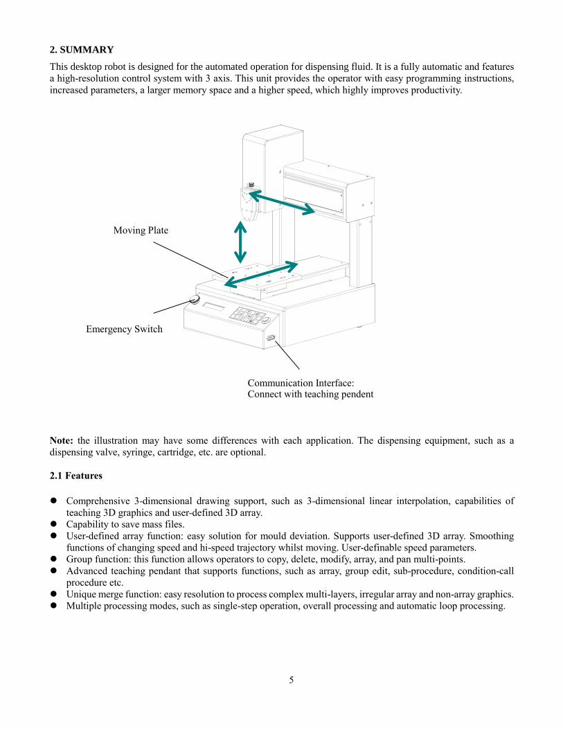
2. SUMMARY
This desktop robot is designed for the automated operation for dispensing fluid. It is a fully automatic and features
a high-resolution control system with 3 axis. This unit provides the operator with easy programming instructions,
increased parameters, a larger memory space and a higher speed, which highly improves productivity.
Note: the illustration may have some differences with each application. The dispensing equipment, such as a
dispensing valve, syringe, cartridge, etc. are optional.
2.1 Features
Comprehensive 3-dimensional drawing support, such as 3-dimensional linear interpolation, capabilities of
teaching 3D graphics and user-defined 3D array.
Capability to save mass files.
User-defined array function: easy solution for mould deviation. Supports user-defined 3D array. Smoothing
functions of changing speed and hi-speed trajectory whilst moving. User-definable speed parameters.
Group function: this function allows operators to copy, delete, modify, array, and pan multi-points.
Advanced teaching pendant that supports functions, such as array, group edit, sub-procedure, condition-call
procedure etc.
Unique merge function: easy resolution to process complex multi-layers, irregular array and non-array graphics.
Multiple processing modes, such as single-step operation, overall processing and automatic loop processing.
Moving Plate
Emergency Switch
Communication Interface: Connect with teaching pendent
6
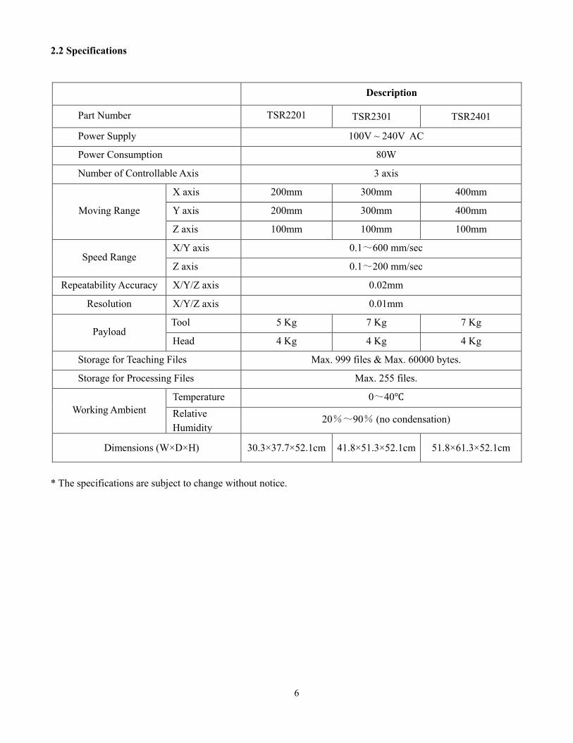
2.2 Specifications
Description
Part Number TSR2201 TSR2301 TSR2401
Power Supply 100V ~ 240V AC
Power Consumption 80W
Number of Controllable Axis 3 axis
Moving Range
X axis 200mm 300mm 400mm
Y axis 200mm 300mm 400mm
Z axis 100mm 100mm 100mm
Speed Range X/Y axis 0.1~600 mm/sec
Z axis 0.1~200 mm/sec
Repeatability Accuracy X/Y/Z axis 0.02mm
Resolution X/Y/Z axis 0.01mm
Payload Tool 5 Kg 7 Kg 7 Kg
Head 4 Kg 4 Kg 4 Kg
Storage for Teaching Files Max. 999 files & Max. 60000 bytes.
Storage for Processing Files Max. 255 files.
Working Ambient
Temperature 0~40℃
Relative
Humidity 20%~90% (no condensation)
Dimensions (W×D×H) 30.3×37.7×52.1cm 41.8×51.3×52.1cm 51.8×61.3×52.1cm
* The specifications are subject to change without notice.
7
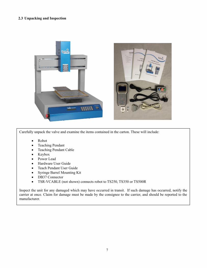
2.3 Unpacking and Inspection
Carefully unpack the valve and examine the items contained in the carton. These will include:
Robot
Teaching Pendant
Teaching Pendant Cable
Keybox
Power Lead
Hardware User Guide
Teach Pendant User Guide
Syringe Barrel Mounting Kit
DB37 Connector
TSR-VCABLE (not shown) connects robot to TS250, TS350 or TS500R
Inspect the unit for any damaged which may have occurred in transit. If such damage has occurred, notify the
carrier at once. Claim for damage must be made by the consignee to the carrier, and should be reported to the
manufacturer.
8
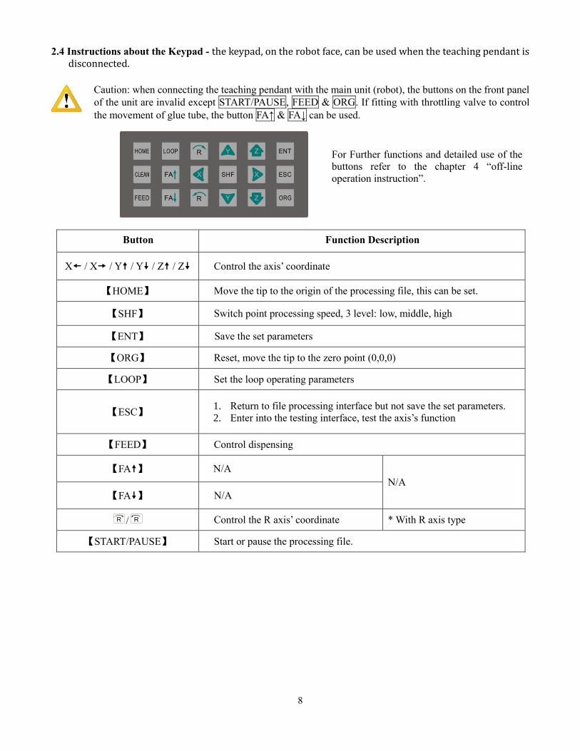
2.4 Instructions about the Keypad - the keypad, on the robot face, can be used when the teaching pendant is disconnected.
Caution: when connecting the teaching pendant with the main unit (robot), the buttons on the front panel
of the unit are invalid except START/PAUSE, FEED & ORG. If fitting with throttling valve to control
the movement of glue tube, the button FA↑ & FA↓ can be used.
Button Function Description
X / X / Y / Y / Z / Z Control the axis’ coordinate
【HOME】 Move the tip to the origin of the processing file, this can be set.
【SHF】 Switch point processing speed, 3 level: low, middle, high
【ENT】 Save the set parameters
【ORG】 Reset, move the tip to the zero point (0,0,0)
【LOOP】 Set the loop operating parameters
【ESC】 1. Return to file processing interface but not save the set parameters.
2. Enter into the testing interface, test the axis’s function
【FEED】 Control dispensing
【FA】 N/A
N/A
【FA】 N/A
R / R Control the R axis’ coordinate * With R axis type
【START/PAUSE】 Start or pause the processing file.
For Further functions and detailed use of the
buttons refer to the chapter 4 “off-line
operation instruction”.
9
2.5 Course of the File Processing
To complete a process file there needs to be three steps: program-adjust-process. For detailed operation refer to
the “operation manual of the teaching pendant”.
Program: The method of teaching a program.
Adjust: Adjusting the programming file, such as origin calibration, slant array, height adjusts, file
parameters adjust (including speed, acceleration, delay time, distance etc.)
Process: Download the program file to the system, from the teaching pendant.
The program is now complete and can be initiated.
3. SETUP AND CONNECTION
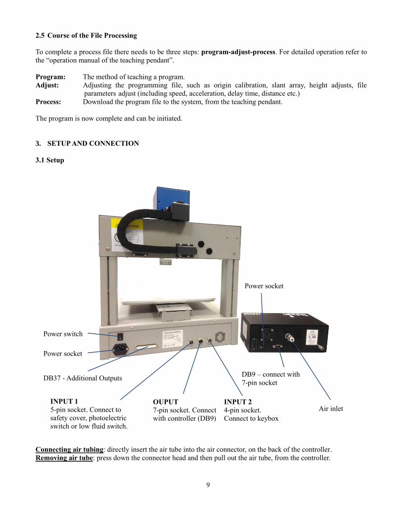
3.1 Setup
Connecting air tubing: directly insert the air tube into the air connector, on the back of the controller.
Removing air tube: press down the connector head and then pull out the air tube, from the controller.
DB9 – connect with
7-pin socket
Power switch
Power socket
INPUT 2
4-pin socket.
Connect to keybox
OUPUT
7-pin socket. Connect
with controller (DB9)
Air inlet
Power socket
DB37 - Additional Outputs
INPUT 1
5-pin socket. Connect to
safety cover, photoelectric
switch or low fluid switch.
10
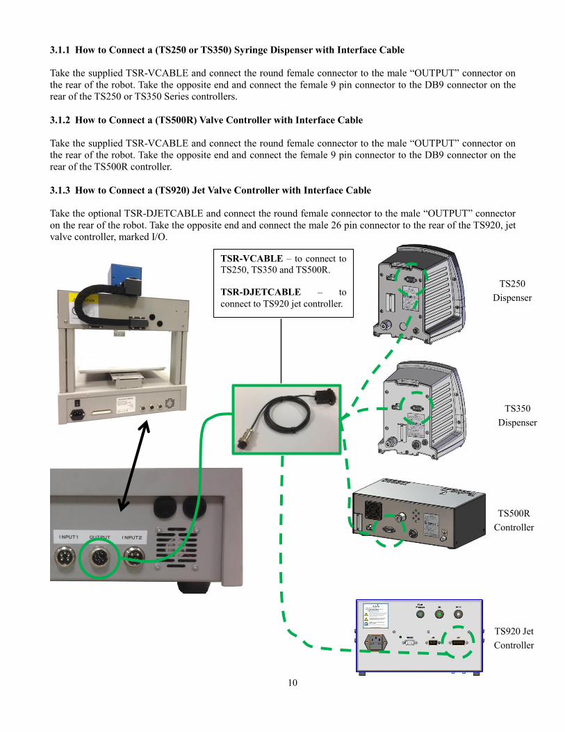
3.1.1 How to Connect a (TS250 or TS350) Syringe Dispenser with Interface Cable
Take the supplied TSR-VCABLE and connect the round female connector to the male “OUTPUT” connector on
the rear of the robot. Take the opposite end and connect the female 9 pin connector to the DB9 connector on the
rear of the TS250 or TS350 Series controllers.
3.1.2 How to Connect a (TS500R) Valve Controller with Interface Cable
Take the supplied TSR-VCABLE and connect the round female connector to the male “OUTPUT” connector on
the rear of the robot. Take the opposite end and connect the female 9 pin connector to the DB9 connector on the
rear of the TS500R controller.
3.1.3 How to Connect a (TS920) Jet Valve Controller with Interface Cable
Take the optional TSR-DJETCABLE and connect the round female connector to the male “OUTPUT” connector
on the rear of the robot. Take the opposite end and connect the male 26 pin connector to the rear of the TS920, jet
valve controller, marked I/O.
444
TS920 Jet
Controller
TS500R
Controller
TS350
Dispenser
TS250
Dispenser
TSR-VCABLE – to connect to
TS250, TS350 and TS500R.
TSR-DJETCABLE – to
connect to TS920 jet controller.
11
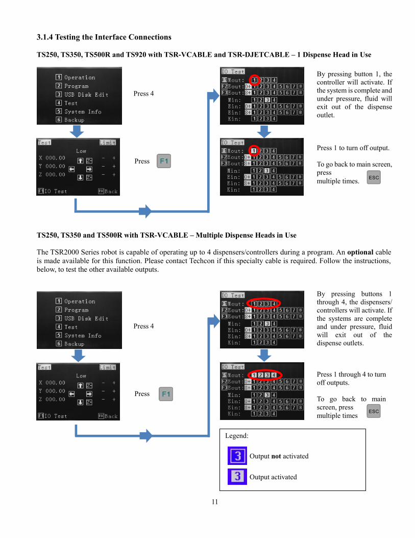
3.1.4 Testing the Interface Connections
TS250, TS350, TS500R and TS920 with TSR-VCABLE and TSR-DJETCABLE – 1 Dispense Head in Use
TS250, TS350 and TS500R with TSR-VCABLE – Multiple Dispense Heads in Use
The TSR2000 Series robot is capable of operating up to 4 dispensers/controllers during a program. An optional cable
is made available for this function. Please contact Techcon if this specialty cable is required. Follow the instructions,
below, to test the other available outputs.
Press 4
Press
Press 4
Press
By pressing button 1, the
controller will activate. If
the system is complete and
under pressure, fluid will
exit out of the dispense
outlet.
Press 1 to turn off output.
To go back to main screen,
press
multiple times.
Press 1 through 4 to turn
off outputs.
To go back to main
screen, press
multiple times
By pressing buttons 1
through 4, the dispensers/
controllers will activate. If
the systems are complete
and under pressure, fluid
will exit out of the
dispense outlets.
Legend:
Output not activated
Output activated
12
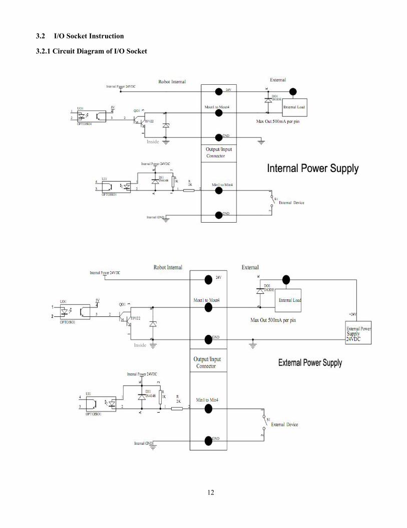
3.2 I/O Socket Instruction
3.2.1 Circuit Diagram of I/O Socket
Inside
Inside
13
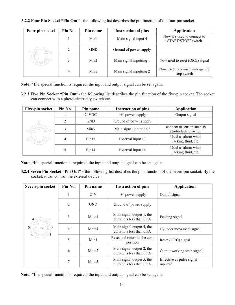
3.2.2 Four Pin Socket “Pin Out” - the following list describes the pin function of the four-pin socket.
Four-pin socket Pin No. Pin name Instruction of pins Application
1 Min4 Main signal input 4 Now it’s used to connect to
“START/STOP” switch.
2 GND Ground of power supply
3 Min1 Main signal inputting 1 Now used to reset (ORG) signal
4 Min2 Main signal inputting 2 Now used to connect emergency
stop switch
Note: *If a special function is required, the input and output signal can be set again.
3.2.3 Five Pin Socket “Pin Out”- the following list describes the pin function of the five-pin socket. The socket
can connect with a photo-electricity switch etc.
Five-pin socket Pin No. Pin name Instruction of pins Application
1 24VDC “+” power supply Output signal
2 GND Ground of power supply
3 Min3 Main signal inputting 3 connect to sensor, such as
photoelectric switch
4 Ein13 External input 13 Used as alarm when
lacking fluid, etc.
5 Ein14 External input 14 Used as alarm when
lacking fluid, etc.
Note: *If a special function is required, the input and output signal can be set again.
3.2.4 Seven Pin Socket “Pin Out” - the following list describes the pins function of the seven-pin socket. By the
socket, it can control the external device.
Seven-pin socket Pin No. Pin name Instruction of pins Application
1
2
34
5
6
7
1 24V “+” power supply Output signal
2 GND Ground of power supply
3 Mout1 Main signal output 1, the
current is less than 0.5A Feeding signal
4 Mout4 Main signal output 4, the
current is less than 0.5A Cylinder movement signal
5 Min1 Reset and return to the zero
position Reset (ORG) signal
6 Mout2 Main signal output 2, the
current is less than 0.5A Output working state signal
7 Mout5 Main signal output 5, the
current is less than 0.5A
Effective as pulse signal
inputted
Note: *If a special function is required, the input and output signal can be set again.
14
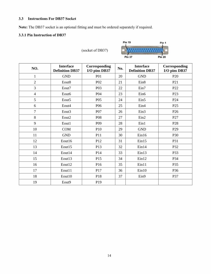
3.3 Instructions For DB37 Socket
Note: The DB37 socket is an optional fitting and must be ordered separately if required.
3.3.1 Pin Instruction of DB37
NO. Interface
Definition DB37
Corresponding
I/O pins DB37 No.
Interface
Definition DB37
Corresponding
I/O pins DB37
1 GND P01 20 GND P20
2 Eout8 P02 21 Ein8 P21
3 Eout7 P03 22 Ein7 P22
4 Eout6 P04 23 Ein6 P23
5 Eout5 P05 24 Ein5 P24
6 Eout4 P06 25 Ein4 P25
7 Eout3 P07 26 Ein3 P26
8 Eout2 P08 27 Ein2 P27
9 Eout1 P09 28 Ein1 P28
10 COM P10 29 GND P29
11 GND P11 30 Ein16 P30
12 Eout16 P12 31 Ein15 P31
13 Eout15 P13 32 Ein14 P32
14 Eout14 P14 33 Ein13 P33
15 Eout13 P15 34 Ein12 P34
16 Eout12 P16 35 Ein11 P35
17 Eout11 P17 36 Ein10 P36
18 Eout10 P18 37 Ein9 P37
19 Eout9 P19
(socket of DB37)
15
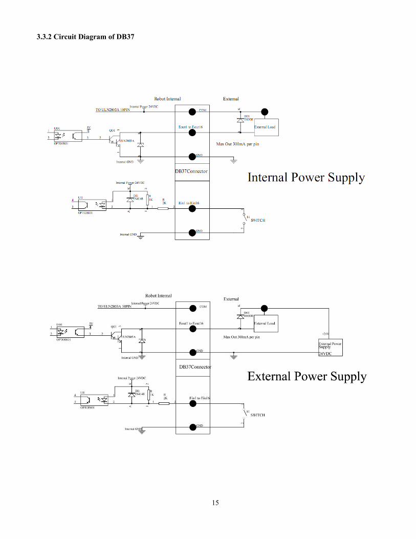
3.3.2 Circuit Diagram of DB37
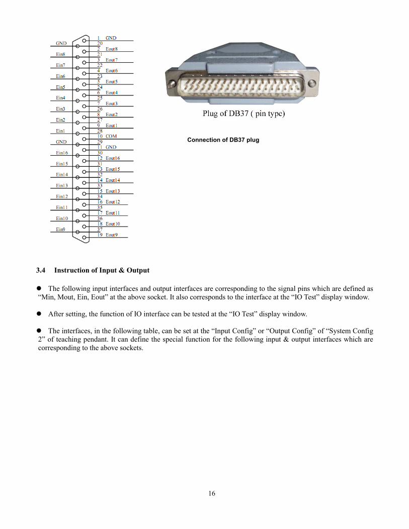
16
3.4 Instruction of Input & Output
The following input interfaces and output interfaces are corresponding to the signal pins which are defined as
“Min, Mout, Ein, Eout” at the above socket. It also corresponds to the interface at the “IO Test” display window.
After setting, the function of IO interface can be tested at the “IO Test” display window.
The interfaces, in the following table, can be set at the “Input Config” or “Output Config” of “System Config
2” of teaching pendant. It can define the special function for the following input & output interfaces which are
corresponding to the above sockets.
Connection of DB37 plug
17
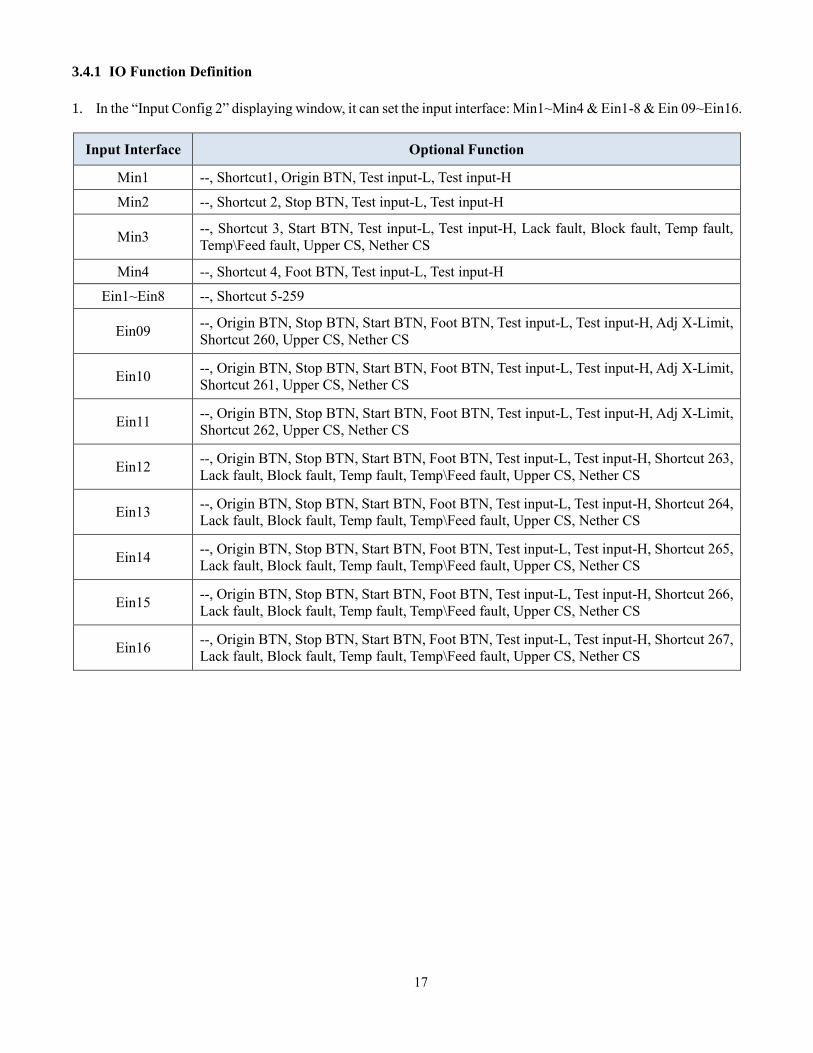
3.4.1 IO Function Definition
1. In the “Input Config 2” displaying window, it can set the input interface: Min1~Min4 & Ein1-8 & Ein 09~Ein16.
Input Interface Optional Function
Min1 --, Shortcut1, Origin BTN, Test input-L, Test input-H
Min2 --, Shortcut 2, Stop BTN, Test input-L, Test input-H
Min3 --, Shortcut 3, Start BTN, Test input-L, Test input-H, Lack fault, Block fault, Temp fault,
Temp\Feed fault, Upper CS, Nether CS
Min4 --, Shortcut 4, Foot BTN, Test input-L, Test input-H
Ein1~Ein8 --, Shortcut 5-259
Ein09 --, Origin BTN, Stop BTN, Start BTN, Foot BTN, Test input-L, Test input-H, Adj X-Limit,
Shortcut 260, Upper CS, Nether CS
Ein10 --, Origin BTN, Stop BTN, Start BTN, Foot BTN, Test input-L, Test input-H, Adj X-Limit,
Shortcut 261, Upper CS, Nether CS
Ein11 --, Origin BTN, Stop BTN, Start BTN, Foot BTN, Test input-L, Test input-H, Adj X-Limit,
Shortcut 262, Upper CS, Nether CS
Ein12 --, Origin BTN, Stop BTN, Start BTN, Foot BTN, Test input-L, Test input-H, Shortcut 263,
Lack fault, Block fault, Temp fault, Temp\Feed fault, Upper CS, Nether CS
Ein13 --, Origin BTN, Stop BTN, Start BTN, Foot BTN, Test input-L, Test input-H, Shortcut 264,
Lack fault, Block fault, Temp fault, Temp\Feed fault, Upper CS, Nether CS
Ein14 --, Origin BTN, Stop BTN, Start BTN, Foot BTN, Test input-L, Test input-H, Shortcut 265,
Lack fault, Block fault, Temp fault, Temp\Feed fault, Upper CS, Nether CS
Ein15 --, Origin BTN, Stop BTN, Start BTN, Foot BTN, Test input-L, Test input-H, Shortcut 266,
Lack fault, Block fault, Temp fault, Temp\Feed fault, Upper CS, Nether CS
Ein16 --, Origin BTN, Stop BTN, Start BTN, Foot BTN, Test input-L, Test input-H, Shortcut 267,
Lack fault, Block fault, Temp fault, Temp\Feed fault, Upper CS, Nether CS
18
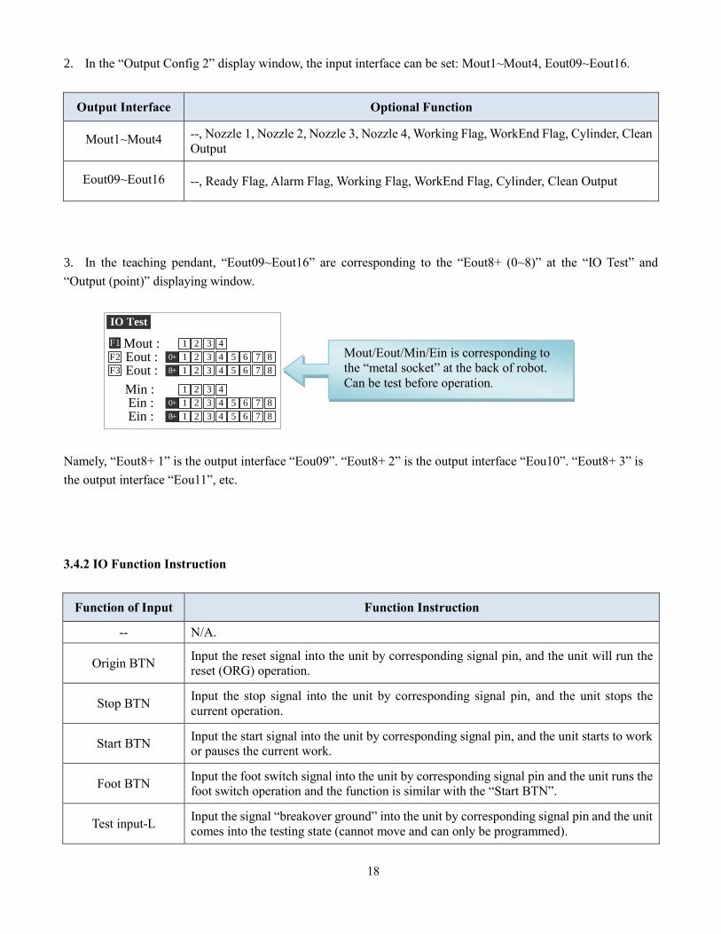
2. In the “Output Config 2” display window, the input interface can be set: Mout1~Mout4, Eout09~Eout16.
Output Interface Optional Function
Mout1~Mout4 --, Nozzle 1, Nozzle 2, Nozzle 3, Nozzle 4, Working Flag, WorkEnd Flag, Cylinder, Clean
Output
Eout09~Eout16 --, Ready Flag, Alarm Flag, Working Flag, WorkEnd Flag, Cylinder, Clean Output
3. In the teaching pendant, “Eout09~Eout16” are corresponding to the “Eout8+ (0~8)” at the “IO Test” and
“Output (point)” displaying window.
IO Test
Mout :F1 32 41
0+ 32 41 76 85
32 4 76 85
32 4 76 85
32 41
8+ 1
Eout :F2
Eout :F3
Min :Ein :
32 4 76 85Ein :0+
8+
1
1
Namely, “Eout8+ 1” is the output interface “Eou09”. “Eout8+ 2” is the output interface “Eou10”. “Eout8+ 3” is
the output interface “Eou11”, etc.
3.4.2 IO Function Instruction
Function of Input Function Instruction
-- N/A.
Origin BTN Input the reset signal into the unit by corresponding signal pin, and the unit will run the
reset (ORG) operation.
Stop BTN Input the stop signal into the unit by corresponding signal pin, and the unit stops the
current operation.
Start BTN Input the start signal into the unit by corresponding signal pin, and the unit starts to work
or pauses the current work.
Foot BTN Input the foot switch signal into the unit by corresponding signal pin and the unit runs the
foot switch operation and the function is similar with the “Start BTN”.
Test input-L Input the signal “breakover ground” into the unit by corresponding signal pin and the unit
comes into the testing state (cannot move and can only be programmed).
Mout/Eout/Min/Ein is corresponding to
the “metal socket” at the back of robot.
Can be test before operation.
19
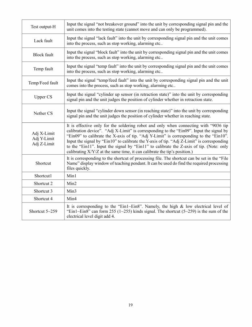
Test output-H Input the signal “not breakover ground” into the unit by corresponding signal pin and the
unit comes into the testing state (cannot move and can only be programmed).
Lack fault Input the signal “lack fault” into the unit by corresponding signal pin and the unit comes
into the process, such as stop working, alarming etc..
Block fault Input the signal “block fault” into the unit by corresponding signal pin and the unit comes
into the process, such as stop working, alarming etc..
Temp fault Input the signal “temp fault” into the unit by corresponding signal pin and the unit comes
into the process, such as stop working, alarming etc..
Temp/Feed fault Input the signal “temp/feed fault” into the unit by corresponding signal pin and the unit
comes into the process, such as stop working, alarming etc..
Upper CS Input the signal “cylinder up sensor (in retraction state)” into the unit by corresponding
signal pin and the unit judges the position of cylinder whether in retraction state.
Nether CS Input the signal “cylinder down sensor (in reaching state)” into the unit by corresponding
signal pin and the unit judges the position of cylinder whether in reaching state.
Adj X-Limit
Adj Y-Limit
Adj Z-Limit
It is effective only for the soldering robot and only when connecting with “9036 tip
calibration device”. “Adj X-Limit” is corresponding to the “Ein09”. Input the signal by
“Ein09” to calibrate the X-axis of tip. “Adj Y-Limit” is corresponding to the “Ein10”.
Input the signal by “Ein10” to calibrate the Y-axis of tip. “Adj Z-Limit” is corresponding
to the “Ein11”. Input the signal by “Ein11” to calibrate the Z-axis of tip. (Note: only
calibrating X/Y/Z at the same time, it can calibrate the tip’s position.)
Shortcut It is corresponding to the shortcut of processing file. The shortcut can be set in the “File Name” display window of teaching pendant. It can be used do find the required processing files quickly.
Shortcut1 Min1
Shortcut 2 Min2
Shortcut 3 Min3
Shortcut 4 Min4
Shortcut 5~259 It is corresponding to the “Ein1~Ein8”. Namely, the high & low electrical level of “Ein1~Ein8” can form 255 (1~255) kinds signal. The shortcut (5~259) is the sum of the electrical level digit add 4.
20
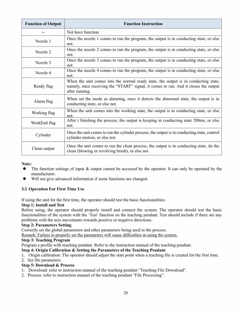
Function of Output Function Instruction
-- Not have function.
Nozzle 1 Once the nozzle 1 comes to run the program, the output is in conducting state, or else
not.
Nozzle 2 Once the nozzle 2 comes to run the program, the output is in conducting state, or else
not.
Nozzle 3 Once the nozzle 3 comes to run the program, the output is in conducting state, or else
not.
Nozzle 4 Once the nozzle 4 comes to run the program, the output is in conducting state, or else
not.
Ready flag
When the unit comes into the normal ready state, the output is in conducting state,
namely, once receiving the “START” signal, it comes to run. And it closes the output
after running.
Alarm flag When set the mode as alarming, once it detects the abnormal state, the output is in
conducting state, or else not.
Working flag When the unit comes into the working state, the output is in conducting state, or else
not.
WorkEnd flag After t finishing the process, the output is keeping in conducting state 200ms, or else
not.
Cylinder Once the unit comes to run the cylinder process, the output is in conducting state, control
cylinder motion, or else not.
Clean output Once the unit comes to run the clean process, the output is in conducting state, do the
clean (blowing or revolving brush), or else not.
Note:
The function settings of input & output cannot be accessed by the operator. It can only be operated by the
manufacturer.
Will not give advanced information if some functions are changed.
3.5 Operation For First Time Use
If using the unit for the first time, the operator should test the basic functionalities.
Step 1: Install and Test Before using, the operator should properly install and connect the system. The operator should test the basic
functionalities of the system with the ‘Test’ function on the teaching pendant. Test should include if there are any
problems with the axis movements towards positive or negative directions.
Step 2: Parameters Setting
Correctly set the global parameters and other parameters being used in the process.
Remark: Failure to properly set the parameters will cause difficulties in using the system.
Step 3: Teaching Program
Program a profile with teaching pendant. Refer to the instruction manual of the teaching pendant.
Step 4: Origin Calibration & Setting the Parameters of the Teaching Pendant
1. Origin calibration: The operator should adjust the start point when a teaching file is created for the first time.
2. Set file parameters.
Step 5: Download & Process
1. Download: refer to instruction manual of the teaching pendant “Teaching File Download”.
2. Process: refer to instruction manual of the teaching pendant “File Processing”.
21
4. OFF-LINE OPERATION INTERFACE
Caution: when connecting the teaching pendant with the main unit, the buttons on the front panel of the
unit are invalid except START/PAUSE, FEED & ORG.
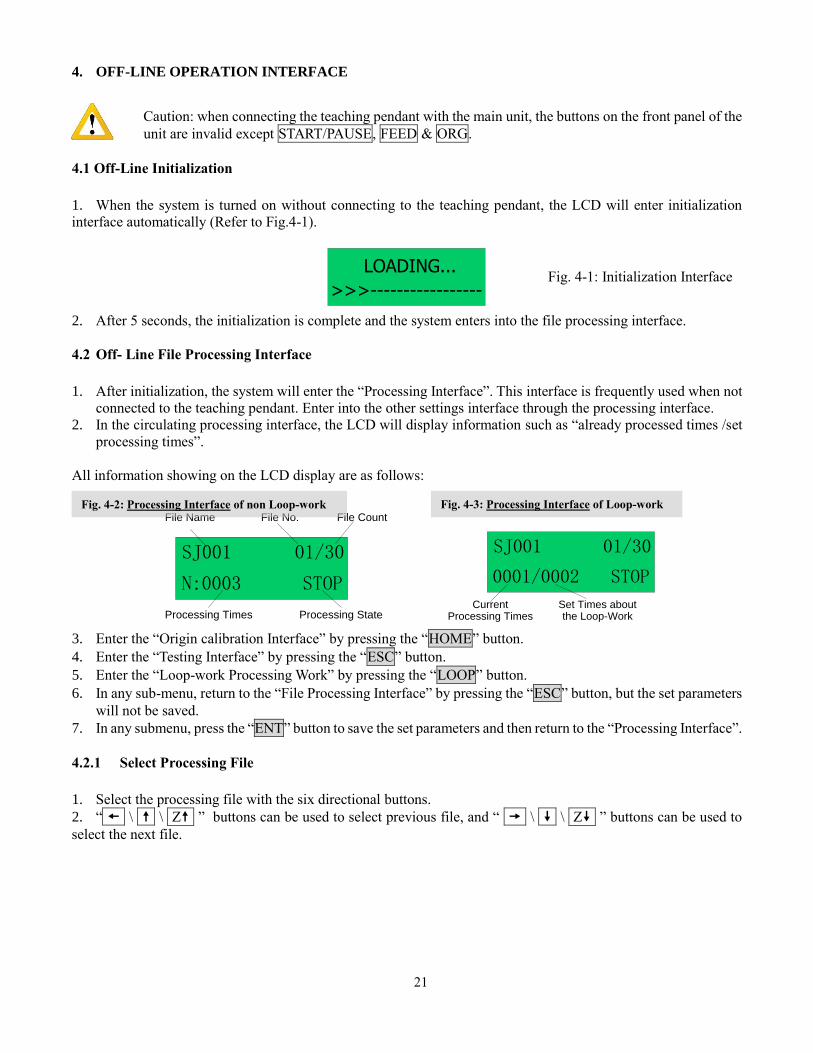
4.1 Off-Line Initialization
1. When the system is turned on without connecting to the teaching pendant, the LCD will enter initialization
interface automatically (Refer to Fig.4-1).
LOADING...
>>>-----------------
2. After 5 seconds, the initialization is complete and the system enters into the file processing interface.
4.2 Off- Line File Processing Interface
1. After initialization, the system will enter the “Processing Interface”. This interface is frequently used when not
connected to the teaching pendant. Enter into the other settings interface through the processing interface.
2. In the circulating processing interface, the LCD will display information such as “already processed times /set
processing times”.
All information showing on the LCD display are as follows:
SJ001
N:0003
01/30
STOP
File Name
Processing State
File No. File Count
Processing Times
SJ001
0001/0002
01/30
STOP
Set Times aboutthe Loop-Work
CurrentProcessing Times
3. Enter the “Origin calibration Interface” by pressing the “HOME” button.
4. Enter the “Testing Interface” by pressing the “ESC” button.
5. Enter the “Loop-work Processing Work” by pressing the “LOOP” button.
6. In any sub-menu, return to the “File Processing Interface” by pressing the “ESC” button, but the set parameters
will not be saved.
7. In any submenu, press the “ENT” button to save the set parameters and then return to the “Processing Interface”.
4.2.1 Select Processing File
1. Select the processing file with the six directional buttons.
2. “ \ \ Z ” buttons can be used to select previous file, and “ \ \ Z ” buttons can be used to
select the next file.
Fig. 4-2: Processing Interface of non Loop-work
Fig. 4-3: Processing Interface of Loop-work
Fig. 4-1: Initialization Interface
22
4.2.2 File Process
Press the “START/PAUSE” button to begin processing the selected file.
This button also can used to pause a file processing and then continue a file processing.
4.2.3 Stop the File Processing
Press “START/PAUSE” button or Emergency Switch to pause the processing file. START/PAUSE: only pauses
file processing, and the file state changes from “WORK” to “PAUSE”. If pressed again, the system will continue
the paused processing file and the file state changes to “WORK”.
Emergency Switch: Stops file processing and cuts off the power supply of the driver, the LCD displays
“EMERGENCY STOP PLEASE RESET”. Turn the emergency switch clockwise to reset.
Press the “ORG” button to make the tip return to the zero point. After that, the emergency
switch can be run again.
4.2.4 File Processing Count And State
1. At the lower left corner of processing interface the processing times are displayed. Press “SHF” button to clear
the digit to 0.
2. At the lower right corner of processing interface, the file processing state is displayed. The processing state is
changing with the processing course. The file processing state shown in the table below:
Table 4-1: File Processing State
Work State Remark
RESET The system is resetting.
STOP The process has been stopped.
WORK Processing.
PAUSE The process has been paused.
WAIT Waiting time for hanging a work-piece during the loop-work process.
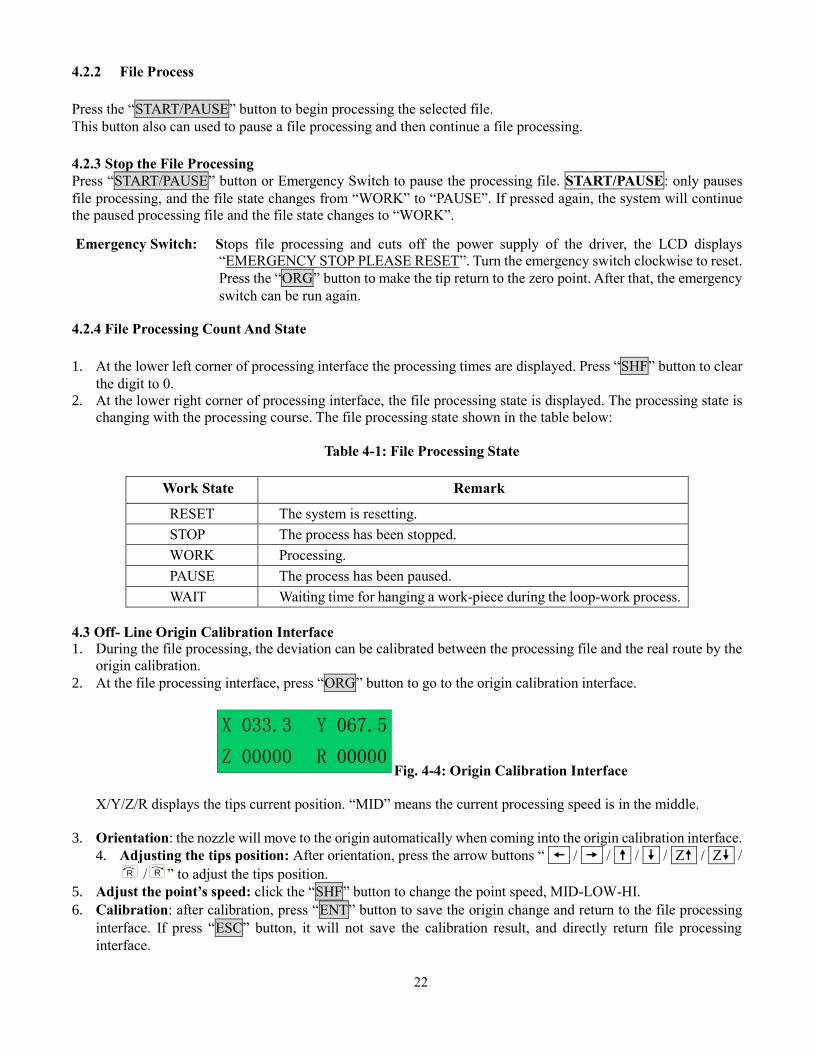
4.3 Off- Line Origin Calibration Interface
1. During the file processing, the deviation can be calibrated between the processing file and the real route by the
origin calibration.
2. At the file processing interface, press “ORG” button to go to the origin calibration interface.
X 033.3
Z 00000
Y 067.5
R 00000Fig. 4-4: Origin Calibration Interface
X/Y/Z/R displays the tips current position. “MID” means the current processing speed is in the middle.
3. Orientation: the nozzle will move to the origin automatically when coming into the origin calibration interface.
4. Adjusting the tips position: After orientation, press the arrow buttons “ / / / / Z / Z /R / R ” to adjust the tips position.
5. Adjust the point’s speed: click the “SHF” button to change the point speed, MID-LOW-HI.
6. Calibration: after calibration, press “ENT” button to save the origin change and return to the file processing
interface. If press “ESC” button, it will not save the calibration result, and directly return file processing
interface.
23
4.4 Off- Line Loop-Work Parameter Setting Interface
1. In the loop-work parameters setting, the unit can start the process without an operator at the location.
2. Press the “LOOP” button at the processing interface and then enter into the “loop–work parameter setting
interface”.
SJ001 N=0000
T=000.0s Rn=0000
Fig.4-5: Loop–work Parameter Setting Interface
3. When setting, select the digit by moving the cursor under the digit. The arrow buttons “ ” & “ ” can
move the cursor left and right and the arrow buttons “ ” & “ ” can move the cursor up and down.
4. After completing adjust, press the “ENT” button to save the parameters and return to the file processing
interface. When the “N=0000” or “N=0001” is displayed, without loop work processing and the file only
processes one time.
4.5 Off-Line Testing Interface
Press the ESC button to enter into the the testing interface. In the testing interface, common system functions can
be tested if they are running correctly or not. The operating interface is as follows:
X 033.3
Z 00000
Y 067.5
R 00000
X 033.3
Z 08.2
Y 000.0
MID
Fig. 4-6: Testing Interface
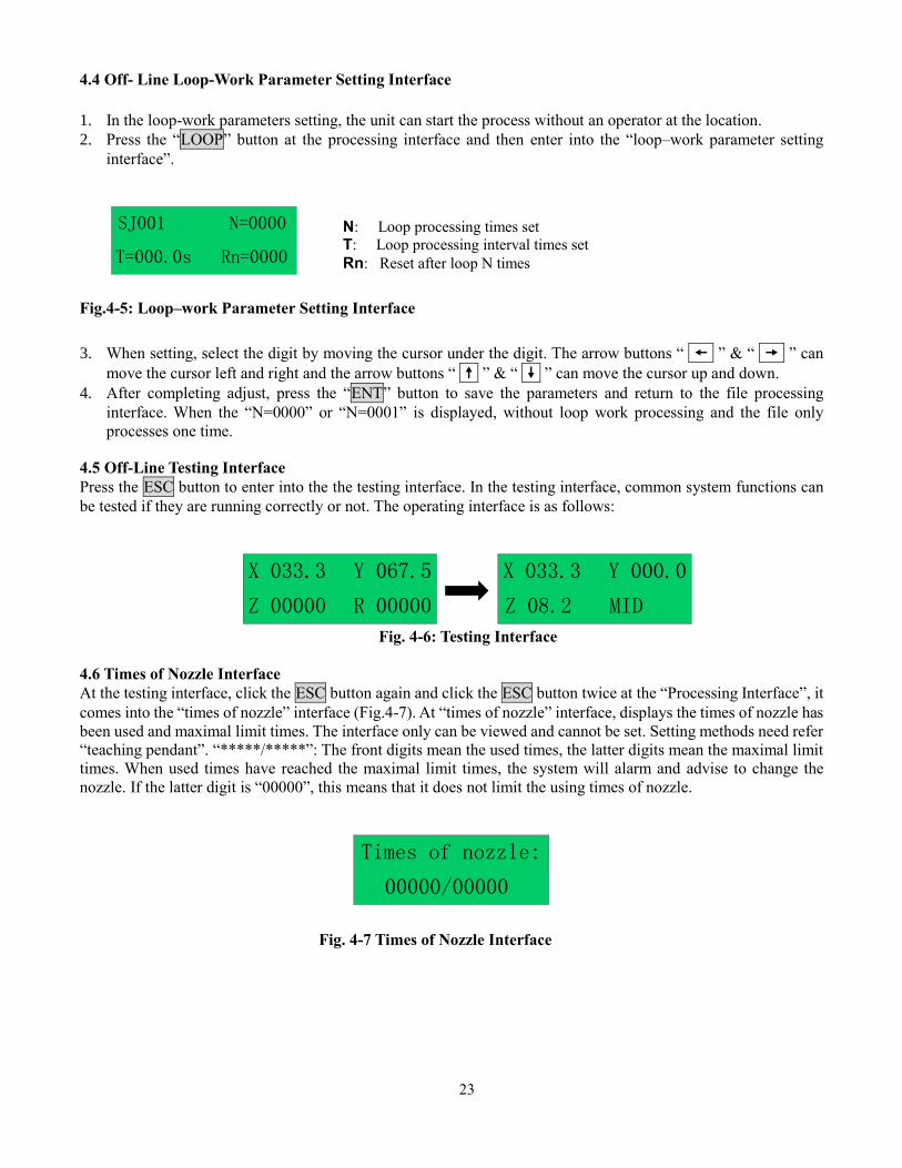
4.6 Times of Nozzle Interface
At the testing interface, click the ESC button again and click the ESC button twice at the “Processing Interface”, it
comes into the “times of nozzle” interface (Fig.4-7). At “times of nozzle” interface, displays the times of nozzle has
been used and maximal limit times. The interface only can be viewed and cannot be set. Setting methods need refer
“teaching pendant”. “*****/*****”: The front digits mean the used times, the latter digits mean the maximal limit
times. When used times have reached the maximal limit times, the system will alarm and advise to change the
nozzle. If the latter digit is “00000”, this means that it does not limit the using times of nozzle.
Times of nozzle:
00000/00000
Fig. 4-7 Times of Nozzle Interface
N: Loop processing times set
T: Loop processing interval times set
Rn: Reset after loop N times
24
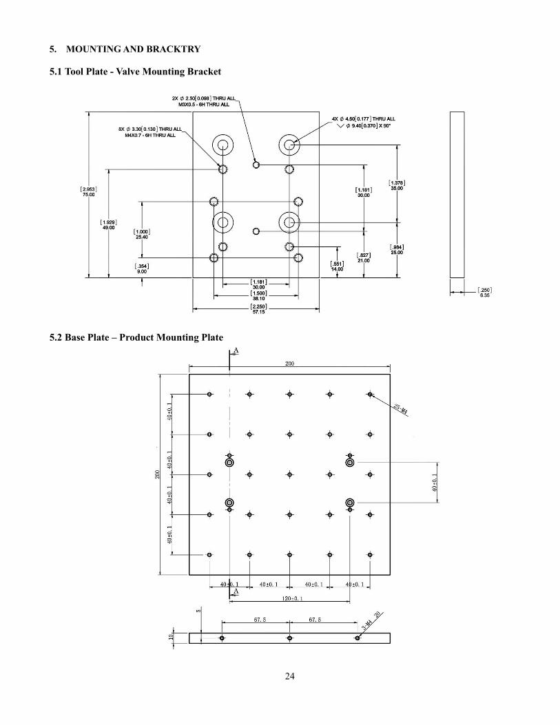
5. MOUNTING AND BRACKTRY
5.1 Tool Plate - Valve Mounting Bracket
5.2 Base Plate – Product Mounting Plate
25
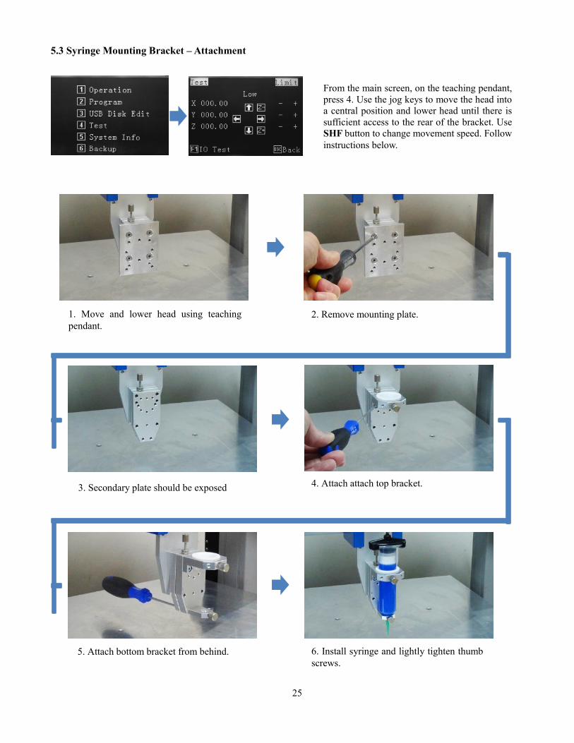
5.3 Syringe Mounting Bracket – Attachment
From the main screen, on the teaching pendant,
press 4. Use the jog keys to move the head into
a central position and lower head until there is
sufficient access to the rear of the bracket. Use
SHF button to change movement speed. Follow
instructions below.
1. Move and lower head using teaching
pendant.
2. Remove mounting plate.
4. Attach attach top bracket. 3. Secondary plate should be exposed
5. Attach bottom bracket from behind. 6. Install syringe and lightly tighten thumb
screws.
26
6. TROUBLE SHOOTING
1. The System cannot Reset after Booting.
Emergency switch error
Check the Emergency switch is not pressed, by mistake.
2. Z axis or X and Y axis cannot be Positioned Accurately in Processing
1) Loss of steps will cause inaccurate positioning phenomenon.
Overload, excessive speed or acceleration, insufficient power supply, or mismatched motor drive would lead to
the loss of steps. Please check the overload and the parameters settings. If the inaccurate positioning
phenomenon disappears or remits after reducing the speed or acceleration, we can make sure the phenomenon
is caused by the motor loss of steps. If inaccurate positioning phenomenon is very obvious for one axis, reduce
the acceleration of the axis.
2) Operation Error will cause inaccurate positioning phenomenon.
Do not reset when the work done
Make the system reset automatically after each accumulated processing error has been eliminated,)
7. WARRANTY
Manufacturer warrants this product to the original purchaser for a period of one (1) year from date of purchase to
be free from defects in material and workmanship, but not against damages by misuse, negligence, accident, faulty
installations and instructions. Manufacturer will repair or replace (at factory’s option), free of charge, any
component of the equipment thus found to be defective, on return of the component, “PREPAID” to the factory
during the warranty period. In no event shall any liability or obligation of the Manufacturer arising from this
warranty exceed the purchase price of the equipment. This warranty is only valid if the defective product is returned
as a complete assembly without physical damage. The Manufacturer’s liability, as stated herein, cannot be altered
or enlarged except by a written statement signed by an officer of the company. In no event shall the Manufacturer
be liable for consequential or incidental damages. A return authorization is required from Techcon Systems prior
to shipping a defective unit to the factory.
Manufacturer reserves the right to make engineering product modifications without notice.
All returns must be issued with a Returns Authorization number, prior to return. Send warranty returns to:
Techcon Systems Corporate Headquarters,
10800 Valley View Street, Cypress, 90630, USA.
Tel: 1-714-230-2398, Fax: 1-714-828-2001
E-mail: [email protected]
Techcon Systems European Corporate Office,
Eagle Close, Chandler’s Ford Industrial Estate,
Eastleigh, Hampshire, SO53 4NF, UK.
Tel: +44 2380 489 100, Fax: +44 2380 489 109
E-mail: [email protected]
27
8.
Manufacturer: Dover (Shenzhen) Industrial Equipment Manufacturing Co., Ltd
4 Floor West, 1 Building, Tingwei Industrial Park,
6 Liufang Road, Boa’an District,
Shenzhen, China
Manufacturer Contact: OK International Ltd.
Ian Jennings
Chandlers Ford, Hampshire Tel: +44 (0) 23 8048 9000
England SO53 4NF Fax: +44 (0) 23 8048 9109
Declares that the product(s): Industrial Robot/Bench-top Robot
Model Numbers: TSR2201, TSR2301, TSR2401
Option Kit Model Numbers:
TSR2200-SC
TSR2300-SC
TSR2400-SC
Is intended to be incorporated into machinery or to be assembled with other machinery to
constitute machinery covered by Directive 2006/42/EC.
And that the following harmonized standards and specifications have been used:
EN ISO 10218-1:2011
EN ISO 12100:2010
EN 60204-1/A1:2009
And furthermore declares that the product(s) covered by this Declaration must not be put into
service until the machinery into which it is to be incorporated or of which it is a component
has been found and declared to be in conformity with the provisions of directive 2006/42/EC.
Signature: Date: May 23rd, 2014
Jimmy Guo
Quality Engineer
Manufacturer’s Declaration of Incorporation
Directive: Machinery Directive 2006/42/EC
28
9.
This is to certify that models: TSR2201, TSR2301, TSR2401
Equipment Description: Industrial Robot/Bench-top Robot.
Supply Voltage: 100-240V AC, 50/60Hz.
Manufacturer Contact: OK International Ltd.
Ian Jennings
Chandlers Ford, Hampshire Tel: +44 (0) 23 8048 9000
England SO53 4NF Fax: +44 (0) 23 8048 9109
Effective Date: May, 23rd, 2014
Conforms to protection requirements of Council Directive 2004/108/EC, relating to
Electromagnetic Compatibility by the application of the following EMC Standards:
EN61000-6-2:2005
EN61000-6-4:A1/2011
I, the undersigned, hereby declare that the equipment specified above conforms to the above
Directive (s) and Standard (s).
Signature: Date: May 23rd, 2014
Jimmy Guo
Quality Engineer
Manufacturer’s Declaration of Conformity
Directive: EMC Directive 2004/108/EC


![Position Controller for Single-axis Robot/Cartesian Robot/ · PDF filePosition Controller for Single-axis Robot/Cartesian Robot/ ... [Function Comparison Table] ... * This product](https://img.pdfslide.us/doc/110x75/5aa9674c7f8b9a81188cbc2f/position-controller-for-single-axis-robotcartesian-robot-controller-for-single-axis.jpg)