Embed Size (px)
Citation preview

Full Paper
Finite element for dynamic analysis of a C-shape piezoelectric actuator
A.N.Mtawa*, W.MwitaMbeya Institute of Science and Technology, Mechanical Engineering Department P.O.Box-131, Mbeya, (TANZANIA)
E-mail : [email protected]; [email protected]: 9th September, 2010 ; Accepted: 19th September, 2010
An Indian JournalTrade Science Inc.
Volume 5 Issue 1
Nano Science and Nano TechnologyNano Science and Nano Technology
NSNTAIJ, 5(1), 2011 [1-12]
ISSN : 0974 - 7494
C-shape piezoelectricactuator;
Curved actuator;Piezocomposite actuator.
KEYWORDSABSTRACT
A Finite element model based on the Euler-Bernoulli theory was developedand used to investigate the dynamic behaviour of a C-shape piezoelectricactuator subjected to sinusoidal voltage. The main goal of this study wasto develop and validate numerical analysis tools for semicircular shapepiezoelectric devices. Once validated for a simple configuration the resultscan ultimately be extended for more complicated geometries and be helpfulin the optimization of the design of curved shape piezoelectric actuators.The dynamic solutions for a free and forced undamped piezoelectric actua-tor were obtained using a modal analysis method. For the verification offinite element formulation, a MATLAB code was developed to aid in thecomputation of the fundamental frequency and the corresponding normalmode of a four elements model. The results have been validated by com-paring them with published data. The general purpose Finite Element soft-ware MSC Marc was also used to simulate the first 3 natural frequenciesand their respective mode shapes as well as locating the resonance pointsfor three actuators from three different substrate materials and for threedifferent substrate/Piezoceramic thickness ratios. Results show that anincrease of both substrate to piezoceramic thickness ratio and the elasticmodulus of the substrate contributed to raise the fundamental frequencyof the actuator. It was also found that an actuator with mild steel substrateoperated at higher frequencies compared with the aluminium and brasssubstrates of the same thickness. 2011 Trade Science Inc. - INDIA
INTRODUCTION
Smart materials and structures
Smart structures, sometimes referred to as intelli-gent structures, are structures with extraordinary abili-ties. They are capable of self-correcting in order toimprove and enhance their performance.
A smart structure features a network of sensors and
actuators with real-time control capabilities and a hoststructure (Figure 1).
These sensors and actuators are made from smartmaterials. This is a group of materials that possess un-usual properties. They produce certain responses uponbeing subjected to certain types of external stimuli suchas electrical and magnetic fields, mechanical, chemicaland thermal energy. This group of materials includes:
id8878703 pdfMachine by Broadgun Software - a great PDF writer! - a great PDF creator! - http://www.pdfmachine.com http://www.broadgun.com

Finite element for dynamic analysis of a C-shape piezoelectric actuator2
Full PaperNSNTAIJ, 5(1) 2011
Nano Science and Nano Technology
An Indian Journal
Piezoelectric (PZT); Shape Memory Alloys (SMA),ElectroRheological (ER) and MagnetoRheologicaletc.[1,2].
Integration of smart materials in structures is amongthe most promising technologies for improved reliabil-ity of structures and systems. Understanding and con-trol of material properties, geometry and improved con-trol algorithms are among the ultimate objectives of re-search in this field.
The need and expectation of smart materials forengineering applications have increased enormously, andthe expectation of the technology to achieve them ispromising. The following are some of the expectations: High level of reliability, efficiency and sustainability
of structures and systems. High security of the infrastructures especially when
subjected to extreme and unstructured conditions-Hazard free structures.
Continuous health and integrity monitoring. Damage detection and self-recovery. Intelligent operational management system.
Application of smart structures
Examples of potential smart structural systems andsome mechanisms are air-craft (monitoring the state ofstrains in key locations and giving warning to preventdevelopment and propagation of cracks), buildings(earthquake damage resistance, smart windows, elec-tronic windows that sense weather changes and humanactivity and automatically adjust light and heat),bridges(monitoring of strains, deflections and vibrationcharacteristics in order to warn of impeding failures),ships (hulls and propulsion systems that detect and re-move turbulence and prevent deflection),machinery(tools chatter suppression, rotor critical speedcontrol), pipelines(monitoring of leakage and damagein underground pipes of water, oil and gas), medicaldevices (blood sugar sensors, insulin delivery pumps,
micro-motor capsules that unclog arteries, filters thatexpand after insertion into vessels to trap blood clots)[1].
Piezoelectric materials
Piezoelectric (PZT), as one of smart materials, un-dergo mechanical (dimensional or shape) change whensubjected to an electric field and vice versa (Figure 2a).This characteristic makes them to be suitable for fabri-cation of sensors and actuator applications. Energyconversion of piezoelectric devices mainly dependsupon the applied voltage, piezoelectric material prop-erties and the geometrical configuration of the actuatoror sensor device.
Improvement of actuator performance in terms ofdisplacement, force generation, reduced hysteresis, re-sponse time and bandwidth are among the most signifi-cant parameters to be studied.
Earlier PZT actuators were mainly used in staticoperations such as precision positioning or machine,adjustments, but recently PZT actuators are increas-ingly being demanded for more complicated operations.Dynamically actuated components such as valves andfuel injection devices, together with applications in adap-tive smart structures such as shape tuning, vibration ex-citation, cancellation, and mode shape tuning noise re-duction etc, are a few examples. For these operations,fast responses, large displacement and force are issuesof concern. In certain applications, particularly in vi-bration control, small actuators with minimum powerconsumption, large displacement and force capable ofoperating both at low and high frequencies are increas-ingly under demand[3-5].
Curved piezoelectric actuators
Different geometric configurations of piezoelectricsensors and actuators are in use today. Curved piezo-electric actuators are increasingly used nowadays in ap-plications such as vibration control, satellite control etc.
Control
Actuator Sensor
Data instruction Data acquisition
Control
Actuator Sensor
Data instruction Data acquisition
Figure 1 : Basic elements forming a smart structures
Mechanicalenergy
Piezoelectricmaterial
Electricalenergy
Displacement
Force
Electricalcharge
Electricalpotential
Mechanicalenergy
Piezoelectricmaterial
Electricalenergy
Displacement
Force
Electricalcharge
Electricalpotential
Figure 2a : Energy conversion by piezoelectric materials

A.N.Mtawa and W.Mwita 3
Full PaperNSNTAIJ, 5(1) 2011
Nano Science and Nano Technology
An Indian Journal
A Better understanding of their dynamic behaviourupon application of electric voltage can improve theirdesign and hence effective operation and control ofstructures[6-8].
There is a wealth of dynamic analysis models de-veloped by J. Moskalik and D. Brei[9] for the C shapeactuator configuration, but the focus of their work hasbeen on the analytical (exact) method. The analyticalapproach is very challenging and involves a huge amountof mathematical work particularly when complicatedboundary conditions are involved. The Finite ElementMethod (FEM) is a widely accepted and powerful toolfor analyzing complex structures[10,11]. Also The FiniteElement Method lends itself to programming.
The influence of substrate material and thepiezoceramic material on the performance of the C ac-tuator as well as the effect of the thickness ratios be-tween the substrate and piezoceramic layers of the ac-tuator under quasistatic condition have been well stud-ied by Mtawa et al.[14,15 ].
The main focus of this study is to develop a simplecomputation tool using Finite Element Method to beused to analyze the behavior of the curved shape ac-tuator under dynamic condition.
C-shape piezoelectric actuator
The C-shape piezoelectric actuator, which is a semi-circular (curved) shell, is an invention of A.J. Moskalikand Diann Brei in 1996[12]. When individual C-shapeactuators are combined in series and/or parallel it ispossible to generate displacement and force larger thana comparable straight bender. The force produced byan array of C- shape actuators is proportional to thenumber of individual C-shape actuator elements in a
parallel arrangement, while the resulting displacementequals the sum of displacements of individual blocks ina series arrangement[13].
A unimorph individual C- shape piezoelectric ac-tuator (Figure 2b) consists of three layers laminated to-gether to form a semicircular shell i.e. one active layer(piezoceramic) and passive layers (bonding and sub-strate). The piezoceramic (PZT) layer is pre-plated withelectrode layers on its inner and outer surfaces. Thepiezo-ceramic layer together with its electrode is bondedon the outer surface of the substrate. Epoxy is used asthe bonding material and a strong bond is created be-tween the piezo layer and the substrate. This ensuresthat all loads applied by the active layer are transmittedfully to the passive layer. With the unimorph actuator,when the piezoelectric layer expands/contracts in theradial direction the strain in the plane normal to the pol-ing direction (i.e. in the circumferential direction) un-dergoes a contraction/expansion.
Finite element formulation
Selection/determination of finite elements
The C-shape piezoelectric actuator is obviously acurved shape. For simplicity and for computationaleconomy, flat (straight arc) elements can be used toapproximate a curved structure[16,17]. A straight arc ele-ment is assumed to undergo both extensional and bend-ing deformations provided that the deformations aresmall. A straight arc element is obtained by superposingthe standard two degrees of freedom (d.o.f) bar ele-ment to account for axial displacement with the fourd.o.f. beam element to account for lateral and rota-tional displacements[18] (Figure 3a and 3b). This is partlywhat contributes to the originality of this paper.
In the present formulation the following assump-tions are applied: that the piezoelectric actuator layersare perfectly bonded together (thus continuous strainacross the bond is guaranteed, and also shear stressesin the interfaces are ignored. Material behaviour is lim-ited within the linear elastic range (small displacementsand strains). The C shape actuator is assumed to be athin structure/beam, the Euler- Bernoulli model wasconsidered for the finite element analysis of the struc-ture, that is, the effect of transverse shear forces is ne-glected, cross-sections remain plane and normal to thedeformed longitudinal (neutral) axis, the rotational de-
Figure 2b : Unimorph C-shape actuator

Finite element for dynamic analysis of a C-shape piezoelectric actuator4
Full PaperNSNTAIJ, 5(1) 2011
Nano Science and Nano Technology
An Indian Journal
formation is due to bending alone[19-23].
Kinematics
The model presented in this paper is based on theEuler-Bernoulli theory wherein a multilayered structureis reduced to kinematically equivalent single layer,thereby a 3D problem is reduced to an equivalent 1Dproblem[24,25]. Each element is bound with two nodes,it consist of the piezoelectric, bonding and substratelayers (Figure 4a and 4b), this means the laminate be-haves as a �single� layer with �special� properties.
Each node has three degrees of freedom, that isaxial, lateral and rotational displacements. The nodaldisplacements of the beam element in a local coordi-nate for an element are given by:() = {u
1 w
1
1 u
2 w
2
2}T (1)
where u1, w
1,
1 and u
2, w
2,
2 are the respective ap-proximate values of the tangential displacement, lateraldisplacement and rotation at node 1 and node 2 re-spectively.
The displacement vector {D} at any point alongthe beam at any time may be expressed in terms of thespatial interpolation functions [Ni] and their correspond-ing nodal degrees of freedom {
i} as follows:
{D(x,t}=[(N1(x)), (N
2(x)), (N
3(x)), (N
4(x)), (N
5(x)), (N
6(x))]{
i(t)}
If the characteristics of the chord may be repre-sented by the corresponding straight arch element withthe same cross-section properties as those of the arc,the assumed displacement field equation would be:u(x,t) = a
1(t) + a
2x(t) (2)
w(x,t) = a3(t) + a
4x(t) + a
5x2(t) + a
6x3(t) (3)
These equations can also be rewritten as:U(x,t) = N
1(x)u
1(t) + N
2(x)u
2(t) (4)
W(x,t) = N3(x)w
1(t) + N
4(x)
1(t) + N
5(x) w
2(t) + N
6(x)
2(t) (5)
Combining equations 4 and 5 we can write:
)t(
)t(w
)t(u
)t(
)t(w
)t(u
)x(Nw0
)x(Nw0
0
)x(Nu
)x(Nw0
)x(Nw0
0
)x(Nu
)t,x(D)t,x(w
)t,x(u
2
2
2
1
1
1
65
2
43
1
(6)
Actuator equations
The general linear piezoelectric actuator for the con-verse piezoelectric effect can be described in a stressform as follows[26]: = [Q]E {}-{}T {E}
= [Q]E ({}-[d]T {E}) (7)
where = Mechanical Strain, = Mechanical stress,d= piezoelectric coupling coefficients for strain- chargeform, QE = Elastic modulus at fixed electric field, e =piezoelectric coupling coefficients for stress-Chargeform, E = Applied electric field and {e} = [d][Q]NB. Superscript T implies matrix transpose.
Strain energy
The strain energy associated with the extension canbe given by:
v
Text dv}{}{
21
U (8)
From constitutive relationship we can write:
n
1p
1
0ppp
Tpext dxAQ
21
U (9)
where p = 1,2�n is the number of layers. A = the cross-section area. Q = Young�s modulus of elasticity
Figure 3a = Straight arc element subjected to both exten-sional and bending deformations
Figure 3b : Straight arc element assemblage used to model anarc

A.N.Mtawa and W.Mwita 5
Full PaperNSNTAIJ, 5(1) 2011
Nano Science and Nano Technology
An Indian Journal
Eq. (9) can also be written as:
dx)}t()]{x(B[AQ)}t({)]x(B[21
)t(U iuipp
n
1p
1
0
Ti
Tuiext
(10)
where:
x)x(N
]B[ iu represent a matrix giving rela-
tionship between extensional displacement and strain.The strain energy associated with the bending de-
formation can be given by:
dxIQ2
MU
n
1p
l
0 pp
2
ben
(11)
But from mechanics of materials, the bending mo-ment is given by
2
2
dx
wdQIM (12)
where Q and I are the Young�s modulus of the material
and the second moment of area of a cross section aboutthe neutral axis respectively.
Substituting equation 12 into equation 11 and aftersome rearrangement, the instantaneous strain energy dueto bending becomes:
dx)]t()][x(B[2
IQ)}t({)]x(B[
dxdx
)t(wd
2
IQ
dx
)t(wd)t(U
i2ppn
1p
Ti
1
0
Tw
22
n
1p
pp
T1
02
2
ben
(13)
But
x
)xNB i
w is the matrix describing the re-
lationship between lateral displacement and the bend-ing strain.
Strain energy related to piezoelectric induced straincan be calculated using the following equation:
ve
T1Tpe dv}{]Q[}{
21
U (14)
Substituting eq. (7) into eq. (14) we obtain:
1
0
231
2zppe
z31T
i
1
0
Tppe
iT
i
1
0
T1ppe
Vez
Tpe
1pe
T
zT
pepe
dxdEbtQ
dxEd)}t({)]x(B[btQ
dx)}t()]{x(B[)}t({)]x(B[btQ21
dvEdQQ
EdQ
21
U
(15)
The total strain energy for the actuator is now givenby the summation of bending, extension and inducedpiezoelectric strains:U = U
ext + U
ben + U
pe
1
0
231
2
zpT
1
0
T
pz31peT
dxdEQbtdx)t({)]x(B[
tbEdQ)t(k)t(21
U
(16)
where: [ke] = Stiffness matrix of an element in a local
coordinate system given by,
n
1i
l
0wipp
Twi
uippT
ui
e dx)x(BIQ)x(B
)x(BAQ)x(B]k[ (17)
The elemental stiffness in a global reference systembecomes:K
e = []T[k
e][] (18)
where = Transformation matrix given by,
100000
0qr000
0rq000
000100
0000qr
0000rq
ii
ii
ii
ii
(19)
where qi = cos
i and r
i = sin
i.
i is an angle defining
orientation of the ith element with respect to global co-
Figure 4a : Straight arc element
Figure 4b : The laminated beam (from bottom to top: sub-strate, bond and piezoceramic layer)

Finite element for dynamic analysis of a C-shape piezoelectric actuator6
Full PaperNSNTAIJ, 5(1) 2011
Nano Science and Nano Technology
An Indian Journal
ordinate system.
Kinetic energy
The kinetic energy of an element is given by:
dxt
)t,x(w
t
)t,x(uA
21
)t(Tn
1p
L
0
2
i
2
ipp
(20)
where p is the mass density per unit length of the pth
layer. Ap The cross section area of the pth layer.
Taking into consideration the assumption that thereis a perfect bond between the layers, it implies that allpoints on the actuator cross-section will move with thesame velocities in the respective directions. The kineticenergy of an element eq. (20) becomes:
}D{m}D{
dx)x(ND)x(N
)x(N)x(N
AD21
)t(T
..
..
eT
l
0wi
TT
wi
uiT
ui
pp
T
(21)
where, [me] =Is a local mass matrix of an element given
by,
n
1p
l
0
Tppe dxNNAm (22)
where N= shape functions (eq.6)Similarly, using transformation matrix (eq. 19), the
elemental global mass matrix becomes:[M
e] = []T[m
e][] (23)
The elemental mass and stiffness matrices are thencombined to obtain their respective global mass andstiffness matrices [M] and [k] of the entire structure(actuator) while the boundary conditions are imposed.
Ne
1ee
T MM (24a)
Ne
1ee
T KK (24b)
where Ne is the number of elements in the entire struc-
ture (actuator).
Equations of motion
Equations of motion that governs the dynamic re-sponse of the structure can be derived by requiring thework of external forces to be equal to the work of in-ternal, inertia and viscous damping forces for any smallmotion that satisfies both compatibility and essential
boundary conditions(admissibility)[17]. Assuming no ex-ternally applied mechanical load for a single elementthe equation of motion becomes[27-29].
ePDeK.D
eDC..D
eM (25)
where: Me and K
e are global mass and stiffness matri-
ces of an element respectively.
..D A vector of nodal accelerations
.D A vector of nodal velocitiesD = A vector of nodal displacementsC
D = A matrix containing viscous damping terms.
Pe = Piezoelectric load vector given by
1
0
Tz31pee dx]B[EdQbtP (26a)
Pe = Qbt
pe d
31 E(-1 0 a 1 0 �a)T
= {-F 0 M F 0 �M}T (26b)
Assuming pepe
12
tV
t
VVE
and v
1 = 0 then
F = Qbd31
V (27a)
M = aQbd31
V (27b)
F and M are the induced actuator force and bendingmoment respectively. a = Moment arm (a distance fromthe neutral axis to the midline of the piezoceramic layer).tpe
represent the thickness of the piezoceramic layer.If the continuity at the inter-element nodes is im-
posed then the induced piezoelectric force and momentsare assumed to be applied at the free end tip of thepiezoelectric layer. This is due to the fact that there willbe force cancellations at these nodes.
Eq. (25) represents the dynamic behaviour of anelement. If equations of motion of all elements are as-sembled and then followed by applying the appropriateboundary conditions it yields the equation of motion ofthe entire C-shape piezoelectric actuator.
Eq. (25) can be rewritten into the forced vibrationequation by assuming the displacements, forces, andactuator voltages are harmonic variables with differentfrequencies. If the right hand side is put equal to zerothe equation is then reduced to the eigenvalue problem.From which eigenvalues
i and the eigenvectors (u
i, w
i
and i) can be determined.
Frequency response analysis
Modal analysis method
The amplitude � frequency response problem can
A.N.Mtawa and W.Mwita 7
Full PaperNSNTAIJ, 5(1) 2011
Nano Science and Nano Technology
An Indian Journal
be solved using the modal analysis method. In thismethod the expansion theorem is used where the dis-placements of masses are expressed as a linear combi-nation of the normal modes of the system. Assumingthat the system response is governed by �m� modes of
vibration, a set of �m� uncoupled differential equations
of second order is obtained. A solution of theses equa-tions is equivalent to the solutions of equations of �m�single degrees of freedom[30].
The solution of equation 25 using modal analysisbecomes,
n
1ii
)i(n
)n(2
)2(1
)1( )t(qX)t(qX....)t(qX)t(qX)t(D
(28)
where X = X(1), X(2), �. X(n) is the normal mode matrix
and
)t(q
...
)t(q
)t(q
)t(q
3
2
1
are the time-dependent generalized
(modal) coordinates,The nodal acceleration in terms of generalized co-
ordinates becomes,
)t(qX)t(D....
(29)
Substituting eq. (29) into eq. (25) we obtain,
)t(P)t(.qXDC)t(qXK)t(
..qXM (30a)
Multiplying eq. (30a) by XT both sides,
)t(PXXCX)t(qXKXXMX T.)t(qD
TT..)t(q
T
)t(Q)t(qDC)t(qK)t(..qM
.(30b)
where: XMXM T = the generalized modal mass ma-
trix, XKXK T = the generalized modal stiffness ma-
trix, XD
CTXDC = the generalized modal damping
matrix.Q(t) = XT P(t) = the generalized forces
Writing 2iid 2C , where
i is a modal damping
factor, and if the modal vectors are normalized in sucha way that
)1(diagIjifor1
jifor0XMXM )i(T)i(
where I is the identity matrix, and
)(diagjifor
jifor0XKXK 2
i2i
)i(T)i(
where I is the eigenfrequency of the ith
mode, then eq.(7.29b) reduces to a set of decoupled equations ofmotion given by,
)t(Q)t(.q22)t(q2)t(q
..(31)
Eq. (31) is a non homogeneous differential equa-tion which ordinary methods can now be used to solvefor individual responses in the modal coordinate sys-tem.
The ith decoupled equation of motion will be,
)t(Q)t(.
iq2
ii2)t(
iq2
i)t(
iq ..
(32)
Modal solution
Eq. (32) has the same form as those describing thedynamic response of a damped single degree of free-dom harmonic oscillator whose complete solution isgiven by,
d)t(sin)t(e)(Q1
)0(qtsine1
)0(qitsin1
tcose)t(q
diii
t
0i
di
.
ditii
di
di5.02i
idi
tiii
(33)
i = 1,2, ��..n
where 2idi 1i is a damped frequency..
qi 0 and
i are constants (generalized displace-
ments and phase angles respectively) which must bedefined from the modal initial conditions.
2
ii
2
i
2i
ii
21
0Q0q
(34a)
2
i1
ii2
1tani(34b)
Finite element for dynamic analysis of a C-shape piezoelectric actuator8
Full PaperNSNTAIJ, 5(1) 2011
Nano Science and Nano Technology
An Indian Journal
For i = 1, 2, ��n, is the number of degrees of
freedomwhere = the driving frequency.
The modal solutions obtained from eq. (33) are thentransformed back to obtain the solutions in the physicalcoordinates by using relationship (29).
Eigenvalue problem
In order to solve the equation of motion (eq. 25)using the modal analysis method it is necessary first tosolve the eigenvalue problem.
The natural frequencies i and the respective modes
of vibration X(i) of the piezoelectric actuator are ob-tained from the nth order polynomial in 2
by using eq.(25) by assuming an undamped free vibration conditioni.e. all external mechanical and electric excitations areassumed to be zero. This yields an eigenvalue problemof the form:
det(-2M + K) = 0 (35)
The corresponding eigenvectors can be obtainedby applying the following equation,(-w2
iM + K)X(i) = 0, for i = 1, 2, ��n (36)
NUMERICAL EXAMPLES
Computation of eigen frequency with the aid ofMATLAB
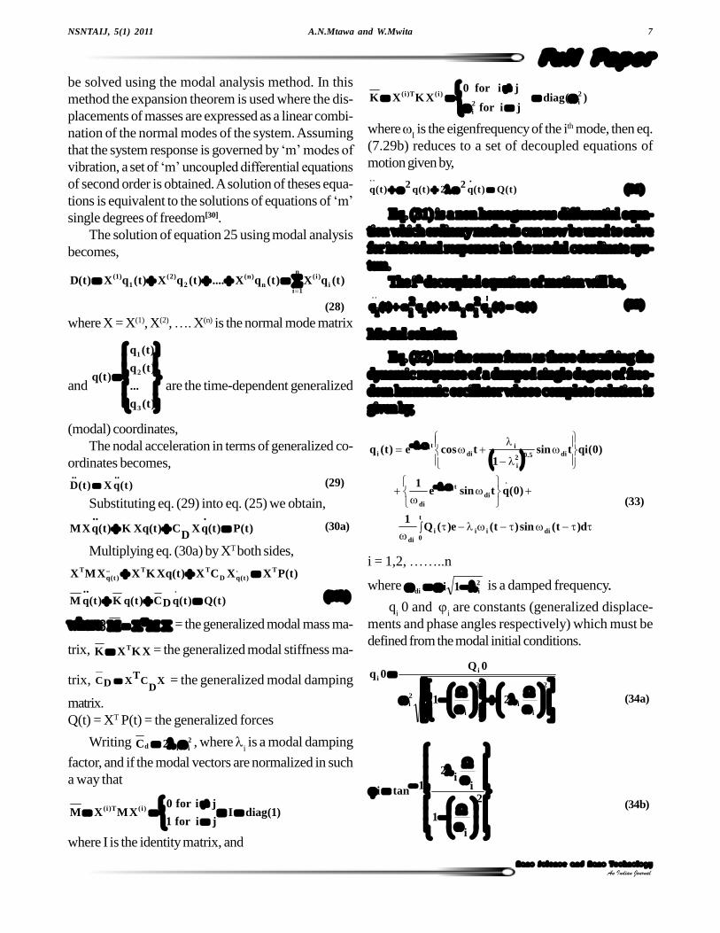
In order to verify the validity of the finite elementformulation the dynamic solution for a free/forced pi-ezoelectric actuator under sinusoidal excitation was ob-tained using the modal analysis method. The curvedactuator was approximated (divided) into 4 equal ele-ments (Figure 5). With the fixed-free boundary condi-tions, the local and global stiffness and mass matricesfor each element (eq. 17, 18, 22, 23) and later for thewhole structure (eq. 24a, 24b) were determined. Thematerial and geometrical characteristics of a C-shapepiezoelectric actuator used in the analysis are shown inTABLE 1.
The 3 lowest natural frequencies for the actuatorswith aluminium, brass and mild steel substrates each ofthree different thicknesses were computed with the aidof MATLAB code developed for this purpose. The re-sults were compared to those calculated using the ex-perimentally validated formula (eq. 37) obtained fromreference[9]. The results show good agreement as indi-cated in figure 6a-8a. An error of approximately 1.4%was noted. Their corresponding frequency-amplituderesponse curves are shown in figure 6b-8b.
TABLE 1 : Material properties and dimensions
Property and unit PZT26 Aluminium Brass Mild steel Epoxy
External radius[mm] 10 8.82 8.82 8.82 9.0
Thickness[mm] 1 0.25, 0.31, 0.5,1.0,2.0
0.25, 0.31, 0.5,1.0, 2.0
0.25, 0.31, 0.5,1.0, 2.0
0.18
Length[mm] 10 10 10 10 10
Piezoelectric strain coefficient d31 [m/v]
-1.3e-12 0 0 0 0
Elastic modulus2m
N 76e09 7.0e10 1.10e11 1.90e11 5.2e09
Density (kg/m3) 7.8e03 2.7e03 8.56e03 7.85e03 1.90e03
Maximum Voltage[VAC/mm]
200 - - - -
TABLE 2 : Electromechanical properties of the PZ6
Properties Value Unit E11s 1.30e-11
E12s -4.35e-12
E13s = E
23s -7.05e-12
E44s = E
55s 3.32e-11
E66s 3.47e-11
Nm 2
d31 -1.28e-10
d32 3.28e-10
d15 3.27e-10 N
C
r,11 1190
r,22 1190
r,33 1330
Relative value to vacuum permittivitymF
1085.8 12o
Figure 5 : C-shape piezoelectric actuator approximated withfour straight arc elements

A.N.Mtawa and W.Mwita 9
Full PaperNSNTAIJ, 5(1) 2011
Nano Science and Nano Technology
An Indian Journal
4na
2i2
i R
D(37)
where i = ith Natural frequency, D = Composite bending
stiffness[Nm2], i = ith
Non- dimensional natural fre-quency, = mass per length [kg/m] and R
na = Radius
of neutral axis[m]
Dynamic analysis simulation using MSC aarc
Overview
A dynamic modal analysis was performed to ob-tain the resonance modes of the actuator, and then aharmonic analysis was performed to determine the dy-namic response of the actuator to an alternating volt-age. Displacements at a range of frequencies aroundresonance points were determined. The dimensions andmaterial data for the models used in the simulation areas shown in TABLE 1 and 2.
Resonance points for the C-shape piezoelectric ac-tuator for 3 different substrate materials (i.e. Aluminium,Brass and Mild Steel) were determined. For each ma-terial three thicknesses (i.e. 0.25mm, 0.31mm, and0.5mm) were analysed.
Boundary conditions
One electrode was placed on one node on the in-ner surface of the piezoelectric ceramic to serve asground terminal, while another electrode was placedon one node at the outer surface of piezoelectric ce-ramic to serve the live terminal. In the model, these elec-trodes are made by tying the potential degree of free-dom of all nodes belonging to the respective surface toone node, that is all nodes on the inner surface are tiedup to the ground terminal while the outer surface nodesare tied up to the live terminal.
The left end tip was fixed while the right hand one
Figure 6b : Frequency - response curves for aluminium sub-strate at an excitation voltage of 10V, damping coefficient = 0.707
Figure 6a : Comparison of values of fundamental frequencyfor aluminium substrate
Figure7b : Frequency-response curves for brass substrate,(excitation voltage=10V, damping coefficient =0.7071)
Figure 7a : Comparison of values of fundamental frequencyfor brass substrate

Finite element for dynamic analysis of a C-shape piezoelectric actuator10
Full PaperNSNTAIJ, 5(1) 2011
Nano Science and Nano Technology
An Indian Journal
was left free to oscillate. Plane stress element type 160was used for the piezoelectric material. This element ismechanically equivalent to element 3 which was usedfor the substrate materials. This element type has threedegrees of freedom; the first two are for the X_ and Y_displacement, and the third is for the electric potential.
Modal analysis
Load cases and piezoelectric dynamic modal pa-rameters set to search for eigenfrequencies were as fol-lows:
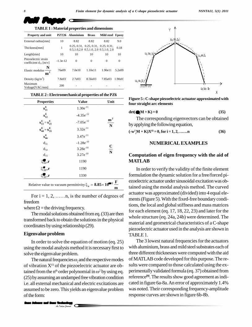
The LANCZOS method was used, whereas a num-ber of frequencies were set to 3. The frequencies ob-tained are shown in figure 9-11 (appendix B).
Harmonic analysis
For the harmonic analysis, the same model built formodal analysis was used. A new load case was set to suitharmonic boundary conditions. The frequency range was
Figure 8a : Comparison of values of fundamental frequencyfor mild steel substrate
selected to be around the first 2 natural frequencies, i.e.from 1 kHz and 5 kHz into 50 steps. Results obtainedare shown in figure 12 through 14(Appendix B).
Figure 12 for example, shows the X-displacementat frequencies 1053 Hz and 3276Hz which is close tothe first two resonant frequencies. The tip displacementmagnitude along the frequency range is plotted to showthe static solution (i.e. 0.676 Micrometer) at 0 Hz, andthe resonance around the first and second natural fre-quencies.
For both modal and harmonic analysis simulation a0.25mm substrate was used.
RESULTS AND DISCUSSION
Finite element models based on Euler Bernoullibeam theory were used to perform the dynamic analy-sis of C-shape actuator consisting of a three layerunimorph laminated beam (Piezoceramic layer, adhe-sive layer and metallic substrate) where the only defor-mation impetus was an actuation strain induced in thepiezoelectric layer.
The Effect of thickness and substrate material onthe displacement and on the operating bandwidth is asshown in figure 6b-8b for a 0.31mm substrates andfigure 12-14 (appendix B) for 0.25mm substrates. Theresults show that an increase of both substrate/PZTthickness ratio and the elastic modulus of the substratecontribute to raise the fundamental frequency of the C-shape actuator. This implies that with appropriate com-bination of the thickness ratio and the elastic propertiesof the actuator it can be possible to determine the loca-tion of the fundamental frequency and thus set the rangeover which the actuator can operate before reachingresonance frequency. From the results obtained it canalso be concluded that an actuator with a mild steelsubstrate can operate at higher frequencies comparedto aluminium and brass substrates of the same thick-ness.
It can also be noted that, in this study the C- actua-tor was approximated using one dimensional curvedactuator and more importantly only 4 finite elements(Straight arc) were used. The results reported in sec-tion 5.1 indicate that the predicted results and the re-sults calculated using eq. (37) from reference[9] give anerror of approximately 1.4%. This is apparent that if
Figure 8b : Frequency-response curves for a mild steel sub-strate (excitation voltage=10V, damping coefficient =0.7071)
A.N.Mtawa and W.Mwita 11
Full PaperNSNTAIJ, 5(1) 2011
Nano Science and Nano Technology
An Indian Journal
Figure 12 : the first two resonance points for a 0.25mm Alu-minium substrate (i.e. at 1053 and 3276 Hz respectively )
Figure 13 : The first two resonance points for a 0.25mm mildsteel substrate (i.e. at 1100and 3360 Hz respectively)
Figure 14 : The first two resonance points for a 0.25mm brasssubstrate
Figure 9 : First Mode shape for a 0.25mm Aluminium sub-strate
Figure 10 : Second Mode shape for a 0.25mm Aluminiumsubstrate
Figure 11 : The third mode shape for a 0.25mm Aluminiumsubstrate
the number of elements is increased much more accu-rate results could have been obtained. In view of this, itcan be concluded that the simplicity of the model canremarkably reduce the computational time.
ACKNOWLEDGEMENT
Authors wish to thank Prof. Bohua Sun, the Head

Finite element for dynamic analysis of a C-shape piezoelectric actuator12
Full PaperNSNTAIJ, 5(1) 2011
Nano Science and Nano Technology
An Indian Journal
of Smart Materials and Structures laboratory at CapePeninsula University of Technology- South Africa, forhis guidance, advice and for allowing most of the workto be done in the laboratory.
REFERENCES
[1] A.V.Srinivasan, D.McFarland, Michael; Cam-bridge: Cambridge University Press, �Smart Struc-
tures Analysis and Design�, (2001).[2] M.V.Andhi, B.S.Thomson; Michigan State Univer-
sity, �Smart Materials and Structures�, (1992).[3] Christopher Niezrecki, Diann Brei, Sivakumar
Balakrishanan, Andrew Moskalik; �Piezoelectric
Actuation�, State of the Art, The Shock and Vibra-
tion Digest, 33(4), 269-280 (2001).[4] N.J.Conway, Sang-Gook Kim; Technical Digest,
454-457 (2004).[5] E.V.Ardelean, D.G.Cole, R.L.Clark; Journal of In-
telligent Material Systems and Structures, 15, 879-889 (2004).
[6] El Mostafa Sekouri, Yan-Ru Hu, Anh Dung Ngo;Mechatronics, 14, 1007-1020 (2004).
[7] You-Di Kuang, Guo-Qing Li1, Chuan-Yao Chen;Smart Mater.Struct., 15, 869-876 (2006).
[8] J.M.Han, T.A.Adriaens, Willem L.de Koning,Reinder Banning; Modeling Piezoelectric Actua-tors IEEE/ASME Transactions on Mechatronics,5(4), 331 (2000).
[9] J.Moskalik, D.Brei; Journal of Sound and Vibra-tion, 243(2), 317-346 (2001).
[10] Young-Hun Lim, Vasundara V.Varadan, VijayK.Varadan; Smart Mater.Struct., 6, 161-168(1997).
[11] S.X.Xu, T.S.Koko; Finite Elements in Analysis andDesign, 40, 241-262 (2004).
[12] A.J.Moskalik, Diann Brei; Journal of IntelligentMaterial Systems and Structures, 3, 577-587(1997).
[13] A.J.Moskalik, Diann Brei; Smart Structure andMaterials, 8, 531-543 (1999).
[14] A.N.Mtawa, B.Sun, J.Gryzagoridis; Journal ofSmart Materials and Structures, 16, 1036-1042(2007).
[15] A.N.Mtawa, B.Sun, J.Gryzagoridis; Journal ofSensors and Actuators A, 141, 173-181 (2008).
[16] Fumio Kikuchi; Journal of Computer Methods inApplied Mechanics and Engineering, 5, 253-276(1975).
[17] D.R.Cooks, D.S.Malkus, M.E.Plesha; �Concepts
and Applications of Finite Element Analysis�, New
York, John Wiley & Sons, 345 (1989).[18] K.M.Liew, X.Q.He, M.J.Tan, H.K.Lim; Interna-
tional Journal of Mechanical Sciences, 46(3), 411-
431 (2004).[19] Wetherhold, C.Robert, Singh, Aldraihem, J.Osama
Tarunraj; Journal of Intelligent Material Systemsand Structures, 8(2), 149-157 (1997).
[20] Lien-Wen Chen, Chung-Yi Lin, Ching-Cheng Wang;Composite Structures, 56, 97-109 (2002).
[21] B.Ellad Tadmor, Gabor Kosa; Journal ofMicroelectromechanical Systems, 12(6), 899-906(2003).
[22] N.Brij Agrawal, E.Kirk Treanor; Smart MaterialsStructures, 8, 729-740 (1999).
[23] N.Christian Della, Dongwei Shu; SmartMater.Struct., 15, 529-537 (2006).
[24] M.Arafa, A.Baz; Composites: Part B, 31, 255-264(2000).
[25] Paolo Gaudenzi, Rolando Carbonaro, EdoardoBenzi; �Control of Beam Vibrations by Means of
Piezoelectric Devices�, Theory and Experiments
Composite Structures, 50, 373-379 (2000).[26] 26-http://www.efunda.com/materials/piezo/
piezo_math/math_index.cfm, accessed in April,(2006).
[27] Chen Chang-Qing, Wang Xiao-ming, Shen Ya-peng; Journal of Computers & Structures, 60(3),505-512 (1996).
[28] S.Narayanan, V.Balamurugan; Journal of Soundand Vibration, 262, 529-562 (2003).
[29] S.S.Rao; �Mechanical Vibrations�, N.J. Upper
Saddle River, Pearson Education 30-Daniel
J.Inman, Engineering Vibration, Englewood Cliffs,N.J, Prentice Hall (1996) & (2004).


![protocolcoresubclr[rev] - pdfMachine from Broadgun](https://img.pdfslide.us/doc/110x75/621b1ed801c6a56bb7452ad7/protocolcoresubclrrev-pdfmachine-from-broadgun-.jpg)