Embed Size (px)
Citation preview

9087A – 198th Street, Langley, BC Canada V1M 3B1 Telephone (604) 888-0110 Telefax (604) 888-3381 E-Mail: [email protected] www.thomsontechnology.com
TSC 80
TRANSFER SWITCH CONTROLLER
INSTALLATION, OPERATING & SERVICE MANUAL
Software Version 2.4
PM063 Rev 9 14/01/08


TSC 80 TRANSFER SWITCH CONTROLLER
PM063 Rev 9 14/01/08 Thomson Power Systems
TABLE OF CONTENTS
1. INTRODUCTION 1
1.1. PRODUCT REVISION HISTORY 1
1.2. GENERAL INFORMATION 2
1.3. SERVICE DISPLAY MODULE (SDM) 2
1.4. NOTES TO TRANSFER SWITCH INSTALLER 3 1.4.1. SYSTEM VOLTAGE 3 1.4.2. SYSTEM PHASING-HIGH LEG DELTA SYSTEMS 3 1.4.3. REMOTE START CONTACT FIELD WIRING 4 1.4.4. DIELECTRIC TESTING 5
2. DESCRIPTION 6
2.1. LEXAN FACEPLATES 6
2.2. PRINTED CIRCUIT BOARD 8 2.2.1. TERMINAL BLOCKS 8 2.2.2. DIAGNOSTIC LED’S 9 2.2.3. ADJUSTMENT POTENTIOMETERS 10 2.2.4. CONFIGURATION JUMPERS 10
2.3. TSC 80 CONTROLLER FEATURES 10
2.4. APPLICATION INFORMATION 11 2.4.1. AC VOLTAGE SENSING INPUT 11 2.4.2. AC CONTROL POWER INPUT 13 2.4.3. OUTPUTS 13
3. OPERATING INSTRUCTIONS 14
3.1. AUTOMATIC SEQUENCE OF OPERATION 14 3.1.1. NORMAL OPERATION 14 3.1.2. ABNORMAL OPERATION 15
3.2. TEST MODES 17 3.2.1. UTILITY POWER FAIL SIMULATION (LOAD TEST) 17 3.2.2. AUTOMATIC PLANT EXERCISE TEST 18 3.2.3. FOUR FUNCTION REMOTE TEST (FTS4 OPTION) 19 3.2.4. REMOTE TEST 20
3.3. TRANSFER FAIL FAULT RESET 20
3.4. LAMP TEST 20
3.5. TIMER BYPASS 21
4. TSC 80 CONFIGURATION INSTRUCTIONS 22

TSC 80 TRANSFER SWITCH CONTROLLER
PM063 Rev 9 14/01/08 Thomson Power Systems
4.1. CONFIGURATION JUMPERS 22 4.1.1. SYSTEM VOLTAGE 22 4.1.2. SYSTEM FREQUENCY 25 4.1.3. SYSTEM PHASES 25 4.1.4. GEN EXERCISE LOAD TEST MODE (NO XFER) 26 4.1.5. SECURE 26
4.2. TSC 80 ADJUSTMENT POTENTIOMETERS 27 4.2.1. UTILITY UNDER VOLTAGE SETPOINT 28 4.2.2. GENERATOR UNDERVOLTAGE SETPOINT 29 4.2.3. GENERATOR UNDER FREQUENCY SETPOINT 29 4.2.4. ENGINE START DELAY 30 4.2.5. ENGINE WARMUP DELAY 30 4.2.6. ENGINE COOLDOWN DELAY 31 4.2.7. UTILITY RETURN DELAY 31 4.2.8. NEUTRAL DELAY 31
5. TSC 80 TYPICAL CONNECTION DIAGRAM 32
6. TSC 80 SPECIFICATIONS 33
7. TROUBLESHOOTING 34
8. TSC 80 REPLACEMENT PARTS 35
9. PRODUCT RETURN POLICY 36
10. NOTES 37

TSC 80 TRANSFER SWITCH CONTROLLER
PM063 Rev 9 14/01/08 Thomson Power Systems 1
1. INTRODUCTION
1.1. PRODUCT REVISION HISTORY The following information provides an historical summary of changes made to this product
since the original release.
Software Version
1.0 04/11/19 Original version
1.1 05/05/10 Software updated to incorporate the following: Revise potentiometer control directions to match revised
printed circuit board silkscreen text. Change operation associated to “secure” configuration
jumper. Enable remote load test to be activated if secure jumper is ON.
1.2 05/10/31 Beta Test Software-Not released for production
1.3 05/11/05 Software updated to change some internal default timer settings
2.0 08/08/14 Software updated to incorporate TSC 80e Option
2.1 09/01/01 Software updated to incorporate Configurable PT Ratio for TSC 80e Option
2.2 09/02/27 Software revised to correct 7-Day Genset Exercise Operation in TSC 80 Controllers utilizing version 2.0 and 2.1software.
2.3 11/03/01 Beta Test Software-Not released for production
2.4 11/03/01 Software revised to correct 7-Day Genset Exercise Operation (fail to disable exercise operation) in TSC 80 Controllers utilizing version 2.2 software.
Operating & Service Manual Version
Contact
Thomson Power Systems, to obtain applicable instruction manuals. Soft copy of most current
version is available at www.thomsontechnology.com.
Rev 0 04/11/19 Original release
Rev 1 05/05/10 The following changes have been incorporated: Add changes for revised TSC 80 Software version 1.1. Add new Environmental Section Miscellaneous changes
Rev 2 05/12/15 Add changes for revised TSC 80 Software version 1.3.
Rev 3 08/08/01 Add changes for TC80e Option
Rev 4 08/08/18 Revised Default Settings for TSC 80E
Rev 5 09/01/01 Manual changed to dedicated TSC 80 manual (removed TSC 80E references)
Rev 8 11/03/01 Updated for version 2.4 firmware release

TSC 80 TRANSFER SWITCH CONTROLLER
PM063 Rev 9 14/01/08 Thomson Power Systems 2
1.2. GENERAL INFORMATION
The following information is provided for general information only pertaining to TSC 80 transfer
switch controllers. For information on the TSC 80e controller refer to product manual PM091.
NOTE:
Installations should be done in accordance with all applicable electrical regulation codes as required.
The following information is provided for general information only pertaining to TSC 80 transfer switch controllers installed in a Thomson Power Systems Automatic Transfer Switch as applied in a typical site installation. For specific site installation information, consult Thomson Power Systems as required.
CAUTIONcontents subject to damage bySTATIC ELECTRICITY
This equipment contains static-sensitive parts. Please observe the following anti-static
precautions at all times when handling this equipment. Failure to observe these
precautions may cause equipment failure and/or damage.
• Discharge body static charge before handling the equipment (contact a grounded
surface and maintain contact while handling the equipment, a grounded wrist strap
can/should also be utilized).
• Do not touch any components on the printed circuit board with your hands or any
other conductive equipment.
• Do not place the equipment on or near materials such as Styrofoam, plastic and
vinyl. Place the equipment on grounded surfaces and only use an anti-static bag
for transporting the equipment.
1.3. SERVICE DISPLAY MODULE (SDM) An optional hand held, plug-in Service Display Module (SDM) is available for the TSC 80
Transfer Controller. The SDM module provides an LCD screen to display additional detailed
TSC 80 TRANSFER SWITCH CONTROLLER
PM063 Rev 9 14/01/08 Thomson Power Systems 3
information on the operation and settings of the TSC 80 controller for simplified
servicing/trouble shooting procedures. For detailed information, refer to the separate SDM
module instruction manual (PM065).
1.4. NOTES TO TRANSFER SWITCH INSTALLER
1.4.1. SYSTEM VOLTAGE If the transfer switch has programmable/multi-tap system voltage capability (refer to
electrical schematic), confirm the transfer switch has been configured for the correct
system voltage. If the transfer switch requires reconfiguring, the TSC 80 controller will
require reconfiguration as well.
WARNING
Failure to confirm and match transfer switch voltage with the system voltage could cause serious equipment damage.
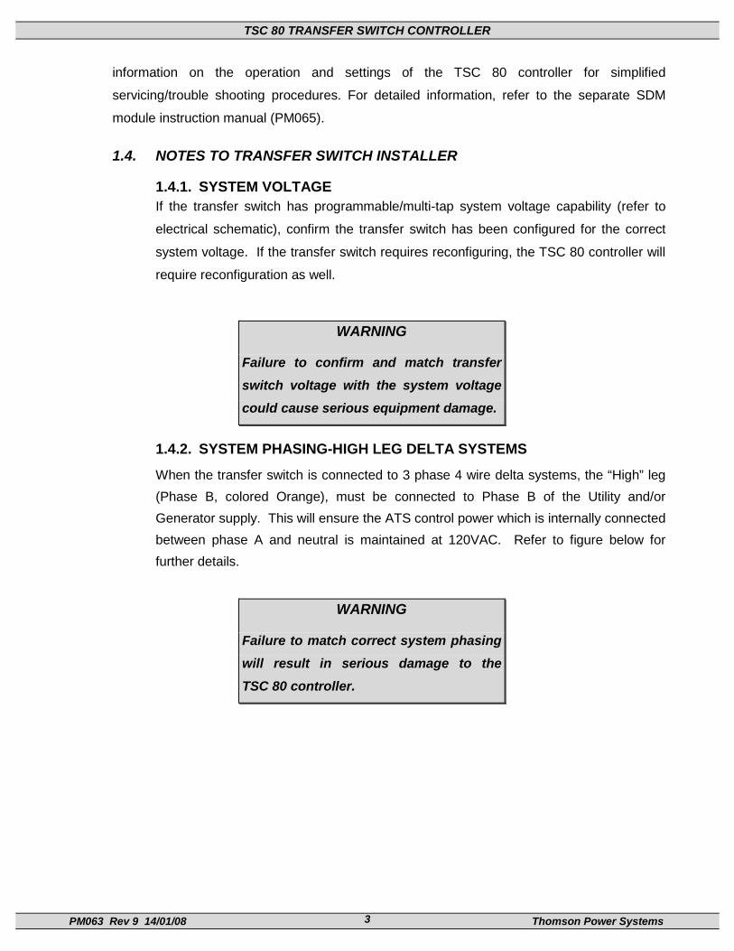
1.4.2. SYSTEM PHASING-HIGH LEG DELTA SYSTEMS
When the transfer switch is connected to 3 phase 4 wire delta systems, the “High” leg (Phase B, colored Orange), must be connected to Phase B of the Utility and/or Generator supply. This will ensure the ATS control power which is internally connected between phase A and neutral is maintained at 120VAC. Refer to figure below for further details.
WARNING
Failure to match correct system phasing will result in serious damage to the TSC 80 controller.

TSC 80 TRANSFER SWITCH CONTROLLER
PM063 Rev 9 14/01/08 Thomson Power Systems 4
208V
B(Orange)
(High Leg)
C(Yellow)
A(Red)
N(White)
PH A(UA)
Automatic TransferSwitch (Utility Supply)
PH B(UB)
PH C(UC)
Neural(N)
120V 120V
240V 240V
CAUTION!!!
All installation and/or service work performed must be done by qualified personnel only. Failure to do so may cause personal injury or death.
1.4.3. REMOTE START CONTACT FIELD WIRING
As a minimum, the remote engine start control field wiring shall conform to the local regulatory authority on electrical installations. Field wiring of a remote start contact from a transfer switch to a control panel should conform to the following guidelines to avoid possible controller malfunction and/or damage.

TSC 80 TRANSFER SWITCH CONTROLLER
PM063 Rev 9 14/01/08 Thomson Power Systems 5
1.4.3.1.Minimum #14 AWG (2.5mm2) wire size shall be used for distances up to 100ft (30m)1). For distances exceeding 100 ft. (30m) consult Thomson Power Systems.
1.4.3.2.Remote start contact wires should be run in a separate conduit.
1.4.3.3.Avoid wiring near AC power cables to prevent pick-up of induced voltages.
1.4.3.4.An interposing relay may be required if field-wiring distance is excessively long (i.e. greater than 100 feet (30m)) and/or if a remote contact has a resistance of greater than 5.0 ohms.
1.4.3.5.The remote start contact must be voltage free (i.e. dry contact). The use of a “powered” contact will damage the transfer controller.
1.4.4. DIELECTRIC TESTING Do not perform any high voltage dielectric testing on the transfer switch with the TSC
80controller connected into the circuit as serious damage will occur to the controller.
All AC control fuses and control circuit isolation plugs connected to the TSC 80 must
be removed if high voltage dielectric testing is performed on the transfer switch.

TSC 80 TRANSFER SWITCH CONTROLLER
PM063 Rev 9 14/01/08 Thomson Power Systems 6
2. DESCRIPTION The TSC 80 controller utilizes microprocessor-based design technology, which provides high accuracy for all voltage sensing and timing functions. The TSC 80 is factory configured to control all the operational functions and display features of the automatic transfer switch. The TSC 80 controller consists of two parts; a Lexan faceplate, which is mounted externally on the transfer switch door, and a printed circuit board (PCB), which is mounted inside the transfer switch on the enclosure door.
2.1. LEXAN FACEPLATES
The TSC 80 Controller Lexan faceplate is shown as in FIGURE 1. The Lexan pushbuttons and LED lights are connected to the main PCB via plug-in ribbon cable. The main features of the Lexan faceplate are described as follows with reference to FIGURE 1. Utility Supply Available LED light
Load on Utility supply LED light
Load on Generator supply LED light
Generator Supply Available LED light
ATS Load Bus Energized LED light
Utility Power Fail Test Mode Pushbutton & LED light
Auto Generator Exercise Mode Pushbutton & LED light

TSC 80 TRANSFER SWITCH CONTROLLER
PM063 Rev 9 14/01/08 Thomson Power Systems 7
FIGURE 1- TSC 80 Controller Lexan Faceplate

TSC 80 TRANSFER SWITCH CONTROLLER
PM063 Rev 9 14/01/08 Thomson Power Systems 8
2.2. PRINTED CIRCUIT BOARD
TB2-5
TRANSFORMER
10987654321
111
28
TRANSFORMER
44
38600V480V380V240V50HZ1 PhaseNo XferSecure
GenWarm-up
Gen UV
Gen Freq Utility Return
NeutralDelay
Utility UV
Gen Start GenCooldown
TB1
TB7
JP5
SYS OKXFER UTIL
XFER GEN
LD ON GEN
LD ON UTIL
ENG STOP
29
37PROG 2
PROG 3
PROG 1
TB6
TSC 80eONLY
BT1
REAL TIMECLOCKBATTERY(TSC80e only)
FIGURE 2
The printed circuit board (PCB) is shown in FIGURE 2. The PCB contains the following user interface items:
2.2.1. TERMINAL BLOCKS
Terminal blocks are located on the PCB as follows: TB1 high voltage sensing terminal block (120-600VAC).
WARNING
TSC 80 TRANSFER SWITCH CONTROLLER
PM063 Rev 9 14/01/08 Thomson Power Systems 9
Voltage sensing circuits are capable of lethal voltages while
energized. Standard safety procedures should be followed and
be performed by qualified personnel only. Failure to do so may
cause personnel injury and/or death.
TB2-6 transfer control terminal block for 115VAC control power and input/output circuits. TB7 low voltage (5Vdc) control inputs.
2.2.2. DIAGNOSTIC LED’S
The TSC 80 controller provides diagnostic LED lights, which are mounted on the printed circuit board as per FIGURE 2. Their functions are described as follows:
SYS OK This LED flashes on and off at irregular intervals, which indicates the microprocessor is functioning normally.
TRANSFER TO UTILITY This LED is illuminated whenever the TSC 80 is initiating a signal to transfer to the Utility supply.
TRANSFER TO GEN This LED is illuminated whenever the TSC 80 is initiating a signal to transfer to the Generator supply.
ENGINE STOP This LED is illuminated whenever the TSC 80 is initiating an Engine STOP signal.

TSC 80 TRANSFER SWITCH CONTROLLER
PM063 Rev 9 14/01/08 Thomson Power Systems 10
2.2.3. ADJUSTMENT POTENTIOMETERS
The TSC 80 controller utilizes eight adjustment potentiometers, which are mounted on the printed circuit board as per FIGURE 2. They are used for adjustment of all time delays, voltage and frequency setpoints. All potentiometers will be set to factory default values. Refer to Section 4.0 (CONFIGURATION INSTRUCTIONS) for further information.
2.2.4. CONFIGURATION JUMPERS
The TSC 80 controller utilizes eight Configuration Jumpers, which are mounted on the printed circuit board as per FIGURE 2. They are used for configuration of main system operating parameters such as voltage, frequency and phases. Refer to Section 4.0 (CONFIGURATION INSTRUCTIONS) for further information.
2.3. TSC 80 CONTROLLER FEATURES
The Thomson Power Systems TSC 80 Transfer Switch Controller utilizes the latest advancements in microprocessor technology, printed circuit board assembly and software for control of automatic transfer switches. The TSC 80 is the second generation of microprocessor-based transfer switch controllers from Thomson Power Systems, and reflects over 30 years of transfer switch control experience. The TSC 80 is factory configured to monitor, display and control all operational functions of the automatic transfer switch. All voltage sensors and timers are fully user adjustable utilizing potentiometers, which requires no software configuration. The microprocessor design provides high accuracy for all voltage sensing and timing functions as well as providing many standard features.
• Utility AC voltage sensing (true RMS) – 120-600V single phase or 3 phase
• Generator AC voltage sensing (true RMS) – 120-600V single phase or 3 phase
• Generator AC frequency sensing
• Utility under voltage control setpoint 70 - 95% (adjustable)
• Generator under voltage control setpoint 70 - 95% (adjustable)
• Generator under frequency control setpoint 70 - 90% (adjustable)
• Engine warm-up timer 0-60 sec. (adjustable)
• Utility return timer 0-30 min. (adjustable)
• Engine start timer 0-60 sec. (adjustable)
• Engine cooldown timer 0-30 min. (adjustable)

TSC 80 TRANSFER SWITCH CONTROLLER
PM063 Rev 9 14/01/08 Thomson Power Systems 11
• Neutral position delay timer 0-60 sec. (adjustable)
• Local utility power fail simulation test pushbutton & LED, door mounted
• Remote utility power fail simulation test pushbutton input (via terminal block)
• Load on utility supply & load on generator supply LED’s, door mounted
• Utility and generator source available LED’s, door mounted
• Weekly plant exercise timer (30 min. on load) manually initiated
• Local plant exercise initiate pushbutton & LED, door mounted
• Engine start contact (10A, 120/240VAC resistive max.)
• Load on utility auxiliary contact (Qty 1 only, 10A, 120/240VAC, Form C)
• Load on generator auxiliary contact (Qty 1 only, 10A, 120/240VAC, Form C)
• Transfer fail/forced transfer logic
• Automatic force transfer to alternate supply should load voltage become de-
energized
• 50 or 60Hz capable (115V control power)
• Remote Load Test/Peak Shave Input
2.4. APPLICATION INFORMATION
2.4.1. AC VOLTAGE SENSING INPUT
The TSC 80 can accept direct AC voltage sensing inputs on the generator and utility supplies from 120-600VAC (nominal). Note: Direct input voltage sensing can only be used when the system utilizes a 3 phase, 4 wire distribution system which has the neutral conductor solidly grounded. For 3 phase, 3 wire systems (i.e. no neutral) or high voltage systems, potential transformers must be used. Refer to FIGURE 3 for voltage sensing connections.

TSC 80 TRANSFER SWITCH CONTROLLER
PM063 Rev 9 14/01/08 Thomson Power Systems 12
TSC 80 / TSC 80e
1
2
3
25
26
24
VOLTAGE INPUTS
600VAC L-L, 347VAC L-N480VAC L-L, 277VAC L-N380VAC L-L, 220VAC L-N208VAC L-L, 120VAC L-N
1 PT REQUIRED FOR TRANSFER SWITCH MECHANISM POWER(MUST BE SIZED TO SUIT POWER REQUIREMENTS).
NOTE: UTILITY VOLTAGE SENSING ANDCONTROL POWER SHOWN ONLY.
BA C N
GRD
GRD
120
1
GRD
3Ø, 4W 208/380/480/600VAC DIRECT SENSING
VOLTAGE INPUTS
240VAC L-L, 120VAC L-N
NOTE: UTILITY VOLTAGE SENSING SHOWN ONLY.
TSC 80 / TSC 80e L2L1 N
1
2
3
10
25
24
GRD
GRD
26
NO CONNECTION
1Ø, 3W 120/240VAC DIRECT SENSING
1
2
3
25
26
24
NOTE: UTILITY VOLTAGE SENSING AND CONTROL POWER SHOWN ONLY.
BA C N
GRD
GRD
120V
NOTE: FOR HIGH LEG DELTA SYSTEMS PHASING OF CUSTOMER SUPPLY MUSTBE CONNECTED AS SHOWN ABOVE. FAILURE TO COMPLY WILL RESULT IN DAMAGETO CONTROLLER.
A
B C
N
3Ø, 4W 120/240V HIGH LEG DELTA DIRECT CONNECTION
TSC 80 / TSC 80e
SECONDARY PT VOLTAGE
120VAC L-L [NO NEUTRAL]
NOTE: ØB IS GROUNDED
TSC 80 / TSC 80eBA C
1
2
3
25
26
24
GRD
120
1
120
120
1 PT REQUIRED FOR TRANSFER SWITCH MECHANISM POWER(MUST BE SIZED TO SUIT POWER REQUIREMENTS).
NOTE: UTILITY VOLTAGE SENSING SHOWN ONLY.
GRD
GRD
38
43
3Ø, 3W DELTA PT's
FIGURE 3

TSC 80 TRANSFER SWITCH CONTROLLER
PM063 Rev 9 14/01/08 Thomson Power Systems 13
2.4.2. AC CONTROL POWER INPUT
The TSC 80 is factory supplied for 115VAC (nominal) control power input voltage. Independent AC control power is required from both utility and generator supplies. AC control power is utilized for internal TSC 80 control circuits and external control device loads. The TSC 80 requires approximately 6 VA power for internal control circuits. The maximum external load is limited by output contact ratings (i.e. 10A resistive, 120VAC). Total AC control power requirements for each supply must be determined by adding both internal and external load requirements.
2.4.3. OUTPUTS
The TSC 80 provides the following types of output circuits:
Engine Start Contact Isolated Form B contact (10A, 120VAC Resistive) Load on Utility Isolated Form C contact (10A, 120VAC/250VAC
Resistive) Load on Generator Isolated Form C contact (10A, 120VAC/250VAC
Resistive) Transfer to Utility Output 120VAC, 10A (Resistive) powered output contact Transfer to Generator Output 120VAC, 10A (Resistive) powered output contact
Interposing relays are required between the TSC 80 outputs and the end device if loads exceed the output current rating.

TSC 80 TRANSFER SWITCH CONTROLLER
PM063 Rev 9 14/01/08 Thomson Power Systems 14
3. OPERATING INSTRUCTIONS To operate the TSC 80 controller and associated transfer switch using the front faceplate pushbuttons, refer to the following detailed operating instruction sub-section descriptions.
3.1. AUTOMATIC SEQUENCE OF OPERATION
3.1.1. NORMAL OPERATION Under normal operating conditions, the transfer switch operates automatically during a
failure and restoration of utility power and does not require operator intervention.
When utility supply voltage drops below a preset nominal value (70 - 95% of rated
adjustable) on any phase, an engine start delay circuit will be initiated and the transfer
to utility supply signal will be removed (i.e. contact opening). Following expiry of the
engine start delay period (0 - 60 sec. adjustable) an engine start signal (contact
closure) will be given.
Once the engine starts, the transfer switch controller will monitor the generators
voltage and frequency levels. Once the generator voltage and frequency rises above
preset values (70 - 95% nominal adjustable) the Engine Warm-up timer will be initiated.
Once the Engine Warm-up timer expires (0-60 sec. Adjustable), the transfer to
generator supply signal (contact closure) will be given to the transfer switch
mechanism. The load will then transfer from the utility supply to the generator supply
via motor driven mechanism.
The generator will continue to supply the load until the utility supply has returned and
the retransfer sequence is completed as follows: When the utility supply voltage is
restored to above the present values (70 - 95% of rated adjustable) on all phases, a
transfer return delay circuit will be initiated. Following expiry of the utility transfer return
timer (0 - 30 min. adjustable), the transfer to generator supply signal will be removed
(contact opening), then the transfer to utility supply signal (contact closure) will be
given to the transfer switch mechanism. The load will then be transferred from the
generator supply back to the utility supply. During the utility re-transfer sequence a
neutral position delay circuit will cause the transfer mechanism to pause in the “neutral
position (i.e. with both transfer power switching devices open) for the duration of the
neutral delay timer (0-30 seconds adjustable) setting. Once the time delay expires, the
re-transfer sequence will be completed.

TSC 80 TRANSFER SWITCH CONTROLLER
PM063 Rev 9 14/01/08 Thomson Power Systems 15
An engine cooldown timer circuit will be initiated once the load is transferred from the
generator supply. Following expiry of the cooldown delay period (0 - 30 min.
adjustable) the engine start signal will be removed (contact opening) to initiate stopping
of the generator set.
3.1.2. ABNORMAL OPERATION
3.1.2.1.TEST CONDITION A test pushbutton on the transfer switch shall signal a simulated utility power fail
signal to the transfer switch controller. The transfer switch shall operate as per
a normal utility power fail condition. The neutral delay circuit logic will be active
during transfer to and from the generator supply (i.e. when both sources of
power are available).
The transfer switch shall remain on generator supply until the test mode is
terminated. It will then retransfer back to the utility supply following the transfer
return timer and then continue to operate the generator set for its cooldown
period then stop.
3.1.2.2.GENERATOR FAILURE ON LOAD Should the generator set fail while on load, the transfer switch shall retransfer
the load back to the utility supply if within nominal limits. The utility return timer
will be bypassed in this condition.
NOTE This operating condition shall apply to a normal utility failure as
well as any test condition.
3.1.2.3.TRANSFER SWITCH FAIL ALARM LOGIC
The TSC 80 controller contains logic to detect a transfer mechanism failure. Should a failure be detected, a forced transfer to the alternate supply will be initiated. Detailed logic operation is as follows:
NOTE
The “TRANSFER SWITCH FAIL” feature can be disabled by
activating the “Service Entrance” Mode by jumpering terminal
numbers 38 & 42. The TSC 80 controller will not verify that the
transfer mechanism has operated correctly.
TSC 80 TRANSFER SWITCH CONTROLLER
PM063 Rev 9 14/01/08 Thomson Power Systems 16
3.1.2.4.TRANSFER FAIL DETECTION-NORMAL STEADY STATE CONDITION (NON-TRANSFERRING)
i. Limit Switch Failure (i.e. open contact) - Transfer Fail Alarm is initiated
(Load on Source Flashing LED) after 9 second delay, and then a forced
transfer to the alternate source is initiated. Re-transfer back to the original
source will not occur until the Transfer Fail alarm condition is reset. Refer
to item 3.3 for Transfer Fail Fault Reset details.
ii. Loss of Load Voltage (<80VAC) (i.e. Power switching device Tripped
Condition) - Transfer Fail Alarm is initiated (Load Source Flashing LED)
after 5 second delay, then a forced transfer to the alternate source is
initiated. Re-transfer back to the original source will not occur until the
Transfer Fail alarm condition is reset. Refer to item 3.3 for Transfer Fail
Fault Reset details.
iii. Limit Switch Failure & Loss of Load Voltage <80VAC - Transfer Fail Alarm
is initiated (Load Source Flashing LED) after 11 second delay, then a
forced transfer to the alternate source is initiated. Re-transfer back to the
original source will not occur until the Transfer Fail alarm condition is reset.
Refer to item 3.3 for Transfer Fail Fault Reset details.
3.1.2.5.TRANSFER FAIL DETECTION - TRANSFERRING CONDITION Transfer Source to Neutral – “NEUTRAL POSITION TIME” (10 seconds-
adjustable with SDM) starts timing as soon as a transfer to the alternate source
is initiated. During this period the ATS motor is energized and moves the
mechanism from the original source to neutral. The power to the motor will be
de-energized when either the “NEUTRAL POSITION TIME” times out or the
load voltage drops below 80VAC on all phases (whichever occurs first). Once
the ATS motor is de-energized, the Neutral Delay timer starts timing. Once the
Neutral Delay timer times out the motor re-energizes to continue the transfer
(see below). Note: Normally the load voltage will typically drop below the
setpoint within 1 second when the source power switching device opens and
therefore the “NEUTRAL POSITION TIME” never times out. The default setting
of this timer (10 seconds) is intentionally set long so that it will not pre-maturely
stop the ATS mechanism.
Transfer Neutral to Source– “Find Neutral/Source Timer” starts timing as soon
as the Neutral Delay timer times out. During this period the motor is energized
and moves the mechanism from the neutral to the alternate source. The power

TSC 80 TRANSFER SWITCH CONTROLLER
PM063 Rev 9 14/01/08 Thomson Power Systems 17
to the ATS motor will be de-energized when either the mechanism’s limit switch
activates (i.e. external logic to the TSC 80) or the “Find Neutral/Source Timer”
times out (whichever occurs first). Note: During the above 2 sequences the
“Transfer Fail Alarm” logic is inhibited. Once the 2 sequences have been
completed, the “Transfer Fail Alarm” logic will be re-enabled and will only be
triggered if conditions as described in item A (Normal Steady State Condition)
are sensed (limit switch and/or loss of load voltage).
For example, if the ATS mechanism fails to move (i.e. due to broken rod, motor
failure or manual release plunger not re-engaged), the total time before a
transfer fail will be initiated is 31 seconds (i.e. Find Neutral/Source Timer” 10
sec + Find Neutral/Source Timer” (10 sec)+ Limit Switch Failure & Loss of
Load Voltage <80VAC = 31 seconds).
3.1.2.6.SERVICE ENTRANCE ATS For Service Entrance Rated transfer switch applications, the transfer switch
control logic will include external wiring to signal the transfer switch mechanism
to move to the “Service Disconnected” position. In this mode the TSC 80
transfer control outputs and Transfer Fail feature is disabled.
3.2. TEST MODES
3.2.1. UTILITY POWER FAIL SIMULATION (LOAD TEST) To simulate a utility power failure condition, press the UTILITY POWER FAIL
SIMULATE pushbutton on the Lexan faceplate. Hold the pushbutton on for
approximately 5 seconds until the LED light above the pushbutton changes
state. Once the mode is initiated, the engine start will be activated, once the
engine accelerates to nominal voltage and frequency levels, the load will
automatically transfer to the generator supply. To terminate the Utility Power
Fail Test Mode, the Test pushbutton must be held on for approximately 5
seconds until the LED light above the pushbutton changes state. When the
pushbutton is released the LED light will go out and, the load will re-transfer
back to the utility supply following expiry of the Utility Return delay timer.
NOTE
The load will automatically re-transfer to the utility supply should
the generator fail while on load.

TSC 80 TRANSFER SWITCH CONTROLLER
PM063 Rev 9 14/01/08 Thomson Power Systems 18
3.2.2. AUTOMATIC PLANT EXERCISE TEST Automatic Plant Exercise operation is dependent upon the type of Transfer Controller
as described below:
3.2.2.1.TSC 80 AUTOMATIC PLANT EXERCISE TEST
The TSC 80 controller has a fixed 30-minute/ 7-day weekly automatic plant exercise program. The generator set will be exercised either “on or off” load dependent upon the controller configuration (refer to section 4.1.4). To initiate a 30 minute /7 day weekly automatic plant exercise mode, press the GENERATOR EXERCISE Mode pushbutton on the Lexan faceplate. Hold the pushbutton on for approximately 5 seconds until the LED light above the pushbutton changes state. Once the mode is initiated, the engine will immediately start and transfer on load (i.e. if configured for On Load Test) once nominal voltage and frequency levels have been obtained. The engine will remain operating on load until the plant exercise time delay period of 30 minutes expires, then the load will re-transfer back to the utility supply. The engine will be automatically re-tested on load every week (e.g.7 days) at the same time of day.
NOTES
1. The load will automatically re-transfer to the utility supply
should the generator fail while in the test mode.
2. To bypass a 30-minute exercise run period, press and hold
the Exercise pushbutton on for 5 seconds until the LED remains
on.
The Generator Exercise LED light will operate as follows:
LED ON - Exercise Timer is initiated, the 7-day timer is active and the
generator is in the off state.
LED FLASHING - Exercise Timer is initiated, the 30 minute run timer is
active and the generator is running on loads.
LED OFF - Exercise Timer is not initiated and the 7-day timer is not
active.
To terminate the Generator Exercise Mode, the Exercise pushbutton must be
held on for approximately 5 seconds until the LED light above the pushbutton
starts flashing. When the pushbutton is released, the LED light will go out and
the system will return to normal operation.

TSC 80 TRANSFER SWITCH CONTROLLER
PM063 Rev 9 14/01/08 Thomson Power Systems 19
NOTE
To enable the Auto Exercise mode without initiating an
immediate exercise test, operator must first turn the gen set
engine control to off, then press the Exercise button once, then
press it a second time to cancel the test. The gen set engine
control should then be returned back to the Automatic position.
3.2.3. FOUR FUNCTION REMOTE TEST (FTS4 OPTION)
The function of the Four Position Test Switch Input is to allow operators to select various operating scenarios for test or maintenance purposes, in addition to the use of the faceplate mounted pushbuttons.
NOTE: When an external FTS4 switch is used, the TSC 80 operation as selected from the faceplate pushbuttons will be overridden.
OFF: Disables the engine start output from the transfer switch. If the primary source is available, and within normal limits, the TSC 80 will initiate a transfer to the primary source. The transfer switch will not automatically transfer to the secondary (alternate) source should the primary source fail.
AUTO: All automatic functions are enabled.
ENGINE START: (No load test) An engine start signal will be initiated and will remain on until the FTS4 is placed in another position. The engine will start if the engine’s auto start controller is in the ”Auto” mode. If the primary source fails in this mode, and the secondary source is within parameters, the TSC 80 will initiate a transfer to the secondary source. When the Engine Start input is removed, the generator will continue to run if it has not operated for a time equal to or greater than the minimum run time (i.e. based on the Engine Cooldown Timer setting).
TEST: (Full load test) A primary source failure is simulated and an engine start signal will be initiated. When the secondary source is within normal limits, the TSC 80 will initiate a transfer to the secondary source. The system will remain in this state until the FTS4 is placed in another position or the secondary supply fails. Upon a secondary

TSC 80 TRANSFER SWITCH CONTROLLER
PM063 Rev 9 14/01/08 Thomson Power Systems 20
supply failure, if the primary supply is available, the TSC 80 will initiate a transfer to the primary supply. The Engine Cooldown time sequence will be initiated when the test mode is terminated.
3.2.4. REMOTE TEST To activate a remote load test, a contact is to be remotely closed between terminal #44
and terminal #38. When the contact closes, and engine start will be activated and once
the engine accelerates to nominal voltage and frequency levels, the load will
automatically transfer to the generator supply. When the remote contact is opened, the
load will re-transfer back to the utility supply following expiry of the Utility Return delay
timer. The Engine Cooldown time sequence will be initiated when the test mode is
terminated.
NOTE
The load will automatically re-transfer to the utility supply should
the generator fail while on load.
3.3. TRANSFER FAIL FAULT RESET To reset a Transfer Fail condition (i.e. When either the Load on Gen or Load on Utility
LEDs are flashing and the ATS load is transferred to the alternate source), both Lexan
faceplate pushbuttons (i.e. UTILITY POWER FAIL SIMULATE & GENERATOR
EXERCISE MODE) must be held on for approximately 5 seconds until all LEDs on the
Lexan start flashing and UTILITY POWER FAIL SIMULATE LED flashes in opposition.
Once the alarm condition is reset, the load will automatically retransfer back to the
original source if within normal limits.
3.4. LAMP TEST To initiate a Lamp Test, both Lexan faceplate pushbuttons (i.e. UTILITY POWER FAIL
SIMULATE & GENERATOR EXERCISE MODE) must be held on longer than 5
seconds until all LEDs on the Lexan illuminate in a flashing mode.
NOTE
The Lamp Test Function will also clear a transfer failure alarm
and will allow active timers to be bypassed if the lamp test is
held on for longer than 5 seconds.

TSC 80 TRANSFER SWITCH CONTROLLER
PM063 Rev 9 14/01/08 Thomson Power Systems 21
3.5. TIMER BYPASS To bypass an active timing sequence (e.g. utility return timer, cooldown timer, warm-up
timer) during operation, both Lexan faceplate pushbuttons (i.e. UTILITY POWER FAIL
SIMULATE & GENERATOR EXERCISE MODE) must be held on for approximately 5
seconds until all LEDs on the Lexan start flashing and UTILITY POWER FAIL
SIMULATE LED flashes in opposition.

TSC 80 TRANSFER SWITCH CONTROLLER
PM063 Rev 9 14/01/08 Thomson Power Systems 22
4. TSC 80 CONFIGURATION INSTRUCTIONS
All user configuration of the TSC 80 controller is accomplished using either hardware jumpers or potentiometers located on the printed circuit board as per FIGURE 2. No software programming is required. The hardware jumpers and potentiometers are used for configuration of main operating parameters such as system voltage, frequency, phases, adjustable time delays, voltage sensor settings and frequency sensor settings. All configuration jumpers and potentiometers are set to factory default values as required for the Transfer Switch and should not require further setting.
4.1. CONFIGURATION JUMPERS
The following configuration jumpers are provided on the printed circuit board to
program the TSC 80 controller:
WARNING
The configuration jumper settings must not be changed while
the Transfer Switch and TSC 80 controller are energized. All
sources of power to the transfer switch must be de-energized
prior to changing any configuration jumper settings. Failure to
do so may cause personnel injury and/or death.
4.1.1. SYSTEM VOLTAGE
Four jumpers are provided to set the required system operating voltage of the
TSC 80 controller. Jumpers are provided for each typical system Phase-to-
Phase Voltage (i.e. 600V, 480V, 380V, 240V).
To activate the required system voltage setting, a jumper must be placed
across the 2 pins, adjacent to the text on the PCB. Only one jumper must be
placed on the voltage selection jumpers. Failure to do so will cause improper
operation.
NOTES

TSC 80 TRANSFER SWITCH CONTROLLER
PM063 Rev 9 14/01/08 Thomson Power Systems 23
1. For 208V nominal system voltage, no jumpers are required
on any of the voltage jumper pins.
2. For 3 phase 3 wire or high voltage applications utilizing 120V
sensing input voltage, no jumpers are required on any of the
voltage jumper pins and Terminal #43 must be jumpered to
Terminal #38.
3. For nominal system voltages that are not provided by specific
configuration jumper pins, contact Thomson Power Systems for
further information.
4. If multiple jumpers are incorrectly left on the voltage selection
pins, the highest voltage selected will have precedence.
When a system voltage is selected, the TSC 80’s utility and generator under
voltage setpoint percentage setting will be automatically programmed to
correspond to the sensing input voltage (e.g. with a 600V system voltage
selected, and a 80% under voltage potentiometer setting, the under voltage
sensor will be activated below 540VAC).
NOTE
When a configuration jumper is not required, the jumper should
be connected to only one pin of the header to conveniently store
it for future use.

TSC 80 TRANSFER SWITCH CONTROLLER
PM063 Rev 9 14/01/08 Thomson Power Systems 24
4.1.1.1.TSC 80 UNDER VOLTAGE SETPOINTS WITH NON-STANDARD SYSTEM VOLTAGES
When the Transfer Switch & TSC 80 transfer controller is applied to non-
standard system voltages, the TSC 80 under voltage potentiometer setting
percentages on the printed circuit board will not correspond to the correct
voltage drop out setting.
To obtain the correct drop-out voltages using non-standard system voltages,
the TSC 80 potentiometers need to have an offset percentage adjustment with
the corresponding Voltage Jumper settings. These are shown in the following
table for typical 85% drop-out under voltage setpoints.
System Voltage
ATS Transformer Tap Setting
TSC 80 Voltage Jumper Setting
85% Drop-out Voltage
TSC 80 Under voltage
Potentiometer Setting
208V 208V tap No jumper = 208V
177V 85%
220V 240V tap 240V 187V 78% 230V 240V tap 240V 195V 81% 240V 240V tap 240V 204V 85% 440V 480V tap 480V 374V 78% 460V 480V tap 480V 391V 81% 480V 480V tap 480V 408V 85% 575V 600V tap 600V 489V 82%
380V/50Hz 392V tap (use 208V to 600V
primary connection)
380V 323V 85%
400V/50Hz 392V tap (use 208V to 600V
primary connection)
480V 340V 71%
To obtain the most accurate setting of the potentiometer (other than visually on the
printed circuit board), a Service Display Module (SDM) is recommended.
For other non-standard system voltages, the following formula can be used:
A) Desired Drop-out Voltage= Drop-out % x System Voltage
B) TSC 80 POT Setting = (Desired Drop-out voltage x 100)
TSC 80 Voltage Jumper Setting
Example: for 440V system, 85% of 440V= .85 x 400V= 374V

TSC 80 TRANSFER SWITCH CONTROLLER
PM063 Rev 9 14/01/08 Thomson Power Systems 25
TSC 80 POT Setting = (374 x 100) 480
TSC 80 POT Setting = 78%
NOTE The TSC 80 voltage jumper setting must be set to be equal to the
nominal system voltage level or the next highest setting available (e.g.
440V system voltage must use 480V jumper setting).
4.1.2. SYSTEM FREQUENCY
One jumper is provided to set the required system operating frequency of the
TSC 80 controller.
• For 60Hz applications, no configuration jumper is required.
• For 50Hz applications, a jumper must be placed across the 2 pins,
adjacent to the text on the PCB.
When a system frequency is selected, the TSC 80’s generator frequency
setpoint percentage setting will be automatically programmed to correspond to
the sensing input frequency (e.g. with a 60Hz system frequency, and a 90%
under frequency potentiometer setting, the under frequency sensor will be
activated below 54.0 Hz).
NOTE
When a configuration jumper is not required, the jumper should
be connected to only one pin of the header to conveniently store
it for future use.
4.1.3. SYSTEM PHASES
One jumper is provided to set the required number of system phases for the
TSC 80 controller.
• For 3 phase applications, no configuration jumper is required.
• For single-phase applications, a jumper must be placed across the 2
pins, adjacent to the text on the PCB. Phase C voltage sensing input is
ignored in the single-phase mode.
NOTE

TSC 80 TRANSFER SWITCH CONTROLLER
PM063 Rev 9 14/01/08 Thomson Power Systems 26
When a configuration jumper is not required, the jumper should
be connected to only one pin of the header to conveniently store
it for future use.
4.1.4. GEN EXERCISE LOAD TEST MODE (NO XFER)
A configuration jumper is provided to select the desired testing mode (i.e. load
test with transfer or no-load test) for the 7 day/30 minute generator exercise
function or for a remotely initiated Test mode. One jumper is provided to set
the desired test mode as follows:
• Load Test Gen Exercise Test Mode: no program jumper is required.
NOTE
The No-Load Test mode is the factory default setting.
• No-Load Gen Exercise Test Mode: program jumper is required to be
placed across the 2 pins, adjacent to the text on the PCB.
NOTE
Should utility power fail during a no-load test operation, the load
will automatically transfer to the generator and will re-transfer
back when utility power is restored to within normal conditions.
The engine will continue to run until the 30 minute exercise time
delay period expires.
NOTE
When a configuration jumper is not required, the jumper should
be connected to only one pin of the header to conveniently store
it for future use.
4.1.5. SECURE
A configuration jumper is provided to inhibit the test pushbuttons on the Lexan
faceplate, for security purposes.
• For normal automatic transfer switch operation, no configuration jumper
is required.

TSC 80 TRANSFER SWITCH CONTROLLER
PM063 Rev 9 14/01/08 Thomson Power Systems 27
• To inhibit the test pushbuttons on the Lexan faceplate for security
purposes, a jumper must be placed across the 2 pins, adjacent to the
text on the PCB.
If the jumper was placed to inhibit the test pushbuttons subsequent to an Exercise Test mode being activated, the Gen Exercise test mode will be immediately terminated. If utility power fail test mode is selected prior to placing the inhibit configuration jumper on, the test continue to operate until manually terminated by pressing the Test pushbutton for 5 seconds.
NOTE
When a configuration jumper is not required, the jumper should
be connected to only one pin of the header to conveniently store
it for future use.
4.2. TSC 80 ADJUSTMENT POTENTIOMETERS
Eight adjustment potentiometers are provided on the TSC 80 controller printed circuit
board. Refer to Figure #2 which illustrates how the potentiometers are arranged on the
printed circuit board. A listing of available features which are user adjustable via the
PCB potentiometers is shown in Table #1. A small flat blade screwdriver is required to
adjust the potentiometers. Turning the potentiometer in the clockwise position will
cause an increase in function setting and visa-versa for counter-clockwise pot rotation.

TSC 80 TRANSFER SWITCH CONTROLLER
PM063 Rev 9 14/01/08 Thomson Power Systems 28
TABLE 1 USER ADJUSTABLE FEATURES
Function Factory Default Setting Range Engine Start Timer 3 seconds 0-60 sec
Engine Warm-up Timer 2 seconds 0-60 sec
Engine Cooldown Timer 2 minutes 0-30 min
Utility Return Timer 2 minutes 0-30 min
Neutral Delay Timer 3 seconds 0-60 sec
Utility Under Voltage Sensor (Drop-Out Setting) 85% 70-95%
Generator Under Voltage Sensor (Drop-Out Setting) 85% 70-95%
Generator Frequency Sensor 90% 70-90%
4.2.1. UTILITY UNDER VOLTAGE SETPOINT
A potentiometer is provided to adjust the setpoint of the TSC 80’s utility under voltage
sensor. The under voltage setting is expressed in percentage of system voltage setting
with an adjustable range of 70-95% (e.g. If system voltage configuration jumper is set
for 600V, an 80% under voltage setting will correspond to an actual 540VAC setpoint.)
NOTE
The actual under voltage setpoint voltage is calculated based
on the TSC 80 voltage configuration jumper setting (i.e. nominal
system voltage) and the potentiometer setting. Actual system
operating voltage should not be used to calculate the under
voltage setpoint.
The under voltage setting is for a falling utility voltage (i.e. “drop-out” setting) on any
one phase. The under voltage sensor will reset to normal when the utility voltage rises
5% above the “drop-out setting (i.e. differential value). Example: if under voltage is
adjusted to an 80% drop-out value, it will reset at 85% voltage. The 5% differential
value is not programmable.
NOTE

TSC 80 TRANSFER SWITCH CONTROLLER
PM063 Rev 9 14/01/08 Thomson Power Systems 29
To override momentary under voltage fluctuations, the TSC 80’s
Engine Start Delay Timer feature is utilized.
Refer to Table 1 for the factory default settings of the utility under voltage sensor.
4.2.2. GENERATOR UNDERVOLTAGE SETPOINT
A potentiometer is provided to adjust the setpoint of the TSC 80’s generator under
voltage sensor. The under voltage setting is expressed in percentage of system
voltage setting with an adjustable range of 70-95% (e.g. If system voltage
configuration jumper is set for 600V, an 80% under voltage setting will correspond to
an actual 540VAC setpoint.)
NOTE
The actual under voltage setpoint voltage is calculated based
on the TSC 80 voltage configuration jumper setting (i.e. nominal
system voltage) and the potentiometer setting. Actual system
operating voltage should not be used to calculate the under
voltage setpoint.
The under voltage setting is for a falling generator voltage (i.e. “drop-out” setting) on
any one phase. The under voltage sensor will reset to normal when the generator
voltage rises 5% above the “drop-out setting (i.e. differential value). Example: if under
voltage is adjusted to an 80% drop-out value, it will reset at 85% voltage. The 5%
differential value is not programmable.
NOTE
To override momentary under voltage fluctuations, the under
voltage sensor is provided with a transient time delay period of
3 seconds which is non-adjustable.
Refer to Table 1 for the factory default settings of the generator under voltage sensor.
4.2.3. GENERATOR UNDER FREQUENCY SETPOINT
A potentiometer is provided to adjust the setpoint of the TSC 80’s generator under
frequency sensor. The under frequency setting is expressed in percentage of system
frequency setting with an adjustable range of 70-90% (e.g. If system frequency

TSC 80 TRANSFER SWITCH CONTROLLER
PM063 Rev 9 14/01/08 Thomson Power Systems 30
configuration jumper is set for 60Hz, an 90% under frequency setting will correspond to
an actual 54Hz setpoint.).
NOTE
The actual under frequency setpoint voltage is calculated
based on the TSC 80 voltage configuration jumper setting (i.e.
nominal system frequency) and the potentiometer setting.
Actual system operating frequency should not be used to
calculate the under frequency setpoint.
The under frequency setting is for a falling generator frequency (i.e. “drop-out” setting)
on any one phase. The under frequency sensor will reset to normal when the generator
frequency rises 0.5% above the “drop-out setting (i.e. differential value). Example: if
under frequency is adjusted to an 80% drop-out value (i.e. 48.0Hz), it will reset at
48.3Hz. The 0.5% differential value is not programmable.
NOTE
To override momentary under frequency fluctuations, the under
frequency sensor is provided with a transient time delay period
of 3 seconds which is non-adjustable.
Refer to Table 1 for the factory default settings of the generator under frequency
sensor.
4.2.4. ENGINE START DELAY
A potentiometer is provided to adjust the TSC 80’s Engine Start Delay timer. The
engine start signal will be initiated following expiry of the start delay timer. Select
desired Engine Start time delay in seconds. The range of setting is 0 to 60 seconds.
If no delay is required, set this time delay to zero.
NOTE
The output relay is normally energized when the utility power is
within limits and de-energizes to start the engine.
Refer to Table 1 for the factory default settings of the Engine Start Delay timer.
4.2.5. ENGINE WARMUP DELAY

TSC 80 TRANSFER SWITCH CONTROLLER
PM063 Rev 9 14/01/08 Thomson Power Systems 31
A potentiometer is provided to adjust the TSC 80’s Engine Warm-up Delay timer. A
transfer to the generator supply will be initiated when the voltage and frequency are
within limits and upon expiry of the Engine Warm-up delay timer. The range of setting
is 0 to 60 seconds. If no delay is required, set this time delay to zero.
Refer to Table 1 for the factory default settings of the Engine Warm-up Delay timer.
4.2.6. ENGINE COOLDOWN DELAY A potentiometer is provided to adjust the TSC 80’s Engine Cooldown Delay timer. The.
Engine Cooldown period will be initiated once the load has transferred from the
generator supply. The engine start signal will be maintained until expiry of the
cooldown delay timer. The range of setting is 0 to 30 minutes. If no delay is required,
set this time delay to zero.
Refer to Table 1 for the factory default settings of the Engine Cooldown Delay timer.
4.2.7. UTILITY RETURN DELAY A potentiometer is provided to adjust the TSC 80’s Utility Return Delay timer. The
Utility Return delay period will be initiated once the utility supply has returned within
limits following a utility power failure condition. The range of settings is 0 to 30
minutes. If no delay is required, set this time delay to zero.
NOTE
The utility return delay will be bypassed should the generator
fail during the time delay period.
Refer to Table 1 for the factory default settings of the Utility Return Delay timer.
4.2.8. NEUTRAL DELAY
A potentiometer is provided to adjust the TSC 80’s Neutral Delay timer. The neutral
delay time period will be initiated once the load bus voltage drops below the dead-bus
threshold value when both of the supply power switching devices are open during a
transfer sequence. Select desired neutral delay time in seconds. The range of
settings is 0 to 60 seconds. If no delay is required, set this time delay to zero.
NOTE
The neutral delay will be bypassed should the operating power
fail for longer than the timer setting.
Refer to Table 1 for the factory default settings of the Neutral Delay timer.

TSC 80 TRANSFER SWITCH CONTROLLER
PM063 Rev 9 14/01/08 Thomson Power Systems 32
5. TSC 80 TYPICAL CONNECTION DIAGRAM
TRANSFER CONTROLLERMODEL TSC 80
42
44
38
A (L1)
B (L2)
C (L3)
A (L1)
B (L2)
C (L3)
A (L1)
UTILITY SUPPLY SENSING120-600VAC
50/60Hz3 PHASE
GENERATOR SUPPLYSENSING
120-600VAC50/60Hz3 PHASE
LOAD SENSING120-600VAC
50/60Hz3 PHASE
1
2
3
4
5
6
7
CONNECTION DIAGRAM
1
1
1 UTILITY AND GENERATOR SUPPLIES MUSTUTILIZE A SOLIDLY GROUNDED NEUTRALSYSTEM. REFER TO INSTRUCTION MANUAL FORALTERNATE CONNECTIONS
REVISED 08-08-01
NOTE:3 PHASE, 4 WIRE ATS CONNECTIONSSHOWN ONLY.
SEE MANUAL FOR ALTERNATE CONNECTION DIAGRAMS
FULL FILENAMEG:\ENGINEER\PRODUCTS\TSC80\TSC80E EDITS\TSC80 EXTERNAL
CONNECTIONS - REV1.VSD
B (L2) 8
19
20
25 L
LOAD ON UTILITY SUPPLY INPUT (120VAC)
TRANSFER TO UTILITY OUTPUTRATED 10A, 120/250VAC, 10A, 30VDC RES.MAX.
LOAD ON GENERATOR SUPPLY INPUT (120VAC)
28
27
ENGINE START CONTACT(Contact closes to start engineon power failure)RATED 10A, 120/250VAC, 5A, 30VDC RES. MAX.
26 N
C (L3) 9
N 10COMMON SYSTEM
NEUTRAL OR GROUNDREFERENCE
UTILITY CONTROL POWER115VAC
REMOTE LOAD TEST(close to activate)
SERVICE ENTRANCE MODE(close to disable transfer fail logic)
5Vdc Digital Inputs
JP3
Ribbon Cable To DoorMounted Lexan Faceplate
22
18
21
L
TRANSFER TO GENERATOR OUTPUTRATED 10A, 120/250VAC, 10A, 30VDC RES. MAX.
23 N
GENERATOR CONTROLPOWER115 VAC
K4
XFER TOGEN
K8 17
Utility Interlock
NO CONNECTION
SYSTEM GROUND24
K8
XFER TOUTIL
13
12
11
LOAD ONUTILITYRATED 10A, 120/250VAC, 5A, 30VDCRES. MAX.
16
15
14
LOAD ONGENERATORRATED 10A, 120/250VAC, 5A, 30VDCRES. MAX.
43120V 3 PHASE 3 WIRESENSING
(close to activate)
COM

TSC 80 TRANSFER SWITCH CONTROLLER
PM063 Rev 9 14/01/08 Thomson Power Systems 33
6. TSC 80 SPECIFICATIONS
• POWER SUPPLY:
- 115VAC nominal (+10% -30%) - 50/60Hz - 6VA nominal (no external load connected)
• VOLTAGE SENSING: - Direct 120-600VAC nominal, single or 3 phase - 50/60Hz - +/- 1.0% accuracy of setting @ 25°C
• OPERATING TEMPERATURE: - 40°C to +50°C (TSC 80) OUTPUT CONTACTS (Form C, 10A,120/250VAC resistive) - Engine Start - Load on Utility - Load on Generator - • OUTPUT SIGNALS (120VAC resistive load)
- Transfer to utility 10A - Transfer to generator 10A

TSC 80 TRANSFER SWITCH CONTROLLER
PM063 Rev 9 14/01/08 Thomson Power Systems 34
7. TROUBLESHOOTING A number of problems can cause the TSC 80 controller not to function properly. Refer to the following
list of typical problems. Consult the factory for any detailed information or for any problems not listed.
NOTE
An optional hand held, plug-in Service Display Module
(SDM) is available for the TSC 80 Transfer Controller.
The SDM module provides an LCD screen to display
additional detailed information on the operation and
settings of the TSC 80 controller for simplified
servicing/trouble shooting procedures. For detailed
information, refer to the separate SDM module instruction
manual (PM065).
CAUTION!!! Before opening the Transfer Switch enclosure to perform any service task, it is imperative to isolate the transfer switch from any possible source of power. Failure to do so may result in serious personal injury or death due to electrical shock.
Service procedures must be undertaken by qualified personnel only!
Symptom Possible Causes
- Will not re-transfer to utility source upon restoration
- A test mode has been activated
- Utility voltage is outside the pre-programmed limits (check utility source for adequate voltage)
- A loose control connection - Faulty limit switch contact in the ATS motor circuit - Defective ATS Motor - Defective TSC 80 controller (verify output signals with circuit
board mounted diagnostic LED’s) - TSC 80 has “Transfer Fail” alarm activated which is
indicated by a flashing “Load on Utility” LED which is located on the Lexan faceplate. Determine cause of alarm and rectify before TSC 80 is reset
- Will not transfer to generator source
upon failure of utility source - Generator set not producing enough voltage/frequency or
output circuit power switching device open Symptom Possible Causes
- Warm-up time delay function has not timed out (verify TSC 80 timer setting)

TSC 80 TRANSFER SWITCH CONTROLLER
PM063 Rev 9 14/01/08 Thomson Power Systems 35
- A loose control connection - Faulty limit switch contact in the ATS motor circuit - Defective ATS Motor - Defective TSC 80 controller (verify output signals with circuit
board mounted diagnostic LED’s) - TSC 80 has “Transfer Fail” alarm activated which is
indicated by a flashing “Load on Generator” LED which is located on the Lexan faceplate. Determine cause of alarm and rectify before TSC 80 is reset
- Transfer to generator source without
a power failure in the utility source - -
A test mode has been activated Defective TSC 80 controller (verify output signals with circuit board mounted diagnostic LED’s)
- Loose or broken wire to the utility voltage sensing terminals on the TSC 80 controller
- Utility supply voltage is slightly below voltage sensing setpoints. Compare TSC 80 program voltage setpoints with actual utility voltage.
- Utility power switching device has tripped due to an over current condition (Service Entrance type ATS) and TSC 80 “Transfer Fail” alarm activated. Determine cause of alarm and rectify before TSC 80 is reset
- Generator does not start up or stop
when it should -
Verify remote engine control panel is set for automatic mode. Verify the FTS4 selector is not in the Off, Engine Start or Test positions
- No time delay when there should be - Verify time delay function setting of TSC 80 controller
Verify load bus voltage decay during transfer to enable neutral delay timer
- power is not available at the load
terminals but the utility or generator power switching device appears to be closed to a live source
- The power switching device's trip unit (service entrance type ATS) has tripped on a fault on the system. Correct the fault, and manually reset the power switching device in the transfer switch by moving it off and then on again with the manual operating handle
- Engine runs for no apparent reason - Verify the TSC 80 has not been set for test operation.
NOTE
There are no user serviceable components located on the TSC
80 printed circuit board. If the TSC 80 controller is deemed to be
defective it must be returned to the Thomson Power Systems
Factory for repair or replacement. Please refer to SECTION 12
for further detailed on product return procedures required.
8. TSC 80 REPLACEMENT PARTS The TSC 80 controller is comprised of 3 component pieces, which may be ordered as replacement
parts as follows:
TSC 80 Controller Board c/w Lexan Face plate & rear cover - Part Number TSC80SR

TSC 80 TRANSFER SWITCH CONTROLLER
PM063 Rev 9 14/01/08 Thomson Power Systems 36
When ordering replacement parts please provide the following information:
1. Transfer Switch Model code (e.g. TS 873AA0200AS)
2. Transfer Switch Serial Number (e.g. W-022345)
The above information can be found on the transfer switch rating plate located on the outside of the
ATS door.
NOTE
There are no user serviceable/replaceable components located
on the TSC 80 printed circuit board. If the TSC 80 controller is
deemed to be defective it must be returned to the Thomson
Power Systems Factory for repair or replacement. Please refer
to SECTION 9 for further details on product return procedures.
9. PRODUCT RETURN POLICY Thomson Power Systems uses a Return Material Authorization (RMA) process. Please complete the Return Authorization Request Form (available on our web page) for return of goods, warranty replacement/repair of defective parts, or credit consideration and fax to the appropriate department. Returns only: Sales Fax (604) 888-5606 Warranty replacement/Warranty Repair: Service Fax (604) 888-3370. Upon receipt of your request, Thomson Power Systems will confirm with a copy of our Order Acknowledgement via fax advising the RMA number which should be used to tag the defective controller prior to shipment.

TSC 80 TRANSFER SWITCH CONTROLLER
PM063 Rev 9 14/01/08 Thomson Power Systems 37
10. NOTES ________________________________________________________________________________ ________________________________________________________________________________ ________________________________________________________________________________ ________________________________________________________________________________ ________________________________________________________________________________ ________________________________________________________________________________ ________________________________________________________________________________ ________________________________________________________________________________ ________________________________________________________________________________ ________________________________________________________________________________ ________________________________________________________________________________ ________________________________________________________________________________ ________________________________________________________________________________ ________________________________________________________________________________ ________________________________________________________________________________ ________________________________________________________________________________ ________________________________________________________________________________ ________________________________________________________________________________ ________________________________________________________________________________ ________________________________________________________________________________ ________________________________________________________________________________ ________________________________________________________________________________ ________________________________________________________________________________ ________________________________________________________________________________ ________________________________________________________________________________ ________________________________________________________________________________ ________________________________________________________________________________ ________________________________________________________________________________ ________________________________________________________________________________ ________________________________________________________________________________ ________________________________________________________________________________ ________________________________________________________________________________ ________________________________________________________________________________ ________________________________________________________________________________ ________________________________________________________________________________