Embed Size (px)
Citation preview

TS-900-MSF
www.galsys.co.uk
galleonsupport.com
TEL: +44 (0) 121 608 4433 FAX: +44 (0) 121 608 4477
TS-900 INSTALLATION AND CONFIGURATION MANUAL

TS-900-MSF
www.galsys.co.uk
galleonsupport.com
TEL: +44 (0) 121 608 4433 FAX: +44 (0) 121 608 4477
CONTENTS
Contents .................................................................................................................................................. 2
Introduction ............................................................................................................................................ 3
Features .............................................................................................................................................. 3
What should be shipped.......................................................................................................................... 4
Standard Parts ..................................................................................................................................... 4
Optional Parts ...................................................................................................................................... 4
Technical Specification ............................................................................................................................ 5
System Overview ..................................................................................................................................... 6
TS-900-MSF ......................................................................................................................................... 6
MSF Antenna ....................................................................................................................................... 7
DCF Antenna........................................................................................................................................ 8
WWVB Antenna ................................................................................................................................... 9
Wiring the unit ...................................................................................................................................... 10
Extending the antenna with Cat5e/Cat6 Cable ................................................................................. 10
Extending the antenna with four - Core Cable .................................................................................. 11
Setting up the Unit ................................................................................................................................ 12
Connecting everything up ................................................................................................................. 12
Server Location .............................................................................................................................. 12
Connect to Network ...................................................................................................................... 12
Install Antenna .............................................................................................................................. 12
Connecting the Server to the Antenna .......................................................................................... 12
Troubleshooting .................................................................................................................................... 13
Technical Support .................................................................................................................................. 14
Support Website................................................................................................................................ 14
Warranty and Maintenance .................................................................................................................. 16
Warranty ........................................................................................................................................... 16
Technical Support, Repair and Returns ............................................................................................. 16
TS-900-MSF
www.galsys.co.uk
galleonsupport.com
TEL: +44 (0) 121 608 4433 FAX: +44 (0) 121 608 4477
INTRODUCTION
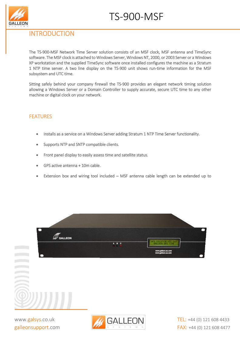
The TS-900-MSF Network Time Server solution consists of an MSF clock, MSF antenna and TimeSync software. The MSF clock is attached to Windows Server, Windows NT, 2000, or 2003 Server or a Windows XP workstation and the supplied TimeSync software once installed configures the machine as a Stratum 1 NTP time server. A two line display on the TS-900 unit shows run-time information for the MSF subsystem and UTC time.
Sitting safely behind your company firewall the TS-900 provides an elegant network timing solution allowing a Windows Server or a Domain Controller to supply accurate, secure UTC time to any other machine or digital clock on your network.
FEATURES
Installs as a service on a Windows Server adding Stratum 1 NTP Time Server functionality.
Supports NTP and SNTP compatible clients.
Front panel display to easily assess time and satellite status.
GPS active antenna + 10m cable.
Extension box and wiring tool included – MSF antenna cable length can be extended up to 1,000m (3,000ft) if required.
Syslog error reporting.
Email warning if MSF synchronisation is lost.
TS-900-MSF
www.galsys.co.uk
galleonsupport.com
TEL: +44 (0) 121 608 4433 FAX: +44 (0) 121 608 4477
WHAT SHOULD BE SHIPPED
STANDARD PARTS
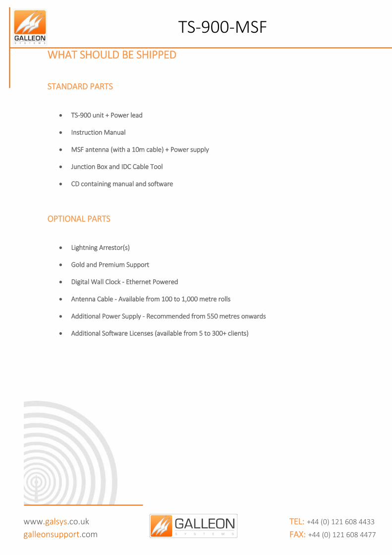
TS-900 unit + Power lead
Instruction Manual
MSF antenna (with a 10m cable) + Power supply
Junction Box and IDC Cable Tool
CD containing manual and software
OPTIONAL PARTS
Lightning Arrestor(s)
Gold and Premium Support
Digital Wall Clock - Ethernet Powered
Antenna Cable - Available from 100 to 1,000 metre rolls
Additional Power Supply - Recommended from 550 metres onwards
Additional Software Licenses (available from 5 to 300+ clients)

TS-900-MSF
www.galsys.co.uk
galleonsupport.com
TEL: +44 (0) 121 608 4433 FAX: +44 (0) 121 608 4477
TECHNICAL SPECIFICATION
Type of receiver MSF Radio Antenna Mounting (Unit) 19” (2U) Rackmount
Mounting (Antenna) Wall mounting bracket
Display LCD, 2 x 20 characters, with backlight
Network Interface Via a Windows server or workstation
Interface to Server RS232 serial interface Power supply 85 - 260V, 47 - 63Hz
Working Temperature 0 - 50°C / 32 - 122°F
Working Humidity Max. 85%
Timing Accuracy Network: +/- 20 milliseconds, typical GPS: 1 microseconds, relative to UTC
Signal (MSF) Accuracy <2 µs, relative to UTC
TS-900-MSF
www.galsys.co.uk
galleonsupport.com
TEL: +44 (0) 121 608 4433 FAX: +44 (0) 121 608 4477
SYSTEM OVERVIEW
TS-900-MSF
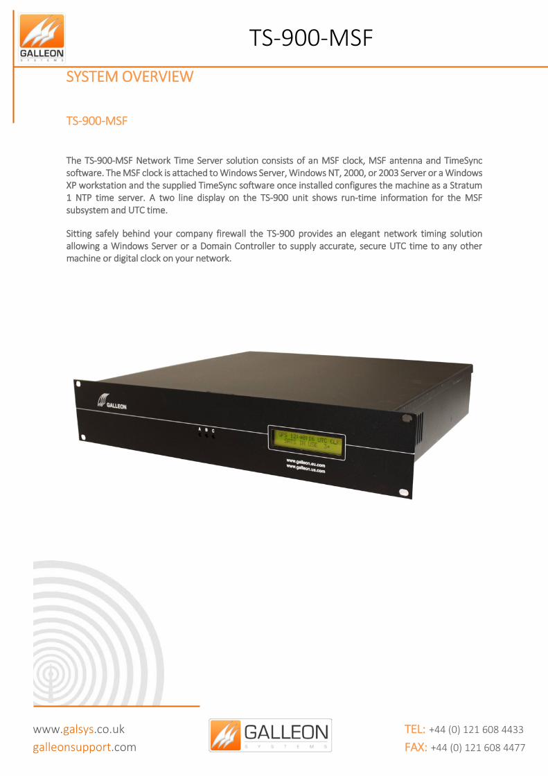
The TS-900-MSF Network Time Server solution consists of an MSF clock, MSF antenna and TimeSync software. The MSF clock is attached to Windows Server, Windows NT, 2000, or 2003 Server or a Windows XP workstation and the supplied TimeSync software once installed configures the machine as a Stratum 1 NTP time server. A two line display on the TS-900 unit shows run-time information for the MSF subsystem and UTC time.
Sitting safely behind your company firewall the TS-900 provides an elegant network timing solution allowing a Windows Server or a Domain Controller to supply accurate, secure UTC time to any other machine or digital clock on your network.
TS-900-MSF
www.galsys.co.uk
galleonsupport.com
TEL: +44 (0) 121 608 4433 FAX: +44 (0) 121 608 4477
MSF ANTENNA
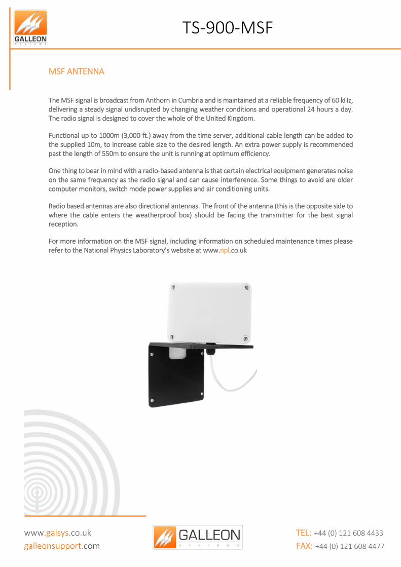
The MSF signal is broadcast from Anthorn in Cumbria and is maintained at a reliable frequency of 60 kHz, delivering a steady signal undisrupted by changing weather conditions and operational 24 hours a day. The radio signal is designed to cover the whole of the United Kingdom.
Functional up to 1000m (3,000 ft.) away from the time server, additional cable length can be added to the supplied 10m, to increase cable size to the desired length. An extra power supply is recommended past the length of 550m to ensure the unit is running at optimum efficiency.
One thing to bear in mind with a radio-based antenna is that certain electrical equipment generates noise on the same frequency as the radio signal and can cause interference. Some things to avoid are older computer monitors, switch mode power supplies and air conditioning units.
Radio based antennas are also directional antennas. The front of the antenna (this is the opposite side to where the cable enters the weatherproof box) should be facing the transmitter for the best signal reception.
For more information on the MSF signal, including information on scheduled maintenance times please refer to the National Physics Laboratory’s website at www.npl.co.uk

TS-900-MSF
www.galsys.co.uk
galleonsupport.com
TEL: +44 (0) 121 608 4433 FAX: +44 (0) 121 608 4477
DCF ANTENNA
The DCF antenna receives a radio signal broadcast at 77.5 kHz from Frankfurt (Main). The signal covers the whole of Germany and impressively most of Europe too.
Functional up to 1000m (3,000 ft.) away from the time server, additional cable length can be added to the supplied 10m to increase cable size to the desired length. An extra power supply is recommended past the length of 550m to ensure the unit is running at optimum efficiency.
One thing to bear in mind with a radio-based antenna is that certain electrical equipment generates noise on the same frequency as the radio signal and can cause interference. Some things to avoid are older computer monitors, switch mode power supplies and air conditioning units.
Radio based antennas are also directional antennas. The front of the antenna (this is the opposite side to where the cable enters the box) should be facing the transmitter for the best signal reception.
For more information on the DCF signal including information on scheduled maintenance times, please refer to the Physikalisch-Technische Bundesanstalt website at www.ptb.de English can be selected via the menu located at the top left side of the site.
There is an alternative website for information on the DCF signal, however, please note this website is provided only in German at www.dcf77.de
TS-900-MSF
www.galsys.co.uk
galleonsupport.com
TEL: +44 (0) 121 608 4433 FAX: +44 (0) 121 608 4477
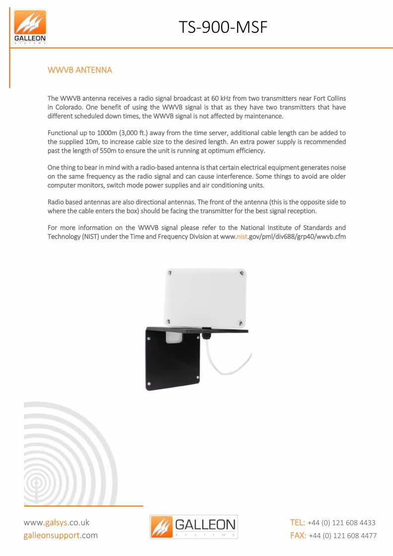
WWVB ANTENNA
The WWVB antenna receives a radio signal broadcast at 60 kHz from two transmitters near Fort Collins in Colorado. One benefit of using the WWVB signal is that as they have two transmitters that have different scheduled down times, the WWVB signal is not affected by maintenance.
Functional up to 1000m (3,000 ft.) away from the time server, additional cable length can be added to the supplied 10m, to increase cable size to the desired length. An extra power supply is recommended past the length of 550m to ensure the unit is running at optimum efficiency.
One thing to bear in mind with a radio-based antenna is that certain electrical equipment generates noise on the same frequency as the radio signal and can cause interference. Some things to avoid are older computer monitors, switch mode power supplies and air conditioning units.
Radio based antennas are also directional antennas. The front of the antenna (this is the opposite side to where the cable enters the box) should be facing the transmitter for the best signal reception.
For more information on the WWVB signal please refer to the National Institute of Standards and Technology (NIST) under the Time and Frequency Division at www.nist.gov/pml/div688/grp40/wwvb.cfm
TS-900-MSF
www.galsys.co.uk
galleonsupport.com
TEL: +44 (0) 121 608 4433 FAX: +44 (0) 121 608 4477
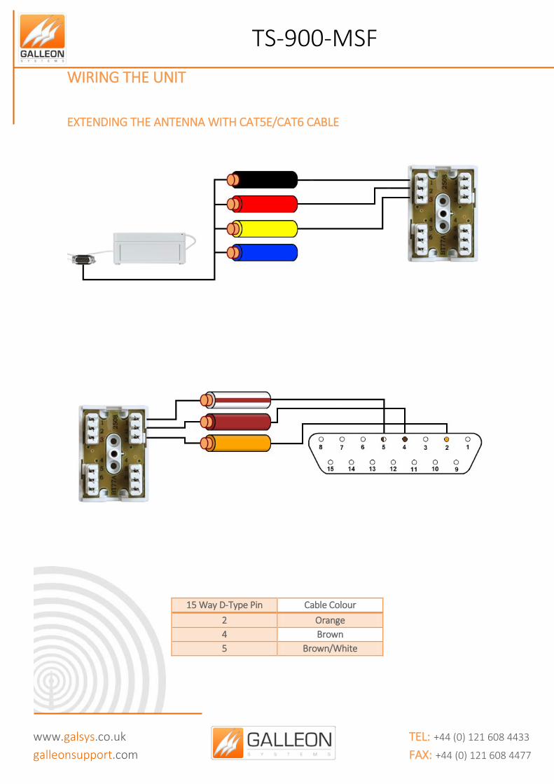
WIRING THE UNIT
EXTENDING THE ANTENNA WITH CAT5E/CAT6 CABLE
15 Way D-Type Pin Cable Colour
2 Orange
4 Brown
5 Brown/White

TS-900-MSF
www.galsys.co.uk
galleonsupport.com
TEL: +44 (0) 121 608 4433 FAX: +44 (0) 121 608 4477
EXTENDING THE ANTENNA WITH FOUR - CORE CABLE
15 Way D-Type Pin Cable Colour
2 Yellow
4 Red
5 Black
TS-900-MSF
www.galsys.co.uk
galleonsupport.com
TEL: +44 (0) 121 608 4433 FAX: +44 (0) 121 608 4477
SETTING UP THE UNIT
CONNECTING EVERYTHING UP
Server Location
Choose a suitable location for the TS-900-MSF; please bear in mind you will need to run a cable from this location preferably to the roof of the building or to a window.
Connect to Network
Connect the TS-900-MSF to a Computer via the Serial RS232 cable or the USB adapter cable. Connect the computer to the network using a standard RJ-45 cable.
Install Antenna
Choose an area to mount the Radio Antenna; the ideal place would be the roof of the building facing the correct Transmitter. Things to avoid are air conditioning units and power distribution units, as these will cause electrical interference.
Please note that if you are extending the cable to a length of 550m or greater, then you will need an extra power source, located either on the roof or can be accessed from the roof.
Connecting the Server to the Antenna
The cable should be run from the rack mount enclosure to the selected mounting position.
Please note that it is a good idea to leave some slack cable in case you need to move the unit later. Also the maximum cable length should not exceed 1000m.
TS-900-MSF
www.galsys.co.uk
galleonsupport.com
TEL: +44 (0) 121 608 4433 FAX: +44 (0) 121 608 4477
TROUBLESHOOTING
Use this section to quickly troubleshoot minor issues or common problems.
For any further support, please contact us using our Support Website, which can be found at:
galleonsupport.com
Q) The signal in the building is not adequate for the atomic clock. Is there anything that can be done to improve it?
A) We recommend that the antenna is placed outside the building preferably on the roof, in most cases the antenna will function inside of the building but often with limited signal strength.
Q) Can the cabling for the antenna be taken across the existing CAT5 cabling structure in our building?
A) Yes, the GPS antenna can be taken across CAT5 / UTP cabling, however, the cabling must be ‘point-to-point’ and cannot pass through routers, hubs, or switches.
Q) What type of cable should I use for extending the MSF antenna to 1000m?
A) The GPS antenna uses standard unscreened eight-core cable. In most cases, this is adequate; however, in some cases screened cable may be required.
Note: The cabling is often referred to as ‘eight-core alarm cable’.
TS-900-MSF
www.galsys.co.uk
galleonsupport.com
TEL: +44 (0) 121 608 4433 FAX: +44 (0) 121 608 4477
TECHNICAL SUPPORT
SUPPORT WEBSITE
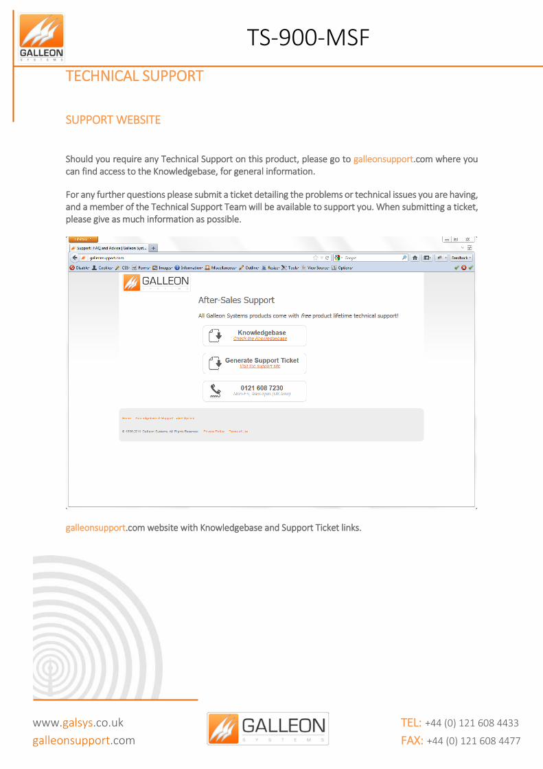
Should you require any Technical Support on this product, please go to galleonsupport.com where you can find access to the Knowledgebase, for general information.
For any further questions please submit a ticket detailing the problems or technical issues you are having, and a member of the Technical Support Team will be available to support you. When submitting a ticket, please give as much information as possible.
galleonsupport.com website with Knowledgebase and Support Ticket links.

TS-900-MSF
www.galsys.co.uk
galleonsupport.com
TEL: +44 (0) 121 608 4433 FAX: +44 (0) 121 608 4477
The Technical Support Knowledgebase.
The Technical Support Ticket System.

TS-900-MSF
www.galsys.co.uk
galleonsupport.com
TEL: +44 (0) 121 608 4433 FAX: +44 (0) 121 608 4477
WARRANTY AND MAINTENANCE
WARRANTY
Galleon Systems warrants the time server to be free from defects in material and workmanship during a three-year period. The Warranty begins on the date the unit is shipped from Galleon Systems. Extended warranties are available by speaking to the Galleon Systems Sales Team.
Galleon Systems’ liability under this Warranty is limited to repairing or replacing, at Galleon systems’ option, the defective equipment and providing upgrade version changes for firmware. In case of repair, the product must be returned to Galleon systems.
This Warranty does not apply if repairs are required due to acts of nature beyond Galleon systems’ control such as, but not limited to, lightning strikes, power surges, misuse, damage, neglect, or if repairs/modifications have been made or attempted by anyone other than personnel authorised by Galleon Systems.
In no event will Galleon Systems be liable for any indirect, special, incidental or consequential damages from the sale or use of this product.
This disclaimer applies both during and after the term of the warranty. Galleon Systems disclaims liability for any implied warranties, including implied warranties of merchantability and fitness for a specific purpose.
TECHNICAL SUPPORT, REPAIR AND RETURNS
To obtain any Technical Support with this product, contact Galleon Systems via the Support Website – galleonsupport.com
If throughout the Technical Support process it is deemed that you need to send any products back for repair, we will issue a Return Material Authorisation (RMA) Number and shipping instructions. Then ship the product, transportation prepaid, for inspection.
Typical Equipment repair or replacement time is five (5) business days, plus shipping times. One-way shipping is the customer’s responsibility. Galleon Systems will return ship the equipment by the same means it was received.
Galleon Systems will not be responsible for unauthorised returns or for returns that do not list the RMA Number on a packing list attached in plain view on the outside of the shipping container.