Embed Size (px)
Citation preview

ETSI TS 102 825-9 V1.2.1 (2011-02)
Technical Specification
Digital Video Broadcasting (DVB);Content Protection and Copy Management (DVB-CPCM);
Part 9: CPCM System Adaptation Layers
ETSI
ETSI TS 102 825-9 V1.2.1 (2011-02)2
Reference RTS/JTC-DVB-252-9
Keywords broadcast, DVB
ETSI
650 Route des Lucioles F-06921 Sophia Antipolis Cedex - FRANCE
Tel.: +33 4 92 94 42 00 Fax: +33 4 93 65 47 16
Siret N° 348 623 562 00017 - NAF 742 C
Association à but non lucratif enregistrée à la Sous-Préfecture de Grasse (06) N° 7803/88
Important notice
Individual copies of the present document can be downloaded from: http://www.etsi.org
The present document may be made available in more than one electronic version or in print. In any case of existing or perceived difference in contents between such versions, the reference version is the Portable Document Format (PDF).
In case of dispute, the reference shall be the printing on ETSI printers of the PDF version kept on a specific network drive within ETSI Secretariat.
Users of the present document should be aware that the document may be subject to revision or change of status. Information on the current status of this and other ETSI documents is available at
http://portal.etsi.org/tb/status/status.asp
If you find errors in the present document, please send your comment to one of the following services: http://portal.etsi.org/chaircor/ETSI_support.asp
Copyright Notification
No part may be reproduced except as authorized by written permission. The copyright and the foregoing restriction extend to reproduction in all media.
© European Telecommunications Standards Institute 2011.
© European Broadcasting Union 2011. All rights reserved.
DECTTM, PLUGTESTSTM, UMTSTM, TIPHONTM, the TIPHON logo and the ETSI logo are Trade Marks of ETSI registered
for the benefit of its Members. 3GPPTM is a Trade Mark of ETSI registered for the benefit of its Members and of the 3GPP Organizational Partners.
LTE™ is a Trade Mark of ETSI currently being registered for the benefit of its Members and of the 3GPP Organizational Partners.
GSM® and the GSM logo are Trade Marks registered and owned by the GSM Association.
ETSI
ETSI TS 102 825-9 V1.2.1 (2011-02)3
Contents
Intellectual Property Rights ................................................................................................................................ 5
Foreword ............................................................................................................................................................. 5
Introduction ........................................................................................................................................................ 5
1 Scope ........................................................................................................................................................ 6
2 References ................................................................................................................................................ 6
2.1 Normative references ......................................................................................................................................... 6
2.2 Informative references ........................................................................................................................................ 7
3 Definitions and abbreviations ................................................................................................................... 7
3.1 Definitions .......................................................................................................................................................... 7
3.2 Abbreviations ..................................................................................................................................................... 7
4 CPCM System Adaptations for Content Formats .................................................................................... 8
4.1 CPCM System Adaptation for MPEG-2 Transport Stream ................................................................................ 8
4.1.1 General .......................................................................................................................................................... 8
4.1.2 CPCM Content Scrambling for MPEG-2 TS ................................................................................................ 8
4.1.3 Embedded carriage of the CPCM Content Licence in MPEG-2 TS ............................................................. 8
4.1.4 Embedded carriage of the CPCM Auxiliary Data in MPEG-2 TS................................................................ 9
4.1.5 Embedded carriage of the CPCM delivery signalling in MPEG-2 TS .......................................................... 9
4.1.6 Content scrambling key change and synchronisation for MPEG-2 TS ......................................................... 9
4.1.7 Carriage of the CPCM Revocation List in MPEG-2 TS ............................................................................... 9
4.1.8 Multiple C&R regime ................................................................................................................................. 10
5 CPCM System Adaptations for Content Storage Formats ..................................................................... 10
5.1 General ............................................................................................................................................................. 10
5.2 CPCM System Adaptation for DVB File Format ............................................................................................. 10
5.2.1 General ........................................................................................................................................................ 10
5.2.2 Content Licence and Auxiliary Data Transport .......................................................................................... 10
5.2.3 CPCM adaptation to DVB-FF for MPEG2-TS ........................................................................................... 10
6 CPCM System adaptations for Home Network Ecosystems .................................................................. 11
6.1 CPCM System adaptation for DVB-HN .......................................................................................................... 11
6.1.1 General ........................................................................................................................................................ 11
6.1.2 Mapping of CPCM to UPnP ....................................................................................................................... 11
6.1.3 CPCM Instance Discovery .......................................................................................................................... 12
6.1.3.1 UPnP Service Definition for CPCM ..................................................................................................... 12
6.1.3.2 CPCM Instance Capabilities Discovery ................................................................................................ 12
6.1.4 Sending a message to other CPCM Instances via UPnP ............................................................................. 13
6.1.5 CPCM Content Discovery .......................................................................................................................... 13
6.1.6 CPCM Content Formats within DVB-HN .................................................................................................. 15
6.1.7 CPCM Propagation Tools for DVB-HN ..................................................................................................... 15
6.1.8 UPnP service definition .............................................................................................................................. 15
6.1.9 Theory of Operation.................................................................................................................................... 16
6.1.10 Revocation List Locator .............................................................................................................................. 17
6.2 CPCM System Adaptations for proximity tools ............................................................................................... 17
6.2.1 Proximity Tools for IP Networks ................................................................................................................ 17
6.2.1.1 Overview ............................................................................................................................................... 17
6.2.1.2 Round Trip Time (RTT) ........................................................................................................................ 18
6.2.1.3 Internet Datagram Header Time To Live (TTL) ................................................................................... 18
6.2.1.4 Secured Internet Datagram Header Time To Live (STTL) ................................................................... 19
6.2.1.4.1 General ............................................................................................................................................ 19
6.2.1.4.2 STTL Request .................................................................................................................................. 19
6.2.1.4.3 STTL Response ............................................................................................................................... 20
6.2.1.5 Combination of Secured RTT and Secured TTL (SRTTL) ................................................................... 20
6.2.1.5.1 General ............................................................................................................................................ 20
6.2.1.5.2 SRTTL Request ............................................................................................................................... 21
ETSI
ETSI TS 102 825-9 V1.2.1 (2011-02)4
6.2.1.5.3 SRTTL Response............................................................................................................................. 22
6.2.1.5.4 SRTTL Validation Request ............................................................................................................. 22
6.2.1.5.5 SRTTL Validation Response ........................................................................................................... 23
6.2.1.6 Network Topology Testing (NTT) ........................................................................................................ 24
7 CPCM System adaptations for application-specific physical interfaces ................................................ 24
7.1 CPCM System Adaptation for DVB Common Interface.................................................................................. 25
7.1.1 General ........................................................................................................................................................ 25
7.1.2 Additional Requirements for CPCM support .............................................................................................. 25
7.1.3 CPCM System Adaptation to DVB-CI ....................................................................................................... 25
7.1.4 Minimal CPCM Implementation for Protected Input Content Acquisition over DVB-CI .......................... 27
7.1.4.1 General .................................................................................................................................................. 27
7.1.4.2 CPCM Secure Data ............................................................................................................................... 27
7.1.4.3 CPCM LSA ........................................................................................................................................... 28
7.1.4.4 CPCM Protocols ................................................................................................................................... 28
7.1.4.5 CPCM Proximity Control ..................................................................................................................... 28
7.2 CPCM System Specification for ISO7816 Smart Card Interface ..................................................................... 28
7.2.1 General ........................................................................................................................................................ 28
7.2.2 ISO 7816 background ................................................................................................................................. 29
7.2.3 CPCM smart card APDU commands ............................................................................................................... 29
7.2.3.1 Overview .................................................................................................................................................... 29
7.2.3.2 send_message ............................................................................................................................................. 31
7.2.3.3 get_message ................................................................................................................................................ 32
7.2.3.4 CPCM smart cards Status Word ................................................................................................................. 33
7.2.4 Proximity Control ............................................................................................................................................. 33
7.2.4.1 Introduction................................................................................................................................................. 33
7.2.4.2 Overview .................................................................................................................................................... 33
7.2.4.3 PTDC for smart card interface .................................................................................................................... 33
7.2.4.3 SRTT support.............................................................................................................................................. 34
7.2.4.4 PTA support ................................................................................................................................................ 34
8 CPCM System adaptations for delivery networks .................................................................................. 34
8.1 DVB delivery adaptation layer ......................................................................................................................... 34
8.1.1 CPCM CLID allocation scheme ....................................................................................................................... 34
8.1.1.1 Introduction................................................................................................................................................. 34
8.1.1.2 DVB Broadcast Event and Acquisition Device .......................................................................................... 35
8.1.1.3 DVB broadcast service and Acquisition Device ......................................................................................... 35
8.1.1.4 CA system and Acquisition Device ............................................................................................................ 36
8.1.1.5 DVB-MHP application identifier and Acquisition Device ......................................................................... 36
8.2 IP delivery adaptation layer .............................................................................................................................. 36
8.2.1 SRM delivery over an IP network .................................................................................................................... 36
Annex A (informative): Bibliography ................................................................................................... 37
History .............................................................................................................................................................. 40
ETSI
ETSI TS 102 825-9 V1.2.1 (2011-02)5
Intellectual Property Rights IPRs essential or potentially essential to the present document may have been declared to ETSI. The information pertaining to these essential IPRs, if any, is publicly available for ETSI members and non-members, and can be found in ETSI SR 000 314: "Intellectual Property Rights (IPRs); Essential, or potentially Essential, IPRs notified to ETSI in respect of ETSI standards", which is available from the ETSI Secretariat. Latest updates are available on the ETSI Web server (http://webapp.etsi.org/IPR/home.asp).
Pursuant to the ETSI IPR Policy, no investigation, including IPR searches, has been carried out by ETSI. No guarantee can be given as to the existence of other IPRs not referenced in ETSI SR 000 314 (or the updates on the ETSI Web server) which are, or may be, or may become, essential to the present document.
Foreword This Technical Specification (TS) has been produced by Joint Technical Committee (JTC) Broadcast of the European Broadcasting Union (EBU), Comité Européen de Normalisation ELECtrotechnique (CENELEC) and the European Telecommunications Standards Institute (ETSI).
NOTE: The EBU/ETSI JTC Broadcast was established in 1990 to co-ordinate the drafting of standards in the specific field of broadcasting and related fields. Since 1995 the JTC Broadcast became a tripartite body by including in the Memorandum of Understanding also CENELEC, which is responsible for the standardization of radio and television receivers. The EBU is a professional association of broadcasting organizations whose work includes the co-ordination of its members' activities in the technical, legal, programme-making and programme-exchange domains. The EBU has active members in about 60 countries in the European broadcasting area; its headquarters is in Geneva.
European Broadcasting Union CH-1218 GRAND SACONNEX (Geneva) Switzerland Tel: +41 22 717 21 11 Fax: +41 22 717 24 81
The Digital Video Broadcasting Project (DVB) is an industry-led consortium of broadcasters, manufacturers, network operators, software developers, regulatory bodies, content owners and others committed to designing global standards for the delivery of digital television and data services. DVB fosters market driven solutions that meet the needs and economic circumstances of broadcast industry stakeholders and consumers. DVB standards cover all aspects of digital television from transmission through interfacing, conditional access and interactivity for digital video, audio and data. The consortium came together in 1993 to provide global standardisation, interoperability and future proof specifications.
The present document is part 9 of a multi-part deliverable. Full details of the entire series can be found in part 1 [8].
Introduction CPCM is a system for Content Protection and Copy Management of commercial digital content delivered to consumer products. CPCM manages content usage from acquisition into the CPCM system until final consumption, or export from the CPCM system, in accordance with the particular usage rules of that content. Possible sources for commercial digital content include broadcast (e.g. cable, satellite, and terrestrial), Internet-based services, packaged media, and mobile services, among others. CPCM is intended for use in protecting all types of content - audio, video and associated applications and data. CPCM specifications facilitate interoperability of such content after acquisition into CPCM by networked consumer devices for both home networking and remote access.
This first phase of the specification addresses CPCM for digital Content encoded and transported by linear transport systems in accordance with TS 101 154 [1]. A later second phase will address CPCM for Content encoded and transported by systems that are based upon Internet Protocols in accordance with TS 102 005 [i.1].
ETSI
ETSI TS 102 825-9 V1.2.1 (2011-02)6
1 Scope The present document contains normative specifications for the Adaptation Layers between Digital Video Broadcasting (DVB) Content Protection and Copy Management (CPCM) system and underlying technologies.
CPCM Phase 1 includes the adaptation layer for content carried inside an MPEG-2 transport stream (TS) (see TS 101 154 [1]) specified in clause 4.1.
2 References References are either specific (identified by date of publication and/or edition number or version number) or non-specific. For specific references, only the cited version applies. For non-specific references, the latest version of the reference document (including any amendments) applies.
Referenced documents which are not found to be publicly available in the expected location might be found at http://docbox.etsi.org/Reference.
NOTE: While any hyperlinks included in this clause were valid at the time of publication ETSI cannot guarantee their long term validity.
2.1 Normative references The following referenced documents are necessary for the application of the present document.
[1] ETSI TS 101 154: "Digital Video Broadcasting (DVB); Specification for the use of Video and Audio Coding in Broadcasting Applications based on the MPEG-2 Transport Stream".
[2] ETSI EN 300 468: "Digital Video Broadcasting (DVB); Specification for Service Information (SI) in DVB Systems".
[3] ETSI TS 102 905: "Digital Video Broadcasting (DVB); Technical Specification for DVB Services in the Home Network Phase 1".
[4] CENELEC EN 50221: "Common interface specification for conditional access and other digital video broadcasting decoder applications".
[5] ETSI TS 101 699 (V1.1.1): "Digital Video Broadcasting (DVB); Extensions to the Common Interface Specification".
[6] ISO/IEC 7816-4 (2005): "Identification cards - Integrated circuit cards - Part 4: Organization, security and commands for interchange".
[7] IETF RFC 791: "Internet Protocol (IP)".
[8] ETSI TS 102 825-1: "Digital Video Broadcasting (DVB); Content Protection and Copy Management (DVB-CPCM); Part 1: CPCM Abbreviations, Definitions and Terms".
[9] ETSI TS 102 825-4: "Digital Video Broadcasting (DVB); Content Protection and Copy Management (DVB-CPCM); Part 4: CPCM System Specification".
[10] ETSI TS 102 825-5: "Digital Video Broadcasting (DVB); Content Protection and Copy Management (DVB-CPCM); Part 5: CPCM Security Toolbox".
[11] IETF RFC 792: "Internet Control Message Protocol".
[12] ETSI TS 102 833: "Digital Video Broadcasting (DVB); File Format Specification for the Storage and Playback of DVB Services".
[13] ETSI TS 102 034: "Digital Video Broadcasting (DVB); Transport of MPEG-2 TS Based DVB Services over IP Based Networks".
ETSI
ETSI TS 102 825-9 V1.2.1 (2011-02)7
[14] ISO/IEC 14496-12 (2008): "Information Technology - Coding of audio-visual objects - Part 12: ISO base media file format", third edition.
[15] ISO/IEC 7816-1 (1998): "Identification cards - Integrated circuit(s) cards with contacts - Part 1: Physical characteristics".
[16] ISO/IEC 7816-2 (2007): "Identification cards - Integrated circuit cards - Part 2: Cards with contacts -- Dimensions and location of the contacts".
[17] ISO/IEC 7816-3 (2006): "Identification cards - Integrated circuit cards - Part 3: Cards with contacts -- Electrical interface and transmission protocols".
[18] ISO/IEC 14443-1 (2008): "Identification cards - Contactless integrated circuit cards - Proximity cards - Part 1: Physical characteristics".
[19] ISO/IEC 14443-2 (2001): "Identification cards - Contactless integrated circuit(s) cards - Proximity cards - Part 2: Radio frequency power and signal interface".
[20] ISO/IEC 14443-3 (2001): "Identification cards - Contactless integrated circuit(s) cards - Proximity cards - Part 3: Initialization and anticollision".
[21] ISO/IEC 14443-4 (2008): "Identification cards - Contactless integrated circuit cards - Proximity cards - Part 4: Transmission protocol".
2.2 Informative references The following referenced documents are not necessary for the application of the present document but they assist the user with regard to a particular subject area.
[i.1] ETSI TS 102 005: "Digital Video Broadcasting (DVB); Specification for the use of Video and Audio Coding in DVB services delivered directly over IP protocols".
[i.2] ETSI TS 101 162: "Digital Video Broadcasting (DVB); Allocation of identifiers and codes for Digital Video Broadcasting (DVB) systems".
[i.3] ETSI TR 102 825-12: "Digital Video Broadcasting (DVB); Content Protection and Copy Management (DVB-CPCM); Part 12: CPCM Implementation Guidelines".
3 Definitions and abbreviations
3.1 Definitions For the purposes of the present document, the terms and definitions given in TS 102 825-1 [8] apply.
3.2 Abbreviations For the purposes of the present document, the abbreviations given in TS 102 825-1 [8] apply.
ETSI
ETSI TS 102 825-9 V1.2.1 (2011-02)8
4 CPCM System Adaptations for Content Formats
4.1 CPCM System Adaptation for MPEG-2 Transport Stream
4.1.1 General
This clause specifies the adaptation layer of the CPCM System for handling of CPCM Content (C.0) in the form of the MPEG-2 Transport Stream, defined in TS 101 154 [1].
The CPCM System does not specify the content formats carried within the MPEG-2 Transport Stream. These are defined, if at all, in the adaptation layers of the respective home network ecosystems (see TS 102 905 [3]) and application-specific physical interfaces. Otherwise the contents of the TS may be anything that is compliant with TS 101 154 [1].
The following aspects are specified in the subsequent clauses:
• CPCM Content scrambling for MPEG-2 TS.
• Embedded carriage of the CPCM protocol message containing the CPCM Content Licence (CL) in MPEG-2 TS.
• Embedded carriage of the CPCM Auxiliary Data in MPEG-2 TS.
• Content scrambling key change and synchronisation for MPEG-2 TS.
• Carriage of the CPCM Revocation List in MPEG-2 TS.
4.1.2 CPCM Content Scrambling for MPEG-2 TS
The CPCM Security Toolbox specification (TS 102 825-5 [10]) defines the application of the CPCM Scrambling Tool to an MPEG-2 Transport Stream that is to be scrambled within the CPCM System.
The CPCM Acquisition Point shall ensure that the value of scrambling_control_bits in the MPEG2-TS header of the CPCM Content Item is consistent with the setting of the odd_even_key_indicator bit in the CPCM_descrambler_information field within the CPCM Content Licence, as specified in TS 102 825-4 [9]. The settings are shown in table 1. This might require a change in the MPEG2-TS header.
Table 1: Application of TS header scrambling control bits
Bit values Description 00 No scrambling of TS packet payload (MPEG-2 compliant) 01 Reserved for future DVB use 10 TS packet scrambled with Even Key 11 TS packet scrambled with Odd Key
If the corresponding Input Content applies different settings of the MPEG-2 TS header scrambling_control_bits, for example if crypto-periods are applied then these bits will be continually changing, the Acquisition Point shall change these settings in the TS header in order to comply with the CPCM settings as described.
4.1.3 Embedded carriage of the CPCM Content Licence in MPEG-2 TS
The CPCM Content Licence (CL) shall be carried (embedded) within the (partial) TS that constitutes a CPCM Content Item, by the following means:
• For each service which is part of a CPCM Content Item, the corresponding PMT shall indicate the location of the CPCM Content Licence by means of a CP_descriptor indicating a CP_system_id allocated in TS 101 162 [i.2] to DVB CPCM for CL carriage. The CP_descriptor is specified in EN 300 468 [2].
• The CP_descriptor shall reference a PID where any protocol message that contains the CL will be found.
ETSI
ETSI TS 102 825-9 V1.2.1 (2011-02)9
When the Content Licence is SAC protected, the entire CPCM message, except for the CPCM Auxiliary Data, shall be carried at that location. When the Content Licence is only AD protected, only the Content Licence shall be carried at that location.
4.1.4 Embedded carriage of the CPCM Auxiliary Data in MPEG-2 TS
The CPCM Auxiliary Data, if present for the associated Content Item, shall be carried (embedded) within the (partial) TS that constitutes a CPCM Content Item, by the following means:
• For each service which is part of a CPCM Content Item, the corresponding PMT shall indicate the location of the CPCM Auxiliary Data by means of a CP_descriptor indicating a CP_system_id allocated in TS 101 162 [i.2] to DVB CPCM for Auxiliary Data carriage. The CP_descriptor is specified in EN 300 468 [2].
• The CP_descriptor shall reference a PID where the Auxiliary Data will be found.
Whatever is the Content Licence protection mode, the Auxiliary Data shall always be carried at that location.
4.1.5 Embedded carriage of the CPCM delivery signalling in MPEG-2 TS
The CPCM delivery signalling shall be carried (embedded) within the (partial) TS that constitutes a CPCM Content Item, using cpcm_delivery_signalling_descriptor depicted in table 2. This descriptor is an extended descriptor as defined in EN 300 468 [2] that allocates the corresponding extension tag.
Table 2: CPCM delivery signalling descriptor
Syntax Number of bits Identifier cpcm_delivery_signalling_descriptor(){ cpcm_version 8 bslbf for (i=0; i<N; i++){ selector_byte 8 }
Semantics for the CPCM delivery signalling descriptor:
cpcm_version: This 8-bit field indicates the encoding version of the CPCM USI data structure conveyed in the selector bytes following. The current version number is defined in TS 102 825-4 [9].
selector_byte: This is an 8-bit field. The sequence of selector_byte fields specifies the selector field. The syntax and semantics of the selector field shall be coded according to the encoding version indicated by the cpcm_version field. The relevant syntax is described in TS 102 825-4 [9].
4.1.6 Content scrambling key change and synchronisation for MPEG-2 TS
The generic scenario for the forcing of a change of the CPCM Content Item scrambling key is specified in TS 102 825-4 [9]. This clause specifies the mapping of that procedure to an MPEG-2 TS.
For MPEG-2 TS the application of the odd and even content scrambling keys is signalled using the scrambling_control bits in the TS header, as specified in TS 101 154 [1].
4.1.7 Carriage of the CPCM Revocation List in MPEG-2 TS
The DVB SI specification (EN 300 468 [2]) specifies a method for the carriage of the CPCM Revocation List in MPEG-2 TS.
In addition, for CPCM revocation list carriage, the CP_descriptor may embed the applicable C&R regime.
ETSI
ETSI TS 102 825-9 V1.2.1 (2011-02)10
4.1.8 Multiple C&R regime
In the case where content is made available to several C&R regime, several Content Licences, Auxiliary Data or CPCM delivery signalling may be in-band with the content.
In this case, scope of the CP_descriptor of of the CPCM_delivery_signalling descriptor shall apply as described in EN 300 468 [2] per C&R regime identifier.
5 CPCM System Adaptations for Content Storage Formats
5.1 General This normative part of the CPCM System Specification contains specifications of how specific content storage formats are utilised within the CPCM System to enable the Storage of CPCM Content.
The only storage container identified to date is the DVB File Format (DVB-FF).
5.2 CPCM System Adaptation for DVB File Format
5.2.1 General
DVB-FF (TS 102 833 [12]) specifies the File Format used to store and playback DVB services. It is built on top of ISO base media file format (ISO/IEC 14496-12:2008 [14]). It also defines how to store and playback CPCM content within a DVB File.
CPCM conformant implementations shall conform to the DVB-FF specification.
NOTE: This adaptation layer is independent of the CPCM adaptation to the specific content format, which is performed as specified in clause 4.
5.2.2 Content Licence and Auxiliary Data Transport
The CPCM Content Licence and associated Auxiliary Data, if any, can be carried out-of-band or in-band with the content.
When the Content Licence and associated Auxiliary Data are carried out-of-band, they shall be inserted in the scheme information box 'schi' with:
• sub-box 'clic' for a CPCM Content License; and
• sub-box 'caux' for CPCM Auxiliary Data, if present.
When the Content Licence and associated Auxiliary Data are carried in-band, it is recommended, but not mandatory, to insert them in the scheme information box 'schi' as described above.
NOTE: However, the content is still marked as CPCM protected via the use of the 'pm2t' and the presence of the 'schm' box containing the 'cpcm' scheme specifier.
5.2.3 CPCM adaptation to DVB-FF for MPEG2-TS
Storage of CPCM MPEG2-TS content protected as described in clause 4.1.2 shall be performed as described in TS 102 833 [12], with the following additional constrains:
• In the file type box 'ftyp', the minor_version field shall be set to = x*256 + y for x.y.z version of the DVB FF specification TS 102 833 [12].
ETSI
ETSI TS 102 825-9 V1.2.1 (2011-02)11
EXAMPLE: For TS 102 833 (V1.1.1) [12], the minor_version filed shall be set to 1 * 256 + 1.
• The 'pm2t' sample entry shall include a protection scheme information box 'sinf'.
It is required to use protected track type 'pm2t' rather than 'rm2t' even in case of DNCS-marked CPCM Content, because the 'sinf' box is a sub-box of 'pm2t' and is needed to carry the Content License.
6 CPCM System adaptations for Home Network Ecosystems
This clause of the CPCM System Specification contains normative specifications of how the generic CPCM System tools and resources are adapted to particular home network ecosystems so that CPCM can work within that particular ecosystem.
The API between the CPCM Instance and the CPCM Network Adaptation Layer is most of the time informative as it is internal to a CPCM Device. If the CPCM Network Adaptation Layer is located in a separate device (e.g. this is the case for an ISO/IEC 7816-4 [6] smart card), the API is normative.
CPCM Phase 1 includes the adaptation layer for the DVB-HN home network ecosystem (see TS 102 905 [3]), specified in clause 6.1.
6.1 CPCM System adaptation for DVB-HN
6.1.1 General
This clause specifies the adaptation layer of the CPCM System for the Home Network ecosystem as specified by DVB (DVB-HN) in TS 102 905 [3].
DVB-HN is built on top of the UPnP networking layer. UPnP provides the tools to discover UPnP devices and services on the network, and to exchange messages between UPnP entities.
CPCM is implemented within DVB-HN by the definition of the following elements:
• A new UPnP Service is defined, namely the DVB-CPCM UPnP Service, that enables the exposure of CPCM System functionality of a device in a manner compliant with UPnP. The DVB-CPCM UPnP Service is defined in clause 6.1.3.
• An extension to the content attributes defined for DVB-HN that adds all CPCM-specific attributes that are relevant for the discovery of CPCM Content Items able to be served by any CPCM Device. This element is defined in clause 6.1.5.
• The specification of CPCM Proximity Tools that shall be deployed in applicable CPCM Devices. These are specified in clause 6.1.7.
In addition to the normative specification of these elements, the next clause first provides some background that is intended to help in understanding how CPCM maps to the UPnP-based home network ecosystem of DVB-HN.
6.1.2 Mapping of CPCM to UPnP
This clause contains the mapping of the CPCM System to UPnP, being the basis of DVB-HN.
CPCM does not define any specific device classes, so rather than there being a direct mapping from the UPnP device categories of Control Point, Media Server and Media Renderer, there are various logical mappings when considering devices.
Any CPCM Device that implements a CPCM Content Handling Functional Entity of an AP, SE or PE shall be considered to be a UPnP Media Server.
ETSI
ETSI TS 102 825-9 V1.2.1 (2011-02)12
Any CPCM Device that implements a CPCM Content Handling Functional Entity of a CP or EP shall be considered to be a UPnP Media Renderer.
The UPnP Control Point does not map to any CPCM-specific functionality, as it is totally within the realm of the "Device Application", as defined in the CPCM Reference Model. The UPnP Control Point does not need any additional functionality to work with CPCM as CPCM is transparent with respect to UPnP content usage functionality.
Any DVB-HN device that is CPCM-capable implements the DVB-CPCM UPnP Service in order to make CPCM System functionality available within the DVB-HN ecosystem.
6.1.3 CPCM Instance Discovery
In order to discover the CPCM Instance on the network, the CPCM Instance is represented as a UPnP Service.
6.1.3.1 UPnP Service Definition for CPCM
In the UPnP device description XML document, a service shall be defined as:
<service> <serviceType>urn:schemas-UPnP-org:service:serviceType:v</serviceType> <serviceId>urn:UPnP-org:serviceId:serviceID</serviceId> <SCPDURL>URL to service description</SCPDURL> <controlURL>URL for control</controlURL> <eventSubURL>URL for eventing</eventSubURL> </service>
Since the UPnP CPCM service belongs to the DVB domain name, it shall be defined as the following:
<serviceType>urn:schemas-dvb-org:service:CPCM:v</serviceType> <serviceId>urn:dvb-org:serviceId:CPCM_xx</serviceId>
NOTE 1: v represents the version of the UPnP service and is be equal to the CPCM version.
NOTE 2: xx is the extended instance identifier of the CPCM entity, to be defined as a hexadecimal sequence. This string reflects the concatenation of the CP System ID (16 bits) as defined in EN 300 468 [2] and the CPCM Instance Certificate (64 bits) identifier as defined in TS 102 825-4 [9], in hexadecimal values. For example, a CP System ID of "0x0000" and a CIC of "0x1234567890ABCDEF" will be represented by a serviceID of "urn:dvb-org:serviceId:CPCM_00001234567890ABCDEF".
NOTE 3: The CP System ID and CIC are set here because it simplifies the mapping between the CPCM layer and the DVB-HN layer.
NOTE 4: The maximum length for a ServiceId suffix (i.e. the part after "serviceId:" is 64 characters. The serviceId as defined here is "CPCM_" plus 80 bits encoded in hex, resulting in 25 characters.
6.1.3.2 CPCM Instance Capabilities Discovery
A CPCM Instance can expose the following capabilities information:
• The list of other CP System IDs that it can get content from in order to inject them into the CPCM realm.
• The list of other CP System IDs that it can send content to.
Those capabilities are discovered using the CPCM::GetCapabilities action.
Table 3: DVB-CPCM::GetCapabilities()
Argument Direction Related State Variable FromCPSystemID OUT A_ARG_TYPE_CPSystemIDList
ToCPSystemID OUT A_ARG_TYPE_CPSystemIDList
The A_ARG_TYPE_CPSystemIDList is a CSV (Comma Separated Value) list of CPSystemID encoded as with the bin.hex format, i.e. hexadecimal digits representing octets (1 binary octet is encoded as 2 ASCII characters).
ETSI
ETSI TS 102 825-9 V1.2.1 (2011-02)13
EXAMPLE: "1234,ABCD,9876" is holding three CP System IDs, 0x1234, 0xABCD and 0x9876.
6.1.4 Sending a message to other CPCM Instances via UPnP
To send a CPCM message to another CPCM Instance, a CPCM Instance shall form the message and then pass it to its CPCM Network Adaptation Layer together with the CPCM Instance Certificate Identifier of the destination CPCM Instance (if applicable, i.e. not for broadcast messages). The CPCM Network Adaptation Layer shall be responsible for sending the message to right destination.
The destination CPCM Network Adaptation Layer of the destination CPCM Instance receives the CPCM message and shall pass it to the relevant CPCM Instance together with the CPCM Instance Certificate Identifier of the sending CPCM Instance.
To send a message to another CPCM Instance, the UPnP service shall use the simple container API defined in table 4.
Table 4: DVB-CPCM::SendMessage()
Argument Direction Related State Variable SourceCpcmIdentifier IN A_ARG_TYPE_CpcmIdentifier
CpcmPayload IN A_ARG_TYPE_CpcmPayload
NOTE 1: This very simple method, will allow the DVB-HN NAL to cope with future extensions of the DVB-CPCM protocol with no modification.
NOTE 2: The SourceCpcmIdentifier is needed because with UPnP there is no way to know which UPnP entity is the sender of the message, or even if it comes from a non UPnP entity. A destination UPnP service only knows the IP address and TCP port of the sender. So in order for the receiving UPnP service to be able to provide this information to its CPCM Instance, it has to be set explicitly in the message.
Standard UPnP error handling shall be used as defined in table 5, please see TR 102 825-12 [i.3] for more detail.
Table 5: UPnP Error messages
errorCode errorDescription Description 402 Invalid Arguments (args) Could be any of the following: not enough in args, too many in args, no in arg
by that name, one or more in args are of the wrong data type. 501 Action Failed May be returned in current state of service prevents invoking that action. 600 Argument value invalid [IPI2399r3] Unknown CpcmIdentifier, or unknown
RevocationListIdentifier
Broadcast messages shall be performed by sending as many unicast messages as needed to all CPCM UPnP Services on the network.
6.1.5 CPCM Content Discovery
In DVB-HN the content is discovered thanks to the Content Directory Service (CDS) of the UPnP Media Server device. The content is represented as an item structured as an XML fragment. CPCM specific properties are added to this XML fragment with the following parameters:
• The Instance ID of the CPCM Instance that is in charge of this content: this is the CP System ID + CIC hexa string as specified in the service id parameter.
• The Content License Identifier (CLID): this is the 128 bits identifier as defined in TS 102 825-4 [9].
• The Content License Protection Mode: it can be Authorized domain (AD), Secure Authenticated Channel (SAC), or both. It shall have at least one of both.
• The Content License Transport Mode: it can be in-band,out-band, or both. CPCM Instances shall signal at least one mode for each Content Item.
ETSI
ETSI TS 102 825-9 V1.2.1 (2011-02)14
All those parameters are included in a new XML element to be integrated in the <item> structure. The schema of this new element is the following:
<?xml version="1.0" encoding="UTF-8"?> <xs:schema xmlns:xs="http://www.w3.org/2001/XMLSchema"> <xs:element name="CPCM"> <xs:complexType> <xs:sequence> <xs:element name="CPCMVersion" type="xs:unsignedInt"> </xs:element> <xs:element name="CPCMInstanceID"> <xs:simpleType> <xs:restriction base="xs:string"> <xs:pattern value="[0 9a fA F]{20}"/> </xs:restriction> </xs:simpleType> </xs:element> <xs:element name="CLID"> <xs:simpleType> <xs:restriction base="xs:string"> <xs:pattern value="[0 9a fA F]{32}"/> </xs:restriction> </xs:simpleType> </xs:element> <xs:element name="CLProtectionMode"> <xs:complexType> <xs:attribute name="AD" type="xs:boolean" use="required"/> <xs:attribute name="SAC" type=" xs:boolean " use=" required "/> </xs:complexType> </xs:element> <xs:element name="CLTransportMode"> <xs:complexType> <xs:attribute name="InBand" type="xs:boolean" use="required"/> <xs:attribute name="OutBand" type=" xs:boolean " use=" required "/> </xs:complexType> </xs:element> </xs:sequence> </xs:complexType> </xs:element> </xs:schema>
If a content item is available through multiple CPCM instances, a CPCM element shall be included inside the item element for each CPCM instance through which the content item is available.
Furthermore, the following parameters shall be filled:
• The "protection" attribute of the "res" element shall contain the value "xx.cpcm1.dvb.org" where xx is the extended identifier (as defined in clause 6.1.3.1) of the CPCM instance through which this resource is available;
• The fourth field of the "protocolInfo" attribute of the "res" element shall contain the UPnP-domain variable "upnp.org_DRMInfo" set to "cpcm1.dvb.org".
NOTE: Only the CPCM version given in the "CPCMVersion" attribute is considered to be the authoritative value for the CPCM version associated with the content.
In case of inconsistency between the fourth field of the protocolInfo attribute and the "protection" attribute of the "res" element the order of precedence is (highest first):
1) The "protection" attribute of the "res" element.
2) The "upnp.org_DRMInfo" of the fourth field of the protocolInfo attribute.
EXAMPLE: This is an example XML doc of an item protected thanks to CPCM system.
<item id="8" parentID="3" restricted="0"> <dc:title>SportsChannel</dc:title> <upnp:class>object.item.videoItem.videoBroadcast</upnp:class> <dvb:CPCM> <CPCMVersion>1</CPCMVersion> <CPCMInstanceId>00001234567890ABCDEF</CPCMInstanceID> <CLID>1234567890ABCDEF1234567890ABCDEF</CLID> <CLProtectionMode AD="true" SAC="false"/> <CLTransportMode InBand="false" OutBand="true"/>
ETSI
ETSI TS 102 825-9 V1.2.1 (2011-02)15
</dvb:CPCM> <tva:AVAttributes> ... </tva:AVAttributes> <res protection="00001234567890ABCDEF.cpcm1.dvb.org" protocolInfo="dvb-igmp:*:video/mpeg: DLNA.ORG_PN=MPEG_TS_SD_EU_ISO;upnp.org_DRMInfo=cpcm1.dvb.org"> dvb-mcast://227.0.0.1:12345?payload=mp2t/rtp&dvb-service=1111:2222:3333 </res> </item>
6.1.6 CPCM Content Formats within DVB-HN
The CPCM System does not define the media formats, these are however defined in TS 102 005 [i.1].
6.1.7 CPCM Propagation Tools for DVB-HN
This clause contains the normative specification of the network technology-specific CPCM propagation control tools for the DVB-HN ecosystem.
The propagation tools for CPCM in the context of DVB-HN shall include the following, the detailed parameters of which will be defined by the C&R regime:
• SRTT - For Content exchange between two CPCM Devices.
• RTT - For Content exchange between a CPCM Device and a non-CPCM device.
The following tools may be included at the discretion of the C&R regime:
• NTT
• TTL - To be applied to each packet of CPCM Content
• STTL
• SRTTL
• Other tools to be defined by the C&R regime.
These tools are detailed in clause 6.2.
6.1.8 UPnP service definition
The DVB CPCM service shall be defined using the following XML:
<?xml version="1.0"?> <scpd xmlns="urn:schemas-UPnP-org:service-1-0"> <specVersion> <major>1</major> <minor>0</minor> </specVersion> <actionList> <action> <name>GetCapabilities</name> <argumentList> <argument> <name>FromCPSystemID</name> <direction>out</direction> <relatedStateVariable>A_ARG_TYPE_CPSystemIDList</relatedStateVariable> </argument> <argument> <name>ToCPSystemID</name> <direction>out</direction> <relatedStateVariable>A_ARG_TYPE_CPSystemIDList</relatedStateVariable> </argument> </argumentList> </action> <action> <name>SendMessage</name> <argumentList> <argument>
ETSI
ETSI TS 102 825-9 V1.2.1 (2011-02)16
<name>SourceCpcmIdentifier</name> <direction>in</direction> <relatedStateVariable>A_ARG_TYPE_CpcmIdentifier</relatedStateVariable> </argument> <argument> <name>CpcmPayload</name> <direction>in</direction> <relatedStateVariable>A_ARG_TYPE_CpcmPayload</relatedStateVariable> </argument> </argumentList> </action> </actionList> <serviceStateTable> <stateVariable sendEvents="no"> <name>A_ARG_TYPE_CPSystemIdList</name> <dataType>string</dataType> </stateVariable> <stateVariable sendEvents="no"> <name>A_ARG_TYPE_CpcmIdentifier</name> <dataType>bin.hex</dataType> </stateVariable> <stateVariable sendEvents="no"> <name>A_ARG_TYPE_CpcmPayload</name> <dataType>bin.hex</dataType> </stateVariable> </serviceStateTable> </scpd>
6.1.9 Theory of Operation
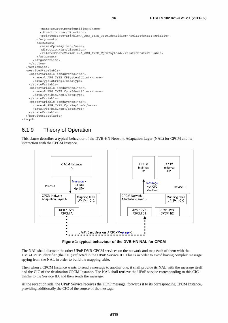
This clause describes a typical behaviour of the DVB-HN Network Adaptation Layer (NAL) for CPCM and its interaction with the CPCM Instance.
Figure 1: typical behaviour of the DVB-HN NAL for CPCM
The NAL shall discover the other UPnP DVB-CPCM services on the network and map each of them with the DVB-CPCM identifier (the CIC) reflected in the UPnP Service ID. This is in order to avoid having complex message spying from the NAL in order to build the mapping table.
Then when a CPCM Instance wants to send a message to another one, it shall provide its NAL with the message itself and the CIC of the destination CPCM Instance. The NAL shall retrieve the UPnP service corresponding to this CIC thanks to the Service ID, and then sends the message.
At the reception side, the UPnP Service receives the UPnP message, forwards it to its corresponding CPCM Instance, providing additionally the CIC of the source of the message.
ETSI
ETSI TS 102 825-9 V1.2.1 (2011-02)17
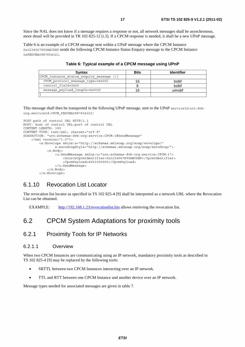
Since the NAL does not know if a message requires a response or not, all network messages shall be asynchronous, more detail will be provided in TR 102 825-12 [i.3]. If a CPCM response is needed, it shall be a new UPnP message.
Table 6 is an example of a CPCM message sent within a UPnP message where the CPCM Instance 0x1234567890ABCDEF sends the following CPCM Instance Status Enquiry message to the CPCM Instance 0xFEDCBA0987654321.
Table 6: Typical example of a CPCM message using UPnP
Syntax Bits Identifier CPCM_instance_status_enquiry_message (){ CPCM_protocol_message_type=0x4001 16 bslbf control_field=0x00 8 bslbf message_payload_length=0x0000 16 uimsbf }
This message shall then be transported in the following UPnP message, sent to the UPnP serviceId urn:dvb-org:serviceId:CPCM_FEDCBA0987654321:
POST path of control URL HTTP/1.1 HOST: host of control URL:port of control URL CONTENT-LENGTH: 399 CONTENT-TYPE: text/xml; charset="utf-8" SOAPACTION: "urn:schemas-dvb-org:service:CPCM:1#SendMessage" <?xml version="1.0"?> <s:Envelope xmlns:s="http://schemas.xmlsoap.org/soap/envelope/" s:encodingStyle="http://schemas.xmlsoap.org/soap/encoding/"> <s:Body> <u:SendMessage xmlns:u="urn:schemas-dvb-org:service:CPCM:1"> <SourceCpcmIdentifier>0x1234567890ABCDEF</CpcmIdentifier> <CpcmPayload>4001000000</CpcmPayload> </u:SendMessage> </s:Body> </s:Envelope>
6.1.10 Revocation List Locator
The revocation list locator as specified in TS 102 825-4 [9] shall be interpreted as a network URL where the Revocation List can be obtained.
EXAMPLE: http://192.168.1.23/revocationlist.bin allows retrieving the revocation list.
6.2 CPCM System Adaptations for proximity tools
6.2.1 Proximity Tools for IP Networks
6.2.1.1 Overview
When two CPCM Instances are communicating using an IP network, mandatory proximity tools as described in TS 102 825-4 [9] may be replaced by the following tools:
• SRTTL between two CPCM Instances interacting over an IP network.
• TTL and RTT between one CPCM Instance and another device over an IP network.
Message types needed for associated messages are given in table 7.
ETSI
ETSI TS 102 825-9 V1.2.1 (2011-02)18
Table 7: IP networks Proximity tests message codes
Message type Message 0x4101 STTL_request 0x4102 STTL_response 0x4103 SRTTL_request 0x4104 SRTTL_response 0x4105 SRTTL_validation_request 0x4106 SRTTL_validation_response 0x4107 - 0x41FF reserved
Corresponding proximity method identifiers are given in table 8.
Table 8: IP networks CPCM Proximity methods
Proximity method identifier Proximity method 0x60 TTL 0x61 STTL 0x62 SRTTL 0x63 NTT
Table 9 summarises the adaptation layer specific error codes used for proximity tool CPCM protocols.
Table 9: Adaptation layer specific error codes for proximity tool CPCM protocols
Error Code Meaning 0x40 STTL Request TTL out of range: Proximity test failure 0x41 STTL Response TTL out of range: Proximity test failure 0x42 SRTTL Request TTL out of range: proximity test failure 0x43 SRTTL Response TTL out of range: proximity test failure
TTL, STTL and SRTTL may only be associated with GTTP, PTDC and NTT when PTA method is used. NTT may be associated to any other method.
Adaptation Layer for RTT method on an IP network is also detailed.
6.2.1.2 Round Trip Time (RTT)
Over an IP network, RTT is the standard ping based on the ICMP protocol (RFC 792 [11]).
6.2.1.3 Internet Datagram Header Time To Live (TTL)
The TTL tool shall use a secure data field named TTL_Value, which must be protected against unauthorised modification.
TTL is described in RFC 791 [7]. Transmitting devices shall set the TTL value of such transmitted IP datagrams to a value no greater than TTL_Value and correspondingly receiving devices shall discard such received IP datagrams, which have a TTL value greater than TTL_Value.
The TTL_Value shall be defined by the CPCM C&R regime.
This tool does not return a value of Local or Remote per se. Instead, if applied, it reduces the chance that Content that is intended for Local-only Sinks will arrive at a Remote Sink.
This tool does not require the Sink to be CPCM compliant.
No specific message is needed for the TTL tool.
ETSI
ETSI TS 102 825-9 V1.2.1 (2011-02)19
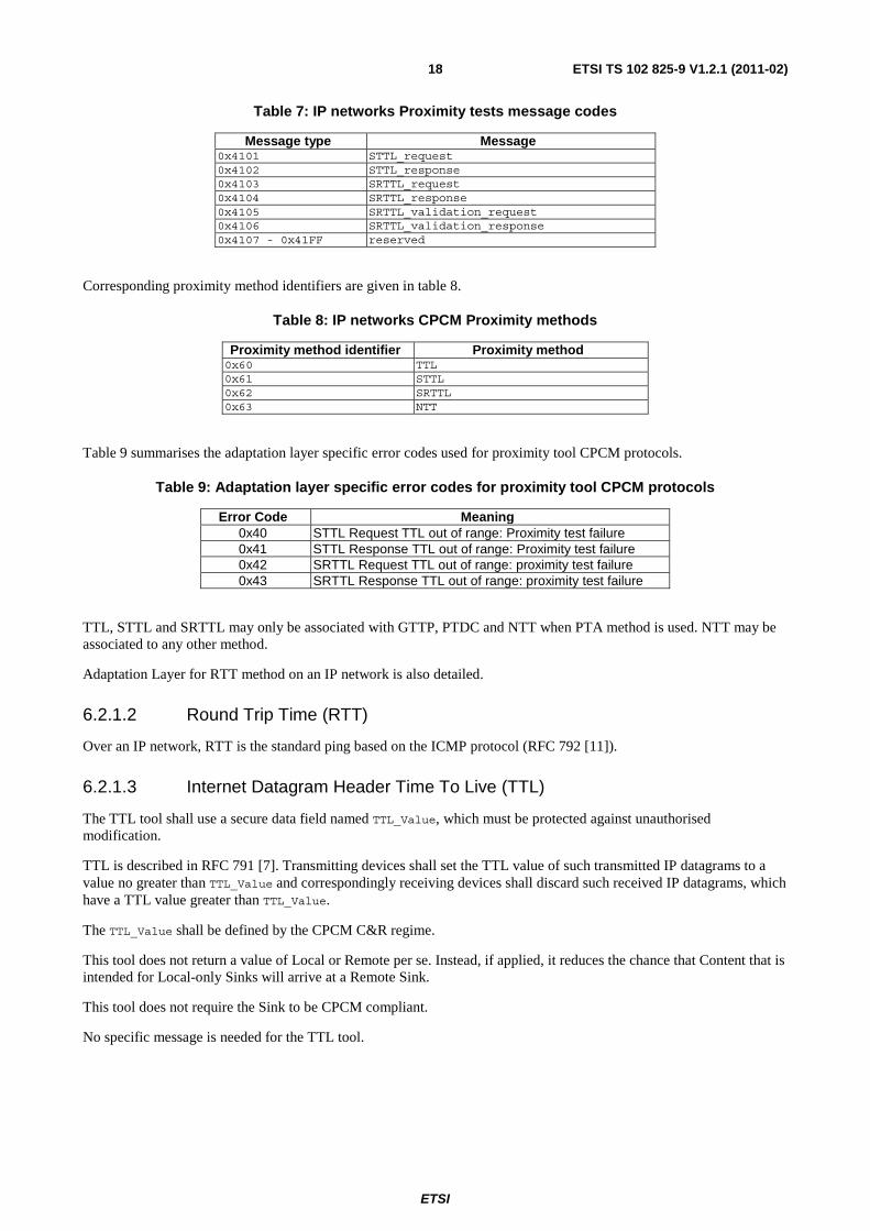
6.2.1.4 Secured Internet Datagram Header Time To Live (STTL)
6.2.1.4.1 General
The secured Internet Datagram Header Time To Live (STTL) tool shall use the same protected data field TTL_value as the unsecured TTL test. The tool may only be run between two CPCM compliant devices. The corresponding protocol is shown in figure 2.
Figure 2: STTL Proximity tool
STTL shall be used as follows:
• CPCM Instance A shall set TTL value TTL_A (greater than TTL_value) to a random value and shall send the message STTL_Request() to the tested device. This message shall be empty and has TTL_A for the TTL_value.
• Upon receipt of message STTL_Request(), the receiving device shall extract the current TTL value TTL_A'. It shall set value TTL_B (greater than TTL_value) to a random value and shall send the message STTL_Response(). This message carries TTL_B and TTL_A' and is encrypted and authenticated with the SAC key. It has TTL_B as the TTL value.
• Upon receipt of message STTL_Response(), the sending device shall extract the current TTL value TTL_B' and recover TTL_B and TTL_A'.
The STTL Test succeeds if and only if:
• TTL_A-TTL_value ≤ TTL_A' ≤ TTL_A.
• TTL_B-TTL_value ≤ TTL_B' ≤ TTL_B.
6.2.1.4.2 STTL Request
void CPCM_sttl_request ( );
Table 10 specifies the CPCM Protocol message for CPCM STTL Request.
Table 10: CPCM STTL Request
Syntax Bits Identifier CPCM_sttl_request_message(){ CPCM_protocol_message_type = 0x4101 16 bslbf control_field = 0x00 8 bslbf message_payload_length 16 uimsbf }
Semantics for CPCM_srttl_request_message:
message_type: According to table 7 this shall be set to 0x4101.
control_field: This message shall be neither signed nor encrypted, hence this shall be set to 0x00.
ETSI
ETSI TS 102 825-9 V1.2.1 (2011-02)20
message_payload_length: The number of message_payload_bytes of the message, hence this shall be set to 0.
There are no specific protocol error codes for that protocol call.
6.2.1.4.3 STTL Response
void CPCM_srttl_response ( ttl ttl_A, ttl ttl_B );
Table 11 specifies the CPCM Protocol message for CPCM STTL Response.
Table 11: CPCM STTL Response
Syntax Bits Identifier CPCM_sttl_response_message(){ CPCM_protocol_message_type = 0x4102 16 bslbf control_field = 0x0A 8 bslbf message_payload_length 16 uimsbf ttl_a 8 bslbf ttl_b 8 bsblf SAC_secret_signature 160 bsblf }
Semantics for CPCM_sttl_response_message:
message_type: According to table 7 this shall be set to 0x4102.
control_field: This message shall be signed and encrypted using the SAC key, hence this shall be set to 0x0A.
message_payload_length: The number of message_payload_bytes of the message, hence this shall be set to 36.
ttl_A: The ttl_value upon receipt of STTL_request message.
ttl_B: The ttl_value of message STTL_response upon sending.
SAC_secret_signature: The signature of the message using SAC session key (see TS 102 825-5 [10]).
The possible CPCM protocol error codes specific to this protocol call are listed in table 12.
Table 12: STTL Response specific error codes
Error Code Meaning 0x40 STTL Request TTL out of range: Proximity test failure 0x41 STTL Response TTL out of range: Proximity test failure
6.2.1.5 Combination of Secured RTT and Secured TTL (SRTTL)
6.2.1.5.1 General
STTL involves the use of two messages. SRTT involves the use of four messages. Using both would thus imply the exchange of up to 6 messages. SRTTL reduces the number of exchanged messages to four. The resulting protocol is shown in figure 3.
ETSI
ETSI TS 102 825-9 V1.2.1 (2011-02)21
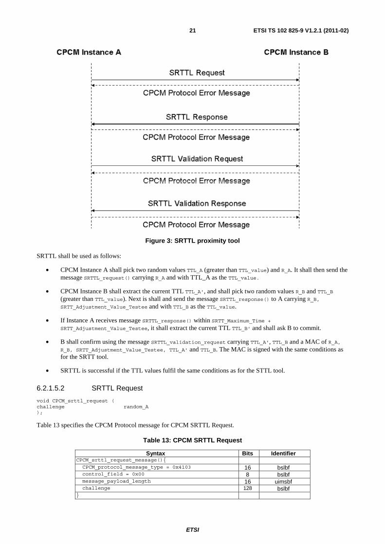
Figure 3: SRTTL proximity tool
SRTTL shall be used as follows:
• CPCM Instance A shall pick two random values TTL_A (greater than TTL_value) and R_A. It shall then send the message SRTTL_request() carrying R_A and with TTL_A as the TTL_value.
• CPCM Instance B shall extract the current TTL TTL_A', and shall pick two random values R_B and TTL_B (greater than TTL_value). Next is shall and send the message SRTTL_response() to A carrying R_B, SRTT_Adjustment_Value_Testee and with TTL_B as the TTL_value.
• If Instance A receives message SRTTL_response() within SRTT_Maximum_Time + SRTT_Adjustment_Value_Testee, it shall extract the current TTL TTL_B' and shall ask B to commit.
• B shall confirm using the message SRTTL_validation_request carrying TTL_A', TTL_B and a MAC of R_A, R_B, SRTT_Adjustment_Value_Testee, TTL_A' and TTL_B. The MAC is signed with the same conditions as for the SRTT tool.
• SRTTL is successful if the TTL values fulfil the same conditions as for the STTL tool.
6.2.1.5.2 SRTTL Request
void CPCM_srttl_request ( challenge random_A );
Table 13 specifies the CPCM Protocol message for CPCM SRTTL Request.
Table 13: CPCM SRTTL Request
Syntax Bits Identifier CPCM_srttl_request_message(){ CPCM_protocol_message_type = 0x4103 16 bslbf control_field = 0x00 8 bslbf message_payload_length 16 uimsbf challenge 128 bslbf }
ETSI
ETSI TS 102 825-9 V1.2.1 (2011-02)22
Semantics for CPCM_srttl_request_message:
message_type: According to table 7 this shall be set to 0x4103.
control_field: This message shall be neither signed nor encrypted, hence this shall be set to 0x00.
message_payload_length: The number of message_payload_bytes of the message, hence this shall be set to 16.
challenge: A random value generated by the calling CPCM Instance to later validate the RTT.
There are no specific protocol error codes for that protocol call.
6.2.1.5.3 SRTTL Response
void CPCM_srttl_response ( challenge random_B, SRTT_adjustment_value value );
Table 14 specifies the CPCM Protocol message for CPCM SRTTL Response.
Table 14: CPCM SRTTL Response
Syntax Bits Identifier CPCM_srttl_response_message(){ CPCM_protocol_message_type = 0x4104 16 bslbf control_field = 0x00 8 bslbf message_payload_length 16 uimsbf challenge 128 bslbf SRTT_adjustment_value 24 bsblf }
Semantics for CPCM_srttl_response_message:
message_type: According to table 7 this shall be set to 0x4104.
control_field: This message shall be neither signed nor encrypted, hence this shall be set to 0x00.
message_payload_length: The number of message_payload_bytes of the message, hence this shall be set to 19.
challenge: A random value generated by the sending CPCM Instance to later validate the RTT.
SRTT_adjustment_value: An adaptation value used to cope with the different network technologies (see clause 6.2.1.4.1).
The possible CPCM protocol error codes specific to this protocol call are listed in table 15.
Table 15: SRTTL Response specific error codes
Error Code Meaning 0x30 RTT too high: Proximity Test aborted
6.2.1.5.4 SRTTL Validation Request
void CPCM_srttl_validation_request ( void ) ;
ETSI
ETSI TS 102 825-9 V1.2.1 (2011-02)23
Table 16 specifies the CPCM Protocol message for CPCM SRTTL Request.
Table 16: CPCM SRTTL Validation Request
Syntax Bits Identifier CPCM_srtt_validation_request_message(){ CPCM_protocol_message_type = 0x4105 16 bslbf control_field = 0x00 8 bslbf message_payload_length 16 uimsbf }
Semantics for CPCM_srttl_validation_request_message:
message_type: According to table 7 this shall be set to 0x4105.
control_field: This message shall be neither signed nor encrypted, hence this shall be set to 0x00.
message_payload_length: The number of message_payload_bytes of the message, hence this shall be set to 0.
There are no specific protocol error codes for that protocol call.
6.2.1.5.5 SRTTL Validation Response
void CPCM_srttl_validation_response ( challenge random_A, challenge random_B SRTT_adjustment_value value ttl ttl_A ttl ttl_B );
Table 17 specifies the CPCM Protocol message for CPCM SRTTL Validation Response.
Table 17: CPCM SRTTL Validation Response
Syntax Bits Identifier CPCM_srttl_response_message(){ CPCM_protocol_message_type = 0x4106 16 bslbf control_field = 0x08 or 0x04 8 bslbf message_payload_length 16 uimsbf random_A 128 bslbf random_B 128 bsblf SRTT_adjustment_value 24 bsblf ttl_A 8 bsblf ttl_B 8 bsblf SAC_secret_signature || AD_secret_signature 160 bsblf }
Semantics for CPCM_srtt_response_message:
message_type: According to table 7 this shall be set to 0x4106.
control_field: This message shall be either signed by SAC session key or the AD Secret, hence it shall be set to either 0x08 or 0x04 respectively.
message_payload_length: The number of message_payload_bytes of the message, hence it shall be set to 57.
random_A: The same random value as sent the SRTTL Request.
random_B: The same random value as sent the SRTTL Response.
ttl_A: The ttl_value upon receipt of SRTTL_request message.
ttl_B: The ttl_value of message SRTTL_response upon sending.
ETSI
ETSI TS 102 825-9 V1.2.1 (2011-02)24
SRTT_adjustment_value: An adaptation value used to cope with the different network technologies (see clause 6.2.1.4.1
SAC_secret_signature: This is the message signature as specified in TS 102 825-5 [10], present only if the control_field is set to 0x08.
ADS_secret_signature: This is the message signature as specified in TS 102 825-5 [10], present only if the control_field is set to 0x04.
The possible CPCM protocol error codes specific to this protocol call are listed in table 18.
Table 18: SRTTL Validation Response specific error codes
Error Code Meaning 0x31 request challenge mismatch: proximity test failure 0x32 response challenge mismatch: proximity test failure 0x42 SRTTL Request TTL out of range: proximity test failure 0x43 SRTTL Response TTL out of range: proximity test failure
6.2.1.6 Network Topology Testing (NTT)
The NTT test shall detect network components by sending specific, well-crafted packets that are processed differently by different components and to thereby derive the network topology.
The NTT tool shall use several secure data fields comprising the "well crafted packages" that will be defined by the CPCM C&R regime, updated from time to time and downloaded for use by CPCM Instances. The "well crafted packages" will be protected against unauthorised modification.
NTT tools comprise the following:
• The Source device sends packets with a valid layer-2 MAC header but invalid layer-3 Network header. These packets will be retransmitted by switches but not by routers. If the packets are received, the receiving device is necessarily Local. However, some Local devices may not receive those packets.
• The Source device uses standard protocols such as UDP datagrams, TCP handshake, IPX/SPX, NetBEUI, and so forth. Local devices always receive those packets. However, some Remote devices may receive those packets as well. A device that does not receive them will necessarily be Remote.
• The Source device sends test packets with an invalid checksum in the 16-bit header of an IP packet. If the packets are received, the receiving device is necessarily Local. However, some Local devices may not receive those packets.
NOTE: NTT can be used without expecting any response from the Sink Device and, as such, no specific message is defined for that tool.
7 CPCM System adaptations for application-specific physical interfaces
Adaptations of the CPCM System are foreseen for physical interfaces that are not envisaged to operate as a generic home network interface within an ecosystem, but rather for those that perform some more specific function that benefits from the application of CPCM to provide content protection functionality over that interface.
CPCM Phase 1 includes adaptation layers for the following CPCM application-specific physical interfaces:
• DVB Common Interface (DVB-CI), as specified in clause 7.1.
• Smart Card Interface ISO/IEC 7816-4 [6], as specified in clause 7.2.
ETSI
ETSI TS 102 825-9 V1.2.1 (2011-02)25
7.1 CPCM System Adaptation for DVB Common Interface
7.1.1 General
This clause specifies how CPCM is adapted to work over the DVB Common Interface (DVB-CI) (see EN 50221 [4]). This is achieved by the definition of a particular copy protection resource, as defined in the DVB Extensions to the Common Interface Specification (see TS 101 699 [5]) that corresponds to a CPCM Instance. The CPCM copy protection resource shall be implemented in both the CI module and the host.
When a CI module that implements a CPCM Instance is inserted into a host that supports CPCM over CI, then any CPCM feature can be utilised between the module and the host, depending on the respective CPCM Instance implementations.
Since the CI module would normally implement a CPCM Acquisition Point, in order to act as a Source of CPCM Content for the host, all CPCM elements not required in order to perform the Acquisition of CPCM Content are optional for such CI modules.
As is generally the case for CPCM Devices, the CI host, being a Sink for CPCM Content that is Acquired by the CI module, will need to implement all CPCM elements that it needs in order to fulfil its intended functionality with respect to CPCM.
CPCM Instances identify and communicate with each other over the DVB-CI by way of the CI Command Interface. The method of identification of CPCM copy protection resources and the mapping of the CPCM Protocol messages to the CI Command Interface are specified in clause 7.1.2.
This adaptation of CPCM to DVB-CI enables standardised methods to be employed for the mutual authentication between CI modules and their host devices, and to secure the return transport stream from a CI module to the host device. For this purpose only a minimal subset of the CPCM System needs to be implemented in both the CI module and the host. This particular subset is described in clause 7.1.3.
7.1.2 Additional Requirements for CPCM support
In order to support CPCM, the interrupt mode implementation, defined as optional in the DVB-CI specifications ([5]), becomes mandatory. The DVB CI module shall announce the interrupt mode support in the Card Information Structure (CIS).
A host shall switch to interrupt mode as soon as the DVB CI module triggers interrupt mode.
7.1.3 CPCM System Adaptation to DVB-CI
The CPCM Instances in both the Module and the Host shall be implemented as Copy Protection resources as defined in TS 101 699 [5].
Copy Protection resources are identified by the CopyProtectionID field, whereby the IEEE company_id (see TS 102 825-5 [10]) is used to identify the copy protection system. Copy Protection resources for CPCM shall set their CopyProtectionID value to the IEEE company_id that has been allocated to DVB, namely 0x00015A.
According to TS 101 699 [5], a Copy Protection resource implements four CI Command Interface messages, namely CP_query, CP_reply, CP_command and CP_response.
The CP_query message shall be used to mutually verify the presence of a CPCM Instance by the module and the host. The syntax of the CP_query message for CPCM is shown in table 19.
Table 19: CP_query CI Command Interface message for CPCM
Syntax Bits Identifier cp_query(){ CopyProtectionQueryTag = 0x9F8000 24 uimsbf length_field = 0x03 8 uimsbf CopyProtectionID = 0x00015A 24 uimsbf }
ETSI
ETSI TS 102 825-9 V1.2.1 (2011-02)26
When the module or host that implements a CPCM Instance receives a CP_query message it shall send a corresponding CP_reply message as shown in table 20.
Table 20: CP_reply CI Command Interface message for CPCM
Syntax Bits Identifier cp_reply(){ CPReplyTag = 0x9F8001 24 uimsbf length_field = 0x04 8 uimsbf CopyProtectionID = 0x00015A 24 uimsbf status 8 uimsbf }
Semantics for CP_reply:
status: If the CopyProtectionID field of the cp_query message was set to 0x00015A, then status shall be set to 0x02 ("Copy Protection Active"), otherwise Status shall be set to 0xFF ("ID mismatch").
CPCM Instances implemented in a module or the host shall use the CPCM Protocol messages as specified in the relevant section of the CPCM System Specification to communicate with each other, whereby the CP_command CI Command Interface message is used to send a CPCM Protocol message request as shown in table 21, and the CP_response CI Command Interface message is used to send a CPCM Protocol Error message (if an error occurs) as shown in table 22.
Table 21: CP_command CI Command Interface message for CPCM
Syntax Bits Identifier cp_command(){ CPCommandTag = 0x9F8002 24 uimsbf length_field() CopyProtectionID = 0x00015A 24 uimsbf for (i=0; i<N; i++){ CPCommandByte 8 uimsbf } }
Semantics for CP_command:
length_field: This can vary according to the length of the CPCM Protocol Request message being sent. See EN 50221 [4] for its syntax.
CPCommandByte: CPCM Protocol Request message byte.
Table 22: CP_response CI Command Interface message for CPCM
Syntax Bits Identifier cp_response(){ CPResponseTag = 0x9F8003 24 uimsbf length_field = 0x08 8 uimsbf CopyProtectionID = 0x00015A 24 uimsbf for (i=0; i<N; i++){ CPResponseByte 8 uimsbf } }
Semantics for CP_response:
length_field: The length_field for cp_response shall be set to 0x08, as the length of CPCM Protocol Error messages within cp_response messages is always 5 bytes.
CPResponseByte: CPCM Protocol Error message byte.
ETSI
ETSI TS 102 825-9 V1.2.1 (2011-02)27
7.1.4 Minimal CPCM Implementation for Protected Input Content Acquisition over DVB-CI
7.1.4.1 General
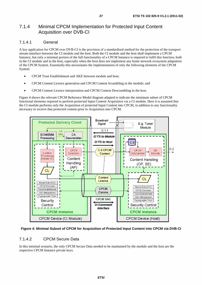
A key application for CPCM over DVB-CI is the provision of a standardised method for the protection of the transport stream interface between the CI module and the host. Both the CI module and the host shall implement a CPCM Instance, but only a minimal portion of the full functionality of a CPCM Instance is required to fulfil this function, both in the CI module and in the host, especially when the host does not implement any home network ecosystem adaptation of the CPCM System. Essentially this necessitates the implementation of only the following elements of the CPCM System:
• CPCM Trust Establishment and AKE between module and host;
• CPCM Content Licence generation and CPCM Content Scrambling in the module; and
• CPCM Content Licence interpretation and CPCM Content Descrambling in the host.
Figure 4 shows the relevant CPCM Reference Model diagram adapted to indicate the minimum subset of CPCM functional elements required to perform protected Input Content Acquisition via a CI module. Here it is assumed that the CI module performs only the Acquisition of protected Input Content into CPCM, in addition to any functionality necessary to receive that protected content prior to Acquisition into CPCM.
Figure 4: Minimal Subset of CPCM for Acquisition of Protected Input Content into CPCM via DVB-CI
7.1.4.2 CPCM Secure Data
In this minimal scenario, the only CPCM Secure Data needed to be maintained by the module and the host are the respective CPCM Instance private keys.
ETSI
ETSI TS 102 825-9 V1.2.1 (2011-02)28
7.1.4.3 CPCM LSA
The CPCM Security Toolbox specification defines the CPCM LSA (Local Scrambling Algorithm) as having two possible chaining modes and two possible IV preparation modes, thus resulting in four possible combinations of these scrambling options.
Since it is always the CPCM Content Source that decides which of these four combinations to apply for any CPCM Content Item (or protected CPCM Content stream), the CPCM Instance in the CI module could also always apply the same combination to all CPCM Content that it has Acquired. Hence the CI module does not necessarily need to implement the other CPCM Scrambler combinations, if this would enable a quicker implementation of such CPCM-compliant CI modules.
In order to guarantee interoperability with all potential Sources of CPCM Content, the CI host device needs to implement all four combinations of the CPCM Descrambler options.
7.1.4.4 CPCM Protocols
From the set of CPCM Protocols defined in TS 102 825-4 [9], only the following subset needs to be implemented:
• CPCM AKE (CPCM_AKE_init, CPCM_AKE_commit, CPCM_AKE_renew, CPCM_AKE_commit_renew, CPCM_AKE_confirm, CPCM_AKE_terminate); and
• CPCM Content Licence Exchange (CPCM_put_CL from module to host).
The CPCM System does not specify under what circumstances the CPCM Content Scrambling Key is updated. This is left to the discretion of the implementation and/or C&R Regime.
7.1.4.5 CPCM Proximity Control
CPCM Proximity Control is required to be implemented on DVB-CI.
The CI module and the host shall apply the Secure Round Trip Time (SRTT) Proximity Control Protocol, as defined above, to verify that they are actually physically co-located.
Before performing a RTT or a SRTT proximity test, the CI module shall trigger the interrupt mode.
SRTT shall be run after CPCM Trust has been established and CPCM AKE has been completed.
The key used to sign the SRTT_confirm() message shall be the session key computed during CPCM AKE.
Values for network_type_tester, SRTT_maximum_time, SRTT_persistence and SRTT_adjustement_value_testee will be set by the C&R regime.
7.2 CPCM System Specification for ISO7816 Smart Card Interface
7.2.1 General
This clause specifies how CPCM is adapted to work over the ISO/IEC 7816-4 [6] Smart Card Interface. In the following clauses an ISO/IEC 7816-4 [6] smart card with an embedded CPCM Instance is referred to as a CPCM smart card. The physical interface can be a contact interface (ISO/IEC 7816-1 [15], 2 [16] and 3 [17]) or a contactless interface (ISO-IEC 14443-1 [18], 2 [19], 3 [20] and 4 [21]).
This clause is mandatory when the smart card embeds a CPCM Instance but has no CAS, DRM or CPS system. It is optional in all other cases.
ETSI
ETSI TS 102 825-9 V1.2.1 (2011-02)29
7.2.2 ISO/IEC 7816 background
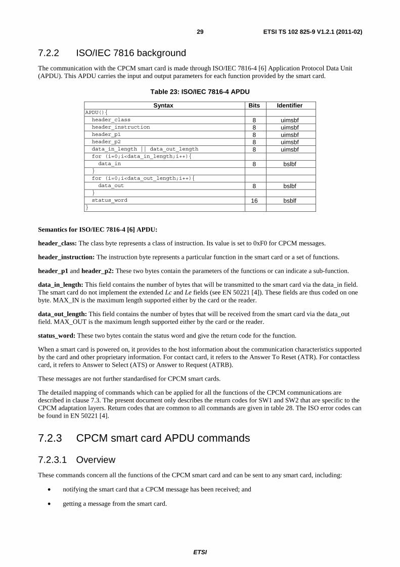
The communication with the CPCM smart card is made through ISO/IEC 7816-4 [6] Application Protocol Data Unit (APDU). This APDU carries the input and output parameters for each function provided by the smart card.
Table 23: ISO/IEC 7816-4 APDU
Syntax Bits Identifier APDU(){ header_class 8 uimsbf header_instruction 8 uimsbf header_p1 8 uimsbf header_p2 8 uimsbf data_in_length || data_out_length 8 uimsbf for (i=0;i<data_in_length;i++){ data_in 8 bslbf } for (i=0;i<data_out_length;i++){ data_out 8 bslbf } status_word 16 bsblf }
Semantics for ISO/IEC 7816-4 [6] APDU:
header_class: The class byte represents a class of instruction. Its value is set to 0xF0 for CPCM messages.
header_instruction: The instruction byte represents a particular function in the smart card or a set of functions.
header_p1 and header_p2: These two bytes contain the parameters of the functions or can indicate a sub-function.
data_in_length: This field contains the number of bytes that will be transmitted to the smart card via the data_in field. The smart card do not implement the extended Lc and Le fields (see EN 50221 [4]). These fields are thus coded on one byte. MAX_IN is the maximum length supported either by the card or the reader.
data_out_length: This field contains the number of bytes that will be received from the smart card via the data_out field. MAX_OUT is the maximum length supported either by the card or the reader.
status_word: These two bytes contain the status word and give the return code for the function.
When a smart card is powered on, it provides to the host information about the communication characteristics supported by the card and other proprietary information. For contact card, it refers to the Answer To Reset (ATR). For contactless card, it refers to Answer to Select (ATS) or Answer to Request (ATRB).
These messages are not further standardised for CPCM smart cards.
The detailed mapping of commands which can be applied for all the functions of the CPCM communications are described in clause 7.3. The present document only describes the return codes for SW1 and SW2 that are specific to the CPCM adaptation layers. Return codes that are common to all commands are given in table 28. The ISO error codes can be found in EN 50221 [4].
7.2.3 CPCM smart card APDU commands
7.2.3.1 Overview
These commands concern all the functions of the CPCM smart card and can be sent to any smart card, including:
• notifying the smart card that a CPCM message has been received; and
• getting a message from the smart card.
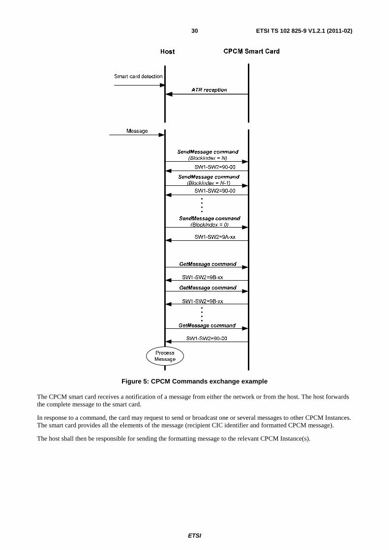
ETSI
ETSI TS 102 825-9 V1.2.1 (2011-02)30
Host CPCM Smart Card
Smart card detection
Message
SendMessage command
(BlockIndex = N)
SW1-SW2=90-00
SW1-SW2=90-00
GetMessage command
ATR reception
SW1-SW2=9A-xx
SW1-SW2=9B-xx
SW1-SW2=9B-xx
GetMessage command
GetMessage command
Process
Message
SendMessage command
(BlockIndex = N-1)
SendMessage command
(BlockIndex = 0)
SW1-SW2=90-00
Figure 5: CPCM Commands exchange example
The CPCM smart card receives a notification of a message from either the network or from the host. The host forwards the complete message to the smart card.
In response to a command, the card may request to send or broadcast one or several messages to other CPCM Instances. The smart card provides all the elements of the message (recipient CIC identifier and formatted CPCM message).
The host shall then be responsible for sending the formatting message to the relevant CPCM Instance(s).
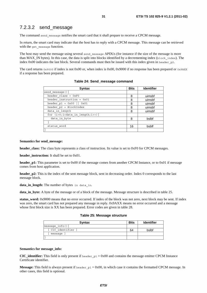
ETSI
ETSI TS 102 825-9 V1.2.1 (2011-02)31
7.2.3.2 send_message
The command send_message notifies the smart card that it shall prepare to receive a CPCM message.
In return, the smart card may indicate that the host has to reply with a CPCM message. This message can be retrieved with the get_message function.
The host may send the message using several send_message APDUs (for instance if the size of the message is more than MAX_IN bytes). In this case, the data is split into blocks identified by a decrementing index (block_index). The index 0x00 indicates the last block. Several commands must then be issued with this index given in header_p2.
The card returns 0x9000 if index is not 0x00 or, when index is 0x00, 0x9000 if no response has been prepared or 0x9AXX if a response has been prepared.
Table 24: Send_message command
Syntax Bits Identifier send_message(){ header_class = 0xF0 8 uimsbf header_instruction = 0x01 8 uimsbf header_p1 = 0x00 || 0x01 8 uimsbf header_p2 = BlockIndex 8 uimsbf data_in_length 8 uimsbf for (i=0;i<data_in_length;i++){ data_in_byte 8 bslbf } status_word 16 bsblf }
Semantics for send_message:
header_class: The class byte represents a class of instruction. Its value is set to 0xF0 for CPCM messages.
header_instruction: It shall be set to 0x01.
header_p1: This parameter is set to 0x00 if the message comes from another CPCM Instance, or to 0x01 if message comes from host application.
header_p2: This is the index of the sent message block, sent in decreasing order. Index 0 corresponds to the last message block.
data_in_length: The number of bytes in data_in.
data_in_byte: A byte of the message or of a block of the message. Message structure is described in table 25.
status_word: 0x9000 means that no error occurred. If index of the block was not zero, next block may be sent. If index was zero, the smart card has not prepared any message in reply. 0x9AXX means no error occurred and a message whose first block size is XX has been prepared. Error codes are given in table 28.
Table 25: Message structure
Syntax Bits Identifier message_info(){ [ CIC_identifier ] 64 bslbf [ message ] }
Semantics for message_info:
CIC_identifier: This field is only present if header_p1 = 0x00 and contains the message emitter CPCM Instance Certificate identifier.
Message: This field is always present if header_p1 = 0x00, in which case it contains the formatted CPCM message. In other cases, this field is optional.
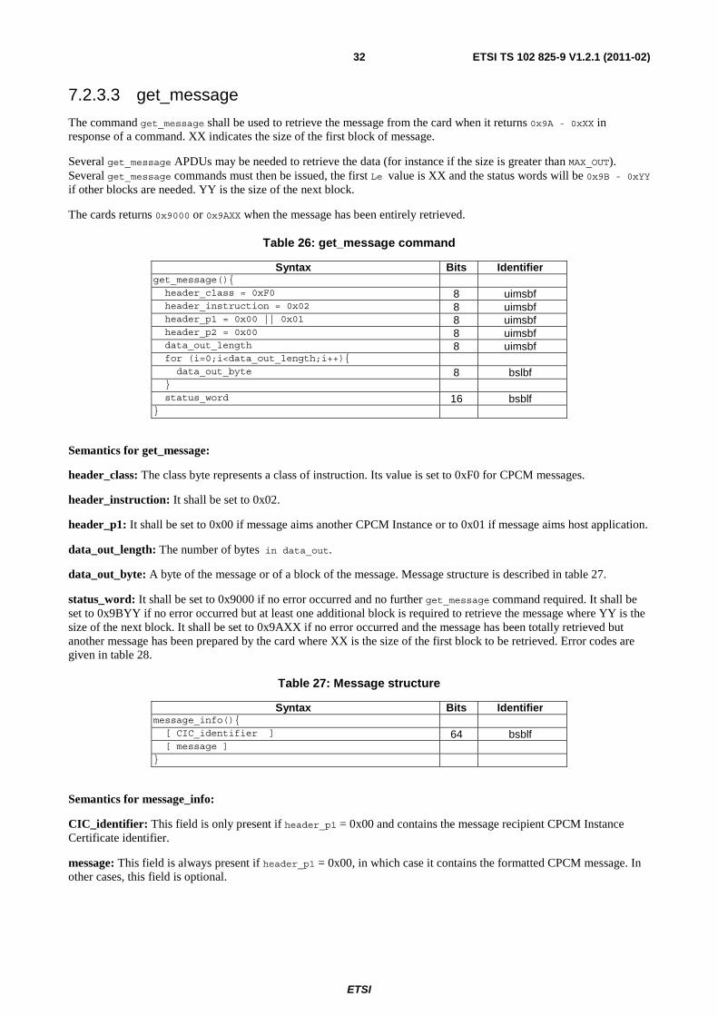
ETSI
ETSI TS 102 825-9 V1.2.1 (2011-02)32
7.2.3.3 get_message
The command get_message shall be used to retrieve the message from the card when it returns 0x9A - 0xXX in response of a command. XX indicates the size of the first block of message.
Several get_message APDUs may be needed to retrieve the data (for instance if the size is greater than MAX_OUT). Several get_message commands must then be issued, the first Le value is XX and the status words will be 0x9B - 0xYY if other blocks are needed. YY is the size of the next block.
The cards returns 0x9000 or 0x9AXX when the message has been entirely retrieved.
Table 26: get_message command
Syntax Bits Identifier get_message(){ header_class = 0xF0 8 uimsbf header_instruction = 0x02 8 uimsbf header_p1 = 0x00 || 0x01 8 uimsbf header_p2 = 0x00 8 uimsbf data_out_length 8 uimsbf for (i=0;i<data_out_length;i++){ data_out_byte 8 bslbf } status_word 16 bsblf }
Semantics for get_message:
header_class: The class byte represents a class of instruction. Its value is set to 0xF0 for CPCM messages.
header_instruction: It shall be set to 0x02.
header_p1: It shall be set to 0x00 if message aims another CPCM Instance or to 0x01 if message aims host application.
data_out_length: The number of bytes in data_out.
data_out_byte: A byte of the message or of a block of the message. Message structure is described in table 27.
status_word: It shall be set to 0x9000 if no error occurred and no further get_message command required. It shall be set to 0x9BYY if no error occurred but at least one additional block is required to retrieve the message where YY is the size of the next block. It shall be set to 0x9AXX if no error occurred and the message has been totally retrieved but another message has been prepared by the card where XX is the size of the first block to be retrieved. Error codes are given in table 28.
Table 27: Message structure
Syntax Bits Identifier message_info(){ [ CIC_identifier ] 64 bsblf [ message ] }
Semantics for message_info:
CIC_identifier: This field is only present if header_p1 = 0x00 and contains the message recipient CPCM Instance Certificate identifier.
message: This field is always present if header_p1 = 0x00, in which case it contains the formatted CPCM message. In other cases, this field is optional.
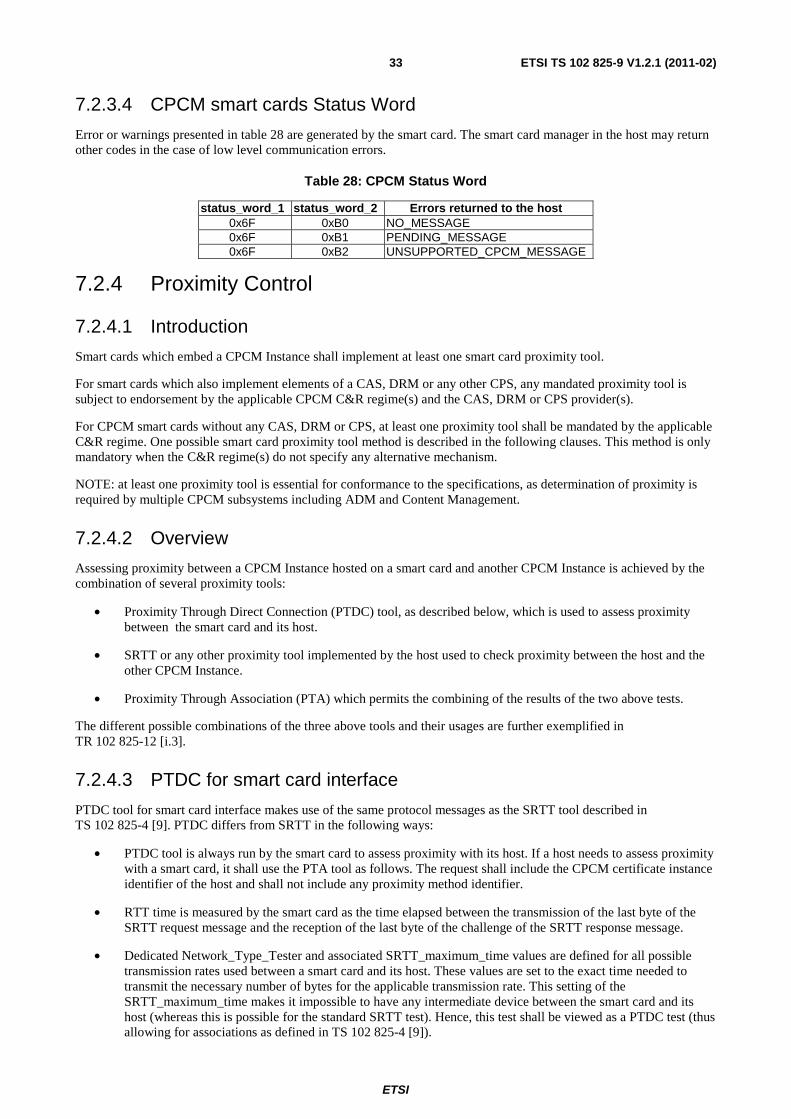
ETSI
ETSI TS 102 825-9 V1.2.1 (2011-02)33
7.2.3.4 CPCM smart cards Status Word
Error or warnings presented in table 28 are generated by the smart card. The smart card manager in the host may return other codes in the case of low level communication errors.
Table 28: CPCM Status Word
status_word_1 status_word_2 Errors returned to the host 0x6F 0xB0 NO_MESSAGE 0x6F 0xB1 PENDING_MESSAGE 0x6F 0xB2 UNSUPPORTED_CPCM_MESSAGE
7.2.4 Proximity Control
7.2.4.1 Introduction
Smart cards which embed a CPCM Instance shall implement at least one smart card proximity tool.
For smart cards which also implement elements of a CAS, DRM or any other CPS, any mandated proximity tool is subject to endorsement by the applicable CPCM C&R regime(s) and the CAS, DRM or CPS provider(s).
For CPCM smart cards without any CAS, DRM or CPS, at least one proximity tool shall be mandated by the applicable C&R regime. One possible smart card proximity tool method is described in the following clauses. This method is only mandatory when the C&R regime(s) do not specify any alternative mechanism.
NOTE: at least one proximity tool is essential for conformance to the specifications, as determination of proximity is required by multiple CPCM subsystems including ADM and Content Management.
7.2.4.2 Overview
Assessing proximity between a CPCM Instance hosted on a smart card and another CPCM Instance is achieved by the combination of several proximity tools:
• Proximity Through Direct Connection (PTDC) tool, as described below, which is used to assess proximity between the smart card and its host.
• SRTT or any other proximity tool implemented by the host used to check proximity between the host and the other CPCM Instance.
• Proximity Through Association (PTA) which permits the combining of the results of the two above tests.
The different possible combinations of the three above tools and their usages are further exemplified in TR 102 825-12 [i.3].
7.2.4.3 PTDC for smart card interface
PTDC tool for smart card interface makes use of the same protocol messages as the SRTT tool described in TS 102 825-4 [9]. PTDC differs from SRTT in the following ways:
• PTDC tool is always run by the smart card to assess proximity with its host. If a host needs to assess proximity with a smart card, it shall use the PTA tool as follows. The request shall include the CPCM certificate instance identifier of the host and shall not include any proximity method identifier.
• RTT time is measured by the smart card as the time elapsed between the transmission of the last byte of the SRTT request message and the reception of the last byte of the challenge of the SRTT response message.
• Dedicated Network_Type_Tester and associated SRTT_maximum_time values are defined for all possible transmission rates used between a smart card and its host. These values are set to the exact time needed to transmit the necessary number of bytes for the applicable transmission rate. This setting of the SRTT_maximum_time makes it impossible to have any intermediate device between the smart card and its host (whereas this is possible for the standard SRTT test). Hence, this test shall be viewed as a PTDC test (thus allowing for associations as defined in TS 102 825-4 [9]).
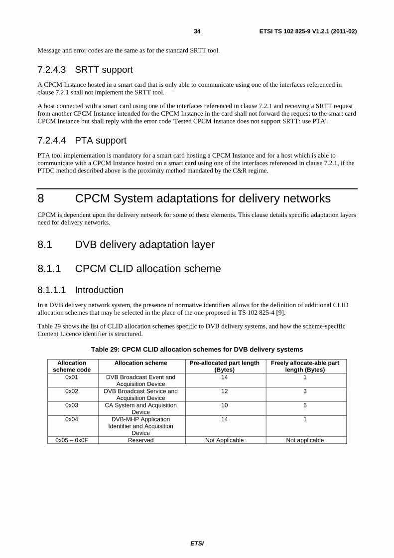
ETSI
ETSI TS 102 825-9 V1.2.1 (2011-02)34
Message and error codes are the same as for the standard SRTT tool.
7.2.4.3 SRTT support
A CPCM Instance hosted in a smart card that is only able to communicate using one of the interfaces referenced in clause 7.2.1 shall not implement the SRTT tool.
A host connected with a smart card using one of the interfaces referenced in clause 7.2.1 and receiving a SRTT request from another CPCM Instance intended for the CPCM Instance in the card shall not forward the request to the smart card CPCM Instance but shall reply with the error code 'Tested CPCM Instance does not support SRTT: use PTA'.
7.2.4.4 PTA support
PTA tool implementation is mandatory for a smart card hosting a CPCM Instance and for a host which is able to communicate with a CPCM Instance hosted on a smart card using one of the interfaces referenced in clause 7.2.1, if the PTDC method described above is the proximity method mandated by the C&R regime.
8 CPCM System adaptations for delivery networks CPCM is dependent upon the delivery network for some of these elements. This clause details specific adaptation layers need for delivery networks.
8.1 DVB delivery adaptation layer
8.1.1 CPCM CLID allocation scheme
8.1.1.1 Introduction
In a DVB delivery network system, the presence of normative identifiers allows for the definition of additional CLID allocation schemes that may be selected in the place of the one proposed in TS 102 825-4 [9].
Table 29 shows the list of CLID allocation schemes specific to DVB delivery systems, and how the scheme-specific Content Licence identifier is structured.
Table 29: CPCM CLID allocation schemes for DVB delivery systems
Allocation scheme code
Allocation scheme Pre-allocated part length (Bytes)
Freely allocate-able part length (Bytes)
0x01 DVB Broadcast Event and Acquisition Device
14 1
0x02 DVB Broadcast Service and Acquisition Device
12 3
0x03 CA System and Acquisition Device
10 5
0x04 DVB-MHP Application Identifier and Acquisition
Device
14 1
0x05 – 0x0F Reserved Not Applicable Not applicable
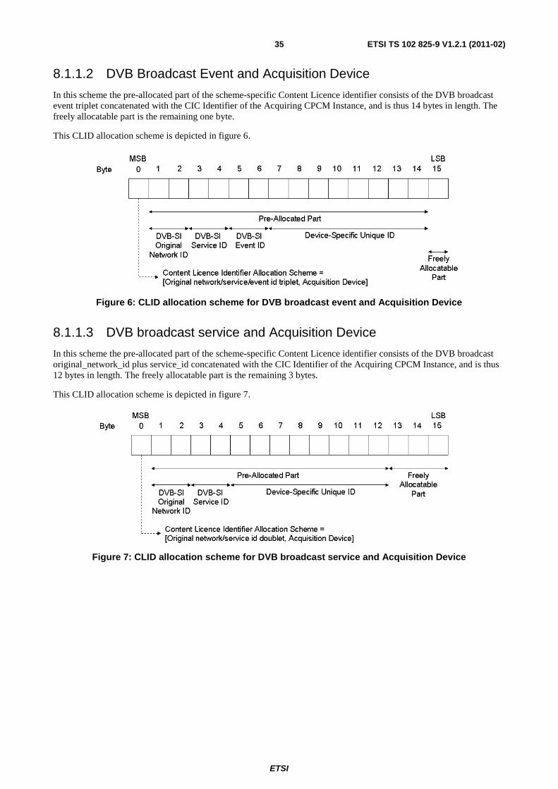
ETSI
ETSI TS 102 825-9 V1.2.1 (2011-02)35
8.1.1.2 DVB Broadcast Event and Acquisition Device
In this scheme the pre-allocated part of the scheme-specific Content Licence identifier consists of the DVB broadcast event triplet concatenated with the CIC Identifier of the Acquiring CPCM Instance, and is thus 14 bytes in length. The freely allocatable part is the remaining one byte.
This CLID allocation scheme is depicted in figure 6.
Figure 6: CLID allocation scheme for DVB broadcast event and Acquisition Device
8.1.1.3 DVB broadcast service and Acquisition Device
In this scheme the pre-allocated part of the scheme-specific Content Licence identifier consists of the DVB broadcast original_network_id plus service_id concatenated with the CIC Identifier of the Acquiring CPCM Instance, and is thus 12 bytes in length. The freely allocatable part is the remaining 3 bytes.
This CLID allocation scheme is depicted in figure 7.
Figure 7: CLID allocation scheme for DVB broadcast service and Acquisition Device
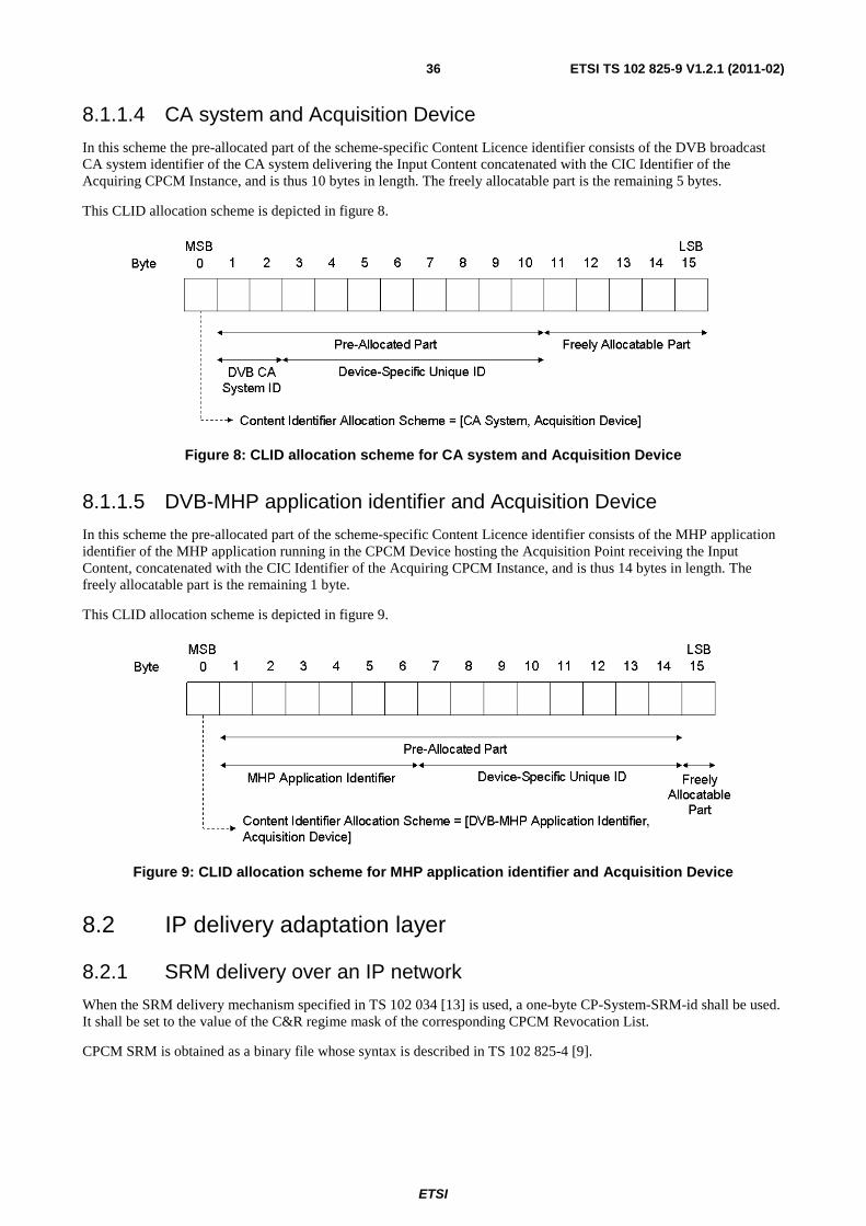
ETSI
ETSI TS 102 825-9 V1.2.1 (2011-02)36
8.1.1.4 CA system and Acquisition Device
In this scheme the pre-allocated part of the scheme-specific Content Licence identifier consists of the DVB broadcast CA system identifier of the CA system delivering the Input Content concatenated with the CIC Identifier of the Acquiring CPCM Instance, and is thus 10 bytes in length. The freely allocatable part is the remaining 5 bytes.
This CLID allocation scheme is depicted in figure 8.
Figure 8: CLID allocation scheme for CA system and Acquisition Device
8.1.1.5 DVB-MHP application identifier and Acquisition Device
In this scheme the pre-allocated part of the scheme-specific Content Licence identifier consists of the MHP application identifier of the MHP application running in the CPCM Device hosting the Acquisition Point receiving the Input Content, concatenated with the CIC Identifier of the Acquiring CPCM Instance, and is thus 14 bytes in length. The freely allocatable part is the remaining 1 byte.
This CLID allocation scheme is depicted in figure 9.
Figure 9: CLID allocation scheme for MHP application identifier and Acquisition Device
8.2 IP delivery adaptation layer
8.2.1 SRM delivery over an IP network
When the SRM delivery mechanism specified in TS 102 034 [13] is used, a one-byte CP-System-SRM-id shall be used. It shall be set to the value of the C&R regime mask of the corresponding CPCM Revocation List.
CPCM SRM is obtained as a binary file whose syntax is described in TS 102 825-4 [9].

ETSI
ETSI TS 102 825-9 V1.2.1 (2011-02)37
Annex A (informative): Bibliography
• IEEE List of Registered OUI.
NOTE: Available at: http://standards.ieee.org/regauth/oui/index.shtml.
ETSI
ETSI TS 102 825-9 V1.2.1 (2011-02)38
List of tables Table 1: Application of TS header scrambling control bits ................................................................................................ 8
Table 2: CPCM delivery signalling descriptor ................................................................................................................... 9
Table 3: DVB-CPCM::GetCapabilities() ..........................................................................................................................12
Table 4: DVB-CPCM::SendMessage() .............................................................................................................................13
Table 5: UPnP Error messages ..........................................................................................................................................13
Table 6: Typical example of a CPCM message using UPnP .............................................................................................17
Table 7: IP networks Proximity tests message codes ........................................................................................................17
Table 8: IP networks CPCM Proximity methods ..............................................................................................................18
Table 9: Adaptation layer specific error codes for proximity tool CPCM protocols .........................................................18
Table 10: CPCM STTL Request .......................................................................................................................................19
Table 11: CPCM STTL Response .....................................................................................................................................20
Table 12: STTL Response specific error codes .................................................................................................................20
Table 13: CPCM SRTTL Request .....................................................................................................................................21
Table 14: CPCM SRTTL Response ..................................................................................................................................22
Table 15: SRTTL Response specific error codes ..............................................................................................................22
Table 16: CPCM SRTTL Validation Request ...................................................................................................................23
Table 17: CPCM SRTTL Validation Response ................................................................................................................23
Table 18: SRTTL Validation Response specific error codes ............................................................................................24
Table 19: CP_query CI Command Interface message for CPCM .....................................................................................25
Table 20: CP_reply CI Command Interface message for CPCM ......................................................................................26
Table 21: CP_command CI Command Interface message for CPCM ..............................................................................26
Table 22: CP_response CI Command Interface message for CPCM ................................................................................26
Table 23: ISO 7816-4 APDU ............................................................................................................................................29
Table 24: Send_message command...................................................................................................................................31
Table 25: Message structure ..............................................................................................................................................31
Table 26: get_message command ......................................................................................................................................32
Table 27: Message structure ..............................................................................................................................................32
Table 28: CPCM Status Word ...........................................................................................................................................33
Table 29: CPCM CLID allocation schemes for DVB delivery systems ............................................................................34
ETSI
ETSI TS 102 825-9 V1.2.1 (2011-02)39
List of figures Figure 1: typical behaviour of the DVB-HN NAL for CPCM ..........................................................................................16
Figure 2: STTL Proximity tool ..........................................................................................................................................19
Figure 3: SRTTL proximity tool .......................................................................................................................................21
Figure 4: Minimal Subset of CPCM for Acquisition of Protected Input Content into CPCM via DVB-CI ......................27
Figure 5: CPCM Commands exchange example ...............................................................................................................30
Figure 6: CLID allocation scheme for DVB broadcast event and Acquisition Device .....................................................35
Figure 7: CLID allocation scheme for DVB broadcast service and Acquisition Device ..................................................35
Figure 8: CLID allocation scheme for CA system and Acquisition Device ......................................................................36
Figure 9: CLID allocation scheme for MHP application identifier and Acquisition Device.............................................36

ETSI
ETSI TS 102 825-9 V1.2.1 (2011-02)40
History
Document history
V1.1.1 July 2008 Publication
V1.2.1 February 2011 Publication