Embed Size (px)
Citation preview
Civil Engineering Land Surveying Landscape Architecture Environmental Services
478 Blair Park Road Williston, VT 05495 802 879 6331 www.tcevt.com
T R U D E L LConsulting Engineers
Eastern Development Corporation40 Plains RoadVtrans Stormwater Design BriefMay 8, 2019
1. Project Description
Eastern Development Corporation (Applicant) proposes the construction of a9,100 SF retail building located at 40 Plains Rd in Pittsford, VT. As existing, the 2.78acre site includes a house, paved drive and concrete slab which will bedemolished and removed. This existing development totals to 9,062 SF (0.21acres) of impervious surface. The proposed project includes a building withroughly a 9,100 SF footprint and a 33-space parking lot, with a total of 34,640 SF(0.80 acres) of impervious surface, or 29% lot coverage (building and parking).The total impervious surface on-site is proposed to increase by 25,578 SF (0.59acres).
As the total impervious coverage on-site is less than 1 acre, there are no staterequirements for stormwater treatment. Per Section 1003.C.2.g of the PittsfordZoning Regulations, stormwater drainage is to be treated on-site where practicaland should not create an adverse impact upon the municipality or neighboringproperties. In accordance with Vtrans standards, proposed peak runoff rates forthe 25-year and 50-year storms should be less than or equal to the peak rates forthe existing conditions where runoff discharges to a state right-of-way. To ensurecompliance with these provisions, the existing and proposed sites have beenhydrologically modeled.
2. Receiving Waters
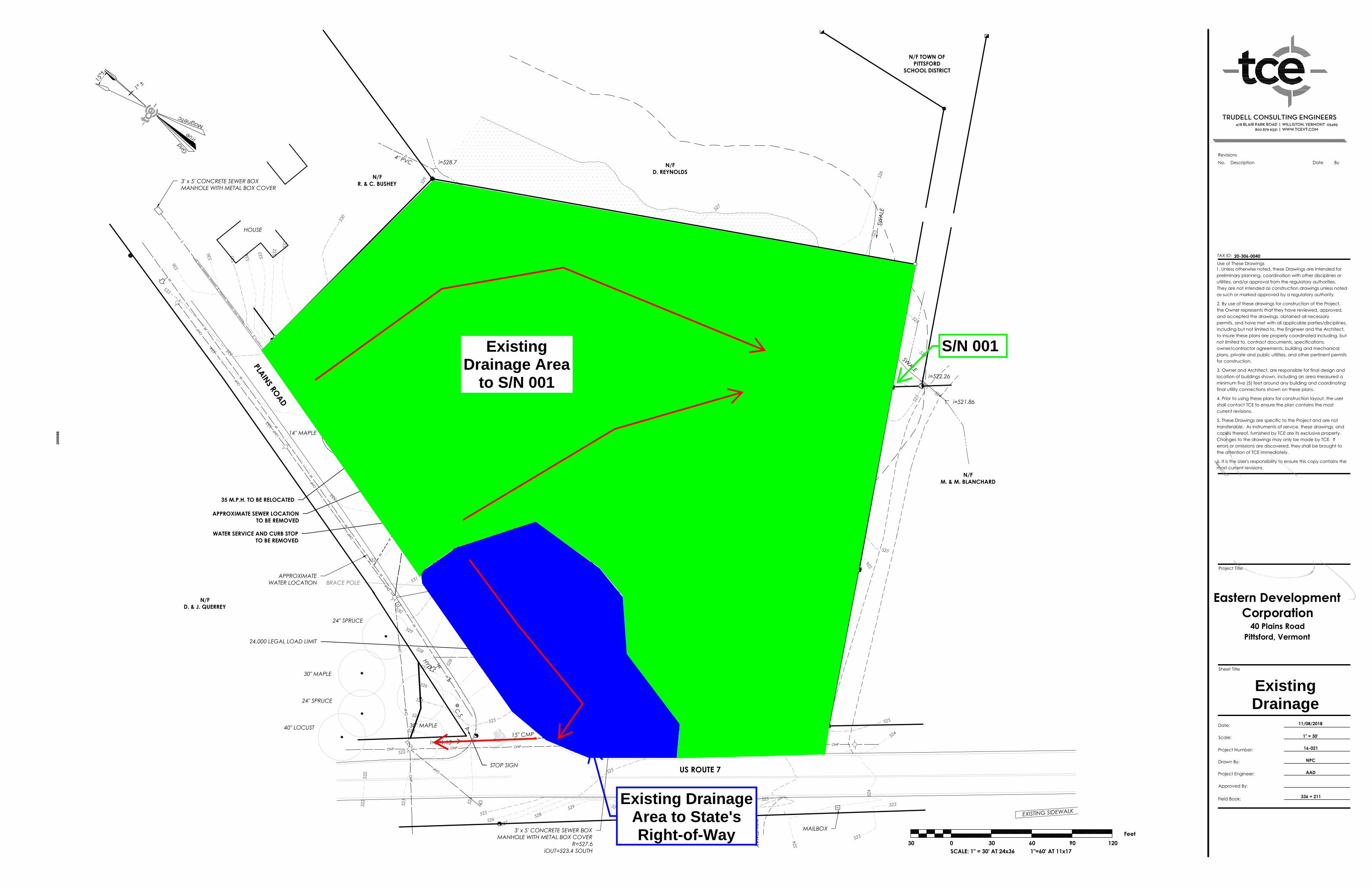
Stormwater runoff from this site currently leaves the property southeast of thedevelopment through a culvert beneath the neighboring driveway. Thisdischarge location will be referred to as S/N 001. Water then flows through aswale and eventually crosses Route 7 before it discharges to Otter Creek,approximately 3,000 feet south of the project parcel.
3. Existing Conditions
The site currently consists of a 2.78 acre parcel with a single family home locatednear Plains Rd. Impervious cover on the site is approximately 9,062 SF and is
Page 2Stormwater Narrative – Eastern Development CorporationMay 8, 2019
limited to the existing house, driveway and a large concrete slab. The remainderof the site is open space, with grass predominating on the south portion of theparcel and a Class II wet meadow on the east side of the parcel. The wetmeadow contains a seasonal drainage swale which flows to a farm pond. Thefarm pond then drains through a culvert to a swale southeast off the property.The site is relatively flat, with an approximately 1% grade in the north-southdirection and an approximately 2% grade in the east-west direction. In additionto the project area, off-site stormwater flows onto the property. This includes theprominent residential development to the north along Plains Rd. The totaldrainage area to discharge location S/N 001 is approximately 42.8 acres.
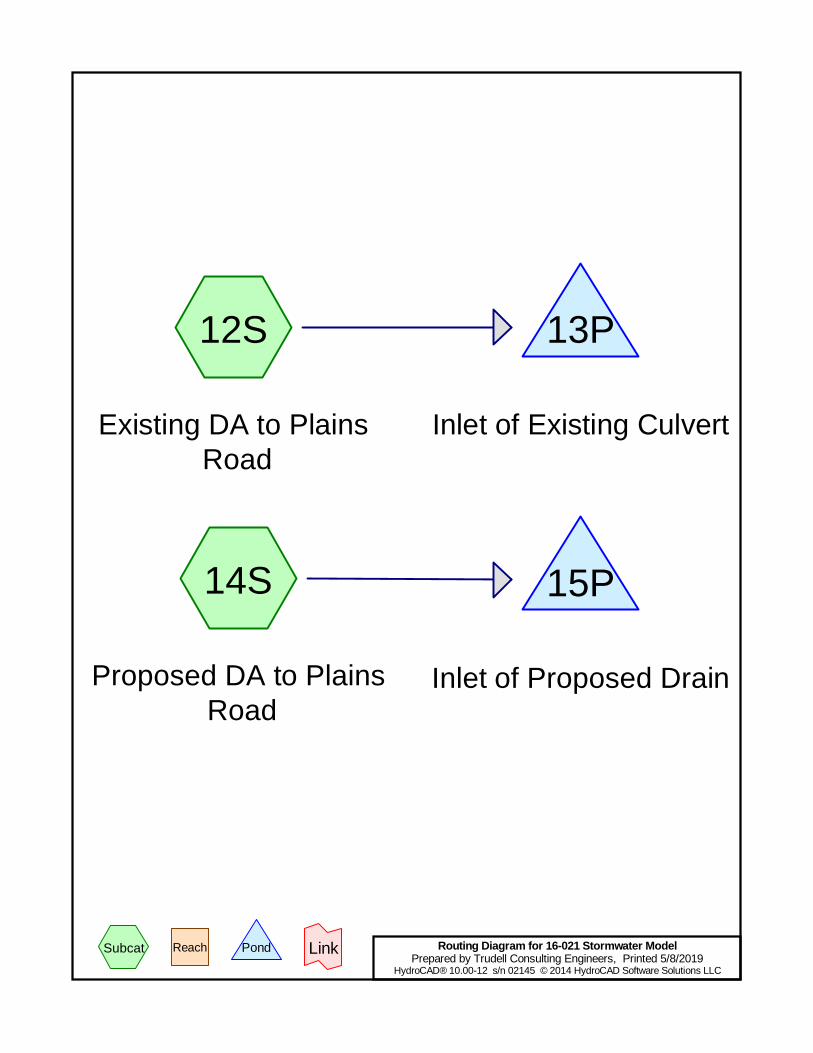
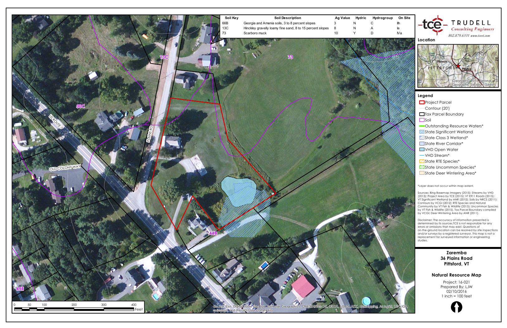
On-site soils are predominately Hydrologic Soil Group (HSG) C, with some HSG Asoils in the northwest corner of the property and some HSG D soils in the northeastcorner of the property. A “Natural Resources Map” illustrating these siteconditions is attached to this report.
4. Existing Stormwater System
Currently, there is no engineered or permitted stormwater system on-site.However, drainage for the property leaves the site in two locations. The majorityof the property, including all existing impervious development, flows to theexisting Class II wet meadow and exits the site through a culvert beneath theneighboring driveway at S/N 001. The remainder of the property flows to thesouthwest corner of the property and northwest through a culvert beneath PlainsRoad and eventually across Route 7 to Otter Creek.
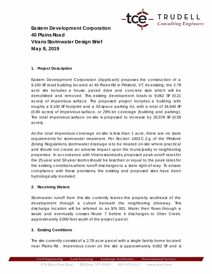
5. Proposed Stormwater System
The proposed site, once developed, will drain to the same two locations ascurrently exist. The paved area will be graded and crowned for water to sheetflow from the driveway entrance, loading dock and northernmost two parkingspaces northwest to the existing grassed area. From there, water will sheet flowto the existing drainage swale, wet meadow, and farm pond where it willinfiltrate into the ground or eventually leave the site through S/N 001.
The remaining majority of the parking area will sheet flow to the south where itwill be directed by a constructed swale off the end of the parking lot. The swaledirects flows back to the wet meadow and farm pond where water will eitherinfiltrate or eventually leave the site through S/N 001. Further, there will be a
Page 3Stormwater Narrative – Eastern Development CorporationMay 8, 2019
timber check dam within the swale to detain flows, allowing for infiltration andcontrolled discharge through small orifices in the dam.
The remainder of the site drainage area which currently flows to the existingculvert crossing Plains Road has been greatly minimized. The existing culvertunder Plains Road will be removed and new HDPE drain pipes and yarddrains/catch basins will be installed. This new drain piping will outlet at thewestern side of Plains Road in the same outlet location as the existing culvert.
6. Stormwater Compliance
As proposed development is less than 1-acre of impervious cover there is nostate regulation for stormwater treatment. However, it should be ensured that theproposed project has no undue adverse impacts to the municipality orsurrounding properties.
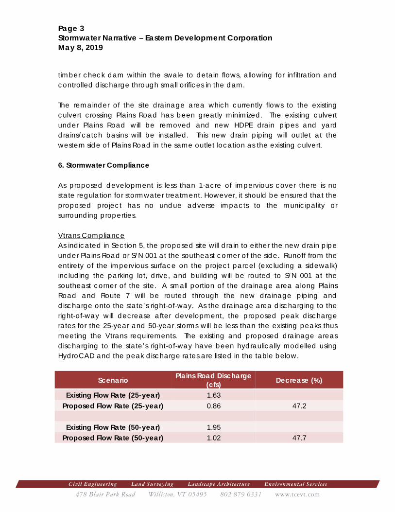
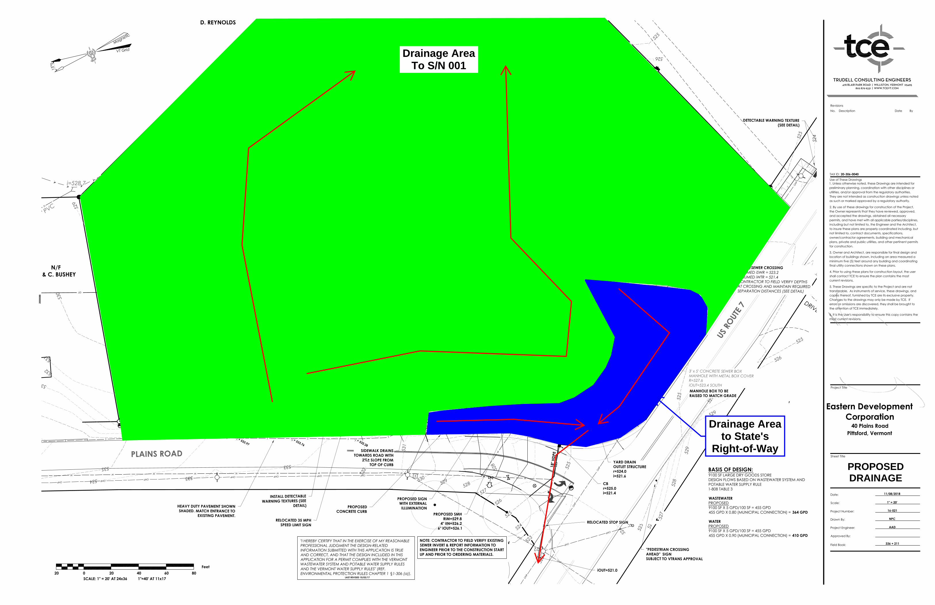
Vtrans ComplianceAs indicated in Section 5, the proposed site will drain to either the new drain pipeunder Plains Road or S/N 001 at the southeast corner of the side. Runoff from theentirety of the impervious surface on the project parcel (excluding a sidewalk)including the parking lot, drive, and building will be routed to S/N 001 at thesoutheast corner of the site. A small portion of the drainage area along PlainsRoad and Route 7 will be routed through the new drainage piping anddischarge onto the state’s right-of-way. As the drainage area discharging to theright-of-way will decrease after development, the proposed peak dischargerates for the 25-year and 50-year storms will be less than the existing peaks thusmeeting the Vtrans requirements. The existing and proposed drainage areasdischarging to the state’s right-of-way have been hydraulically modelled usingHydroCAD and the peak discharge rates are listed in the table below.
Scenario Plains Road Discharge(cfs) Decrease (%)
Existing Flow Rate (25-year) 1.63Proposed Flow Rate (25-year) 0.86 47.2
Existing Flow Rate (50-year) 1.95Proposed Flow Rate (50-year) 1.02 47.7
Page 4Stormwater Narrative – Eastern Development CorporationMay 8, 2019
7. Conclusions
As outlined in the above table, the proposed development will decrease theamount of runoff discharging onto the State’s right-of-way. Additionally, peakstormwater runoff rates for post-development conditions will be reduced for the25-year and 50-year storms, thus meeting the Vtrans stormwater requirements.
Enclosed:25 Year & 50 Year HydroCAD ModelNatural Resources MapExisting Drainage Area MapProposed Drainage Area Map
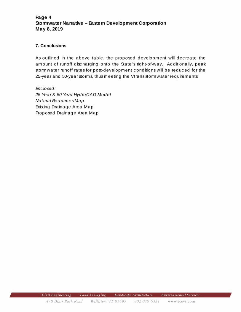
12S
Existing DA to Plains Road
14S
Proposed DA to Plains Road
13P
Inlet of Existing Culvert
15P
Inlet of Proposed Drain
Routing Diagram for 16-021 Stormwater ModelPrepared by Trudell Consulting Engineers, Printed 5/8/2019
HydroCAD® 10.00-12 s/n 02145 © 2014 HydroCAD Software Solutions LLC
Subcat Reach Pond Link
16-021 Stormwater Model Printed 5/8/2019Prepared by Trudell Consulting Engineers
Page 2HydroCAD® 10.00-12 s/n 02145 © 2014 HydroCAD Software Solutions LLC
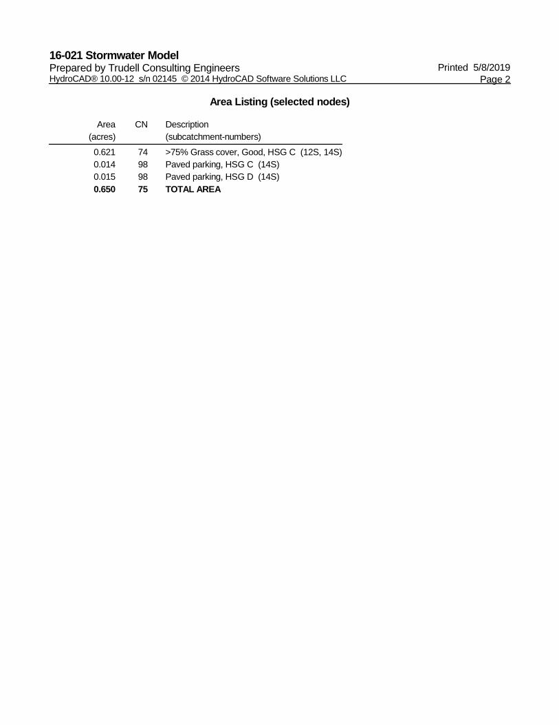
Area Listing (selected nodes)
Area(acres)
CN Description(subcatchment-numbers)
0.621 74 >75% Grass cover, Good, HSG C (12S, 14S)0.014 98 Paved parking, HSG C (14S)0.015 98 Paved parking, HSG D (14S)0.650 75 TOTAL AREA
16-021 Stormwater Model Printed 5/8/2019Prepared by Trudell Consulting Engineers
Page 3HydroCAD® 10.00-12 s/n 02145 © 2014 HydroCAD Software Solutions LLC
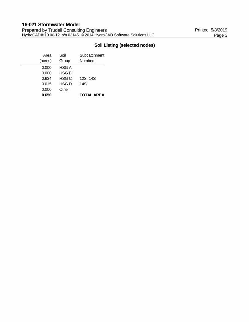
Soil Listing (selected nodes)
Area(acres)
SoilGroup
SubcatchmentNumbers
0.000 HSG A0.000 HSG B0.634 HSG C 12S, 14S0.015 HSG D 14S0.000 Other0.650 TOTAL AREA
16-021 Stormwater Model Printed 5/8/2019Prepared by Trudell Consulting Engineers
Page 4HydroCAD® 10.00-12 s/n 02145 © 2014 HydroCAD Software Solutions LLC
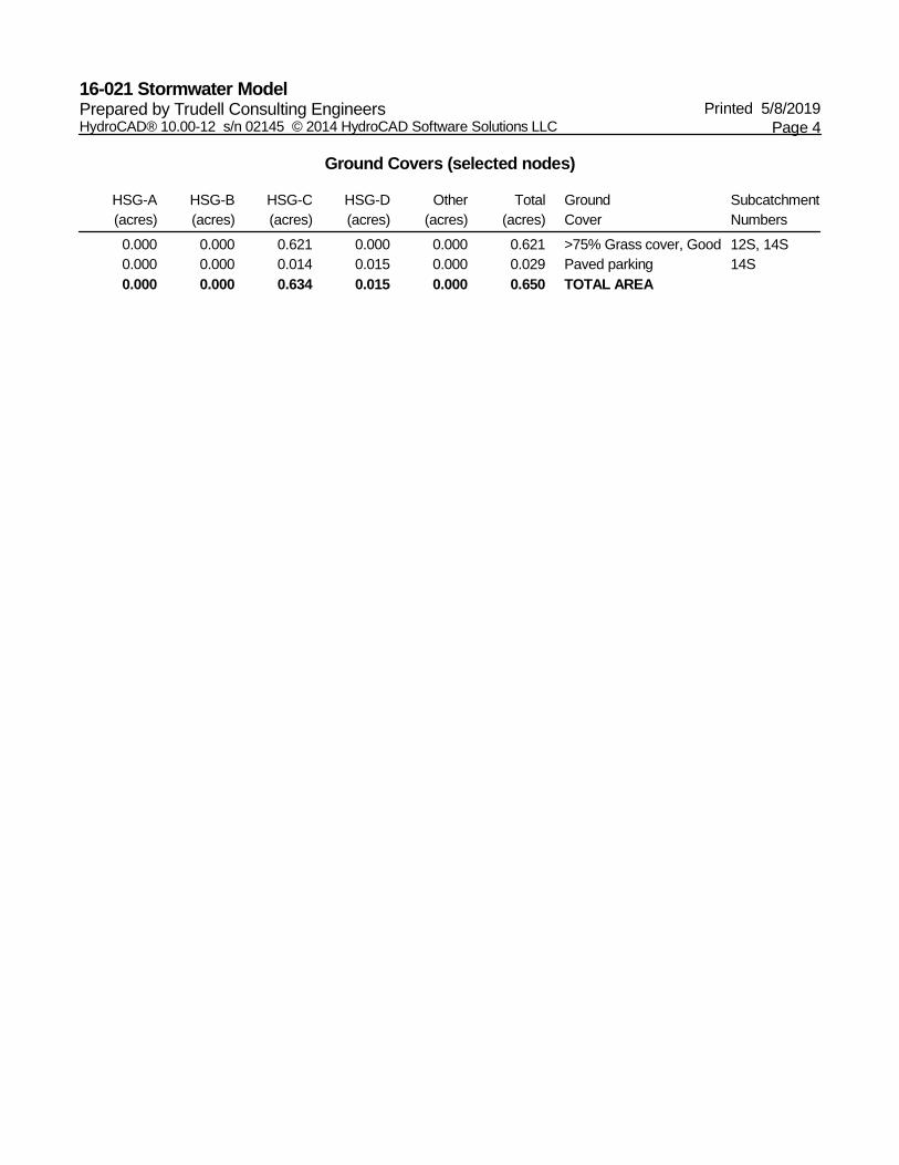
Ground Covers (selected nodes)
HSG-A(acres)
HSG-B(acres)
HSG-C(acres)
HSG-D(acres)
Other(acres)
Total(acres)
GroundCover
SubcatchmentNumbers
0.000 0.000 0.621 0.000 0.000 0.621 >75% Grass cover, Good 12S, 14S0.000 0.000 0.014 0.015 0.000 0.029 Paved parking 14S0.000 0.000 0.634 0.015 0.000 0.650 TOTAL AREA

Type II 24-hr 25-Year Rainfall=4.50"16-021 Stormwater Model Printed 5/8/2019Prepared by Trudell Consulting Engineers
Page 5HydroCAD® 10.00-12 s/n 02145 © 2014 HydroCAD Software Solutions LLC
Time span=0.00-72.00 hrs, dt=0.05 hrs, 1441 pointsRunoff by SCS TR-20 method, UH=SCS, Weighted-Q
Reach routing by Stor-Ind+Trans method - Pond routing by Stor-Ind method
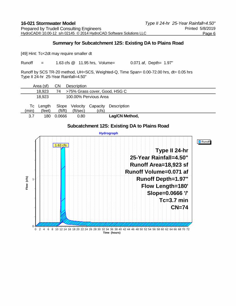
Runoff Area=18,923 sf 0.00% Impervious Runoff Depth=1.97"Subcatchment 12S: Existing DA to Plains Road Flow Length=180' Slope=0.0666 '/' Tc=3.7 min CN=74 Runoff=1.63 cfs 0.071 af
Runoff Area=9,380 sf 13.54% Impervious Runoff Depth=2.28"Subcatchment 14S: Proposed DA to Plains Road Flow Length=150' Slope=0.0266 '/' Tc=4.7 min CN=77 Runoff=0.86 cfs 0.041 af
Inflow=1.63 cfs 0.071 afPond 13P: Inlet of Existing Culvert Primary=1.63 cfs 0.071 af
Inflow=0.86 cfs 0.041 afPond 15P: Inlet of Proposed Drain Primary=0.86 cfs 0.041 af
Total Runoff Area = 0.650 ac Runoff Volume = 0.112 af Average Runoff Depth = 2.08"95.51% Pervious = 0.621 ac 4.49% Impervious = 0.029 ac
Type II 24-hr 25-Year Rainfall=4.50"16-021 Stormwater Model Printed 5/8/2019Prepared by Trudell Consulting Engineers
Page 6HydroCAD® 10.00-12 s/n 02145 © 2014 HydroCAD Software Solutions LLC
Summary for Subcatchment 12S: Existing DA to Plains Road
[49] Hint: Tc<2dt may require smaller dt
Runoff = 1.63 cfs @ 11.95 hrs, Volume= 0.071 af, Depth= 1.97"
Runoff by SCS TR-20 method, UH=SCS, Weighted-Q, Time Span= 0.00-72.00 hrs, dt= 0.05 hrsType II 24-hr 25-Year Rainfall=4.50"
Area (sf) CN Description18,923 74 >75% Grass cover, Good, HSG C18,923 100.00% Pervious Area
Tc Length Slope Velocity Capacity Description(min) (feet) (ft/ft) (ft/sec) (cfs)
3.7 180 0.0666 0.80 Lag/CN Method,
Subcatchment 12S: Existing DA to Plains Road
Runoff
Hydrograph
Time (hours)727068666462605856545250484644424038363432302826242220181614121086420
Flow
(cfs
)
1
0
Type II 24-hr25-Year Rainfall=4.50"Runoff Area=18,923 sf
Runoff Volume=0.071 afRunoff Depth=1.97"
Flow Length=180'Slope=0.0666 '/'
Tc=3.7 minCN=74
1.63 cfs
Type II 24-hr 25-Year Rainfall=4.50"16-021 Stormwater Model Printed 5/8/2019Prepared by Trudell Consulting Engineers
Page 7HydroCAD® 10.00-12 s/n 02145 © 2014 HydroCAD Software Solutions LLC
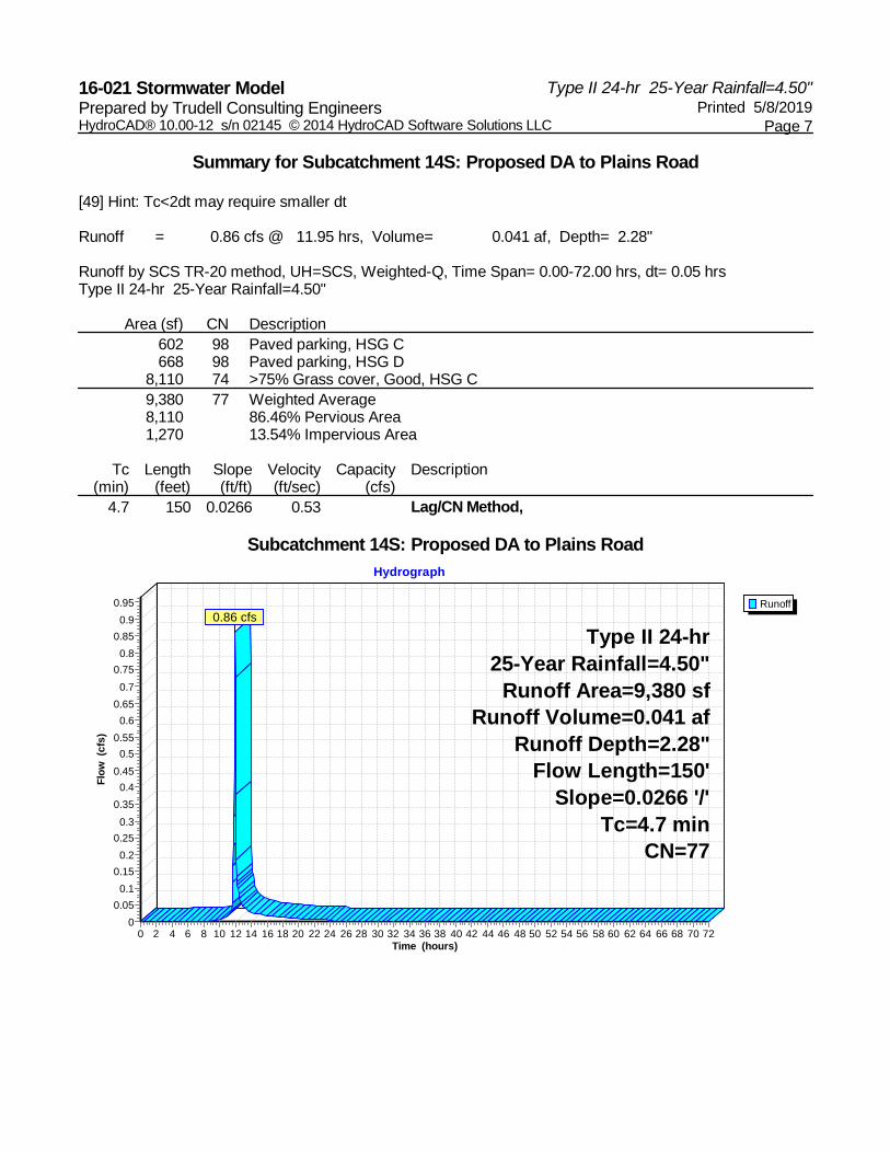
Summary for Subcatchment 14S: Proposed DA to Plains Road
[49] Hint: Tc<2dt may require smaller dt
Runoff = 0.86 cfs @ 11.95 hrs, Volume= 0.041 af, Depth= 2.28"
Runoff by SCS TR-20 method, UH=SCS, Weighted-Q, Time Span= 0.00-72.00 hrs, dt= 0.05 hrsType II 24-hr 25-Year Rainfall=4.50"
Area (sf) CN Description602 98 Paved parking, HSG C668 98 Paved parking, HSG D
8,110 74 >75% Grass cover, Good, HSG C9,380 77 Weighted Average8,110 86.46% Pervious Area1,270 13.54% Impervious Area
Tc Length Slope Velocity Capacity Description(min) (feet) (ft/ft) (ft/sec) (cfs)
4.7 150 0.0266 0.53 Lag/CN Method,
Subcatchment 14S: Proposed DA to Plains Road
Runoff
Hydrograph
Time (hours)727068666462605856545250484644424038363432302826242220181614121086420
Flow
(cfs
)
0.950.9
0.850.8
0.750.7
0.650.6
0.550.5
0.450.4
0.350.3
0.250.2
0.150.1
0.050
Type II 24-hr25-Year Rainfall=4.50"
Runoff Area=9,380 sfRunoff Volume=0.041 af
Runoff Depth=2.28"Flow Length=150'
Slope=0.0266 '/'Tc=4.7 min
CN=77
0.86 cfs

Type II 24-hr 25-Year Rainfall=4.50"16-021 Stormwater Model Printed 5/8/2019Prepared by Trudell Consulting Engineers
Page 8HydroCAD® 10.00-12 s/n 02145 © 2014 HydroCAD Software Solutions LLC
Summary for Pond 13P: Inlet of Existing Culvert
[40] Hint: Not Described (Outflow=Inflow)
Inflow Area = 0.434 ac, 0.00% Impervious, Inflow Depth = 1.97" for 25-Year eventInflow = 1.63 cfs @ 11.95 hrs, Volume= 0.071 afPrimary = 1.63 cfs @ 11.95 hrs, Volume= 0.071 af, Atten= 0%, Lag= 0.0 min
Routing by Stor-Ind method, Time Span= 0.00-72.00 hrs, dt= 0.05 hrs
Pond 13P: Inlet of Existing Culvert
InflowPrimary
Hydrograph
Time (hours)727068666462605856545250484644424038363432302826242220181614121086420
Flow
(cfs
)
1
0
Inflow Area=0.434 ac1.63 cfs
1.63 cfs
Type II 24-hr 25-Year Rainfall=4.50"16-021 Stormwater Model Printed 5/8/2019Prepared by Trudell Consulting Engineers
Page 9HydroCAD® 10.00-12 s/n 02145 © 2014 HydroCAD Software Solutions LLC
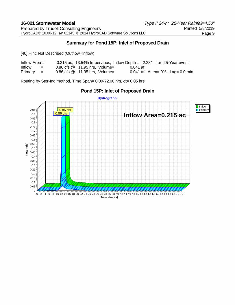
Summary for Pond 15P: Inlet of Proposed Drain
[40] Hint: Not Described (Outflow=Inflow)
Inflow Area = 0.215 ac, 13.54% Impervious, Inflow Depth = 2.28" for 25-Year eventInflow = 0.86 cfs @ 11.95 hrs, Volume= 0.041 afPrimary = 0.86 cfs @ 11.95 hrs, Volume= 0.041 af, Atten= 0%, Lag= 0.0 min
Routing by Stor-Ind method, Time Span= 0.00-72.00 hrs, dt= 0.05 hrs
Pond 15P: Inlet of Proposed Drain
InflowPrimary
Hydrograph
Time (hours)727068666462605856545250484644424038363432302826242220181614121086420
Flow
(cfs
)
0.950.9
0.850.8
0.750.7
0.650.6
0.550.5
0.450.4
0.350.3
0.250.2
0.150.1
0.050
Inflow Area=0.215 ac0.86 cfs
0.86 cfs
Type II 24-hr 50-Year Rainfall=5.00"16-021 Stormwater Model Printed 5/8/2019Prepared by Trudell Consulting Engineers
Page 10HydroCAD® 10.00-12 s/n 02145 © 2014 HydroCAD Software Solutions LLC
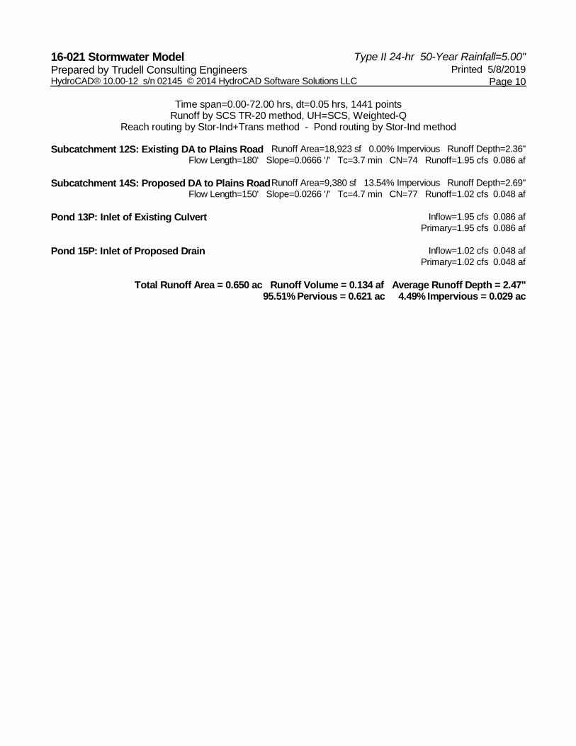
Time span=0.00-72.00 hrs, dt=0.05 hrs, 1441 pointsRunoff by SCS TR-20 method, UH=SCS, Weighted-Q
Reach routing by Stor-Ind+Trans method - Pond routing by Stor-Ind method
Runoff Area=18,923 sf 0.00% Impervious Runoff Depth=2.36"Subcatchment 12S: Existing DA to Plains Road Flow Length=180' Slope=0.0666 '/' Tc=3.7 min CN=74 Runoff=1.95 cfs 0.086 af
Runoff Area=9,380 sf 13.54% Impervious Runoff Depth=2.69"Subcatchment 14S: Proposed DA to Plains Road Flow Length=150' Slope=0.0266 '/' Tc=4.7 min CN=77 Runoff=1.02 cfs 0.048 af
Inflow=1.95 cfs 0.086 afPond 13P: Inlet of Existing Culvert Primary=1.95 cfs 0.086 af
Inflow=1.02 cfs 0.048 afPond 15P: Inlet of Proposed Drain Primary=1.02 cfs 0.048 af
Total Runoff Area = 0.650 ac Runoff Volume = 0.134 af Average Runoff Depth = 2.47"95.51% Pervious = 0.621 ac 4.49% Impervious = 0.029 ac

Type II 24-hr 50-Year Rainfall=5.00"16-021 Stormwater Model Printed 5/8/2019Prepared by Trudell Consulting Engineers
Page 11HydroCAD® 10.00-12 s/n 02145 © 2014 HydroCAD Software Solutions LLC
Summary for Subcatchment 12S: Existing DA to Plains Road
[49] Hint: Tc<2dt may require smaller dt
Runoff = 1.95 cfs @ 11.94 hrs, Volume= 0.086 af, Depth= 2.36"
Runoff by SCS TR-20 method, UH=SCS, Weighted-Q, Time Span= 0.00-72.00 hrs, dt= 0.05 hrsType II 24-hr 50-Year Rainfall=5.00"
Area (sf) CN Description18,923 74 >75% Grass cover, Good, HSG C18,923 100.00% Pervious Area
Tc Length Slope Velocity Capacity Description(min) (feet) (ft/ft) (ft/sec) (cfs)
3.7 180 0.0666 0.80 Lag/CN Method,
Subcatchment 12S: Existing DA to Plains Road
Runoff
Hydrograph
Time (hours)727068666462605856545250484644424038363432302826242220181614121086420
Flow
(cfs
)
2
1
0
Type II 24-hr50-Year Rainfall=5.00"Runoff Area=18,923 sf
Runoff Volume=0.086 afRunoff Depth=2.36"
Flow Length=180'Slope=0.0666 '/'
Tc=3.7 minCN=74
1.95 cfs
Type II 24-hr 50-Year Rainfall=5.00"16-021 Stormwater Model Printed 5/8/2019Prepared by Trudell Consulting Engineers
Page 12HydroCAD® 10.00-12 s/n 02145 © 2014 HydroCAD Software Solutions LLC
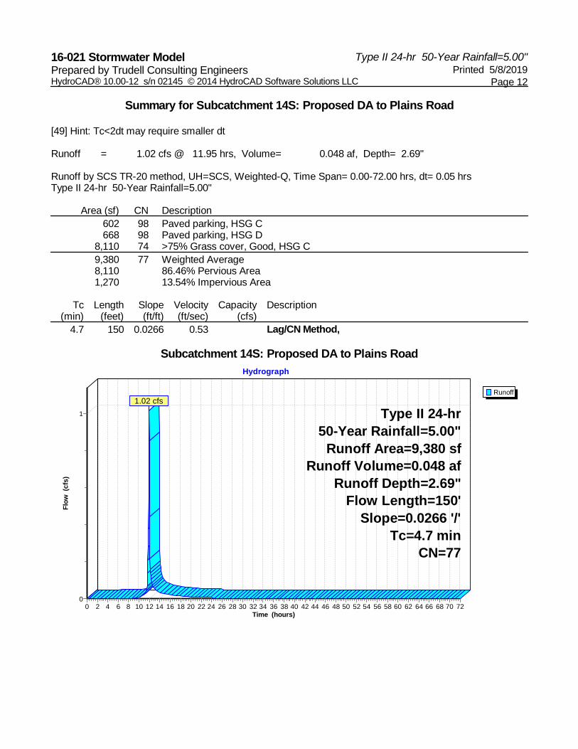
Summary for Subcatchment 14S: Proposed DA to Plains Road
[49] Hint: Tc<2dt may require smaller dt
Runoff = 1.02 cfs @ 11.95 hrs, Volume= 0.048 af, Depth= 2.69"
Runoff by SCS TR-20 method, UH=SCS, Weighted-Q, Time Span= 0.00-72.00 hrs, dt= 0.05 hrsType II 24-hr 50-Year Rainfall=5.00"
Area (sf) CN Description602 98 Paved parking, HSG C668 98 Paved parking, HSG D
8,110 74 >75% Grass cover, Good, HSG C9,380 77 Weighted Average8,110 86.46% Pervious Area1,270 13.54% Impervious Area
Tc Length Slope Velocity Capacity Description(min) (feet) (ft/ft) (ft/sec) (cfs)
4.7 150 0.0266 0.53 Lag/CN Method,
Subcatchment 14S: Proposed DA to Plains Road
Runoff
Hydrograph
Time (hours)727068666462605856545250484644424038363432302826242220181614121086420
Flow
(cfs
)
1
0
Type II 24-hr50-Year Rainfall=5.00"
Runoff Area=9,380 sfRunoff Volume=0.048 af
Runoff Depth=2.69"Flow Length=150'
Slope=0.0266 '/'Tc=4.7 min
CN=77
1.02 cfs
Type II 24-hr 50-Year Rainfall=5.00"16-021 Stormwater Model Printed 5/8/2019Prepared by Trudell Consulting Engineers
Page 13HydroCAD® 10.00-12 s/n 02145 © 2014 HydroCAD Software Solutions LLC
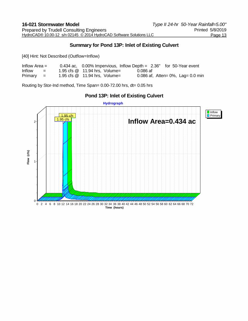
Summary for Pond 13P: Inlet of Existing Culvert
[40] Hint: Not Described (Outflow=Inflow)
Inflow Area = 0.434 ac, 0.00% Impervious, Inflow Depth = 2.36" for 50-Year eventInflow = 1.95 cfs @ 11.94 hrs, Volume= 0.086 afPrimary = 1.95 cfs @ 11.94 hrs, Volume= 0.086 af, Atten= 0%, Lag= 0.0 min
Routing by Stor-Ind method, Time Span= 0.00-72.00 hrs, dt= 0.05 hrs
Pond 13P: Inlet of Existing Culvert
InflowPrimary
Hydrograph
Time (hours)727068666462605856545250484644424038363432302826242220181614121086420
Flow
(cfs
)
2
1
0
Inflow Area=0.434 ac1.95 cfs
1.95 cfs
Type II 24-hr 50-Year Rainfall=5.00"16-021 Stormwater Model Printed 5/8/2019Prepared by Trudell Consulting Engineers
Page 14HydroCAD® 10.00-12 s/n 02145 © 2014 HydroCAD Software Solutions LLC
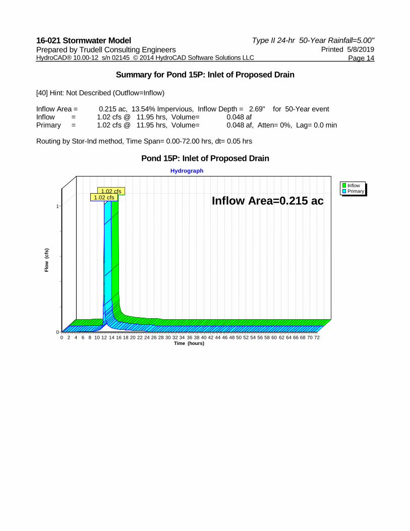
Summary for Pond 15P: Inlet of Proposed Drain
[40] Hint: Not Described (Outflow=Inflow)
Inflow Area = 0.215 ac, 13.54% Impervious, Inflow Depth = 2.69" for 50-Year eventInflow = 1.02 cfs @ 11.95 hrs, Volume= 0.048 afPrimary = 1.02 cfs @ 11.95 hrs, Volume= 0.048 af, Atten= 0%, Lag= 0.0 min
Routing by Stor-Ind method, Time Span= 0.00-72.00 hrs, dt= 0.05 hrs
Pond 15P: Inlet of Proposed Drain
InflowPrimary
Hydrograph
Time (hours)727068666462605856545250484644424038363432302826242220181614121086420
Flow
(cfs
)
1
0
Inflow Area=0.215 ac1.02 cfs
1.02 cfs
520
500
480
540
460
540
66B
73
30C
13C
13C
65E
US ROUTE 7
PLAIN
S RD
OLD COLONY WAY
Source: Esri, DigitalGlobe, GeoEye, Earthstar Geographics, CNES/Airbus DS, USDA, USGS, AEX, Getmapping, Aerogrid, IGN, IGP,swisstopo, and the GIS User Community
Location
Zaremba36 Plains Road
Pittsford, VT
Natural Resource Map
_̂
Copyright:© 2013 NationalGeographic Society, i-cubed
Project ParcelContour (20')Tax Parcel BoundarySoilOutstanding Resource Waters*State Significant WetlandState Class 3 Wetland*State River Corridor*VHD Open WaterVHD Stream*State RTE Species*State Uncommon Species*State Deer Wintering Area*
*Layer does not occur within map extent.
Sources: Bing Basemap Imagery (2015); Streams by VHD (2013); Project Area by TCE (2015); VT E911 Roads (2015); VT Significant Wetland by ANR (2010); Soils by NRCS (2011);Contours by VCGI (2012); RTE Species and Natural Community by VT Fish & Wildlife (2015); Uncommon Species by VT Fish & Wildlife (2015). Tax Parcel Boundary compiled by VCGI; Deer Wintering Area by ANR (2011).
Disclaimer: The accuracy of information presented is determined by its sources.TCE is not responsible for any errors or omissions that may exist. Questions of on-the-ground location can be resolved by site inspections and/or surveys by a registered surveyor. This map is not areplacement for surveyed information or engineering studies.
Legend
Project: 16-021Prepared By: LJW
02/10/20161 inch = 100 feet
802.879.6331 www.tcevt.com
[0 100 200 300 40050Feet
Soil Key Soil Description Ag Value Hydric Hydrogroup On Site66B Georgia and Amenia soils, 3 to 8 percent slopes 3 N C IIh13C Hinckley gravelly loamy fine sand, 8 to 15 percent slopes 8 N A Ia73 Scarboro muck 10 Y D IVa
536
536 53
5
535
53553
4
534
534
534
534
533
533
533
533
533
533
532
532
532
532
532
531
531
531
531
531
530
530
530
530
530
529 529
529
529
529
529
529
528
528 528
528
528
528
528
528
528
527
527 527
527
527
527
527
527
527
527527
527
527
526526
526
526
526
526
526
526
526
526
526
526
525
525
525
525
525
525
525
525
525
525
525
525
525
525
525
525
524
524
524
524
524
524
524
524
524
523
523
523
523
522
522
522
522
15" CMP
W
W
W
W
W
OHP
OHP
OHP
OHP
OHP
OHP
OHP
OHP
OHP
OHP
S
D D D D
OHP OHP OHP OHP OHP OHP OHP OHP
OHP
GUY
i=528.7
HOUSE
EXISTING WIRE FENCE
SWALE
SWAL
E
GARAGE
DRI
VEW
AY
EXIS
TING
WIR
E FE
NC
E
DRIV
EWA
Y24" SPRUCE
30" MAPLE
30" MAPLE
24" SPRUCE
40" LOCUST
CLASS IIWETLAND
6" CLAY TILE
PAVED DRIVE
4" PVC
SWA
LE
SEASONAL DRAINAGE SWALE
LILACBUSHESTBR
14" MAPLE
24" MAPLE
30" MAPLE
12" BIRCH
20"MAPLE
42" MAPLE
36" MAPLE
PORC
HHOUSE TO BEREMOVED
HOUSE
i=521.15 i=521.97
i=526.42
i=526.19
12" CMP
STOP SIGN
24,000 LEGAL LOAD LIMIT
BRACE POLE
35 M.P.H. TO BE RELOCATED
APPROXIMATE SEWER LOCATIONTO BE REMOVED
APPROXIMATEWATER LOCATION
3' x 5' CONCRETE SEWER BOXMANHOLE WITH METAL BOX COVER
R=527.6iOUT=523.4 SOUTH
US ROUTE 7
PLAINS ROAD
FARM PONDWSE = 524.30
D
SS
REMOVE30" STUMP
12" BIRCH
W
W
W
WW
WATER SERVICE AND CURB STOPTO BE REMOVED
16" SPRUCE
CONCRETE SLABTO BE REMOVED
WOODEN STREAM CROSSING
50' W
ETLA
ND
BUFF
ER
6" CLAY TILE
W
W
W
W
W
W
W
W
W
2" TREEHEDGEROW
3' x 5' CONCRETE SEWER BOXMANHOLE WITH METAL BOX COVER
CLASS IIIWETLAND
EXISTING SIDEWALK
HYDRANT &VALVE
MAILBOX
PAVED DRIVE
TO BE RM
OVED
GRAVEL TBR
C.S.
C.S.
HYD.
S
S
S
S
S
S
S
S
S
S
S
6" CLAY TILE
N/FM. RAWLINGS
N/FM. & M. BLANCHARD
N/FD. REYNOLDS
N/FR. & C. BUSHEY
N/F TOWN OFPITTSFORD
SCHOOL DISTRICT
N/FD. & J. QUERREY
PROJECT DEMARCATION FENCEMARK EDGE OF WETLAND IMPACTWITH SNOW FENCE PRIOR TO CONSTRUCTION
2000
088
No. Description Date By
Revisions
478 BLAIR PARK ROAD | WILLISTON, VERMONT 05495
802 879 6331 | WWW.TCEVT.COM
TRUDELL CONSULTING ENGINEERS
No. 9020CIVIL
AB
I GA I L A . D
ER
Y
S TA T E OF V E RMON
T
PRO
F E S S I ONA L ENG
I NE E
R
L I C E N S E D
Sheet Title
Project Title
Use of These Drawings1. Unless otherwise noted, these Drawings are intended forpreliminary planning, coordination with other disciplines orutilities, and/or approval from the regulatory authorities. They are not intended as construction drawings unless notedas such or marked approved by a regulatory authority.
2. By use of these drawings for construction of the Project,the Owner represents that they have reviewed, approved,and accepted the drawings, obtained all necessarypermits, and have met with all applicable parties/disciplines,including but not limited to, the Engineer and the Architect,to insure these plans are properly coordinated including, butnot limited to, contract documents, specifications,owner/contractor agreements, building and mechanicalplans, private and public utilities, and other pertinent permitsfor construction.
3. Owner and Architect, are responsible for final design andlocation of buildings shown, including an area measured aminimum five (5) feet around any building and coordinatingfinal utility connections shown on these plans.
4. Prior to using these plans for construction layout, the usershall contact TCE to ensure the plan contains the mostcurrent revisions.
5. These Drawings are specific to the Project and are nottransferable. As instruments of service, these drawings, andcopies thereof, furnished by TCE are its exclusive property. Changes to the drawings may only be made by TCE. Iferrors or omissions are discovered, they shall be brought tothe attention of TCE immediately.
6. It is the User's responsibility to ensure this copy contains themost current revisions.
Scale:
Project Number:
Date:
Drawn By:
Project Engineer:
Approved By:
Field Book:
TAX ID:
Existing Conditions& Demolition Plan
C1-02
11/08/2018
1" = 30'
16-021
NPC
AAD
336 + 211
Eastern DevelopmentCorporation
40 Plains RoadPittsford, Vermont
20-306-0040
0Feet
30 30 60 90 120SCALE: 1" = 30' AT 24x36 1"=60' AT 11x17
1 12/04/18 AADUpdate Demolition Items
S/N 001ExistingDrainage Area
to S/N 001
Existing DrainageArea to State'sRight-of-Way
ExistingDrainage
535
534
534
534
534
533
533
533
533
533
533
532
532
532
532
532
531
531
531
531
531
530
530
530
530
530
529
529
529
529
529
529
529
528
528
528
528
528
528
528
528
528
527
527
527
527
527
527
527
527
527
527
527
527
526
526
526
526
526
526
526
526
526
526
525
525
525
525
525
525
525
525
525
525
525
524
524
524
524
523
523
522
522
W
W
W
W
W
W
W
W
OHP
OHP
OHP
OHP
OHP
OHP
OHP
OHPOHPOHPOHPOHPOHPOHPOHPOHP
S
OHP
OHP
OHP
OHP
OHP
OHP
OHP
OHP
OHP
OHP
OHP
OHPi=528.7
GARA
GE
DRIVEWAY
DRIVEWAY
PAVED DRIVE
4" PVC
SEASONAL D
RAINAGE SWALE
HOUS
Ei=526.42
i=526.1912" CMP
US R
OUTE 7
PLAINS ROAD
D
WW
WWWWWWWWWW
S S S S S S S SS
S
S
S
S
S
N/F BAPTISTCEMETERY
D. KEITH, ET AL
N/FM. RAWLINGS
D. REYNOLDS
N/FR. & C. BUSHEY
PROPOSED SIGNWITH EXTERNALILLUMINATION
36'
20'
20'
18'x18' CONCRETEDUMPSTER PAD
PROVIDE 12'x10'DUMPSTER ENCLOSURE
PER ARCHITECT
PROPOSEDCONCRETE
LOADING PAD
PROPOSEDBUILDINGFFE=532.0
16
12'x13' FENCEDCONCRETE PADABOVE GROUNDPROPANE TANKSWITH BOARD ON
BOARD FENCEENCLOSURE WITH
BOLLARDS ONEACH CORNER
i=528.0
CONCRETESIDEWALK
PROPOSED 6.5'TALL STOCKADEFENCE
HEAVY DUTY PAVEMENT SHOWNSHADED. MATCH ENTRANCE TO
EXISTING PAVEMENT.RELOCATED 35 MPH
SPEED LIMIT SIGN
NEWGRAVEL
ACCESSIBLE PARKINGSEE DETAIL
MAIN ENTRYUD UD UD UD UD UD UD UD UD
UD
8" PVC
BOLLARD (TYP.)DROP CURB
PROVIDE 2-3: ELECTRICALCONDUITS - SEE ARCHITECTPLAN FOR METER LOCATION
TOOLED JOINT 5 FT O/CEXPANSION JOINT 45'SPACING CONTRACTIONJOINT 15' O/C
i=526.3 i=525.5
DAYLIGHT 12" PVCROOF DRAIN, WITHSPASH PAD
5' W
IDE C
ONCRETE
SIDE
WALK
DETECTABLE WARNING TEXTURE(SEE DETAIL)
INSTALL DETECTABLEWARNING TEXTURES (SEE
DETAIL)
C.S.
1-1/2" TYPE K COPPER
4" PVC SDR 35+ 533.97
+ 533.76+ 532.28
PROPOSED SMHRIM=529.8
4" iIN=526.26" iOUT=526.1
5 FT CONCRETE SIDEWALK
GG
G G
TBM"X" CHISEL MARK ONNORTH BONET BOLTELEV. =528.65
+530.88
+530.88
529.25 +
527.
2+
+528.8
+528.8
+528.9
BOULDER WALLTW:531.82BW:529.0±
+ 532.92
+ 53
2.82
531.
32+
+531
.82
531.
32+
+531
.82
531.
32+
+531
.82
531.
5 +
531.
32+
+531
.82
531.
02+
RIPRAP 2x8
+530.42
531.1+
530.22+
TIMBER DAM
D
D
D
528.
5+
528.5
+
+527
.75
EXISTINGGRAVELPAD
W
W
W
W
RELOCATED STOP SIGN
PROPOSED ROW
iOUT=521.0
SNOWSTORAGE
"PEDESTRIAN CROSSINGAHEAD" SIGNSUBJECT TO VTRANS APPROVAL
CBr=525.0i=521.4
YARD DRAINOUTLET STRUCTUREr=524.0i=521.6
3' x 5' CONCRETE SEWER BOXMANHOLE WITH METAL BOX COVERR=527.6iOUT=523.4 SOUTH
SIDEWALK DRAINSTOWARDS ROAD WITH
2%± SLOPE FROMTOP OF CURB
R65'
R40'
12" HDPE
18" H
DPE
15'x75' LOADING ZONE
PROPOSEDCONCRETE CURB
SAWCUT
PROPOSEDSTRIPED
CROSSWALKSUBJECT TO
VTRANSAPPROVAL
532
531
528
530531
533
531 530
526
527
528
531
530
532
524
CONNECTFENCE TOBUILDING WITHGATE
WATER/SEWER CROSSINGASSUMED iSWR = 523.2ASSUMED iWTR = 521.4CONTRACTOR TO FIELD VERIFY DEPTHSAT CROSSING AND MAINTAIN REQUIREDSEPARATION DISTANCES (SEE DETAIL)
S
S
2
++
+
+ + + + ++
++
++
++
++
++
++
+++
++
++
++
++
+++
2000
088
No. Description Date By
Revisions
478 BLAIR PARK ROAD | WILLISTON, VERMONT 05495
802 879 6331 | WWW.TCEVT.COM
TRUDELL CONSULTING ENGINEERS
No. 7637CIVIL
JE
R EMY M . MA T OS K
Y
S TA T E OF V E RMON
T
PRO
F E S S I ONA L ENG
I NE E
R
L I C E N S E D
Sheet Title
Project Title
Use of These Drawings1. Unless otherwise noted, these Drawings are intended forpreliminary planning, coordination with other disciplines orutilities, and/or approval from the regulatory authorities. They are not intended as construction drawings unless notedas such or marked approved by a regulatory authority.
2. By use of these drawings for construction of the Project,the Owner represents that they have reviewed, approved,and accepted the drawings, obtained all necessarypermits, and have met with all applicable parties/disciplines,including but not limited to, the Engineer and the Architect,to insure these plans are properly coordinated including, butnot limited to, contract documents, specifications,owner/contractor agreements, building and mechanicalplans, private and public utilities, and other pertinent permitsfor construction.
3. Owner and Architect, are responsible for final design andlocation of buildings shown, including an area measured aminimum five (5) feet around any building and coordinatingfinal utility connections shown on these plans.
4. Prior to using these plans for construction layout, the usershall contact TCE to ensure the plan contains the mostcurrent revisions.
5. These Drawings are specific to the Project and are nottransferable. As instruments of service, these drawings, andcopies thereof, furnished by TCE are its exclusive property. Changes to the drawings may only be made by TCE. Iferrors or omissions are discovered, they shall be brought tothe attention of TCE immediately.
6. It is the User's responsibility to ensure this copy contains themost current revisions.
Scale:
Project Number:
Date:
Drawn By:
Project Engineer:
Approved By:
Field Book:
TAX ID:
Grading & Utility Plan
C2-02
11/08/2018
1" = 20'
16-021
NPC
AAD
336 + 211
Eastern DevelopmentCorporation
40 Plains RoadPittsford, Vermont
0Feet
20 20 40 60 80SCALE: 1" = 20' AT 24x36 1"=40' AT 11x17
20-306-0040
NOTE: CONTRACTOR TO FIELD VERIFY EXISTINGSEWER INVERT & REPORT INFORMATION TOENGINEER PRIOR TO THE CONSTRUCTION STARTUP AND PRIOR TO ORDERING MATERIALS.
MANHOLE BOX TO BERAISED TO MATCH GRADE
BASIS OF DESIGN:9100 SF LARGE DRY GOODS STOREDESIGN FLOWS BASED ON WASTEWATER SYSTEM ANDPOTABLE WATER SUPPLY RULE1-808 TABLE 3
WASTEWATERPROPOSED9100 SF X 5 GPD/100 SF = 455 GPD455 GPD X 0.80 (MUNICIPAL CONNECTION) = 364 GPD
WATERPROPOSED9100 SF X 5 GPD/100 SF = 455 GPD455 GPD X 0.90 (MUNICIPAL CONNECTION) = 410 GPD
"I HEREBY CERTIFY THAT IN THE EXERCISE OF MY REASONABLEPROFESSIONAL JUDGMENT THE DESIGN-RELATEDINFORMATION SUBMITTED WITH THIS APPLICATION IS TRUEAND CORRECT, AND THAT THE DESIGN INCLUDED IN THISAPPLICATION FOR A PERMIT COMPLIES WITH THE VERMONTWASTEWATER SYSTEM AND POTABLE WATER SUPPLY RULESAND THE VERMONT WATER SUPPLY RULES" (REF.ENVIRONMENTAL PROTECTION RULES CHAPTER 1 §1-306 (a)).
LAST REVISED 10/03/17
1 12/04/18 AADRelocate Building, Sidewalk &Parking
2 2/8/19 JMMSettlement Agreement
Drainage AreaTo S/N 001
Drainage Areato State's
Right-of-WayPROPOSEDDRAINAGE