Embed Size (px)
Citation preview

Manual No: 577013-873 ● Revision: C
Troubleshooting Guide
Vacuum Sensor System

ii
Notice
Veeder-Root makes no warranty of any kind with regard to this publication, including, but not limited to, the implied warranties ofmerchantability and fitness for a particular purpose.
Veeder-Root shall not be liable for errors contained herein or for incidental or consequential damages in connection with the furnishing,performance, or use of this publication.
Veeder-Root reserves the right to change system options or features, or the information contained in this publication.
This publication contains proprietary information which is protected by copyright. All rights reserved. No part of this publication may bephotocopied, reproduced, or translated to another language without the prior written consent of Veeder-Root.
Contact TLS Systems Technical Support for additional troubleshooting information at 800-323-1799.
DAMAGE CLAIMS / LOST EQUIPMENT
Thoroughly examine all components and units as soon as they are received. If any cartons are damaged or missing, write a completeand detailed description of the damage or shortage on the face of the freight bill. The carrier's agent must verify the inspection and signthe description. Refuse only the damaged product, not the entire shipment.
Veeder-Root must be notified of any damages and/or shortages within 30 days of receipt of the shipment, as stated in our Terms andConditions.
VEEDER-ROOT’S PREFERRED CARRIER
1. Contact Veeder-Root Customer Service at 800-873-3313 with the specific part numbers and quantities that were missing orreceived damaged.
2. Fax signed Bill of Lading (BOL) to Veeder-Root Customer Service at 800-234-5350.
3. Veeder-Root will file the claim with the carrier and replace the damaged/missing product at no charge to the customer. CustomerService will work with production facility to have the replacement product shipped as soon as possible.
CUSTOMER’S PREFERRED CARRIER
1. It is the customer’s responsibility to file a claim with their carrier.
2. Customer may submit a replacement purchase order. Customer is responsible for all charges and freight associated withreplacement order. Customer Service will work with production facility to have the replacement product shipped as soon aspossible.
3. If “lost” equipment is delivered at a later date and is not needed, Veeder-Root will allow a Return to Stock without a restocking fee.
4. Veeder-Root will NOT be responsible for any compensation when a customer chooses their own carrier.
RETURN SHIPPING
For the parts return procedure, please follow the appropriate instructions in the "General Returned Goods Policy” pages in the"Policies and Literature" section of the Veeder-Root North American Environmental Products price list. Veeder-Root will not acceptany return product without a Return Goods Authorization (RGA) number clearly printed on the outside of the package.
©Veeder-Root 2008. All rights reserved.

Table of Contents
iii
IntroductionHardware Requirements for Vac Sensors - Verifying Installation .....................................1Safety Precautions ............................................................................................................1
Vac System OverviewConnecting Pump Control Field Wiring to TLS Console ...................................................5
For Sites with PLLD or WPLLD Leak Detection .......................................................5For Sites without PLLD or WPLLD Leak Detection ..................................................5
Vac Sensor TroubleshootingHigh Liquid Alarm .............................................................................................................7
Alarm Description(s) .................................................................................................7Troubleshooting Process..........................................................................................7
Setup Data Warning .........................................................................................................8Alarm Description(s) .................................................................................................8Additional Alarm Description ....................................................................................8
Communication Loss alarm ..............................................................................................9Alarm Description(s) .................................................................................................9Troubleshooting Process..........................................................................................9
Vacuum Warning ............................................................................................................10Alarm Description(s) ...............................................................................................10Additional Description(s).........................................................................................10Troubleshooting Process........................................................................................10
No Vac Alarm ..................................................................................................................11Alarm Description(s) ...............................................................................................11Additional Description(s).........................................................................................11Troubleshooting Process........................................................................................12Procedure for isolating source of a Vacuum leak ...................................................12
Sensor Fault Alarm .........................................................................................................15Alarm Description(s) ...............................................................................................15Troubleshooting Process........................................................................................15
Running a Manual Test ...................................................................................................16Perform the Manual Test for Each Vac Sensor ......................................................16
Figures
Figure 1. Four Vac Sensor Assembly w/Tank Interstitial Sensor Install Ex. ..........2Figure 2. Vacuum Sensor System Functional Diagram .........................................3Figure 3. Example Vac Sensor and Float Component Assembly ..........................3Figure 4. Example Vacuum Source Connection at The Red Jacket STP ..............4Figure 5. Example Vac Sensor Field Wiring Connections .....................................4Figure 6. Example Vac Sensor Wiring to the Smart Sensor / Press Module .........5Figure 7. Connecting Pump Sense & 4-Relay Modules - RJ Pumps .....................6Figure 8. Connecting Pump Sense & 4-Relay Modules - Non-RJ Pumps 6Figure 9. Making a Vac Zone Test Loop ..............................................................13Figure 10. Isolating Vac Float for Leak Test ..........................................................13Figure 11. Isolating 3-Way Valve for Leak Test .....................................................14Figure 12. TLS Console Vac Sensor Manual Test .................................................17Figure 13. TLS Console Vac Sensor Evac Hold Procedure ..................................18

1
Introduction
This guide contains suggested corrective actions for troubleshooting Vacuum Sensor problems.
Hardware Requirements for Vac Sensors - Verifying Installation
• TLS-350/350R with version 24C or later software
• At least one SmartSensor/Press Module
• Line leak (PLLD or WPLLD), or w/o line leak, a Pump Sense and a 4-Relay module is required for STP control
• STP siphon port with Siphon Check Valve (Veeder-Root P/N 188-241-5) installed. Note: An external Siphon Check Valve (Veeder-Root/Red Jacket P/N 188-241-5) must be used when making a vacuum source connection between the SCVS system sensors and the siphon port cartridge for the following STPs; Red Jacket Standard, Red Jacket Quantum and FE pumps.
NOTE: Only Veeder-Root supplied vacuum hose (Veeder-Root P/N 332310-001, -002, -003) is approved for use with the SCVS system.
• Siphon manifolded tank requirements:
- The Red Jacket STP requires a secondary siphon assembly (Veeder-Root P/N 410151-001).
- The Quantum STP comes with two siphons as standard equipment - no additional parts are required.
- FE pumps require a secondary siphon kit (FE P/N 402-507-930).
Safety Precautions
The following safety symbols are used throughout this manual to alert you to important safety hazards and precautions.
EXPLOSIVEFuels and their vapors are extremely explo-sive if ignited.
FLAMMABLEFuels and their vapors are extremely flammable.
ELECTRICITYHigh voltage exists in, and is supplied to, the device. A potential shock hazard exists.
TURN POWER OFFLive power to a device creates a potential shock hazard. Turn Off power to the device and associated accessories when servicing the unit.
WARNINGHeed the adjacent instructions to avoid equipment damage or personal injury.
READ ALL RELATED MANUALSKnowledge of all related procedures before you begin work is important. Read and understand all manuals thoroughly. If you do not understand a procedure, ask someone who does.
WARNINGThis product operates in the highly combustible atmosphere of a gasoline storage tank.Failure to follow all instructions in proper order can cause personal injury or death.
1. To be installed in accordance with the National Electrical Code, NFPA 70 and the Automotive And Marine Service Station Code, NFPA 30A.
2. Turn off, tag, and lockout power to the STP before connecting or servicing wiring to the STP.3. Do not modify or use service parts other than those provided by Veeder-Root. 4. Substitution of components may impair intrinsic safety.5. To protect yourself and others from serious injury, death, or substantial property damage, carefully
read and follow all warnings and instructions in this manual.
OFF
OFF

2
Vac System Overview
A simplified Veeder-Root Vacuum Sensor system installation in an STP sump is shown in Figure 1.
Figure 1. Four Vacuum Sensor Assembly w/Tank Interstitial Sensor Installation Example
A functional diagram of a Vac Sensor system is shown in Figure 2. The TLS Console turns the pump on, opens the vacuum control valve (in Vac Sensor), and then monitors the pressure sensor (in Vac Sensor).
Under normal operation, when the vacuum reaches either 1 psi above the entered relief valve pressure (relief valve installed), or -8 psi (no relief valve installed), unless the rate of evacuation decreases to less than 0.1 gpm, the console closes the vacuum control valve and turns off the pump. Thereafter, the console continues to monitor the pressure sensor for signs of a decrease in vacuum (leak) and the liquid float for the presence of a liquid in the vacuum line.
In the event of a decrease in vacuum the console turns on the pump in an attempt to restore the vacuum. Small leaks will be maintained by these periodic evacuations. If the system calculated leak rate exceeds approximately 25 gph a Vac Warning will be posted.
The console also monitors the liquid float in the Vac Float module or tank interstice and will post a High Liquid Alarm if enough liquid accumulates in the vac line liquid reservoir to lift the float.
vacsensor\vacseninstall.eps
Product linevacuum fitting
Vapor return linevacuum fitting
Double wall sumpvacuum fitting*
*If multiple ports are provided in the sump wall, install vacuum fitting in lowest one.
Double wall tank
To console
Seal off
Tank interstitialsensor vacuum fitting Four Vac Sensor
Housing Assemblybracketed to riser
STP
Wiring from sensor intank interstice connects to vac sensor in j box
Barbed fitting in siphonport for vacuum source
Dual weatherproof junctionboxes w/cord grip wiring entries containing epoxy sealed connections

Vac System Overview Safety Precautions
3
Figure 2. Vacuum Sensor System Functional Diagram
Figure 3 illustrates the components of a Vac Sensor/Float assembly. Note: The Vac Sensor monitoring the tank interstice does not require a Vac Float - it is connected to the tank interstice sensor wiring in the junction box.
Figure 3. Example Vac Sensor and Float Component Assembly
vacsensors/vacdiagram.eps
Vac Sensor
Module
Pump
(Vac Source)
Vac Float Module
(or tank interstice sensor)
S
X
Monitored
Interstitial Space
Siphonport
Pressure sensor
Liquid float
Reservoir
Vac line (1/4" ID tubing -Typ.)
Vacuumcontrolvalve
To Smart Sensor / Press Module (TLS)To Pump Control Relay (TLS)
Field wiring junction box
2
3
2
Vac Float
Vac Sensor
Cable connector (TLS port)
3-way ball valve
Valve handle shown in operating position (down)To vent monitored intersticerotate handle up
Vent port
Tapered bushing/nut
Tapered bushing/nutTubing connects to interstitial space being monitored
Cable pair to junction box
vacsensors/fig6.eps
Barbed elbow (VAC TEST port)
Barbed elbow
Barbed tee
(STP SIPHON port)
Front of housing

Vac System Overview Safety Precautions
4
Figure 4 is an example diagram of the vacuum connection at the The Red Jacket STP.
Figure 4. Example Vacuum Source Connection at The Red Jacket STP
An example field wiring diagram of a Vac Sensor/Float assembly is shown in Figure 5.
Figure 5. Example Vac Sensor Field Wiring Connections
vacsensor/fig12.eps
1/4" NPT male to 1/4" barbed adapter
Spring clamp
STP siphon cartridge
1/4"ID tubing connects to open tee fitting inVac Sensor vacuum manifold
Siphon cartridgeID mark*
*NOTE: For STP siphon cartridges which have the ID Mark circle, an external siphon check valve is not required.
Black (-)
VacSensor
Epoxy sealant pak
Vac Float or tankinterstitial sensor
Black
Black
White (+)
To Smart SensorInterface Module
White
Red
Red
vacsensors/fig13.eps
Wire nut (3)

Vac System Overview Connecting Pump Control Field Wiring to TLS Console
5
An example of vac sensor zone wiring at the console’s SmartSensor module is shown in Figure 6.
Figure 6. Example Vac Sensor Wiring to the Smart Sensor / Press Module
Connecting Pump Control Field Wiring to TLS Console
For Sites with PLLD or WPLLD Leak Detection
Pump control for Vac Sensors is shared with the line leak system. Connecting PLLD/WPLLD leak detection as per the instructions provided with those systems is all that is required.
For Sites without PLLD or WPLLD Leak Detection
A Pump Sense module and a 4-Relay module are required in the TLS Console for Vac Sensor pump control.
Field Wiring:
• For module connections with Red Jacket pumps see Figure 7. For module connections with non-Red Jacket pumps see Figure 8.
Console Setup:
• Pump Sense setup - assign each tank to Pump Sense device
• Output Relay setup - select ‘Pump Control Output’
Attach Cable Shields to Ground
Lug Closest to Conduit Entry
SMARTSENSOR
MAXIMUMOUTPUT RATINGS
13 VDC0.2 AMP
+ + + + + + +1 2 3 4 5 6 7
SMART SENSOR / PRESS MODULE
vacsensor/fig14a.eps
+Product Line
Interstice Vac Sump Interstice Vac
Tank Interstice Vac
Rigid Conduit (enters Console
through an I.S. Bay knockout)
INTRINSICALLY SAFE BAY OF TLS CONSOLE
+
+
+Vapor Ret Line
Interstice Vac
WARNING! -To maintain intrinsic safety, Vac Sensor must be connected to either a Smart Sensor /Press module or a Smart Sensor Interface module.

Vac System Overview Connecting Pump Control Field Wiring to TLS Console
6
Figure 7. Connecting Pump Sense & 4-Relay Modules - Red Jacket Pumps
Figure 8. Connecting Pump Sense & 4-Relay Modules - Non-Red Jacket Pumps
Power Panel
Power Panel
AC Neutral
110 Vac
Self-Serve Systemor Dispenser switchedhot 120 Vac
Pump Control
RELAY RELAY RATINGSForm C Contacts
120 VAC, 2A Max; or24 VDC, 2A Max.
1 2
4-RELAY OUTPUT MODULE
NC NO C1
NC NO C2 3
NC NO C3
NC NO C44
Console
Rigid Conduit (enters Console through a Power Bay knockout)
INPUT RATING120 VAC
.15 AMP MAX
PUMP SENSE MODULE
PI PR PI PR PI PR PI PRPUMP 1 2 3 4
sensors\vacsensor\fig19.eps
Console
PUMP IN (PI)
PUMP RETURN (PR)Rigid Conduit (enters Console through a Power Bay knockout)
From Beaker PanelPump Power
ToSubmersible
Pump
ProductRelay
Red JacketRemote Control Box
M2 M1 N L1 L2S2
Self-Serve Systemor Dispenser switchedhot 120 Vac
Power Panel
Power Panel
Pump ControlAC Neutral
110 Vac
AC Neutral
RELAY RELAY RATINGSForm C Contacts
120 VAC, 2A Max; or24 VDC, 2A Max.
1 2
4-RELAY OUTPUT MODULE
NC NO C1
NC NO C2 3
NC NO C3
NC NO C44
Console
Rigid Conduit (enters Console through a Power Bay knockout)
INPUT RATING120 VAC
.15 AMP MAX
PUMP SENSE MODULE
PI PR PI PR PI PR PI PRPUMP 1 2 3 4
sensors\vacsensor\fig20.eps
Console
PUMP IN (PI)
PUMP RETURN (PR)Rigid Conduit (enters Console through a Power Bay knockout)
Pump Contactor
STPMotor
Pump MotorPower

7
Vac Sensor Troubleshooting
High Liquid Alarm
TLS DISPLAY: Snn: High Liquid Alarm
RS-232 Description: HI LIQ ALM
Alarm Description(s)
Alarm is posted for Vacuum Sensor when there is liquid present for 2 consecutive samples. Liquid is detected at the Vac sensor liquid sensor or interstitial double wall sensors.
Troubleshooting Process
If there is a High Liquid Alarm all evacuation attempts are stopped. No evacuation attempts will be allowed until alarm is cleared.
1. Check the following:
- Priority (I11100) and Non–priority alarm history (I11200).
- Current Alarms, check for related alarms to Smart Sensors, STP disable shut down alarms. Troubleshoot and repair any related Sensor Fault alarms first.
2. Verify alarm condition for Vacuum Sensor that is in alarm:
- Unscrew the lower float bowl (about a ¼ turn) on sensor that is in alarm.
- Check to see if there is liquid in bowl. If liquid is found determine the source of liquid and have necessary repairs performed.
- After repairs are made, empty bowl and clean. Push alarm reset button to clear alarm.
3. If they don’t have Vac Float Sensors and they are using interstitial sensors on double wall tanks as float sensors:
- Verify wire connections to Vacuum sensor as per Vacuum Sensor Installation Manual # 577013-836.
- Then check interstitial space and verify if liquid is present.
- If liquid is detected, troubleshoot for source and perform necessary repairs. Once repairs are done alarm will clear.
- If no liquid detected, perform necessary troubleshooting procedures to verify interstitial sensor, field wiring, Smart Sensor module, channel for possible faults.

Vac Sensor Troubleshooting Setup Data Warning
8
Setup Data Warning
TLS DISPLAY: SETUP WARN
RS-232 Description: SETUP DATA WARNING
Alarm Description(s)
A set up parameter is not correct or is missing.
Additional Alarm Description
There will be a Setup Data Warning if:
• The volume is not in the correct range. The volume will default to 501. The user must program the volume between 0.1 to 500 gallons.
• A pump # is not assigned to the Vac Sensor or if a Pump Output Relay, that is assigned as a pump # is not assigned to a pump sense device.
• There is not a configured Atmospheric pressure sensor. In this case, a Setup Data Warning will be posted for each configured Vacuum Sensor.
1. Check the following:
- Priority (I11100) and Non–priority alarm history (I11200).
- Current Alarms, check for related alarms to Smart Sensors, STP disable shut down alarms. Trouble shoot and repair any related Fault alarms first.
- Verify Smart Sensor setup; Check what may be the cause of the Setup Data Warning. If you are connected via serial port, use the following RS-232 commands as applicable:
- I721ss - Configuration Smart Sensor (‘ss’ is the SmartSensor number, such as 01, 02, etc.)
- I80800 - Relay Alarm Assignments.
- I78700 - PLLD Alarm Assignments.
- I7A700 - WPLLD Alarm Assignments
- I72A00 - Volume of Interstitial Zones
2. Once the Setup Data Warning has been cleared, it is recommended that you perform the Vacuum Sensor Operability Test (See Vacuum Sensor Installation manual #577013-836).

Vac Sensor Troubleshooting Communication Loss alarm
9
Communication Loss alarm
TLS DISPLAY: Snn: Communication Alarm
RS-232 Description: Comm Alarm
Alarm Description(s)
Communication to the Smart Sensor has been lost with the TLS.
Possible causes: • Faulty Smart Sensor
• Faulty Smart Sensor Module/Channel/ Slot
• Faulty field wiring
• Faulty connections
Troubleshooting Process
1. Check priority (I11100) and non-priority (I11200) Alarm History
2. “Jump Start” Procedure:
First de-configure the Smart Sensor, then re-configure Smart Sensor, either using the Front Panel, or remotely via R-S 232 Command, S721. This will “Jump Start” the Smart Sensor. Wait for 2 minutes then either print out the Smart Sensor Diagnostics, or use R-S 232 Command, IB35xx. If you get data, then communications as been re-established with the Smart Sensor. Verify if alarm has cleared.
3. If Alarm still Active, perform the following:
a. If Smart Sensor Module was not installed with a “Cold Start”, do so at this time.
b. Perform troubleshooting procedures to determine which of the following may be contributing to this alarm.
• Faulty Smart Sensor Module/Slot
• Faulty Smart Sensor Channel
• Faulty wiring connections
• Faulty field wiring
• Faulty Smart Sensor
c. Use similar process as troubleshooting sensors or probes. Connect the sensor directly to the console to troubleshoot field wiring, noisy line issues. If unit is ok, check wiring connections, wire conductivity, etc., to isolate the problem.
Important Note: You must de-configure all Smart Sensors prior to powering down TLS, or disconnecting wire connections. Then after “power up” or connections complete, re-configure the Smart Sensors. If this is not done, the TLS will wait 30 minutes before trying to communicate with the sensors. This procedure is equiv-alent to a “Jump Start”.
4. If you are connected via serial port: use the following commands only if communications restored or intermittent. These commands may help determine how severe the communications loss may be occurring.
- I10200 – System Configuration: Ensure that Smart Sensor Module was installed with a “Cold Start”.
- I@32007 - Smart Sensor Communication Statistics: Looking for excessive communication errors (ComErr).
- IB35xx – Smart Sensor Data, Serial Number, Type, Date Code, and Protocol Version. This command may be useful in referencing Smart Sensor variations, (Date Code).
Vac Sensor Troubleshooting Vacuum Warning
10
Vacuum Warning
TLS DISPLAY: Snn: Vacuum Warn
RS-232 Description: Vacuum Warn.
Alarm Description(s)
A Vacuum Warning will be posted under the following conditions:
• Leak Rate > 22.4 GPH for 40 minutes
• Evacuation ratio of less than 1.0 during a manual evacuation when vacuum level has not reached -4.0.
Additional Description(s)
Possible Causes:
• Faulty Vacuum sensor
• A vacuum leak, including tubing and fittings – see “vacuum leak isolation procedures” below
• STP Shut down, malfunction or no power
• STP Siphon System not working properly
• Incorrect Programming
Note: Be aware that Vacuum Sensors are arranged in zones, and up to 4 Vacuum Sensors may share a common STP as their vacuum source. These Vacuum Sensors may go into a “VACUUM WARN” or a “NO VAC ALM” if the STP supplying the vacuum is shut down due to an alarm condition or if power to the STP is down.
Troubleshooting Process
1. Check the following:
- Current Alarms, check for related alarms to Smart Sensors, STP disable shut down alarms. Trouble shoot and repair any related “Snn: Setup Warn” or “Snn: SENSOR FAULT” alarms first.
- Assigned STP to Smart Sensor is enabled and has power.
If connected via serial port, check:
- Smart Sensor Diagnostic RS-232 commands
- IB38ss – Vac Sensor Diagnostic Report
2. Start a Manual Test to attempt to increase vacuum level if the current level is less than -3 psi (if you already have sufficient vacuum, proceed directly to Step ‘a’). Let the test run for few minutes. If it stops the evacuation process because it is not ‘making headway’ (the vacuum level is not increasing or it is increasing very slowly as indicated by an ‘Evac Ratio’ less than 1.0), then start Vac sensor evacuation hold. This closes the VCV valve. Watch vacuum reading to see if it drops.
Note: During a Manual Test the TLS may go into ‘Evac Pending’ to provide a short idle period (up to 10 min-utes duration-) for line testing.
a. If vacuum holds verify if alarm clears or remains. If it does, the alarm could have been caused by the STP having lost power, or because another alarm condition had disabled the STP.
b. If losing vacuum go to next step below.
Refer to the Vacuum Sensor System Installation Guide (# 577013-836) as needed.

Vac Sensor Troubleshooting No Vac Alarm
11
3. Verify the following possible causes:
- Incorrect Programming (if the volume is programmed significantly larger than the actual volume, a small leak will be calculated as being much larger by the TLS).
- STP Shut down, malfunction or no power
- STP Siphon System not working properly
- A vacuum leak – see “Procedure for isolating source of a Vacuum leak” on page 12.
- Faulty Vacuum sensor - To test Vacuum Sensor, turn 3-way ball valve connected to this sensor to the ‘Test’ position to see if vacuum sensor indicates atmospheric pressure (should be within 0.5 psi of zero). If Vacuum sensor does not indicate atmospheric pressure, troubleshoot further by swapping to another channel. If the issue persists replace Vac Sensor.
4. Start a Manual Test. Let the test run for a few minutes; if vacuum is ‘making headway’ then start Vac sensor evacuation hold. This closes the VCV valve. Watch vacuum level to see if it drops.
Note: During a Manual Test the TLS may go into ‘Evac Pending’ to provide a short idle period for line testing.
- If vacuum level is still dropping, did you verify all possible causes listed above?
- If vacuum holds, wait at least 30 minutes to ensure alarm does not return.
No Vac Alarm
TLS DISPLAY: Snn: NO VAC ALM
RS-232 Description: NO VACUUM ALARM
Alarm Description(s)
Alarm is posted when compensated pressure is > (greater than) –1.0 PSI. This alarm may or may not shut down the STP depending on the disable alarm assignments. A Manual Test must be performed to clear the alarm.
Additional Description(s)
The alarm will clear when vacuum pressure is < (less than) –1.1 PSI. Possible Causes:
• Faulty Vacuum sensor
• A vacuum leak, including tubing and fittings – see “Procedure for isolating source of a Vacuum leak” on page 12.
• STP Shut down, malfunction or no power
• STP Siphon System not working properly
• Incorrect Programming
Note: Be aware that Vacuum Sensors are arranged in zones, and up to 4 Vacuum Sensors may share a common STP as their vacuum source. These Vacuum Sensors may go into a “VACUUM WARN” or a “NO VAC ALM” if the STP supplying the vacuum is shut down due to an alarm condition or if power to the STP is down.

Vac Sensor Troubleshooting No Vac Alarm
12
Troubleshooting Process
1. Check the following:
- Priority (I11100) and Non–priority alarm history (I11200).
- Current Alarms, check for related alarms to Smart Sensors, STP disable shut down alarms. Trouble shoot and repair any related “Snn: Setup Warn” or “Snn: SENSOR FAULT” alarms first.
- Assigned STP to Vac Sensor is enabled and has power.
If connected via serial port, check:
- Smart Sensor Diagnostic RS-232 commands
- IB38ss – Vac Sensor Diagnostic Report
2. Verify the following possible causes:
- Incorrect Programming
- STP Shut down, malfunction or no power
- STP Siphon System not working properly
- A vacuum leak – see “Procedure for isolating source of a Vacuum leak” below.
- Faulty Vacuum sensor - To test Vacuum Sensor, turn the 3-way ball valve connected to this sensor to the ‘Test’ position to see if vacuum sensor indicates atmospheric pressure. If Vacuum sensor does not indicate atmospheric pressure, troubleshoot further by swapping to another channel. If the issue persists replace Vac Sensor.
3. Start a Manual Test to attempt to increase vacuum level. Let it run for few minutes; when vacuum level stops increasing, then start Vac sensor Evacuation Hold. This closes the VCV valve. Watch vacuum level to see if it drops.
Note: During a Manual Test the TLS may go into ‘Evac Pending’ to provide a short idle period (up to 10 min-utes duration) for line testing.
- If losing vacuum, see “Procedure for isolating source of a Vacuum leak” below.
- If vacuum level is increasing and passes the ‘Vacuum OK’ threshold, -1.1 psi, the alarm will clear.
Note: When the Vacuum level increases past -1.1 psi, the ‘No Vac’ alarm will clear and a ‘Vacuum Warning’ will be posted. The ‘Vacuum Warning’ will be cleared when the level reaches between -3 to -5 psi, depending upon the zone’s relief valve setting.
Procedure for isolating source of a Vacuum leak
Common leak points are entry boots, Schrader fittings (especially if uncapped – these fittings will hold pressure, but will vent vacuum, usually at some point after it exceeds -3 psi), ball valves (make sure handle is all the way down), etc.
1. Cut a one-foot piece of tubing and attach its ends to two ends of a barbed tee (see Figure 9).
2. On early model Vac Sensor Systems there is a piece of tubing connecting the Vac Float to the 3-way valve. On later model Vac Sensor Systems the Vac Float is directly connected to the 3-way valve. If your setup is a tubing-connected type go Step 3. If your setup is a direct-connected type skip to Step 7.
3. Loosen the bushing on the Vac Float that secures the fitting/tubing connecting to the 3-way valve and remove the fitting.

Vac Sensor Troubleshooting No Vac Alarm
13
Figure 9. Making a Vac Zone Test Loop
4. Insert the open end of the test loop’s tee into the Vac Float bushing and then tighten the bushing (see Figure 10).
Note: When attaching the test loop to Vac Sensor system components during leak isolation tests, remove the tubing fitting from the bushing instead of trying to remove the tubing from the barbed fitting.
5. Perform a Manual Test to evacuate to at least -4 psi (it is not necessary to pull a complete vacuum). Place the sensor into “Evac Hold” and observe if the amount of vacuum decreases.
6. If vacuum drops by more than 0.5 psi over 15 minutes, the Vac Float is leaking and must be replaced. If there is no leak, remove the test loop tee and reconnect the fitting in the tubing going to the 3-way valve.
Figure 10. Isolating Vac Float for Leak Test
vacsensors/fig25.eps
Make test loopwith tubing and barbed tee
vacsensors/fig26.eps
Insert tee into Vac Floatbushing and tighten

Vac Sensor Troubleshooting No Vac Alarm
14
7. Cut a 2-inch piece of tubing and attach one end to the open fitting on the test loop’s tee and the other end to the 3-way valve’s input port (see Figure 11).
Figure 11. Isolating 3-Way Valve (and Vac Float on Later Models) for Leak Test
8. Perform a Manual Test to evacuate to at least -4 psi (it is not necessary to pull a complete vacuum). Place the sensor into “Evac Hold” and observe if the amount of vacuum decreases. Note: Since the volume connected is very small, even a tiny leak will cause a large change in vacuum.
9. If vacuum drops by more than 0.5 psi over 15 minutes, the 3-way valve (or the direct-connect Vac Float/3-way valve on later models) is leaking and must be replaced. If there is no leak, replace the interstice tubing to the input port of the 3-way valve.
10. Repeat the basic process described above after reconnecting sections of the zone being monitored, adding small sections (as much as possible) until the leak returns.
3-way valve
vacsensors/fig24.eps
2" lg.tubing

Vac Sensor Troubleshooting Sensor Fault Alarm
15
Sensor Fault Alarm
TLS DISPLAY: Sensor Fault Alarm
RS-232 Description: SENSR FAULT
Alarm Description(s)
Alarm will be posted under the following conditions:
• Fluid Status Fault: The Vacuum Sensor has detected an open or short for the liquid sensor. Check the ‘Fluid Status’ in the Diagnostic Mode to determine if this is the case.
• Vacuum Pressure Sensor Stuck Reading (Pressure Sensor Fault): The system will attempt to detect the following two conditions:
• Over a 24-hour period, if the TLS detects no change at all in the readings, a Sensor Fault Alarm will be posted.
• Over a 90-day period if the pressure has not changed by 0.1 PSI a Sensor Fault alarm will be posted.
• Vacuum Pressure Sensor Out of Bounds Reading (Pressure Sensor Fault): If pressure is less than –14.7 psi (complete vacuum) the reading is out of bounds and sensor fault is posted.
• Relief Valve Fails Closed (Relief valve fault): There may be a relief valve in the interstitial space that the vacuum sensor is monitoring. If there is and the pressure of the interstitial space goes more than 2 psi below the relief pressure for 30 minutes a sensor fault alarm is posted.
Note: A diagnostic will show the condition(s) that made the Sensor Fault Alarm. RS-232 Command, IB38ss.
Troubleshooting Process
1. Check the following:
- Priority (I11100) and Non–priority alarm history (I11200).
- Current Alarms, check for related alarms to Smart Sensors, STP disable shut down alarms. Troubleshoot and repair any related Smart Sensor Setup Warning or Fault alarms first.
If connected via serial port, check:
- Smart Sensor Diagnostic RS-232 commands
- IB38ss – Vac Sensor Diagnostic Report. This report will describe what Fault has occurred.
- Verify Fault type.
- Print Vacuum Sensor Diagnostics to assist in troubleshooting - If remote communications is not available, use front panel procedure:
a. Push Mode button until you see Diag Mode
b. Push Function button until you see Smart Sensor Diag.
c. Push Step button until you see Vac sensor Diag.
d. Press Print button.
2. See above Alarm Description(s) for Fault Type. Troubleshoot fault as follows,
a. For Fluid Sensor Fault - Verify proper wiring installation as per Vacuum Sensor Installation manual #577013-836. Troubleshoot for possible faulty wiring, connections, interstitial sensor, and Vac Float related to Vacuum sensor.

Vac Sensor Troubleshooting Running a Manual Test
16
b. For Vacuum Pressure Sensor Stuck Reading & Vacuum Pressure Sensor Out of Bounds Reading (Pressure Sensor Fault): Using the procedures below, see if Vacuum pressure will change.
• Verify proper wiring installation as per Vacuum Sensor Installation manual #577013-836. Troubleshoot for possible faulty wiring, and connections.
• Troubleshoot for possible faulty Smart Sensor channels and/or vacuum sensors by swapping channels and/or Vacuum Sensor.
• If swapping out vacuum sensor, or switching channels, de-configure channels that you are swapping. Reconfigure after swapping.
• Turn the 3-way ball valve on the vacuum fitting from the “Normal” position to the “Test” position. This will vent the sensor to atmospheric pressure, which should produce a reading within 0.5 psi of zero. Remember to turn it back to normal for “normal” operation later.
c. For Relief valve fails - In the programming for the Relief valve setup, the setup must be changed to yes for fiberglass tanks and any other zone using a relief valve. If this is correct, check and/or replace relief valve. After performing the Vacuum Sensor Operability Test, verify vacuum pressure does not go more than 2 psi below the relief pressure.
3. After you find and repairs possible cause of fault, the Vacuum Sensor Operability Test should be run - See Vacuum Sensor Installation manual #577013-836.
Running a Manual Test
A Manual Test is typically used when a zone has a low vacuum level or is in a ‘No Vacuum’ condition after a leak has been repaired. The Manual Test allows you to evacuate the zone to a desired level, then stop the evacuation to determine if the repair has corrected the leak.
Perform the Manual Test for Each Vac Sensor
You enter the DIAG MODE of the TLS Console by pressing the MODE key until its display appears. Press the FUNCTION key to select SmartSensor Diagnostic (Vacuum Sensors are considered Smart Sensors). Figure 12 displays the Vac Sensor Manual Test procedure steps and Figure 13 displays the Vac Sensor Evac Hold procedure steps.

Vac Sensor Troubleshooting Running a Manual Test
17
Figure 12. TLS Console Vac Sensor Manual Test
sensors\vacsensor\fig21.eps
P
E
s X: (Vac Sensor Label)TYPE: VAC SENSOR
START MANUAL TESTPRESS <ENTER>
E
SELECT VAC SENSORALL VAC SENSORS
SELECT VAC SENSORsX (Vac Sensor Label)
E
S S
E
START MANUAL TEST: ALLPRESS <ENTER>
START MANUAL TEST: sXPRESS <ENTER>
ALL: MANUAL TEST STARTEDPRESS <STEP> TO CONTINUE
E
E
E
sX: MANUAL TEST STARTEDPRESS <STEP> TO CONTINUE
STOP MANUAL TESTPRESS <ENTER>
E
C
VAC SENSOR MANUAL TESTPRESS <ENTER>
E VAC SENSOR EVAC HOLDPRESS <ENTER>
S
SMARTSENSOR DIAGNOSTICMMM DD, YYYY HH:MM XM SX: (Vac Sensor Label)
VAC SENSORSERIAL NUMBER XXXXXXXXCOMPENSATED PRESSURE: -0.155 PSIUNCOMPENSATED PRESSURE: -0.094 PSIEVACUATION STATE: NO VACUUMFLUID STATUS: NORMALVCV: CLOSED
MM-DD-YYYY HH:MM XMLEAK RATE: 0.123 GPHTIME TO NO VAC: 150:20 HHH:MM
MM-DD-YYYY HH:MM XMEVAC RATIO:5.2 @-4.1PSISENSOR FAULTS: NONE
T
S
Go to Figure on next page.
TO SELECT INDIVIDUAL VAC SENSORSTO SELECT ALL VAC SENSORS
SELECT VAC SENSORALL VAC SENSORS
SELECT VAC SENSORsX (Vac Sensor Label)
E
E
STOP MANUAL TEST: ALLPRESS <ENTER>
STOP MANUAL TEST: sXPRESS <ENTER>
ALL: MANUAL TEST ABORTEDPRESS <STEP> TO CONTINUE
E
E
E
sX: MANUAL TEST ABORTEDPRESS <STEP> TO CONTINUE
E
C
TO SELECT INDIVIDUAL VAC SENSORSTO SELECT ALL VAC SENSORS
S
Rate in gph at which air is entering the interstitial space. A Vac Warning Alarm will be posted if this rate is >22.4 gph.
Vacuum control valve (in Vac Sensor)
Liquid float (in Vac Float)
Pressure sensor value minus ATM P sensor value
Measured by pressure sensor (in Vac Sensor)
Predicted time (in hours : minutes) it would take for the interstitial pressure to equal -1 psi. A Vac Warning Alarm will be posted if this rate is <8 hours.
A Evac Ratio >1.0 is required or evacuation will abort. Pressure value (-4.1) is the pressure recorded at the time this ratio was calculated.
s X: (Vac Sensor Label)SERIAL NUMBER XXXXXXXXX
S VAC SENSOR DIAGSPRESS <ENTER>
M PE Enter ModeC Change F Function Print S Step T Tank/SensorRepress for
next Tank/Sensor
Key Legend
SMART SENSOR DIAGNOSTICPRESS <STEP> TO CONTINUE
DIAG MODEPRESS <FUNCTION> TO CONT
F
s X: (Label)TYPE: XXX SENSORS
See exampleprintout at right.
Vac Sensor Troubleshooting Running a Manual Test
18
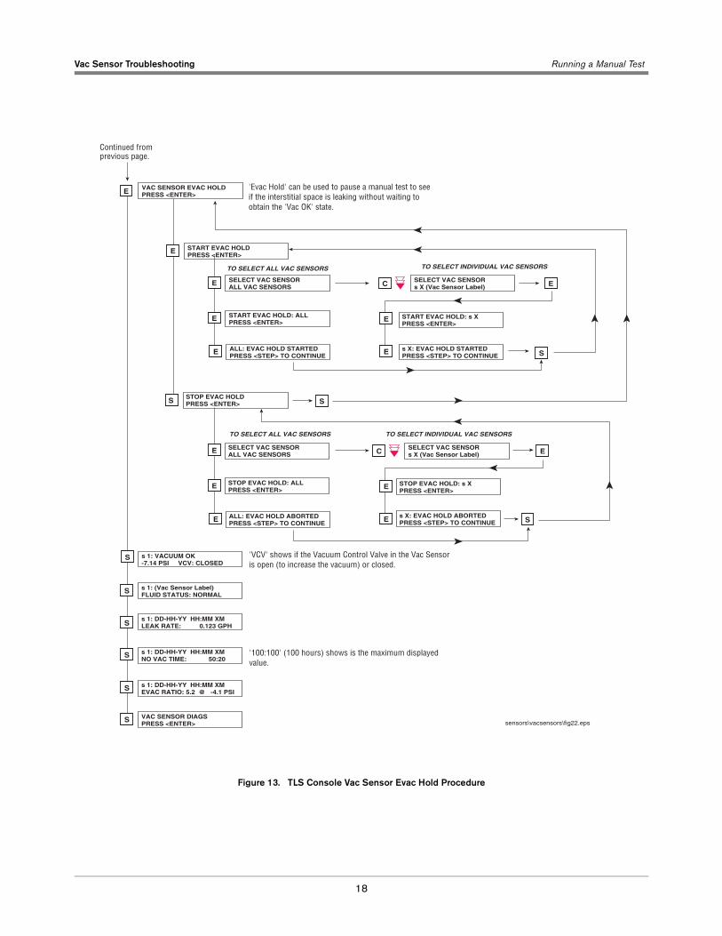
Figure 13. TLS Console Vac Sensor Evac Hold Procedure
s 1: VACUUM OK-7.14 PSI VCV: CLOSED
S
s 1: DD-HH-YY HH:MM XMLEAK RATE: 0.123 GPH
s 1: (Vac Sensor Label)FLUID STATUS: NORMAL
S
S
s 1: DD-HH-YY HH:MM XMNO VAC TIME: 50:20
S
s 1: DD-HH-YY HH:MM XMEVAC RATIO: 5.2 @ -4.1 PSI
S
VAC SENSOR DIAGSPRESS <ENTER>
S
E VAC SENSOR EVAC HOLDPRESS <ENTER>
START EVAC HOLDPRESS <ENTER>
E
SELECT VAC SENSORALL VAC SENSORS
SELECT VAC SENSORs X (Vac Sensor Label)
E
S S
E
START EVAC HOLD: ALLPRESS <ENTER>
START EVAC HOLD: s XPRESS <ENTER>
ALL: EVAC HOLD STARTEDPRESS <STEP> TO CONTINUE
E
E
E
s X: EVAC HOLD STARTEDPRESS <STEP> TO CONTINUE
STOP EVAC HOLDPRESS <ENTER>
E
C
S
TO SELECT INDIVIDUAL VAC SENSORSTO SELECT ALL VAC SENSORS
SELECT VAC SENSORALL VAC SENSORS
SELECT VAC SENSORs X (Vac Sensor Label)
E
E
STOP EVAC HOLD: ALLPRESS <ENTER>
STOP EVAC HOLD: s XPRESS <ENTER>
ALL: EVAC HOLD ABORTEDPRESS <STEP> TO CONTINUE
E
E
E
s X: EVAC HOLD ABORTEDPRESS <STEP> TO CONTINUE
E
C
TO SELECT INDIVIDUAL VAC SENSORSTO SELECT ALL VAC SENSORS
S
sensors\vacsensors\fig22.eps
'Evac Hold' can be used to pause a manual test to seeif the interstitial space is leaking without waiting to obtain the 'Vac OK' state.
'VCV' shows if the Vacuum Control Valve in the Vac Sensoris open (to increase the vacuum) or closed.
Continued fromprevious page.
'100:100' (100 hours) shows is the maximum displayedvalue.

For technical support, sales orother assistance, please visit:
www.veeder.com