Embed Size (px)
Citation preview
1
Air ConditioningAir Conditioning
System TroubleshootingSystem Troubleshooting
2
INTRODUCTION INTRODUCTION
• Troubleshooting air-conditioning equipment involves both the mechanical and electrical systems
• Symptoms may overlap• Mechanical problems may appear to be electrical and vice
versa• Technicians must diagnose problems correctly
• Troubleshooting air-conditioning equipment involves both the mechanical and electrical systems
• Symptoms may overlap• Mechanical problems may appear to be electrical and vice
versa• Technicians must diagnose problems correctly
3
MECHANICAL TROUBLESHOOTING MECHANICAL TROUBLESHOOTING
• Gages and temperature-testing equipment are used when performing mechanical troubleshooting
• Always be aware of the system refrigerant• R-410a pressures are much higher than R-22• R-22 gages on R-410a systems will be over pressurized
and can become damaged• Not all refrigerant oils are compatible, so gages should
be used on only one type of refrigerant
4
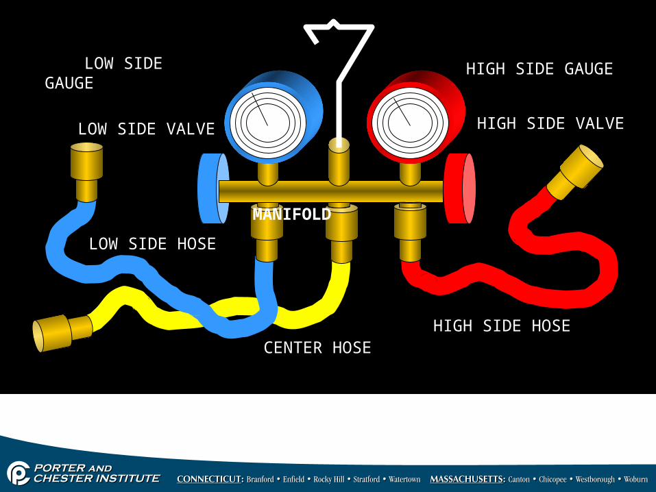
LOW SIDE GAUGE HIGH SIDE GAUGE
LOW SIDE VALVE HIGH SIDE VALVE
LOW SIDE HOSE
HIGH SIDE HOSECENTER HOSE
MANIFOLD
5
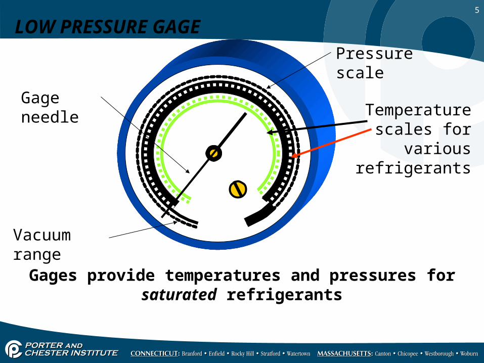
LOW PRESSURE GAGE
Vacuum range
Gage needle
Pressure scale
Temperature scales for various
refrigerants
Gages provide temperatures and pressures for saturated refrigerants
6
GAGE MANIFOLD USAGEGAGE MANIFOLD USAGE• Displays the low- and high-side pressures while the
unit is operating• These pressures can be converted to the saturation
temperatures • Gage manifolds are used whenever the pressures need
to be known for the system • Gages are connected to service ports• Used to calculate superheat and subcooling
• Displays the low- and high-side pressures while the unit is operating
• These pressures can be converted to the saturation temperatures
• Gage manifolds are used whenever the pressures need to be known for the system
• Gages are connected to service ports• Used to calculate superheat and subcooling
7
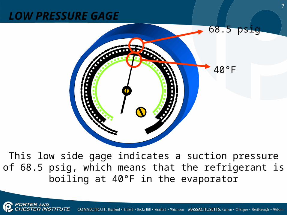
LOW PRESSURE GAGE68.5 psig
40°F
This low side gage indicates a suction pressure of 68.5 psig, which means that the refrigerant is boiling at 40°F in the evaporator
8
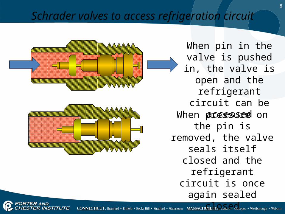
Schrader valves to access refrigeration circuit
When pin in the valve is pushed in, the valve
is open and the refrigerant circuit can
be accessed
When pressure on the pin is removed, the valve seals
itself closed and the refrigerant circuit is once
again sealed closed
9
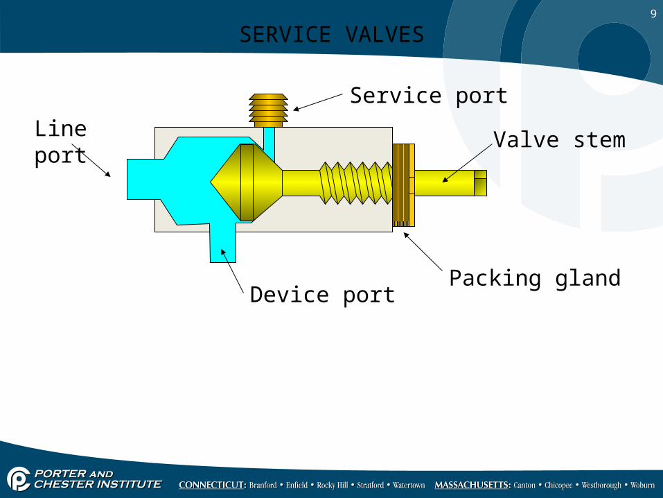
SERVICE VALVES
Service port
Line port
Device portPacking gland
Valve stem
10
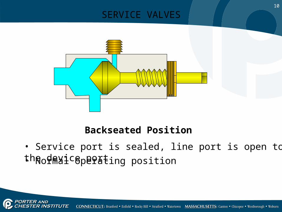
SERVICE VALVES
Backseated Position
• Service port is sealed, line port is open to the device port
• Normal operating position
11
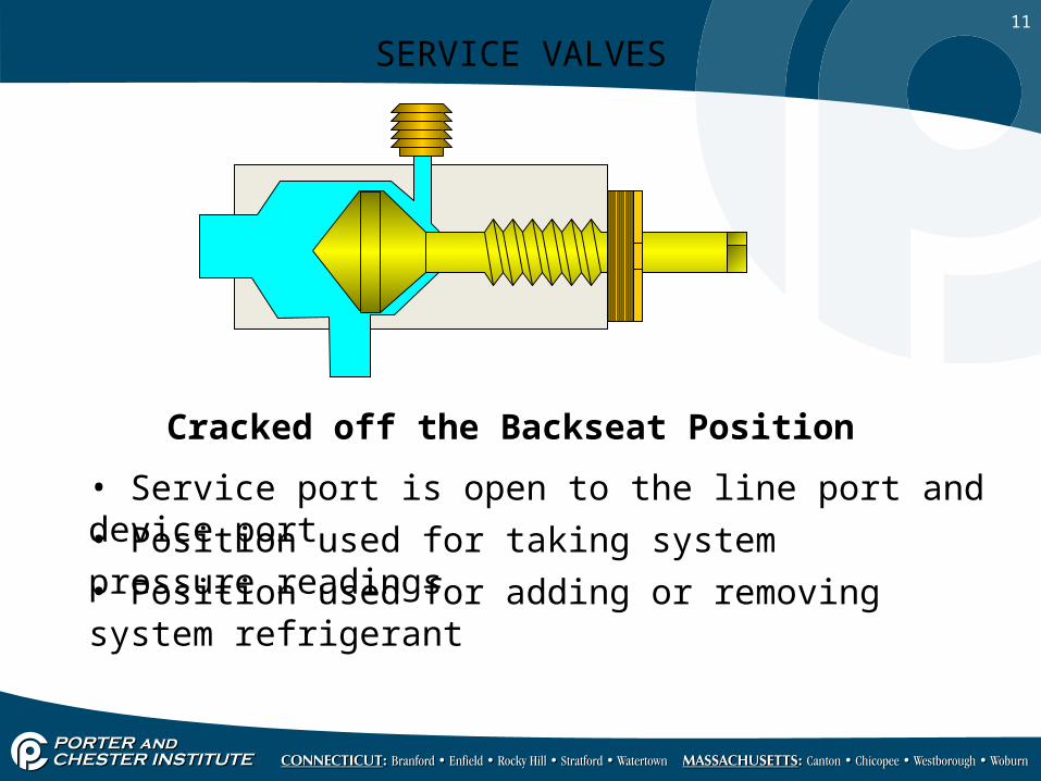
SERVICE VALVES
Cracked off the Backseat Position
• Service port is open to the line port and device port
• Position used for taking system pressure readings
• Position used for adding or removing system refrigerant

12
SERVICE VALVES
Midseated Position
• Service port is open to the line port and device port
• Position used for system evacuation and leak checking
13
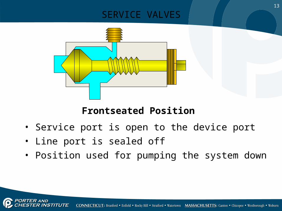
SERVICE VALVES
Frontseated Position
• Service port is open to the device port
• Position used for pumping the system down
• Line port is sealed off
14
WHEN TO CONNECT THE GAGESWHEN TO CONNECT THE GAGES
• Gage manifolds should not be connected every time a system is serviced
• Small amounts of refrigerant escape each time the gages are connected and removed from a sealed system
• Short gage hoses will limit the amount of refrigerant lost• Low-loss fittings should be used
• Gage manifolds should not be connected every time a system is serviced
• Small amounts of refrigerant escape each time the gages are connected and removed from a sealed system
• Short gage hoses will limit the amount of refrigerant lost• Low-loss fittings should be used
15
LOW-SIDE GAGE READINGSLOW-SIDE GAGE READINGS
• Used to compare the actual evaporating pressure to the normal evaporating pressure
• Standard-efficiency systems usually have a refrigerant boiling temperature of about 35°F cooler than the entering air temperature
• Under increased loads, the evaporator is absorbing extra sensible and latent heat from the air
• Gage readings when the system is operating in or close to design range will verify system’s true performance
16
HIGH-SIDE GAGE READINGSHIGH-SIDE GAGE READINGS
• Used to check the relationship of the condensing refrigerant to the ambient air temperature
• Standard efficiency air-cooled condensers condense the refrigerant at no more than 30°F higher than the ambient temperature
• High-efficiency condensers normally condense the refrigerant at a temperature as low as 20°F higher than the ambient temperature
17
TEMPERATURE READINGSTEMPERATURE READINGS• For determination of the system’s superheat and
subcooling temperatures• Common temperatures used for evaluation are:
– Indoor air wet-bulb and dry-bulb temperatures– Outdoor air dry-bulb temperature– Suction-line temperature– Condenser outlet temperature– Compressor discharge line temperature
• For determination of the system’s superheat and subcooling temperatures
• Common temperatures used for evaluation are: – Indoor air wet-bulb and dry-bulb temperatures– Outdoor air dry-bulb temperature– Suction-line temperature– Condenser outlet temperature– Compressor discharge line temperature
18
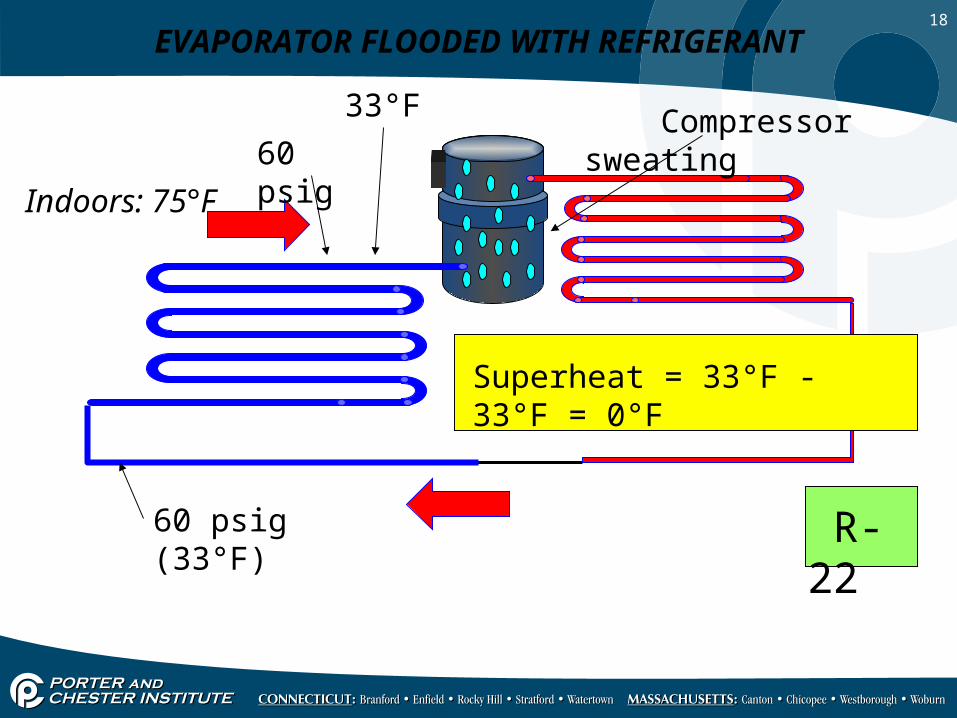
60 psig (33°F)
60 psig
33°F
R-22
EVAPORATOR FLOODED WITH REFRIGERANT
Indoors: 75°F
Superheat = 33°F - 33°F = 0°F
Compressor sweating
19
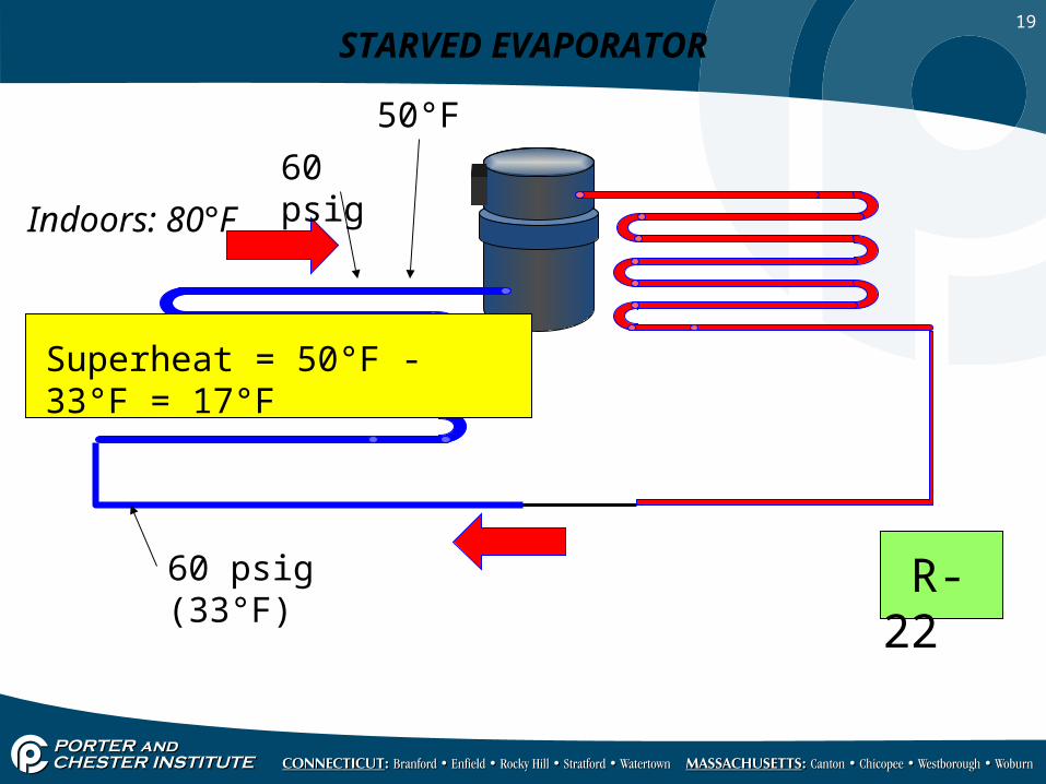
60 psig (33°F)
60 psig
50°F
R-22
STARVED EVAPORATOR
Indoors: 80°F
Superheat = 50°F - 33°F = 17°F

20
41 psig (18°F)
41 psig
70°F
R-22
STARVED EVAPORATOR: Low suction pressure, warm suction line
Indoors: 80°F
Superheat = 70°F - 18°F = 52°F
21
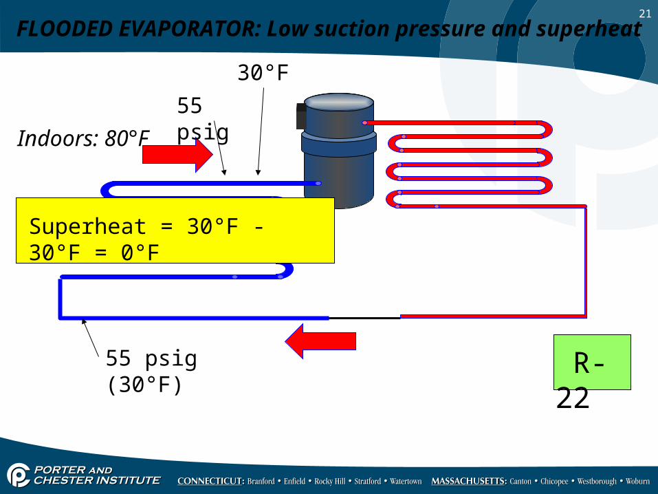
55 psig (30°F)
55 psig
30°F
R-22
FLOODED EVAPORATOR: Low suction pressure and superheat
Indoors: 80°F
Superheat = 30°F - 30°F = 0°F
22
CHARGING SYSTEMS IN THE FIELD CHARGING SYSTEMS IN THE FIELD • When the system is operating correctly under design
conditions, there should be a prescribed amount of refrigerant in the condenser, the evaporator, and the liquid line
• The amount of refrigerant in the evaporator can be measured by superheat
• The amount of refrigerant in the condenser can be measured by subcooling
• When the system is operating correctly under design conditions, there should be a prescribed amount of refrigerant in the condenser, the evaporator, and the liquid line
• The amount of refrigerant in the evaporator can be measured by superheat
• The amount of refrigerant in the condenser can be measured by subcooling
23FIELD CHARGING THE TXV SYSTEM FIELD CHARGING THE TXV SYSTEM
• Reduce the airflow across the condenser to simulate a 95°F outside air temperature
• The superheat check will not work for the TXV because it is designed to maintain a constant superheat of 8° to 12° under any load condition
• A subcooling check of the condenser can be used to check the system charge
• Typical subcooling circuit will subcool the liquid refrigerant from 10° to 20° cooler than the condensing temperature
• Excessive subcooling indicates an overcharge
24
ELECTRICAL TROUBLESHOOTING ELECTRICAL TROUBLESHOOTING
• You need to know what the readings should be to know whether the actual readings are correct or not
• Begin any electrical troubleshooting by verifying that the power supply is energized and that the voltage is correct
• If the power supply voltage is correct, move on to the various components
• You need to know what the readings should be to know whether the actual readings are correct or not
• Begin any electrical troubleshooting by verifying that the power supply is energized and that the voltage is correct
• If the power supply voltage is correct, move on to the various components
25
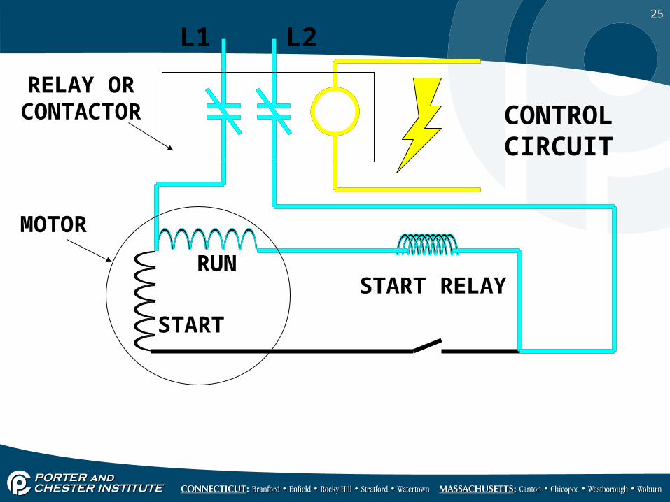
L1 L2
CONTROL CIRCUIT
RELAY OR CONTACTOR
MOTOR
RUN
START
START RELAY
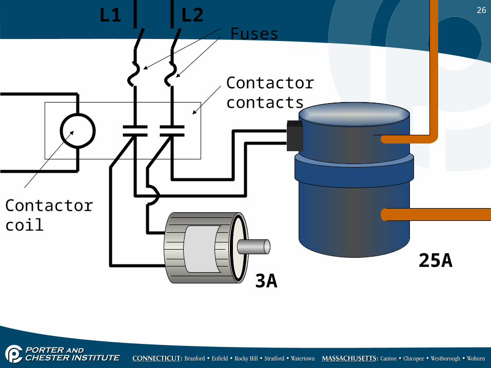
26L1 L2
3A25A
Fuses
Contactor contacts
Contactor coil
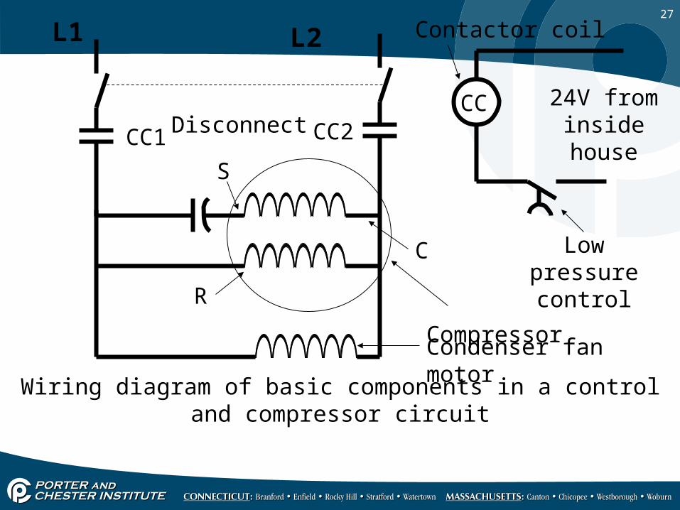
27
L1 L2
Disconnect
CC1 CC2CC 24V from
inside house
Low pressure control
Contactor coil
C
S
R
Wiring diagram of basic components in a control and compressor circuit
Compressor
Condenser fan motor
28
COMPRESSOR ELECTRICAL CHECKUPCOMPRESSOR ELECTRICAL CHECKUP
• Technicians need to be careful when condemning a compressor– Many condemned compressors are not bad– Unnecessary labor and material costs
• Compressor problems can be mechanical or electrical
• Technicians need to be careful when condemning a compressor– Many condemned compressors are not bad– Unnecessary labor and material costs
• Compressor problems can be mechanical or electrical
29
ELECTRICALLY CHECK A SINGLE-PHASE COMPRESSOR ELECTRICALLY CHECK A SINGLE-PHASE COMPRESSOR
• Make certain wires are disconnected from the compressor
• Make certain all compressor terminals are clean• Check resistance from windings to ground (ohmmeter or
megohmmeter)• Check resistance of the start and run windings
• Make certain wires are disconnected from the compressor
• Make certain all compressor terminals are clean• Check resistance from windings to ground (ohmmeter or
megohmmeter)• Check resistance of the start and run windings
30
ELECTRICALLY CHECK A SINGLE-PHASE COMPRESSOR (cont’d.)ELECTRICALLY CHECK A SINGLE-PHASE COMPRESSOR (cont’d.)• Check continuity between run and start terminals• Check voltage between common and run terminals and
between common and start terminals• Voltage readings should be within 10% of the rated
voltage
• Check continuity between run and start terminals• Check voltage between common and run terminals and
between common and start terminals• Voltage readings should be within 10% of the rated
voltage
31
ELECTRICALLY CHECK A THREE-PHASE COMPRESSORELECTRICALLY CHECK A THREE-PHASE COMPRESSOR
• Check resistance from windings to ground• Make certain wires are disconnected from the
compressor• Make certain all compressor terminals are clean • Check each winding from terminal to terminal• The resistance readings should be the same in all
windings
• Check resistance from windings to ground• Make certain wires are disconnected from the
compressor• Make certain all compressor terminals are clean • Check each winding from terminal to terminal• The resistance readings should be the same in all
windings

32
MECHANICALLY CHECKING A COMPRESSOR MECHANICALLY CHECKING A COMPRESSOR
• If the supply voltage is correct, the compressor should start
• If the compressor does not start, the compressor may be stuck
• Reversing the direction of the motor may free the motor
• If the supply voltage is correct, the compressor should start
• If the compressor does not start, the compressor may be stuck
• Reversing the direction of the motor may free the motor
33
COMPRESSOR CAPACITYCOMPRESSOR CAPACITY
• One or more cylinders may not be functioning properly
• Simulate design conditions as closely as possible• If voltage is correct and amperage is very low, the
compressor is not pumping to capacity• Indicated by a high suction pressure and a low head
pressure
• One or more cylinders may not be functioning properly
• Simulate design conditions as closely as possible• If voltage is correct and amperage is very low, the
compressor is not pumping to capacity• Indicated by a high suction pressure and a low head
pressure
34
TROUBLESHOOTING THE CIRCUIT ELECTRICAL PROTECTORS – FUSES AND BREAKERS
TROUBLESHOOTING THE CIRCUIT ELECTRICAL PROTECTORS – FUSES AND BREAKERS
• Open circuit breakers or blown fuses should be treated with caution
• Do not reset or replace a tripped breaker or fuse without trying to determine what caused the fuse to blow or the breaker to trip
• Open circuit breakers or blown fuses should be treated with caution
• Do not reset or replace a tripped breaker or fuse without trying to determine what caused the fuse to blow or the breaker to trip
35
SUMMARY - 1SUMMARY - 1• Troubleshooting air-conditioning equipment involves both
the mechanical and electrical systems• Mechanical problems may appear to be electrical and vice
versa• Gages and temperature-testing equipment are used when
performing mechanical troubleshooting• Gage manifolds are used whenever the pressures need to
be known for the system• Gages are used to calculate superheat and subcooling
• Troubleshooting air-conditioning equipment involves both the mechanical and electrical systems
• Mechanical problems may appear to be electrical and vice versa
• Gages and temperature-testing equipment are used when performing mechanical troubleshooting
• Gage manifolds are used whenever the pressures need to be known for the system
• Gages are used to calculate superheat and subcooling
36
SUMMARY - 2SUMMARY - 2• Gage manifolds should not be connected every time a
system is serviced• Short gage hoses will limit refrigerant loss• Standard-efficiency systems usually have a refrigerant
boiling temperature of about 35°F cooler than the entering air temperature
• Standard efficiency air-cooled condensers condense the refrigerant at no more than 30°F higher than the ambient temperature
• Gage manifolds should not be connected every time a system is serviced
• Short gage hoses will limit refrigerant loss• Standard-efficiency systems usually have a refrigerant
boiling temperature of about 35°F cooler than the entering air temperature
• Standard efficiency air-cooled condensers condense the refrigerant at no more than 30°F higher than the ambient temperature
37
SUMMARY - 3SUMMARY - 3• Temperature readings are needed to calculate
evaporator superheat and condenser subcooling• The amount of refrigerant in the evaporator can be
measured by superheat• The amount of refrigerant in the condenser can be
measured by subcooling• Typical subcooling circuit will subcool the liquid
refrigerant from 10° to 20° cooler than the condensing temperature
• Temperature readings are needed to calculate evaporator superheat and condenser subcooling
• The amount of refrigerant in the evaporator can be measured by superheat
• The amount of refrigerant in the condenser can be measured by subcooling
• Typical subcooling circuit will subcool the liquid refrigerant from 10° to 20° cooler than the condensing temperature
38
SUMMARY - 4SUMMARY - 4• Begin any electrical troubleshooting by verifying that
the power supply is energized and that the voltage is correct
• Use an ohmmeter to check compressor windings for grounds, shorts and open circuits
• Compressor voltage readings should be within 10% of the rated voltage
• If the supply voltage to the compressor is correct, the compressor should start
• Begin any electrical troubleshooting by verifying that the power supply is energized and that the voltage is correct
• Use an ohmmeter to check compressor windings for grounds, shorts and open circuits
• Compressor voltage readings should be within 10% of the rated voltage
• If the supply voltage to the compressor is correct, the compressor should start

39


![Compressor Troubleshooting Guide - RPC · PDF file[Type text] REFRIGERATION & AIR CONDITIONING GUIDE COMPRESSOR TROUBLESHOOTING GUIDE: Understanding the Cooling Cycle 4/17/2009 A1](https://img.pdfslide.us/doc/110x75/5a710e717f8b9a9d538c8dc0/compressor-troubleshooting-guide-rpc-tubeswwwrpctubescomimagescompressortroubleshootingguidepdfpdf.jpg)