Embed Size (px)
Citation preview

TRIZ POWER TOOLS Job # 3 Designing & Prototyping
Building a System by Designing and
Prototyping Subsystems
Jan 2015 Edition

ii
TRIZ Power Tools
Job #3 Designing and Prototyping
January 2015 Edition
ISBN Not applied for
TRIZ Power Tools by Collaborative Coauthors
49 Pages
Copyright 2015 by Collaborative Authors, All rights reserved
iii
Acknowledgements
This book is the work of a collaborative group of coauthors.
Coauthors
Larry Ball
David Troness
Kartik Ariyur
Larry Miller
Badari Kotejoshyer
Don Rossi
Krishnamurthy Vaidyanathan
Petr Krupansky
Editors
Paul Dwyer
Erika Ball
Larry Ball
David Troness
S. Robert Lang
Illustrators
Larry Ball
David Troness
Other Authors, Theoreticians, Practitioners Whose Writings or Teachings have Impacted This
Work
Genrich Altshuller
Ellen Domb
Roni Horowitz
John Terninko
Alla Zusman
Boris Zlotin
Lev Shulyak
Yuri Salamatov
Victor Fey
Eugene Rivin
Darrell Mann
Sergei Ikovenko
Simon Litvin
Peter Ulan
Lane Desborough
Clayton Christensen
Renee Mauborgne
Kim Chan

iv

TRIZ Power Tools
v
The Algorithm
(Table of Contents)
The Algorithm ................................................................................................................................. v
Introduction ..................................................................................................................................... 1
L1-Recall the Segment & Features ................................................................................................. 3
L1-Identify Existing Systems ......................................................................................................... 5
L1 Additively Design and Prototype Sub-Systems ........................................................................ 7
L2-Begin the Function and Requirements Diagram .............................................................. 13
L2-Determine Ideal Subsystem Elements .............................................................................. 13
L2-Iterative Drawing and Problem Solving ........................................................................... 18
L2-Model the Sub-system ...................................................................................................... 19
L2-Create Scaled or Dimensioned Drawings ......................................................................... 20
L2-Prototype the Subsystem and Solve Problems ................................................................. 21
L3-Collect Appropriate Tools ....................................................................................... 24
L3-Stockpile Raw Materials ......................................................................................... 25
L3-Learn How to Use Prototyping Materials ............................................................... 26
L3-Iteratively Prototype ................................................................................................ 26
L2-Document and Witness the Reduction to Practice ........................................................... 28
L2-Update the Function Diagram .......................................................................................... 30
L2-Update the Requirements Diagram .................................................................................. 31
L2-Verify Crucial System Elements ...................................................................................... 33
L2-Iteratively Add Supporting Sub-Systems ......................................................................... 37
L2-If Possible, Consider a Set-Based Approach .................................................................... 37
L1-Simplify the Product or Service .............................................................................................. 38
L1-Investigate Manufacturing Processes and Capabilities ........................................................... 40
L1-File for Patents ........................................................................................................................ 42
L2-Perform a Patent Search ................................................................................................... 43

TRIZ Power Tools
vi
L2-Determine a Patent Strategy ............................................................................................. 43
L2-File Provisional Patents .................................................................................................... 44
L2-File Traditional Patents for a Small Entity ....................................................................... 44
L2-File Traditional Patents for a Large Company ................................................................. 45
L1-Refine the Prototype for Public Feedback (If Necessary) ....................................................... 46
L2-Refine the Aesthetic Form ................................................................................................ 48
L2-Build Refined Prototypes ................................................................................................. 48
L1-Continue Seeking Target Market Feedback ............................................................................ 50

TRIZ Power Tools
Introduction 1
Introduction
(If you are reading the PDF format—navigate the algorithms with the “Bookmarks” to the left. L1,
L2, L3 correspond to levels of the algorithm. The levels are hierarchal; you can go as deeply as
required to resolve your problem. Lower levels (L1, L2) have consolidated methods. If you are
only using the printed text, then use the Table of Contents for the Algorithm)
Prerequisites and Inputs to this book
If you have followed the activities described in TRIZ Power Tools—Job1—Discovering Markets then you
understand the job that your customers are trying to do and you know who the potential job executors are. You also
understand something about what is hindering these customers or blocking them from performing their job. If you
have read Job 2—Choosing Features, then you understand the competitive attributes of the product or service that
you are creating and the attributes of the product or service that are necessary to make the product commercially
viable. Recall that the competitive attributes are the attributes of the product that potential consumers use to
compare their options. When you choose between two cans of soup, what are you looking for? One of the
important attributes is the price. The attributes that determine whether the product or service is commercially viable
is the recurring and non-recurring costs of manufacturing the product; the ability to fit the product within the
allowable business model, etc. In short, we now have the product requirements.
The Output is Prototypes and Manufacturing Knowledge
The output of this book is prototypes that we can show to the customer and protection which will allow us to do so.
Once we have these prototypes, we can circle back to Job 2-Choosing Features and continue the iterative process of
interviewing the market and getting feedback on the prototypes in order to get the features right.
We should again emphasize the point that to truly understand the market and the features that they want, it is
necessary to enter a learning process rather than an execution process. It is unlikely that we will understand the
customer needs the first time around. The consumer generally can tell you when you have it right, but it is our
responsibility to place different concepts before them to help them fully understand their needs.
This problem is equally acute on the business side. It is important to understand the needs of the business and where
they are willing to play in order that the constraint on the market segment does not end up in the business and its
ability to provide and deliver the product or service in the way that the target market segment would like. Thus,
there is the added duty to investigate production methods as part of the prototyping process. When we get back to
the business managers with our prototypes, they will want to understand their recurring and non-recurring costs of
manufacturing. Will they need to purchase new equipment or can the existing equipment be modified?

TRIZ Power Tools
2

TRIZ Power Tools
Recall the Segment and Features 3
L1-Recall the Segment & Features
By this point, we should already know the market segment that we are serving. Market segment equals job + job
executor + constraint on performing the job. If this is not known, then go back and perform this step.
The offering features are not yet set in concrete due to the iterative and learning nature of the innovation process.
We may be in the first iterations, and do not yet understand the features that will fully remove the market and
business constraints. We may still be learning where we are attacking the constraint that the market segment is
saddled with. Should we do this in the product, the service, the manufacturing process, the business model or at
some point in the value chain? We are also still learning the features of the product or service that allow us to
simplify the job for the market segment.
L1 Method
Step 1: Recall the job, the job executor and the constraint on performing the job. This
was originally an output of TRIZ Power Tools—Job #1 Discovering Markets. This was
updated, however, in Job #2 Determining Features.
Step 2: Recall the offering features that will satisfy the target market segment and the
business. This is the main output from Job #2 Determining Features.
Example—Drying Shoes
There is a constant need to wash and dry athletic shoes but this continues to be a difficult
job to perform. Most people will try to get this job done by throwing the shoes into a
clothes dryer. The shoes may not dry entirely during a typical dryer cycle. The shoes
will bang around in the dryer causing noise and may damage the dryer drum or the shoes
themselves. We are not constrained to use a clothes dryer, but we need to get the job of
drying the shoes done. We would like to have a compelling offering for people who want
to perform the job of drying shoes. We would also like to have a compelling offering for
a potential licensee.
Step 1: Recall the job, the job executor and the constraint on performing the job. This
was originally an output of TRIZ Power Tools—Job #1 Discovering Markets. This was
updated, however, in Job #2 Determining Features.
The job is drying washed or wet athletic shoes. The job executor is anyone in a
residential setting. The constraint is drying the shoes quickly and uniformly.
Step 2: Recall the offering features that will satisfy the target market segment and the
business. This is the main output from Job #2 Determining Features.
The features of the offering are the ability to dry the shoes uniformly in 20 minutes with
no damage to equipment or shoes. The offering should cost no more than $5 dollars and
should be simple to buy, install and maintain.

TRIZ Power Tools
4

TRIZ Power Tools
Identify Existing Systems 5
L1-Identify Existing Systems
Whether we use an existing system or not depends a lot on what our goals are and whether we are willing to evolve
existing systems or we are looking for a more ideal system. Sometimes, we just want to see one part of a system
working and it is ok to use ready-made system elements. This is particularly true when existing systems are low-
cost. If we are more interested in identifying much more ideal systems, then the next section will help us to do that.
There we will be looking for the most ideal sub-system elements. Doing this preliminary search won’t hurt anything
though, even if you are looking for the most ideal system.
L1 Method
Step 1: Perform internet and store searches for existing systems that perform all or part
of what you want your system to perform
Example—Drying Shoes
Step 1: Perform internet and store searches for existing systems that perform all or part
of what you want your system to perform
Internet searches for drying shoes shows different approaches to drying shoes.
1—hang the shoes in the dryer by the laces. This can be done by a variety of methods
such as shutting the laces in the dryer door or special suction attachments inside the
dryer.
2—Place the shoes on a dryer rack made specifically for the dryer. (This is a higher cost
solution if the dryer does not come with such a drying rack).
3—Place the shoes inside of a pillow case stuffed with other cloth articles.
4—Use a hair dryer
5—Hang them on a clothes line (slow)
6—Cram a towel into the shoes
7—Stuff shoes with newspaper (slow)

TRIZ Power Tools
6
TRIZ Power Tools
Prototype by Iteratively Designing and Adding Sub-Systems 7
L1 Additively Design and Prototype
Sub-Systems
Set-Based System Creation
If your effort is large enough to consider multiple solution concepts, you may consider several system candidates at
a time. This is sometimes referred to as set-based system development. The effort begins with several candidate
systems which come close to meeting the original target and range requirements. The capabilities of these systems
are communicated upward to the super-system designers. Over time, as the super-system designers see the
capabilities of the various sub-systems, the targets change and the ranges of what is acceptable begin to narrow. All
this time, the candidate systems are evolving toward the targets and ranges given. Finally, the ranges narrow to the
final values and tolerances which the system will use. What has just been described is the process that Toyota uses
to develop its cars. Rather than sending down one rigid set of requirements, targets and ranges are flowed down and
capabilities flow back up.
Note that this all allows for prototype development, but at a larger scale. This may not be possible for small
organizations or individuals.
Also note that the design and prototype process is iterative and based upon discoveries that occur as the system is
being created or evolved. The idea is to reduce the risk of each system while keeping the largest set of potential
solutions for a long as possible.
Iteratively Creating the Product or Service
The process of creating a product or service from scratch is one of iteratively adding functional sub-systems to a
system until the system is complete. This is necessary because of the difficulty of thought in creating large systems.
While humans are advanced, we are not that advanced! Almost all large systems are composed of subsystems that
were designed and built by teams. These subsystems are likewise composed of further subsystems that require a lot
of time to design, prototype and shake the bugs out. It may come as a surprise to many people that this is how large
and complex systems are built. Even less complicated systems are designed and built this way.
Where to Start: The Primary Useful Function
This iterative process begins with the primary useful function. The primary useful function acts on the element of
the super-system (job) that it is meant to serve. This product holds a special place as the system product. Everything
that operates on this product has higher functional rank in the system. Supporting elements which do not serve this
product are generally referred to as auxiliary functions. These have lower rank. As each subsystem is added, the
supporting elements are added further and further from the system product. Supporting elements should be
cautiously added as they are less necessary and drive the cost and complexity of the final offering.
Determining the Ideal Sub-system elements
One way to cautiously add subsystems is to idealize each one before we add it. As we add each subsystem, we must
manage important decisions concerning the purpose of the elements, the physical phenomenon or effect that will
deliver the function and the functional objects that will deliver the physical phenomenon. These decisions are very
important and affect all downstream decisions. Consequently, it is important that we add these elements in the most
ideal way possible. Detailed process steps are given to ensure the proper consideration.

TRIZ Power Tools
8 Prototype by Iteratively Designing and Adding Sub-Systems
Drawing the Architecture (Schematics, etc.)
Once we think that we know the ideal sub-system elements, we are ready to draw a picture which shows the
architecture of these elements. These drawings can be quite crude and do not need to always show scale. They
show, schematically, how everything works together. The first drawings may be done on a napkin, so to speak or
they may be drawn in your invention log or journal. The main thing that you are trying to accomplish is to show the
features of the sub-system elements that will control how well the subsystem works. Also shown is the spatial
relationship of the elements to each other.
When you start to draw the system you will begin to note various problems. It is usually necessary to start solving
these problems at this stage. The book TRIZ Power Tools—Job #5 Resolving problems covers this subject.
This drawing is often iterative. The intent is still to make the added subsystem as ideal as possible in terms of the
use of readily available materials. This is practically accomplished by repeatedly drawing the subsystem, each time
making small improvements. Drawing the subsystem many times can be helpful in reducing the number of elements
and their interfaces. For the final drawings, some people like to draw it as “richly” as possible. This means adding
as much visual detail as you can to help make the idea real.
Modeling the Subsystem
The need for modeling is largely dependent on getting the physics right or close on the first rounds. Often, the size
of the effects and the sizing of the components will determine the next level of drawing or the layout. The outcome
of the modeling can also effect the basic schematic that we have just made if the sizes of the elements are much
different than we originally expected.
Models are usually created from a functional drawing of what is going on such as a timing diagram or a free-body
diagram. Beginning models should be as simple as possible to give a rough-order-of-magnitude of the sizing. The
need for more detail will become evident on further iterations of the prototype.
It is realized that many people do not have the background to model the physics. If this is the case, then this step
may be skipped in favor of jumping to the prototype, but the risks of spending a lot of time on prototyping grows
substantially. An example of an inventor that avoided modeling was Thomas Edison. Nichole Tesla worked with
Edison for a time and noted that Edison’s operation would be greatly improved by employing a little physics. Tesla
was a noted physicist in his day and had little tolerance for cutting and trying. Edison, on the other hand, was well
noted for his large-scale invention factory where people were employed to cut and try.
Crude Dimensioned Drawings
This is another step that can be helpful, or it can get in the way of crude prototypes. (On the first rounds you may
want to skip this step in order to create very crude prototypes. Sometimes just slapping together a bunch of stuff is
all you really need to do). However, in order to preserve materials, it is often helpful to draw, at least, a hand
drawing using dimensions in order to purchase the right amount of materials and to make sure that everything fits
together properly. The skill to know when to draw detailed drawings will come with experience.

TRIZ Power Tools
Prototype by Iteratively Designing and Adding Sub-Systems 9
Building the prototype by iteratively solving problems
Building and testing functional prototypes helps us to see the physics and think deeply about what is happening.
IDEO1 refers to this as “Build to Think and Think to Build”. This is where the greatest learning occurs because we
get to see how various parameters of the objects control the functions that we are trying to deliver. It also is where
we may discover difficult problems such as harmful functions and contradictions. These problems should be
handled at this step. TRIZ Power Tools—Job #5 Resolving Problems helps us to overcome these problems in a
systematic way. This is an iterative process that can take some effort and time for each subsystem.
Many product developers get caught up in this step and spend too much time and resources here. IDEO will be the
first to tell you that starting crude and simple is the best way to go. One can learn a lot from simple prototypes. The
purpose and audience of prototypes is discussed further. Remember that the prototype should be matched to the
audience and the product developer is the most important audience to begin with. You need to be convinced that
your idea is worth its salt before you have the courage to continue.
Humans have the innate ability to think with their hands. There is no substitute for making stuff yourself. The
physical act of creation teaches us in so many ways. This is where intuition comes from, practical experience. The
more senses that get involved, the more that we will know when we are finished. This type of knowledge cannot be
learned from textbooks and is often not valued in the educational world. When we act and experience, our brains
record thousands of pieces of “tacit knowledge”. The skilled craftsman is filled with such knowledge and so is the
people that build their own prototypes, no matter how crude. Salvaging pieces of equipment from other devices and
using them again only increase our tacit knowledge. While these books are trying to help us to understand other
intellectual tools for inventing, we also need to increase the skills and experience necessary for intuitive inventing.
This step can have interesting effects on the emotions and intellect of the innovator as we see how our hypothesis
works out. Sometimes discouragement sets in and we need to take a short break to think through what we are doing.
This is fine so long as we do not let the discouragement stop us.
Documenting the Idea and Witnessing the Reduction to Practice
Once we have proven to ourselves that our idea is workable, we may want to document the idea and witness the
reduction to practice. In some countries, where “first to patent” is the rule then time may be of essence and a patent
should be filed. In the United States, the first to witness the reduction to practice has the upper-hand and you may
want to wait until you have added all of the sub-system elements to file.
Continuing to Iteratively Add Sub-systems
Each function that we add may need supporting sub-systems. We can add these in a systematic way using a function
diagram and/or a requirements diagram. A requirements diagram helps us to graphically show the next level of
decomposition or derivation of requirements. On each round of iteration, we note the parameter values that are
required to perform the necessary functions. These parameter levels may be built-in or functions may be required to
deliver them. Let’s say that we have identified a function that requires the heating of object in order to allow a
chemical reaction to progress. The next level of requirements would stipulate a temperature that must be achieved
and a function that is required to heat the element to the required level. Thus, the new subsystem must be added.
1 IDEO is a premier company that designs products and services for other companies. You may think of them as a hired gun with tremendous
capabilities and resources. They are particularly famous for their design process often referred to as “Design Thinking”. The steps of this
process are included in the TRIZ Power Tools book suite.
TRIZ Power Tools
10 Prototype by Iteratively Designing and Adding Sub-Systems
L1 Method
Step 1: Identify the primary useful function that the system performs. What does it
operate on and how does it modify or control it?
Step 2: Identify potential physical phenomenon to deliver the chosen function. If this is
the first iteration, the function should be the primary useful function identified in the last
step.
Step 3: Look for existing or available resources that could be used to deliver the physical
phenomenon. If possible, these resources should already exist in the environment or
already be a part of the job that needs to be done. Sometimes they are commercially
available products that can be modified to do what you would like.
Step 4: With these objects in mind, draw an architecture that can deliver the physical
phenomenon. The drawings do not need to be to scale, but should show the controlling
features.
Step 5: If possible, model the sub-system. Determine the parameter values necessary to
control the function to the chosen level.
Step 6: Make scale drawings or diagrams of what you are about to build.
Step 7: Make prototypes using readily available materials or existing components or
subsystems. Consider modifying existing and inexpensive materials or even discarded or
second hand items. Iteratively build and test different design features to give the control
that you need. Loop back to previous steps as needed. Resolve any resulting problems
with the subsystem before progressing.
Step 8: If cycle times are long for adding sub-systems then consider documenting and
witnessing your concepts.
Step 9: Continue to iteratively add supporting subsystems by determining the supporting
functions needed and jumping back to step 1 to add the next subsystem.
Step 10: If possible, consider other existing and non-existing systems. Continue the
refining or evolution of these systems. Narrow down the prospects to meet the super-
system requirements.
L1 Example—Drying Shoes
Step 1: Identify the primary useful function that the system performs. What does it
operate on and how does it modify or control it?
The primary useful function is to move moisture.
Step 2: Identify potential physical phenomenon to deliver the chosen function. If this is
the first iteration, the function should be the primary useful function identified in the last
step.
Potential physical phenomena are: Evaporation, centrifugal force, capillary action,
desiccation, rapid change of pressure (evaporation), vibration (potentially ultra-sound)
Step 3: Look for existing or available resources that could be used to deliver the physical
phenomenon. If possible, these resources should already exist in the environment or

TRIZ Power Tools
Prototype by Iteratively Designing and Adding Sub-Systems 11
already be a part of the job that needs to be done. Sometimes they are commercially
available products that can be modified to do what you would like. Choose one of the
resources to deliver the phenomenon.
Following are potential resources that could be used to deliver the physical phenomena:
---Evaporation: Use of the sun. The sun is not reliable in certain locations.
---Evaporation: Simply setting the shoes out in a warm room. The evaporation rate is
normally quite low and would need to be boosted if drying time is important.
---Evaporation: A clothes dryer could be used. Shoes bounce around in a dryer thus
making a lot of noise. They may damage the dryer or other clothes.
---Evaporation: A food oven could be used. Cultural biases may need to be overcome.
---Evaporation: A microwave oven could be used. People might be concerned that
something strange might happen due to various shoe materials.
---Centrifugal Force: The washer spin cycle has high centrifugal force, but the shoes are
rarely well positioned to take advantage of it.
---Movement by gravity: Gravity will move liquid water through a fabric up to a point
but not enough to dry.
---Movement of gasses: The clothes dryer moves air about, but the velocity of the air is
low.
---Vacuum: A vacuum cleaner can create a slight vacuum but not sufficient to dry
clothes.
---Surface Tension: The surface tension of the fabric in the shoe draws the water from
areas that are more abundant to areas that are less abundant. Other dry fabrics such as old
towels can be used to dry off liquid, but their effectiveness is low.
---Desiccation: The water must first evaporate from the shoes in order to arrive at the
desiccant. The desiccant is mostly a storage medium.
Finally, the physical phenomenon is chosen: The clothes dryer is chosen since it is a
natural extension of drying the clothes and the washer was already most likely used to
wash the clothes.
Step 4: With these objects in mind, draw an architecture that can deliver the physical
phenomenon. The drawings do not need to be to scale, but should show the controlling
features. On the first iteration, the drawings are simple but should probably be noted in
3 1 The shoes are
somehow dried
with the clothes
dryer

TRIZ Power Tools
12 Prototype by Iteratively Designing and Adding Sub-Systems
the invention journal. This establishes the idea and the date that it was created. In this
case, the drawings are witnessed because the idea may be significant.
Step 5: If possible, model the sub-system. Determine the parameter values necessary to
control the function to the chosen level.
This step is not necessary due to the simplicity of the idea. What is needed is a very
simple prototype
Step 6: Make scale drawings or diagrams of what you are about to build.
Scale drawings are not needed. Instead, a simple prototype is required.
Step 7: Make prototypes using readily available materials or existing components or
subsystems. Consider modifying existing and inexpensive materials or even discarded or
second hand items. Iteratively build and test different design features to give the control
that you need. Loop back to previous steps as needed. Resolve any resulting problems
with the subsystem before progressing.
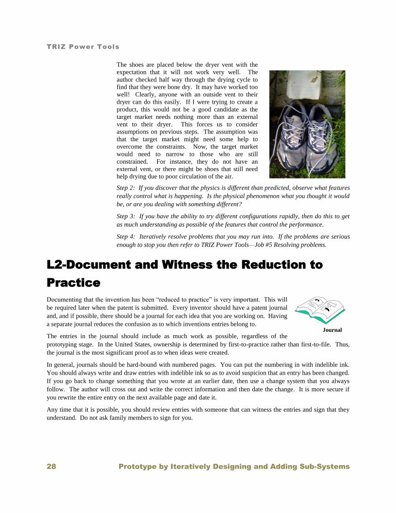
The shoes are placed below the dryer vent with the
expectation that it will not work very well. The author
checked half way through the drying cycle to find that
they were bone dry. It may have worked too well!
Clearly, anyone with an outside vent to their dryer can do
this easily. If I were trying to create a product, this
would not be a good candidate as the target market needs
nothing more than an external vent to their dryer. This
forces us to consider assumptions on previous steps. The
assumption was that the target market might need some
help to overcome the constraints. Now, the target market
would need to narrow to those who are still constrained.
For instance, they do not have an external vent, or there
might be shoes that still need help drying due to poor
circulation of the air.
Step 8: If cycle times are long for adding sub-systems then consider documenting and
witnessing your concepts.
Step 9: Continue to iteratively add supporting subsystems by determining the supporting
functions needed and jumping back to step 1 to add the next subsystem.
Dryer Vent
TRIZ Power Tools
Prototype by Iteratively Designing and Adding Sub-Systems 13
L2-Begin the Function and Requirements
Diagram
The creation of a system always begins with the main useful function of the system. This is the function that we
have chosen to provide that will help perform the job for the target market segment. In the book, TRIZ Power
Tools—Job #2 Deciding Features, we decided the requirements for the part of the value chain that we are working
on. Depending on where we are attacking the constraints on the target market, we could be working on the product,
service, manufacturing process, business model or the delivery channels. We are designing and prototyping that part
of the system where we have decided to remove the constraints.
The process of creating a product or service from scratch is one of iteratively adding functional sub-systems to a
system. This iterative process begins with the primary useful function of the system and knowledge of how well this
function has to be achieved.
L2 Method
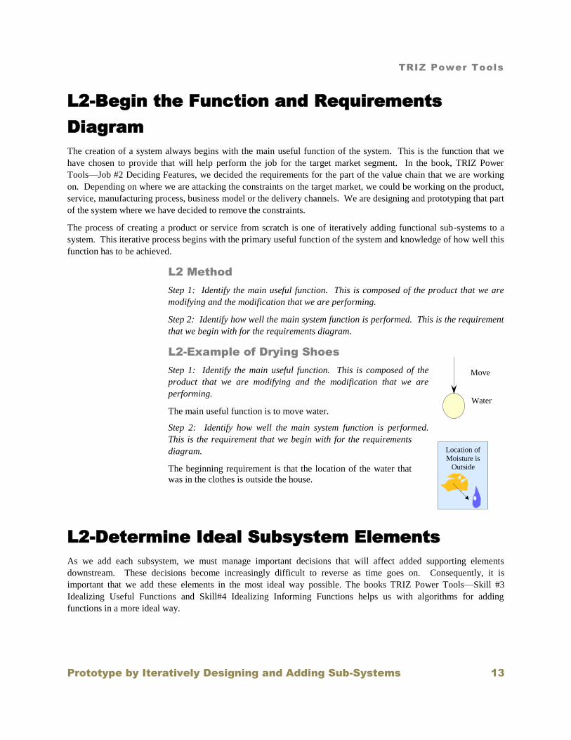
Step 1: Identify the main useful function. This is composed of the product that we are
modifying and the modification that we are performing.
Step 2: Identify how well the main system function is performed. This is the requirement
that we begin with for the requirements diagram.
L2-Example of Drying Shoes
Step 1: Identify the main useful function. This is composed of the
product that we are modifying and the modification that we are
performing.
The main useful function is to move water.
Step 2: Identify how well the main system function is performed.
This is the requirement that we begin with for the requirements
diagram.
The beginning requirement is that the location of the water that
was in the clothes is outside the house.
L2-Determine Ideal Subsystem Elements
As we add each subsystem, we must manage important decisions that will affect added supporting elements
downstream. These decisions become increasingly difficult to reverse as time goes on. Consequently, it is
important that we add these elements in the most ideal way possible. The books TRIZ Power Tools—Skill #3
Idealizing Useful Functions and Skill#4 Idealizing Informing Functions helps us with algorithms for adding
functions in a more ideal way.
Water
Move
Location of
Moisture is Outside

TRIZ Power Tools
14 Prototype by Iteratively Designing and Adding Sub-Systems
In order to make the necessary design decisions, we do not take this function for granted. We probe to see if there is
something more ideal. Is this the real product that we want to modify? Is this the real modification that we want to
perform on the product?
Idealizing Each Added Useful Function
The first step to idealizing a useful function is to identify and isolate the final ideal state in functional terms. We
start by considering useful functions first, because informing functions are actually a special case of useful functions
and one major path of idealizing harmful functions is to turn them into useful functions. Once they are turned into
useful functions, they may be idealized using the steps shown in this chapter.
As we add each subsystem, we must manage important decisions that will affect added supporting elements
downstream. These decisions become increasingly difficult to reverse as time goes on. Each new function that is
added requires the same process as the primary useful function. Since this is the first and most important function
that is required in the system, let’s see how the process works for the primary useful function.
The first decision that we must make is whether we really want to serve the given system product or consider a more
ideal product. What could be more ideal? For instance, if we need to serve multiple elements, we ask if we can act
upon the natural grouping or a multiplicity of the products at one time. If the product could be slightly modified,
then there might be no need to modify it at all. If the product is a waste element then performing an upstream
function in a way that does not produce the waste element may be more ideal.
Once we have determined what product we really want to serve we ask whether the modification that we have
initially chosen is the one we want to continue with. Perhaps it may be more ideal to perform the inverse
modification where modifications that are relative to something are not performed, but the relative object is
modified instead. Perhaps a more ideal modification would be stated differently. It might be in a different sequence
than normally performed or done in such a way as to reduce the energy consumption.
Once we have established product and modification, then we need to identify potential physical phenomenon that
will be used to deliver the function. We usually have several to choose from.
Before we make a final choice of physical phenomenon to deliver the modification, we identify the resources at our
disposal. What systems are readily available? What have we used in the past? What elements in the system could be
pressed into service? What inexpensive substances exist in the system or in the environment? Now we are ready to
identify various physical phenomenon that will be used to deliver the function. We usually find that the potential
phenomena are not unique and we may have several to choose from.
Next, we look around to decide what objects we have readily available to deliver the chosen physical phenomena.
The decision of which of the potential physical phenomena to use is highly influenced by the available resources in
the system. This is because we would like to introduce no new physical objects or substances into the system if
possible.
Following the choice of the objects to deliver the physical phenomenon, we need to decide what the architecture of
the system is. This means that we identify the attributes of the objects that have the most influence on how well the
function is performed and we determine the level that these attributes must have. These attributes and their
attending levels establish the architecture of the system. Depending on the complexity of the system, there are a
variety of tools that can help us to decide the levels that the object attributes need to assume. Sometimes, we can
use models if the physics is well understood. Other times, we may need to create simple prototypes to perform
experiments.

TRIZ Power Tools
Prototype by Iteratively Designing and Adding Sub-Systems 15
L2-Method
Step 1: If all you have is the main useful function then start with this. If the main useful
function is an informing function then start with this.
Step 2: If the function that you are adding is a useful function then go to TRIZ Power
Tools—Skill #3 Idealizing Useful functions and use the approaches there to Idealize the
function that you are adding.
Step 3: If the added function is an informing function then go to TRIZ Power tools—
Skill#4 Idealizing Informing Functions and follow the algorithm at the required level.
Step 4: As problems arise, use the methods of TRIZ Power Tools—Job #5 Resolving
Problems to resolve these problems.
Example—Drying Shoes
Step 1: If all you have is the main useful function then start with this. If the main useful
function is an informing function then start with this.
On the first iteration, we are starting with the main useful function having to do with
drying the shoes.
Step 2: If the function that you are adding is a useful function then go to TRIZ Power
Tools—Skill #3 Idealizing Useful functions and use the approaches there to idealize the
function that you are adding.
To illustrate this step, let us consider the drying of fabric
shoes that become moist during washing or by accident if
the water is clean enough. The market, then, is people who
are trying to rapidly dry their shoes following a wash or
accident.
The ideal product is the water and the ideal modification is to move the
water. The shoes are not the product since we do not want the shoes to be
modified in any way. The moisture may have modified the shoes more than
we would like, but that is a separate issue. All that we want to do is to
change the location of the moisture from being inside the shoes to being
elsewhere.
Potential Physical Phenomena that could move water are:
---Evaporation
---Centrifugal force
---Movement by Gravity
---Movement of gasses
---Vacuum
---Surface Tension
---Desiccation.
Following are potential resources that could be used to deliver the physical phenomena:
---Evaporation: Use of the sun. The sun is not reliable in certain locations.
Water
Move

TRIZ Power Tools
16 Prototype by Iteratively Designing and Adding Sub-Systems
---Evaporation: Simply setting the shoes out in a warm room. The evaporation rate is
normally quite low and would need to be boosted if drying time is important.
---Evaporation: A clothes dryer could be used. Shoes bounce around in a dryer thus
making a lot of noise. They may damage the dryer or other clothes.
---Evaporation: A food oven could be used. Cultural biases may need to be overcome.
---Evaporation: A microwave oven could be used. People might be concerned that
something strange might happen due to various shoe materials.
---Centrifugal Force: The washer spin cycle has high centrifugal force, but the shoes are
rarely well positioned to take advantage of it.
---Movement by gravity: Gravity will move liquid water through a fabric up to a point
but not enough to dry.
---Movement of gasses: The clothes dryer moves air about, but the velocity of the air is
low.
---Vacuum: A vacuum cleaner can create a flow of air through the fabric. This is an
interesting possibility since clothes dryers are not really good at drawing air through
fabric.
---Surface Tension: The surface tension of the fabric in the shoe draws the water from
areas that are more abundant to areas that are less abundant. Other dry fabrics such as old
towels can be used to dry off liquid, but their effectiveness is low.
---Desiccation: The water must first evaporate from the shoes in order to arrive at the
desiccant. The desiccant is mostly a storage medium.
Finally, the physical phenomenon is chosen: The clothes dryer is chosen since it is a
natural extension of drying the clothes and the washer was already most likely used to
wash the clothes.
Step 3: If the added function is an informing function then go to TRIZ Power tools—
Skill#4 Idealizing Informing Functions and follow the algorithm at the required level.
We are not working with an informing function.
Step 4: As problems arise, use the methods of TRIZ Power Tools—Job #5 Resolving
Problems to resolve these problems.
3 1 The shoes are
somehow dried
with the clothes
dryer

TRIZ Power Tools
Prototype by Iteratively Designing and Adding Sub-Systems 17
Just throwing the shoes into the dryer is problematic. They bounce around making a lot
of noise and can damage the dryer or the clothes, if there are any. From TRIZ Power
Tools—Skill #5 Solving Problems, we create a function diagram of the problem.
Note that everything in our system is red. The green and yellow are super-system
elements. The yellow is the system product, the object that our system modifies.
The next step is to do a causal
analysis of the problem and discover
the deeper problem. In this case we
will use a simplified approach and
identify the harmful functions as the
problem. We note that there are two
problematic functions dealing with
the shoes. The shoes damage the
drum and the clothes.
Water
Heater
Shoe Air Heats
Fan Moves
Clothes
Drum
Damages Damages Heats
Moves
Heats Moves
Moves
Vaporizes
Heats
Moves
Heats
Moves
Shoe
Clothes
Drum
Damages Damages
TRIZ Power Tools
18 Prototype by Iteratively Designing and Adding Sub-Systems
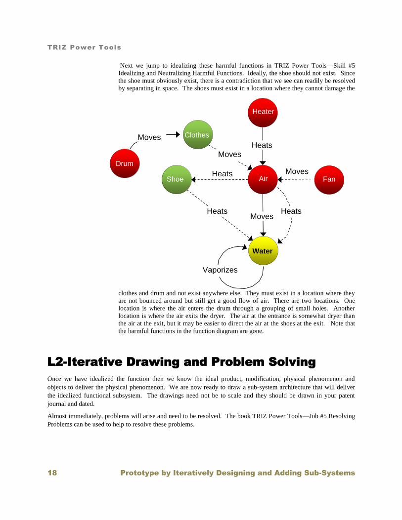
Next we jump to idealizing these harmful functions in TRIZ Power Tools—Skill #5
Idealizing and Neutralizing Harmful Functions. Ideally, the shoe should not exist. Since
the shoe must obviously exist, there is a contradiction that we see can readily be resolved
by separating in space. The shoes must exist in a location where they cannot damage the
clothes and drum and not exist anywhere else. They must exist in a location where they
are not bounced around but still get a good flow of air. There are two locations. One
location is where the air enters the drum through a grouping of small holes. Another
location is where the air exits the dryer. The air at the entrance is somewhat dryer than
the air at the exit, but it may be easier to direct the air at the shoes at the exit. Note that
the harmful functions in the function diagram are gone.
L2-Iterative Drawing and Problem Solving
Once we have idealized the function then we know the ideal product, modification, physical phenomenon and
objects to deliver the physical phenomenon. We are now ready to draw a sub-system architecture that will deliver
the idealized functional subsystem. The drawings need not be to scale and they should be drawn in your patent
journal and dated.
Almost immediately, problems will arise and need to be resolved. The book TRIZ Power Tools—Job #5 Resolving
Problems can be used to help to resolve these problems.
Water
Heater
Shoe Air Heats
Fan Moves
Clothes
Drum
Heats Moves
Heats Moves
Vaporizes
Heats
Moves

TRIZ Power Tools
Prototype by Iteratively Designing and Adding Sub-Systems 19
Method
Step 1: Draw a Baseline system that represents the situation in your invention journal.
Be as specific as possible. (The system may already exist but in flawed form.) If you are
not changing the system, then the existing system will serve as the baseline system.
Redrawing multiple times will help to get the architecture right. You may want to witness
the drawings.
Step 2: As problems arise, use the methods of TRIZ Power Tools—Job #5 Resolving
Problems to resolve these problems.
Example—Drying Shoes
Step 1: Draw a Baseline system that represents the situation in your invention journal.
Be as specific as possible. (The system may already exist but in highly flawed form.) If
you are not changing the system, then the existing system will serve as the baseline
system. Redrawing multiple times will help to get the architecture right. You may want
to witness the drawings.
On the first iteration, the drawings are simple but should probably be noted in the
invention journal. This establishes the idea and the date that it was created. In this case,
the drawings are witnessed because the idea may be significant.
Step 2: As problems arise, use the methods of TRIZ Power Tools—Job #5 Resolving
Problems to resolve these problems.
At this point, we can anticipate problems, but it is better to prototype and see if these
problems really exist.
L2-Model the Sub-system
Sometimes, cutting and trying is just too slow. Even simple models of the sub-system can save a lot of time,
especially if there is a lot of physics involved. Models can help you to set the levels of the controlling features
which, in turn, helps to visualize the final system. If the physics are not well known then it may be good to
hypothesize the physics and then build a model using the hypothesis as a guide. As a matter of practicality, the
author has often found that many conceptual models can be built by going back to “first principles” such as
conservation principles, continuity, etc.
Dryer Vent

TRIZ Power Tools
20 Prototype by Iteratively Designing and Adding Sub-Systems
Sometimes, rapid prototyping is much faster than modeling so this step can be skipped. This is often true in cases
where setting up and running models can be very time consuming such as computational fluid dynamics models. On
the other hand, be open to advances in areas that have been difficult to model.
Method
If possible, model the subsystem. Use the model to set parameter values. Consider using
TRIZ Power Tools—Skill #8 Identifying and Mobilizing Function Resources to identify
clever means to mobilize these resources.
Example—Cleaning Shoes
If possible, model the subsystem. Use the model to set parameter values. Consider
using TRIZ Power Tools—Skill #8 Identifying and Mobilizing Function Resources to
identify clever means to mobilize these resources.
On the first round, we are jumping directly to the prototype and don’t need to do this.
L2-Create Scaled or Dimensioned Drawings
Now that you know the levels of the parameters, it is possible to make scale models or drawings of the subsystem.
These drawings will greatly help you to see how things fit together and potential problems that can arise. They will
also give ideas as to how the sub-system objects can more conveniently fit together. Most of the time, it is not
necessary to make a highly detailed drawing which follows drawing standards. If you are working with a modeling
shop, it is usually sufficient to create a very simply dimensioned drawing. You should probably only be using a
modeling shop if you are on later rounds of prototyping. In the early stages, it is often overkill. Building your own
prototype in a garage is usually faster and gives more rounds of learning than having someone build it for you.
Method
If possible, create scale models or drawings of the subsystem. It may be necessary to do
this several times in order to create a simple architecture.
Example—Cleaning Shoes
If possible, create scale models or drawings of the subsystem. It may be necessary to do
this several times in order to create a simple architecture.
On the first round, we are jumping directly to a simple prototype and don’t need to create
scale drawings.

TRIZ Power Tools
Prototype by Iteratively Designing and Adding Sub-Systems 21
L2-Prototype the Subsystem and Solve
Problems
The Value of Prototyping
Building prototypes increase our “tacit knowledge” of how and why things work. It increases our personal data
banks for future projects. Truly, we think with our hands2 when we create prototypes. Even though these books are
to help us move forward intellectually, there is an element of inventing that cannot be replaced with technical
knowledge and that comes from building and taking apart stuff. Working with others that have this tacit, practical
knowledge can save a lot of time, especially when it comes to discovering how to manufacture your ideas.
Following is a great example of the spirit of prototyping by Patrick Hale and was given at the Mark Niver memorial
My name is Patrick Hale . . . and I want to share a story with you about a very unique friend of mine, who was
known for giving and sharing in the most unusual of ways. Let me take you back in time . . . a time when Jimmy
Carter was in the White House. I started drag racing about the same time Mark Niver did. I made my very first pass
at Beeline drag way in 1970 during my freshman year at ASU. A few years later, in 1978, I bought my very first
dragster from Mike Abby, who along with John Powers, are our hosts here tonight. Thank you guys for this tribute
to Mark Niver.
At the time I was a young engineer, fresh out of college, working at AiResearch. I had also started working on a
computer program that could predict the ET and MPH for all kinds of drag racing cars. This computer simulation
worked really well for my own dragster and a few other racers knew about it at the time.
At the end of 1979, another AiResearch engineer tracked me down and asked if I could do a computer simulation for
a Pro Comp dragster. He had an idea for some new kind of supercharger and wanted to know how much quicker and
faster a dragster would be if the standard 14-71 blower was replaced with a “Lysholm compressor”. That engineer
was Norm Drazy. I told Norm . . . yes, I could do that. But I would need to know some things about a Pro Comp
dragster, like how much it weighed and how much HP it made. As we got more and more into the computer
simulation the aero differences between my small block Chevy dragster and a big-tired, big-winged, Hemi-powered
Pro Comp dragster needed to be understood. This was early 1980, there wasn’t any wind tunnel data for dragsters,
and my experience with Lear jets just didn’t apply.
Drazy said he would arrange to get us some data. I was very excited about all this – as engineers just love data. A
couple of weeks pass, and Norm calls me at lunch . . . it’s Wednesday, March 12th 1980, over 30 years ago. Norm
says “we’re finally ready”. He wants me to ride my 750 Honda down the freeway to Riggs Road south of Phoenix,
on the way to Casa Grande. I asked him “how far south is Riggs Rd”, as I’ve never heard of it. Drazy says it’s about
8 miles south of Maricopa Rd. This is long before Charlie Allen ever dreamed about leaving OCIR and building
Firebird.
So after work I get down there about 5:30, take the Riggs Rd exit off I-10 and what do I see . . . a full-on Pro Comp
dragster sitting on the side of the road. Norm Drazy is hooking up a long rope from the dragster to back of his little
blue Datsun pickup truck. Who’s dragster is it? Mark Niver.
2 Tim Hunkin-- TECHNOLOGY IS WHAT MAKES US HUMAN 2008
http://www.timhunkin.com/a118_technology_is_human.htm

TRIZ Power Tools
22 Prototype by Iteratively Designing and Adding Sub-Systems
Well, what are we about to do? We’re going to tow Mark’s dragster down Riggs Rd . . . a two-lane public road on
the Indian Reservation, in the middle of the afternoon with traffic going back and forth in both directions and
measure how much power it takes. I think to myself . . . what a brilliant idea! The Indian police should be here any
second. Quickly, Mark yells “let’s go” and jumps into the dragster, ready to go 100+ MPH, all excited and eager to
help with this “Crazy” Drazy science project. Norm gets behind the wheel of his little truck and tells me to jump in
the back to read the beam scale he has rigged up to measure the force required to tow Mark’s dragster. We start out
at 20 MPH and it takes about 45 pounds of force. I write this down in my notebook using the mechanical pencil
from my pocket protector – after all I had just come from work. Then we go 30 MPH, 40 MPH . . . 50 MPH. Mark’s
giving us the thumbs up, yelling faster, faster . . . let’s go . . . as he’s used to being in the seat at over 200 MPH. But
the wind’s really blowing me around in the back of the Datsun at only 60 MPH and I’m about ready to call this
whole thing off. But we’re getting good data . . . real data from a real Pro Comp dragster. I’m just as excited as
Mark and Norm, we’re all young and the adrenaline’s flowing. By this time we’ve traveled several miles west down
Riggs Rd, so Norm decides it’s getting late and floors the 4 cylinder pickup and we slowly start picking up more
speed. This long . . . choo-choo-train . . . of a Datsun pickup truck, extra-long tow rope and Pro Comp dragster hits
65 MPH and that’s it. Steam’s pouring out from under the hood of the Norm’s little pickup. Norm and Mark bring
everything to a safe stop. Mark can’t stop talking about wanting to go faster – 100 MPH he shouts! We cool off a bit
. . . turn around and head east, back toward Mark’s waiting trailer. On the tow back we try again to get past 65 MPH
but the little Datsun just doesn’t have the HP to do it. Finally, we load the dragster back into Mark’s trailer and take
off in three different directions. Life is good . . . I have great data . . . nothing’s broken . . . no traffic accidents . . .
and best of all . . . no jail time with the Indian police. And I wonder to myself on the ride back home to Tempe . . .
what kind of a man let’s two crazy aerospace engineers tow his dragster as fast as they can down Riggs Rd on a
Wednesday afternoon? Mark Niver – R.I.P.3
Create the Crudest Prototype Possible to Get the Job Done
The functional prototype simply gets the job done. In some cases, it just demonstrates the basic phenomenon of
critical aspects of the system. Often, it is not necessary to develop a polished prototype in order to sell the idea,
especially if you are the audience.
Many people put too much cost and effort into building prototypes. Often, a crude and expensive prototype is more
valuable than an expensive and finely tuned one. The act of building the prototype causes us to think and see things
that we would normally not see. Crude prototypes often show us what we need to know. Thinking about how to
build the cheapest prototype possible is an inventive adventure and often requires mental effort. Remember that in
the first round of prototypes, the audience is usually you. This prototype will give you the knowledge and
ultimately the courage to carry on. Be willing to make several rounds, improving each round.
As a precursor to this step, it is handy to have a number of objects at hand that can be used to perform experiments
on basic physical phenomena. It is good to be constantly collecting objects associated with unusual physical
phenomena.
Dealing with Harmful Functions
In the process of designing or prototyping, we may discover that we have added harmful functions. These harmful
functions need to be idealized or neutralized. It may sound somewhat counterintuitive to consider idealizing
something that is actually harmful. It would seem to instantly create an oxymoron. For instance, we might find
ourselves considering the “ideal pain”, “ideal wear” or “ideal product failure”. While this might sound ridiculous,
3 Patrick Hale www.DragRacingPro.com

TRIZ Power Tools
Prototype by Iteratively Designing and Adding Sub-Systems 23
we shall see that there are ways to think about this that can turn harm on its head. In the end, harm must not exist
and might even become useful.
How we handle the objects which cause or receive harm have a lot to do with what functions they perform in the
system. In general, objects which support the primary function can be eliminated, allowing their useful function to
be performed by something else in the system or super-system. If the object performs a primary function, it is
difficult to remove this element and therefore we need to consider other approaches. If the element is not required in
the system at all, then it should be removed. If it cannot be removed, then it needs to be weakened, channeled or
redirected.
Tools, Equipment and Raw Materials
In order to build prototypes, you will need materials and tools. It is not necessary to have all tools and pieces on
hand when you begin, but you will find this to be a big time saver. Many people believe that a lot of expensive
equipment is required. A typical garage setting with hand tools is usually sufficient. This is because prototyping can
often be performed using existing sub-systems that require modification.
Raw materials can come from new or used products which are designed for completely different applications. One
of the author’s hobbies is gardening. One might say that successful gardening in the Arizona desert requires
innovation as the raw materials are not optimum and the margin for error is quite low. Many types of gardening
equipment that would work in other locations are completely unsuitable for the Arizona desert. It is often necessary
to highly modify sprinkler components, for example. When shopping for the pieces, one part may be found in the
plumbing department and another in the hardware department as chair leg protectors. One of the author’s favorite
places to look are second-hand stores. With a little practice, you will see the potential in other people’s cast-offs.
One helpful hint is to create a stockpile of parts, which can be readily modified to build prototypes. Keep bins of
raw materials such as small, medium and large plastic, metal and wood parts. These storage bins need not take over
the workshop and they can be stocked by taking apart unused or inoperative equipment from the home or second-
hand stores.
Make it a practice to disassemble second hand goods to create useful parts. You will learn a lot about different
manufacturing methods and collect expensive parts at the same time.
L2-Method
Step 1: Build up your tools
Step 2: Build up your raw parts. Often this is accomplished by taking apart existing
products. This helps in understanding manufacturing methods.
Step 3: Experiment with using inexpensive prototyping materials.
Step 4: Build simple prototypes and perform experiments to understand the magnitude of
the effect that you are interested in and what structures work to deliver the intended
functions Iteratively resolve problems that you may run into. If the problems are very
difficult then refer to TRIZ Power Tools—Job #5 Resolving problems.
Example—Cleaning Shoes
Step 1: Build up your tools
Step 2: Build up your raw parts. Often this is accomplished by taking apart existing
products. This helps in understanding manufacturing methods.

TRIZ Power Tools
24 Prototype by Iteratively Designing and Adding Sub-Systems
Step 3: Experiment with using inexpensive prototyping materials.
Step 4: Build simple prototypes and perform experiments to understand the magnitude of
the effect that you are interested in and what structures work to deliver the intended
functions iteratively resolve problems that you may run into. If the problems are very
difficult then refer to TRIZ Power Tools—Job #5 Resolving problems.
The first round is a crude and simple prototype. The
shoes are placed directly at the exit of the dryer and
remain there while a load of clothes are being dried.
Below is a picture of this crude prototype. The shoes
are placed below the dryer vent with the expectation
that it will not work very well. The author checked
half way through the drying cycle to find that they
were bone dry. It may have worked too well!
Clearly, anyone with an outside vent to their dryer can
do this easily. If I were trying to create a product, this
would not be a good candidate as the target market
needs nothing more than an external vent to their
dryer. This forces us to consider assumptions on
previous steps. The assumption was that the target
market might need some help to overcome the
constraints. Now, the target market would need to
narrow to those who are still constrained. For
instance, they do not have an external vent, or there might be shoes that still need help
drying due to poor circulation of the air.
L3-Collect Appropriate Tools
Having every convenient tool is not necessary in the beginning. Simple hand tools
are often all that is necessary to begin with. This is because many types of raw
materials come from parts that are already manufactured and only need slight
modification. As time goes on, you will want better tools. Ultimately, they allow
you to build better parts and allow you to extend into Aesthetic Prototypes if
necessary.
Method
Step 1: Begin with the tools that you already have.
Step 2: Add to these tools as opportunities present themselves.
Step 3: Learn how to use these tools
Step 4: Following hand tools, the next round of tools can be bought relatively
inexpensively such as grinders, welders, power saws, and power screwdrivers
Step 5: Add more expensive tools such as lathes and mills and stereo-lithography
equipment.

TRIZ Power Tools
Prototype by Iteratively Designing and Adding Sub-Systems 25
L3-Stockpile Raw Materials
The building of prototypes can be frustrating or satisfying depending upon the
resources which the inventor have at hand. While it is good to have raw material
available in the form of rods, tubes and blocks, there are many types of pre-used
objects that can be modified to form prototype objects. Excellent accessibility of
these materials will also enhance the experience.

TRIZ Power Tools
26 Prototype by Iteratively Designing and Adding Sub-Systems
Method
Step 1: Install bins which can be used to store the materials. Get several sizes, allowing
you to stockpile a variety of sizes and types of parts.
Step 2: Make it a common practice to disassemble products and stockpile the parts.
--This allows you to see how other products are manufactured
--This is a great source for odd parts like switches, motors and fans
Step 3: Store the parts in a manner that is very accessible
Step 4: Use the parts. You will best learn where they are and how to use them if they are
in constant use.
L3-Learn How to Use Prototyping Materials
In this modern age, there are many raw materials that allow for
rapid prototyping and are quite easy to use. The budding product
developer should take every opportunity to learn about these
materials. Make it a point to investigate new materials each time
that you go to hardware or other specialty stores. Talk to others
about the materials that they use and the best ways to use them.
Method
Step 1: Become aware of local
businesses that sell raw materials
Step 2: Buy and store the following materials
--Torn down parts from other products
--Fiberglass resin and Bondo™ (Available from auto parts stores)
--Plywood and scrap wood
--Aluminum Sheet metal
--Lexan™ Plastic (now available at hardware stores)
--Plastic and metal tubing
--Aluminum stock metal blocks, rods and sheets (Aluminum is a wonderful material to
work with since it can be easily worked with many hand tools)
Step 3: The local hardware store carries many items that can be used to create
prototypes. Thus it is not necessary to keep a full supply of all possible prototyping items
on hand.
L3-Iteratively Prototype
It is difficult to state succintly how one should go about building prototypes. In general, one should work from
extremely crude and simple prototypes to more complex ones. In the early stages, you are the audience of the
prototype. You are the one that needs to be convinced. Seeing the effect of a prototype can be both encouraging

TRIZ Power Tools
Prototype by Iteratively Designing and Adding Sub-Systems 27
and discouraging. Perhaps you expected to hit a home run and what you got is a bunt. It can be discouraging.
Other times, you may find that the effects that you are looking for exceed your expectations. More often than not,
you discover that the physics are very different than you thought they would be. Since you had not anticipated this,
it can be discouraging. This can be true, even when you have worked in an area for many years. What is important
is that you don’t give up too early. Get over your “failures” as quickly as you can by learning from them. When
you learn that the physics are different then the next question should be: what are the features and feature levels that
control what is happening.
I will give an example from my hobby of gardening. I am very interested in vegetable gardening in the desert.
When you garden in the Arizona desert, there is little margin for error when it comes to making sure that your plants
are correctly watered. In the winter time, the plants that grow during this season usually like to be watered from
above. People who come to the desert from other climates often forget the benefits of overhead watering, for
instance, the elimination of aphids and thrips. My garden boxes are about 4 or 5 ft across and are above the ground
about 3 feet.
While it seems improbable, there are very few sprinklers that work well for overhead watering in a garden of the
sort that I tend. Minimizing over-spray is important to conserve expensive water. I have been unable to find
commercial sprinkler heads that met my needs so, I have turned to making my own. Some of the early prototypes
were designed to look like a shower head. These worked very well, but the small streams that came from them did
not randomly cover the plants. This random covering is important for removal of insects. A way was sought to
create a random watering pattern. The methods of this chaper were roughly followed. In trying to idealize the
function, I sought a physical phenomenon for spreading the water that would allow for a random pattern.
Eventually, I came to the idea of shooting a stream of water toward a target or allowing drips to strike a target, thus
splashing out in a pattern. I hypothesized that the shape of the target would allow for different patterns of spray. I
was able to find a commercial sprinkler that could be modified to provide a stream of water and a target in the same
fixture. The stream was quite narrow but sufficiently large to avoid plugging from calcium deposits. This was just
as required, but a problem arose when the target was built and tested. The water did not come off of the target in the
way that I had naively imagined. When the water was turned down low enough to give the required size of spray
pattern, the water “hugged” the target. I had seen this before and recognized what is referred to as the coanda effect.
Fluids tend to hold to surfaces longer than expected and can sometimes shoot off of the surface at surprising angles.
At first, I was discouraged and set it away for a couple of days. On a whim, I later tried different sizes of targets and
in doing so, discovered that smaller rounded targets did something very different. The water enveloped the targets
and flowed from the opposite side. As the water came together on the opposite side, it formed drops that came off
and sprayed into the air in more predictable ways. The drops were random, but the overall pattern was stable and
the coverage was the right size. This effect could now be used to create unusual patterns to cover unusual shapes of
garden boxes. The controlling features were now becoming more apparent. The end of the story has not been
written as prototyping continues.
Note from this example that there is a certain uncontrolled feel to it. That is why we do prototypes. We do it to
learn and we don’t know exactly what is going to happen. While it can be discouraging, it can also be exhilerating
when one discovers things that others may have missed. Have fun!
Method
Step 1: Build simple prototypes and perform experiments to understand the magnitude of
the effect that you are interested in and what structures work to deliver the intended
functions.
TRIZ Power Tools
28 Prototype by Iteratively Designing and Adding Sub-Systems
The shoes are placed below the dryer vent with the
expectation that it will not work very well. The
author checked half way through the drying cycle to
find that they were bone dry. It may have worked too
well! Clearly, anyone with an outside vent to their
dryer can do this easily. If I were trying to create a
product, this would not be a good candidate as the
target market needs nothing more than an external
vent to their dryer. This forces us to consider
assumptions on previous steps. The assumption was
that the target market might need some help to
overcome the constraints. Now, the target market
would need to narrow to those who are still
constrained. For instance, they do not have an
external vent, or there might be shoes that still need
help drying due to poor circulation of the air.
Step 2: If you discover that the physics is different than predicted, observe what features
really control what is happening. Is the physical phenomenon what you thought it would
be, or are you dealing with something different?
Step 3: If you have the ability to try different configurations rapidly, then do this to get
as much understanding as possible of the features that control the performance.
Step 4: Iteratively resolve problems that you may run into. If the problems are serious
enough to stop you then refer to TRIZ Power Tools—Job #5 Resolving problems.
L2-Document and Witness the Reduction to
Practice
Documenting that the invention has been “reduced to practice” is very important. This will
be required later when the patent is submitted. Every inventor should have a patent journal
and, and if possible, there should be a journal for each idea that you are working on. Having
a separate journal reduces the confusion as to which inventions entries belong to.
The entries in the journal should include as much work as possible, regardless of the
prototyping stage. In the United States, ownership is determined by first-to-practice rather than first-to-file. Thus,
the journal is the most significant proof as to when ideas were created.
In general, journals should be hard-bound with numbered pages. You can put the numbering in with indelible ink.
You should always write and draw entries with indelible ink so as to avoid suspicion that an entry has been changed.
If you go back to change something that you wrote at an earlier date, then use a change system that you always
follow. The author will cross out and write the correct information and then date the change. It is more secure if
you rewrite the entire entry on the next available page and date it.
Any time that it is possible, you should review entries with someone that can witness the entries and sign that they
understand. Do not ask family members to sign for you.
Journal
TRIZ Power Tools
Prototype by Iteratively Designing and Adding Sub-Systems 29
Method
Step 1: Procure a hardbound journal and number the pages.
Step 2: Document the building and testing in your journal; the more information that is
written, the better.
Step 3: Sign and date the invention in the journal.
Step 4: Have two reliable witnesses sign and date an entry that indicates that they
understand the invention and have seen the invention reduced to practice. These
witnesses should be sufficiently competent to understand the workings of the device. The
witnesses should not be family members or a co-inventor. Make sure that it is someone
that you trust.
Step 5: Indicate that the material is confidential, such as “I confidentially witnessed this
invention.”
TRIZ Power Tools
30 Prototype by Iteratively Designing and Adding Sub-Systems
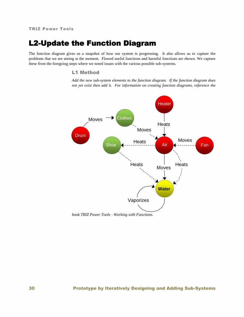
L2-Update the Function Diagram
The function diagram gives us a snapshot of how our system is progressing. It also allows us to capture the
problems that we are seeing at the moment. Flawed useful functions and harmful functions are shown. We capture
these from the foregoing steps where we noted issues with the various possible sub-systems.
L1 Method
Add the new sub-system elements to the function diagram. If the function diagram does
not yet exist then add it. For information on creating function diagrams, reference the
book TRIZ Power Tools—Working with Functions.
Water
Heater
Shoe Air Heats
Fan Moves
Clothes
Drum
Heats Moves
Heats Moves
Vaporizes
Heats
Moves
TRIZ Power Tools
Prototype by Iteratively Designing and Adding Sub-Systems 31
L2-Update the Requirements Diagram
A requirements diagram is the mirror image of a causal analysis diagram used to understand the chain of causes
when there is a problem. The difference is that the boxes are all positive descriptions of what is happening rather
than negative descriptions. Each box describes a requirement realized by elements of the sub-system.
The first time that we try to add a sub-system to the diagram, we want to get a good look at where we think that we
are going to have problems arise.
L1 Method
Step 1: Begin with a desired outcome
Step 2: Add the subsystem to the diagram. Suggestion: Each block contains positive
attributes rather than the negative attributes in a causal analysis. Suggestion: Include
the level, setting or numerical value of each attribute. Suggestion: Decompose each
level using simple models and equations where the equations provide the attributes for
the next level of decomposition. Suggestion: On each pass, start with the diagram the
way that we believe that the system will behave.
Step 3: When the diagram is done, try to understand what is not ideal about the diagram.
Note insufficient useful functions, harmful functions and contradictions.
Example—Shoe Dryer
Step 1: Begin with a desired outcome
The desired outcome is that the water removal is rapid
Step 2: Add the subsystem to the diagram. Suggestion: Each block contains positive
attributes rather than the negative attributes in a causal analysis. Suggestion: Include
the level, setting or numerical value of each attribute. Suggestion: Decompose each
level using simple models and equations where the equations provide the attributes for
the next level of decomposition. Suggestion: On each pass, start with the diagram the
way that we believe that the system will behave.
The constructed diagram is shown below.

TRIZ Power Tools
32 Prototype by Iteratively Designing and Adding Sub-Systems
Water
Removal is
Rapid
Water
Water is in
Vapor state
Air Velocity
is High
Vaporizes
Water
Shoes
Heats
Water
Dryer
Fan
Moves
Outside
Air
Shoes /
clothes
Moves
Air
Shoe
Temperature
is high
Water Temperature
is high
Air Saturation is Low
Air
Heats
Water
Requirements
Decomposition for
a Shoe Dryer
Air
Heats
Shoe
Air
Moves
Air
Temperature
is high
Fan Flow is
High
Shoe Velocity
is High
Heating
Element
Heats
Air
Shoes
Damages
Drum /
Clothes
Drum
Moves
Shoes
Shoe Velocity is Low
Damage to Drum is Low

TRIZ Power Tools
Prototype by Iteratively Designing and Adding Sub-Systems 33
Step 3: When the diagram is done, try to understand what is not ideal about the diagram.
Note insufficient useful functions, harmful functions and contradictions.
First, we note that the main air velocity is a result of the shoes and clothes being thrown
about the dryer, rather than the high velocity flow caused by the fan. By the time that the
dry air from the fan hits the shoes, it is already well mixed in the drum.
There is a harmful function between the shoes and the drum and one between the shoes
and the clothes. (Both functions were combined for brevity).
The faster the shoes move, the higher the airflow past them, but the worse the harm of the
drum and the clothes. This is a contradiction. We want the shoes to move fast and slow.
L2-Verify Crucial System Elements
Verifying the Critical Elements
We know that we have a viable system when each of the elements
for system survival is operable. The system that we are creating
must have four basic elements: an energy source; a transmission
element; a working element and a control element. Without some
form of each of these elements, the system cannot operate.
The working element operates directly on the sub-system product.
The control element senses how well the modification has
occurred.
Control Elements
Suggestions are available for the addition of control elements.
There is often a tendency to design complicated control systems.
This is only necessary with more developed and differentiated
systems in which we are running out of resources. For new systems, keep it simple. In general, the most ideal form
of control is passive control. This is because the element which senses also actuates the working element, making
the system simpler.
Line of Evolution for Control Elements
The line of evolution for adjustability4 is shown below. Once the point of feedback
5 is reached, the added benefits
of increasingly good feedback give diminishing returns and the system usually jumps to a new physical phenomenon
or to passive control.
4 Inventive Principle #15—Dynamicity: Characteristics of an object or outside environment, must be altered to provide optimal performance at each stage of an operation. If an
object is immobile, make it mobile. Make it interchangeable. Divide an object into elements capable of changing their position relative to each other.
Genrich Altshuller, The
Innovation Algorithm page 288.
5 Inventive Principle #23—Feedback: Introduce feedback. If feedback already exists, change it.
Genrich Altshuller, The Innovation Algorithm page 288.
Control
Elements
Transmission Energy
Source
Working
Element

TRIZ Power Tools
34 Prototype by Iteratively Designing and Adding Sub-Systems
Open Loop Control
Open loop control adds an actuator to change the main machine that controls the parameter. A simple controller
changes the actuator based upon environmental conditions or time. This is done in avoidance of feeding back the
main parameter being controlled because sensing elements can be very expensive.
Closed Loop Control
Closed loop control6 goes beyond open loop control by providing a device to sense the main parameter that is being
controlled. The sensor may sense the derivative of the parameter and then integrate or it may sense the integral of
the controlled parameter and then take the derivative. The control scheme then compares the level of the parameter
that is being controlled to a reference level and calculates an “error”. This error is then used in a controller to
provide a signal to the actuator that drives the main “plant”. The control laws can be simple or complicated
depending upon the accuracy required.
Passive Control
The highest form of control is passive control7
8,. The system should ideally use one physical phenomenon for
operation and control. The element that senses and controls operates about a critical point at which small changes in
input cause large changes in output or large changes in environmental conditions cause small changes in the
controlled parameter.
L1-Method
Step 1: Review the system to verify that all crucial elements shown in the above diagram
are present.
6 Inventive Principle #23—Feedback: Introduce feedback. If feedback already exists, change it.
Genrich Altshuller, The Innovation Algorithm page 288.
7 Inventive Principle #25—Self-service: An object must service itself and carry-out supplementary and repair operations. Make use of waste
material and energy. Genrich Altshuller, The Innovation Algorithm page 288.
8 Use of critical points is an extension of Standard 1-2-5. There are many physical phenomena that exhibit critical points. Operation about these
critical points allows for large forces to be created which, in turn, can be used for actuation. STANDARD 1-2-5. If it is necessary to decompose a
SFM with a magnetic field, the problem is solved by using physical effects, which are capable of “switching off” ferromagnetic properties of
substances, e.g. by demagnetizing during an impact or during heating above Curie point. Notes: The magnetic field may appear at the right
moment if a system of magnets compensating the effect of each other's field is used. When one of the magnets is demagnetized, a magnetic field
arises in the system. Example: During welding, it is difficult to insert a ferromagnetic powder in the welding zone: an electromagnetic field of a
welding current makes the particles move away from the welding zone. It is proposed to heat the powders above the Curie point to make them
non-magnetic.
Fixed Adjustable Feedback Increased Adjustability
(Continuous, Multiple)

TRIZ Power Tools
Prototype by Iteratively Designing and Adding Sub-Systems 35
Step 2: Consider Open-Loop Control. Make the tool or product adjustable if it is not
already. Consider making the control continuously adjustable. Add an actuator to the
tool or product. Add a controller which changes the level of actuation based on
operating conditions other than feeding back the main parameter that is being controlled.
Step 3: Consider Closed Loop Control
Does the modification need to be yet more precise? Add a sensor to sense the main
parameter that is being controlled. Compare this to a reference level that the parameter
is being controlled to. The whole system looks like the figure below.
If necessary, increase the number of parameters sensed. Consider increasing the order
of the variable sensed (first derivative, second derivative…).
Step 4: Consider use of Passive
Control: Identify a physical
phenomenon that senses the
parameter that is being
controlled and automatically
urges the plant to change the
parameter being controlled.
Identify the critical point around
which the system will control
the main parameter to the
desired level then move the
critical point to the desired
control point.
Reference
Error
+
-
Control
Laws Plant
Sensor
Controlled
Parameter
Control
Laws Plant
Controlled
Parameter
Human
Temperature threshold
Pressure threshold
Auditory threshold
Olfactory threshold
Personal space violation
Speed threshold
Altitude threshold
Visual thresholds
Startling point
Discomfort (A pattern or
perception that
something is out of
place)
Equilibrium threshold
Critical Points
Sheer Strength
Ultimate Strength
Tip Angle
Static Friction
Adhesive Failure point
Zero Buoyancy
Triple point
Surface Tension
Resonant Frequency
Spark point
Freezing point
Boiling point
Curie temperature

TRIZ Power Tools
36 Prototype by Iteratively Designing and Adding Sub-Systems
Example—Drying Shoes
Step 1: Review the function chain to verify that all crucial elements are present.
Step 2: Consider Open-Loop Control. Make the tool or product adjustable if it is not
already. Consider making the control continuously adjustable. Add an actuator to the
tool or product. Add a controller which changes the level of actuation based on
operating conditions other than feeding back the main parameter that is being controlled.
Since the dryer has its own internal control scheme, it will not be necessary to change
this.
Step 3: Consider Closed Loop Control
Does the modification need to be yet more precise? Add a sensor to sense the main
parameter that is being controlled. Compare this to a reference level that the parameter
is being controlled to. The whole system looks like the figure below.
If necessary, increase the number of parameters sensed. Consider increasing the order
of the variable sensed (first derivative, second derivative…).
Since the dryer has its own internal control scheme, it will not be necessary to change
this.
Step 4: Consider use of Passive Control: Identify a physical phenomenon that senses the
parameter that is being controlled and automatically urges the plant to change the
parameter being controlled. Identify the critical point around which the system will
control the main parameter to the desired level then move the critical point to the desired
control point.
Since the dryer has its own internal control scheme, it will not be necessary to change
this.
The fan
transmits the
energy to the air
The heating
coil is a second
energy source The motor is an
energy source
Air is Working
Element
Dryer thermostat is
the control element

TRIZ Power Tools
Prototype by Iteratively Designing and Adding Sub-Systems 37
L2-Iteratively Add Supporting Sub-Systems
The addition of each function and element should be treated in the same fashion as the system function was treated.
We always ask; “what is the ideal product, modification, effect and tool.”
The Positive Chain captures the objects, properties and object structures which will deliver the functions that we
need.
Method
Step 1: Follow the rules for the Positive Cause-Effect Chain to capture most of the
objects and functions which will be required.
Step 2: Add all objects according to the rules of idealizing functions.
Step 3: Identify and remove contradictions as you go.
L2-If Possible, Consider a Set-Based Approach
A set-based approach allows for multiple solutions. Each solution is evolved in its own right. Some solutions may
be revolutionary with completely new physical effects and phenomena. Others will already exist and evolve toward
the given targets and ranges. It is understood that individuals or small teams may not be able to develop multiple
solutions.
While paring down the solutions, it is important to avoid certain types of solutions. For example, solutions that
cannot be discriminated by the target market are not going to be winners.
Also avoid solutions that will lead to highly disruptive situations unless you are prepared to do battle with your
organization. This may seem somewhat narrow-minded, but experience shows that most inventors cannot fight a
product battle on one front and a cultural battle on another front.
When it comes to selecting the system that will be used, try to select for the simplest system with the fewest
components.
Method
Step 1: Identify several solution concepts that meet the super-system targets and ranges.
Step 2: Iteratively develop each system to match the targets and ranges. Communicate
the capabilities upward to the designers of the super-system. The idea is to continue to
reduce the risk of each system while keeping the largest set of solutions possible.

TRIZ Power Tools
38 Prototype by Iteratively Designing and Adding Sub-Systems
L1-Simplify the Product or Service
Simplifying the System
Before we build aesthetic prototypes (remember that they may not be required), we may want to simplify the system
somewhat. This makes building the prototype less time consuming and will also help with the manufacturing
process.
On the first few attempts, we may decide that it is not necessary to simplify in order to get an idea of whether the
concept will work. In this case, this step can be bypassed. For a deeper dive into the processes mentioned here, go
to TRIZ Power Tools—Job 4 Simplifying.
L1 Method
Determine whether simplification is required yet. If so, then go to TRIZ Power Tools—
Job #4 Simplifying.

TRIZ Power Tools
Simplify the Product or Service 39

TRIZ Power Tools
40 Investigate Manufacturing Processes and Capabilities
L1-Investigate Manufacturing
Processes and Capabilities
Investigating the Manufacturing Processes and Capabilities
Building the prototype really enhances the ability to understand how the product or service will be manufactured.
We say this, realizing that the prototype may not be using the final manufacturing process. It will, however, help
you to understand how accurately certain features need to be manufactured in order to make it work.
Ultimately, you will need to investigate how to produce or manufacture the product or service. This is usually done
be talking to people who are in the industry. Don’t be afraid to investigate new ways of manufacturing.
In the previous book, we may have learned that the constraint that we want to work on, actually exists in the
manufacturing process. If this is the case, then the manufacturing methods and prototypes are the most important
part of the innovation process. We may need to focus the full innovative creativity around manufacturing the
product or service. In fact the iterative creation of the prototype may actually have been a prototype of the
manufacturing process.
Understanding the manufacturing process is important if you are going to license or sell your idea. One of the first
things that a prospective licensee will want to know is how much it is going to cost and what sorts of costs she will
incur to modify or buy machinery to make the product. Consequently, it is important to anticipate every question
that might be asked.
The output of this book is prototypes that we can show to the customer and to the business. If we find that the cause
of the customer constraint needs to be addressed in the manufacturing process, then the prototypes that we have
already created will showcase the manufacturing process. That is not what this step is about. We need to
understand, for the sake of the business, what non-recurring and recurring costs will be required in manufacturing
the product or providing the service. Will the business need to purchase new equipment or can the existing
equipment be modified? What will be the recurring costs of manufacturing the product or providing the service? It
is very difficult for the business to determine whether to move ahead unless this information is known. Thus, there
is a need to investigate the manufacturing or production methods as part of the prototyping process.
L1 Method
Step 1: Determine whether the methods used to prototype the product or service is
indicative of the methods which will be used in full-scale production.
Step 2: If not, then search out ways to manufacture the product for the least cost
possible. This effort may need to be as inventive as determining what the product or
process should look like. Use the same methods to solve inventive problems as you would
for a product or service.
Step 3: Determine the recurring costs of the materials and labor.
Step4: Determine the modifications to existing equipment or the requirements for new
equipment. Use this to determine the non-recurring costs.
Step 5: Determine the non-recurring labor costs to design.

TRIZ Power Tools
File for Patents 41
TRIZ Power Tools
42 File for Patents
L1-File for Patents
Filing for Patents
With the manufacturing processes understood, we are now ready to file for patents or, at least, create a place holder
at the patent office with a provisional patent. While this is not always necessary or even desirable, it does provide
the maximum protection before you perform public evaluation of your prototypes. We may want to file patents for
the product and/or the production process.
Two types of patents are considered: a provisional or “poor man’s” patent and a non-provisional or regular patent.
Congress created the provisional patent in the late 90’s to help spur small business growth. A provisional patent is
basically a place holder for a filing date, since the patent examiner will not even look at it until the regular patent is
filed. (It can also serve as a substitute for building working prototypes, also called “reduction to practice”). The
provisional patent must include sufficient detail that someone “skilled in the art” could build your invention. While
it is good practice to give as much detail as possible, do not worry about flowery legal wording and drawings.
Attach legible drawings and the cover-sheet provided through the USPTO web-site and pay a fee of about $80.
Provisional patents are in effect until one year from the date of filing.
They need to be converted to a regular patent within the year or your invention is considered to be abandoned. One
strategy is to file for a provisional patent and then license the product or service. Part of the business agreement is
up-front money which can be used to file the non-provisional patent via a patent attorney or agent.
Traditional patents are much more expensive. If you are in business for yourself, it is usually difficult to justify the
expense of a non-provisional patent, before the market has proven itself. On the other hand, most large companies
have greater resources and therefore rarely bother with the added time and effort of a provisional patent.
When you have established a filing date, you are now patent pending. Write patent pending on your prototypes.
You are now free to sell, license or manufacture your invention. Understand that you are still at some risk that
someone else has already patented the idea. Your degree of risk is directly related to the depth of your patent
searching and to how close your invention is to other related patents.
The subject of patents cannot be adequately covered in this text. It is suggested that you read a book on patenting.
It is entirely possible for a lone inventor to patent his own invention and do a better job than is typically done by
professional patent attorneys and agents. However, there are a number of important things that must be learned.
Remember, you are the one that knows your invention the best.
There are a number of tests that must be overcome in order to secure a patent. The two most important tests are
novelty and non-obviousness. The novelty test is generally an easy test. We just need to answer the question: Is it
physically different than prior art? The non-obviousness test is much more difficult to pass. It must be non-obvious
to someone skilled in the art with full knowledge of all prior art, and it must be non-obvious after consulting all prior
art. Ask yourself, does the effect of the invention provide a non-obvious result? For example, does it solve a
previously unsolved problem? The practical rules of non-obviousness are documented to some degree in the
USPTO literature.
L1-Method
Step 1: Perform a patent search to determine the novelty of your invention.
Step 2: If it is sufficiently novel then file a provisional patent with the US Patent and
trademark office.

TRIZ Power Tools
File for Patents 43
Step 3: If you would like to be more certain then file a traditional patent.
L2-Perform a Patent Search
If you have not done so, it is probably a good idea to see what has already been patented to determine whether you
are violating someone else’s patent. This should have been done much earlier when trying to determine the physical
phenomena that would be used. The patent search gives a lot of information that you will need now if not earlier
such as the companies that are producing similar products, etc.
Method
Step 1: Perform a patent search to determine the patent landscape and whether your
invention may be violating someone else’s invention. If you would like more detail on
this process then consult the materials related to idealizing physical phenomena in the
step related to Idealizing Useful Subsystems.
L2-Determine a Patent Strategy
Normally, it is sufficient to file for a provisional patent before you go out to sell or license your invention.
Sometimes, the patent landscape is rockier and you may need to do more work. If you discover that your idea is not
novel in the current form, you may need to solve additional problems in order to make it novel enough.
Patent interest may go deeper than securing a single patent. Some situations require multiple patents to create a
“patent fence” to exclude competition.
Since most examiners do not want to see a patent for a product and the manufacturing method together, you may
need separate patents for these.
Method
Step 1: If there is a problem, then try to determine if there is a special angle that you can
use to get protection. Seek a professional if this is difficult for you.
Step 2: If the idea is patentable then broaden the Invention
--Broaden the Market—Do Function in more markets
--Broaden the Jobs it can help to do
--Increase Functions it can do
--Broaden the ways to implement the invention
--Broaden Physical Phenomena
--Broaden the Architecture
--Value the Solution Sets
-- Prioritize the Solution Sets

TRIZ Power Tools
44 File for Patents
Step 3: Determine whether a patent is required for the product or service and separate
one is required for the method of producing the product or service.
L2-File Provisional Patents
If you are not sure that your idea has a strong market, or you cannot afford the expense of a
regular patent application, you may want to file a provisional patent first. Provisional patents
were created in the late 90’s as a poor man’s patent. They serve as a filing date place holder
and allow the holder to be “patent pending”. Thus, the inventor to go out and find a customer.
In other words, you can test both function and marketability in public. Provisional patents are
considerably less formal than the non-provisional patents. They usually require a cover letter
provided by the patent office and an informal explanation and drawings. The weakness of the
provisional patent is that anything that was overlooked and later put into the non-provisional patent cannot claim the
filing date of the provisional patent.
Method
Step 1: Get forms from USPTO web site.
Step 2: Fill out the forms and attach the explanation of the invention along with the
drawings.
Step 3: Include a check which is about $80
Step 4: Include a self-addressed post card with check boxes for everything that you have
sent. They will check the boxes and return the card to you. Make sure the card has a
postage stamp.
Step 5: Send the package by U.S. Overnight express mail. The postage date is
considered the filing date.
Step 6: If everything is OK at USPTO then will receive filing date in 6-8 weeks. You are
now “Patent Pending”
L2-File Traditional Patents for a Small Entity
If you are certain that your idea has a strong market and you can afford the expense, you may
want to file a regular or traditional patent first. It is entirely possible for an inventor who is not
a patent agent or an attorney to file a patent. Nor is it required by the patent office. A lone
inventor can prosecute (do what it takes to secure) a patent from the USPTO. On the other
hand, you can also work with a patent agent or attorney. The cost may be as high as several
thousand dollars. If you are hiring someone to do the work, then follow the same guidelines as
the “Traditional Patent for a Large Company”. If you are doing it on your own then:
Method
Step 1: Read a good book on the subject. One such book is Patent it Yourself by attorney
David Pressman. NOLO produces this book and it can be found at Nolo.com. This book
contains forms and in-depth explanations of the finer points of patenting. Whether you
patent yourself or allow someone else to do it, you should probably read this book.
Provisional
Patent
Traditional
Patent

TRIZ Power Tools
File for Patents 45
Step 2: Follow all of the procedures described in Patent it Yourself. It is strongly
suggested that the only procedure that should be done out of sequence is the patent
search. In this book this is done during the step of determining a physical phenomenon
to deliver the function. The search helps us to determine available physical phenomena
and keeps us from putting in too much work on an idea that is not likely to go anywhere.
L2-File Traditional Patents for a Large
Company
If you work for a company, it is often the policy that a regular patent is filed first. This is
because a non-provisional patent is more complete. It is done once and has a stronger position
than the provisional patent.
Method
Step 1: Assist the company attorneys to file the patents. This
usually involves some sort of disclosure of the invention, meeting with the attorney,
disclosing drawings of the idea and providing lab notebook copies.
Step 2: Assist in the patent search. The company will usually hire a search to be done.
The patents that come back need to be reviewed. Some search firms are better than
others. If you have developed the ability to search patents yourself, you can assist.
Step 3: Review the patent application for correctness. Remember, you are the one that
truly understands how your patent works. Take the time to review it properly and give
needed feedback. Especially take the time to carefully review the claims. Create a claim
tree to help you understand the completeness of the claims. The strength of the patent
will largely depend upon the strength of the claims.
Traditional
Patent
TRIZ Power Tools
46
L1-Refine the Prototype for Public
Feedback (If Necessary)
Public testing of Prototypes
Finally, we get back to the outer loop of all that we are doing. With the prototype, we are able to go back to Book
2—Choosing Features and continue our interviewing process. With prototype in hand, we can show our idea to
potential customers and get their feedback. We want the most honest feedback possible because we are going to
sink a lot of time and money into this concept. We may also need this type of information if we are going to license
or sell the idea.
The Different Types of Prototypes
There are different types of prototypes. The first type of prototype we have already come across if we are trying to
understand a physical phenomenon. Let’s call these the Effect Prototype. These prototypes can be very crude and
simple.
A Functional Prototype is the next step up. Here, we are trying to see if we have the right parts and if it works in the
job that we are going to use it. Again, it is usually not necessary to develop a polished prototype in order to see the
how well it works in the job. We want to verify that there were no major risks left. You also want to convince
yourself that you haven’t left anything out so that your invention is ready for patent filing. You may also want to
use these prototypes to convince the business and some enlightened customers that your idea is marketable and can
be manufactured.
Finally, an Aesthetic Prototype may be necessary in order to get a less biased reaction from the using public.
Remember that some people that may want to use your product would never consider using it if it were not “socially
acceptable.” The revulsion at seeing a functional prototype might outweigh the desire to perform the job. These
prototypes can be quite expensive. Consequently, it may be necessary to wait for the company that is going to
manufacture the product to build these prototypes.
Crude and Simple for the First Round of Prototypes
Many people put too much cost and effort into Effect and Functional prototypes. Making expensive prototypes can
exhaust your resources. Discouragement often sets in and the final product may never materialize. Remember that
the purpose of these first prototypes is to convince YOU that all of the ideas work together. The added cost is often
not justified.
There are good reasons beyond cost for making the prototypes crude. The act of building the prototype causes us to
think and see things that we would normally not see. When we build expensive prototypes, it takes too long to see
what we need to see. The first prototypes will likely have flaws. This is actually good because you will still learn a
lot from them. Crude prototypes often show us what we need to know both good and bad. When we build
something that does not work, we often learn of weaknesses that could crop up in an expensive proto type that is
built correctly but at the extremes of its variability.
Another purpose of these prototypes is to help understand the relative importance of each architectural feature. The
more rapidly you can change the features, the better because this gives you a better feel for what the knobs

TRIZ Power Tools
Refine the Prototype for Public Feedback 47
(attributes or characteristics) are and how much they affect the outcome. So, just slap some stuff together and start
mixing and matching.
Remember that in the first round of prototypes, the audience is usually you. This prototype will give you the
knowledge and ultimately the courage to carry on. Be willing to make several rounds, improving a little on each
round. Even in later aesthetic versions, you are the one that needs the data and the convincing to continue.
Thinking about how to build the cheapest prototype possible is an inventive adventure and often requires a lot of
mental effort. This effort is valuable as it keeps our skills sharp and forces us to think in ways that are really helpful
to the business.
Converting from Prototype to Production
While crude is often good for prototypes, a word of warning is necessary when converting to production prototypes.
The author has seen many instances where the conversion to production did not go well. When converting a
prototype to production, designers will often make seemingly small variations from the prototypes which have
drastic consequences. For instance, it is possible to hand-make prototypes in ways that are difficult to recreate in
production. Designers may not know which characteristics are critical to proper functioning of the product and
make small changes believing that there is no obvious harm. Designers may need to make concessions due to
packaging limitations that disrupt critical features. This is not an exhaustive list of what can go wrong.
In order to avoid these problems, first be aware that they can and will likely happen. Second, build production grade
prototypes as early in the development process as possible. (The foregoing discussion relates to the research and
development stages as opposed to production stages). Development testing and production testing should be
conducted on parts that are as close to production grade as possible.
L1-Method
Step 1: Who is really the audience: the consumer, a potential licensee, an original
equipment manufacturer (OEM) or your own business managers?
Step 2: How simple is the idea to comprehend? Remember that the more difficult the
explanation, the more difficult to sell to any of the above audiences. Licensees want the
idea to be obvious to consumers. If the idea is not obvious then you or your business may
need to manufacture it. This takes more salesmanship and consequently better
prototypes. A functional prototype might be enough to convince the business, depending
upon the imagination of the critical decision makers.
Step 2: What do you need to prove to your audience? Is it the basic physics? Is it the
controllability? Is it the reliability or the aesthetics?
Step 3: Determine the minimum that must be built to prove what you need to prove to
your chosen audience.
Step 4: Build and functionally test the prototype.
Step 3: Document and witness the reduction to practice.

TRIZ Power Tools
48
L2-Refine the Aesthetic Form
The aesthetic form of the invention is often important, especially if it is a
consumer product. Notice how you react to choices that you make when you buy
among competing products. Given the choice of products having the same
function, you will likely choose the one that has the most aesthetic appeal. If
your product is not competing with any product of consequence, the aesthetic
form is used to convince the customer that the product will actually perform as
advertised. In other words, if the manufacturer has taken the time to refine the aesthetic form, surely the effort has
been expended to ensure that it works! Remember the user interface that you developed in in TRIZ Power Tools
Job #2 Choosing Features.
Method
Step 1: Draw multiple pictures in your journal showing several different aesthetic forms
of the product.
Step 2: Show the pictures to others and get their opinions.
Step 3: Since you have already filed for the patent, getting professional advice is a great
idea.
L2-Build Refined Prototypes
Once more, we build a prototype. This is a more complete and aesthetic
version. The purpose of this prototype is to convince you whether there is
sufficient public acceptance of your invention. It is also used to determine the
preferred form of the invention and perhaps the preferred manufacturing
process.
Whether you create the preferred aesthetic form or not will be determined by
your pocketbook. The closer to the final product the better, as you will be able
to better assess public reaction. This is where it pays to have a real arsenal of
tools if you are going to do it yourself.
You may also wish to employ the services of a prototype shop. This can become quite expensive and it is necessary
to create detailed drawing to convey the ideas. Often this is unnecessary if you are able to develop a reasonable
functional prototype and have good artistic representations of the final product.
L2-Method
Step 1: Research the parts that must be purchased to build the prototype: motors, fans,
electrical equipment, etc.
Step 2: Create detailed drawings of the parts. Make sure that the parts fit together. It is
usually not necessary to define detailed tolerances for professional prototype builders,
but this can help the builder to determine the cost up-front.
Step 3: Build the prototype. Remember that you can still use many of the inexpensive
materials that we have already talked about.
Journal

TRIZ Power Tools
Refine the Prototype for Public Feedback 49
Step 4: Ensure that the prototype meets all of the requirements chosen in TRIZ Power
Tools Job 2: Choosing Features.

TRIZ Power Tools
50
L1-Continue Seeking Target Market
Feedback
With the prototype, we are able to go back to Job #2—Choosing Features and continue our interviewing process
with the target market. With prototype in hand, we can show our idea to potential customers and get their feedback.
We want the most honest feedback possible because someone is going to sink a lot more time and money into this
concept. We may also need this type of information if we are going to license or sell the idea. If you can afford
public testing, you will receive a wealth of information.
While it is technically permissible to perform public testing before filing for a patent, it is suggested that public
testing take place after at least filing a provisional patent. When those who test the idea know that the invention is
patent pending, this will relieve them and you from worrying about intellectual property issues.
Even with a patent, there are pitfalls. Should you discover important features during this period, you may want to
add these features to your invention. Sometimes these ideas are suggestions brought forward by those testing your
prototype. If the change is within the scope of the present patent, you may want to amend the patent to clarify it. If
it is not within the scope, this may necessitate re-filing the patent. While performing public testing, you need to be
careful that improvements are still owned by you. This can be done in a couple of ways. First, insist that the user
only bring up problems, not solutions. Second, have the participants sign a form that forfeits their invention rights to
you. Then they are free to suggest improvements.
Remember that the inventor has one year from the time of public use or offering the invention for sale to file a
patent. The USPTO does not consider public testing to be “public use” if the testing is kept within narrow
guidelines. Keep good testing records during this time if you choose to test in public before you file for patent.
These records should be well dated and witnessed if possible. Avoid the temptation to simply use the invention in
public. If you do, note the dates.
For further information on public testing refer to the section in Job 2—Choosing Features which details public
testing of prototypes.
L1 Method
Step 1: Make prototypes that you feel comfortable showing to the public. These do not
always have to be perfect, especially if the reviewers are very forgiving. (Blocked
markets can be very forgiving).
Step 2: Show the prototypes during the procedures explained in Job 2: Choosing
features.
Step 1: Write “Patent Pending” on everything that the public can see.
Step 2: Conduct public testing of prototypes. Try not to intervene or show the best
methods for use. Also watch them perform their task or job. Note unexpected behaviors
Step 3: Ask questions about what they were trying to do and why they did it. Especially
ask about unusual behaviors.
Step 4: Continue to log test ideas and results in the journal.