Embed Size (px)
Citation preview

24-Feb-2017Date:1Version:
Triton Core Servo DriveProduct Manual
Table of Contents
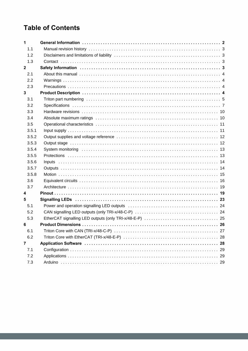
Table of Contents
1 General Information . . . . . . . . . . . . . . . . . . . . . . . . . . . . . . . . . . . . . . . . . . . . . . . . . . . . . . . . . . . . 21.1 Manual revision history . . . . . . . . . . . . . . . . . . . . . . . . . . . . . . . . . . . . . . . . . . . . . . . . . . . . . . . . . 3
1.2 Disclaimers and limitations of liability . . . . . . . . . . . . . . . . . . . . . . . . . . . . . . . . . . . . . . . . . . . . . . 3
1.3 Contact . . . . . . . . . . . . . . . . . . . . . . . . . . . . . . . . . . . . . . . . . . . . . . . . . . . . . . . . . . . . . . . . . . . . . 3
2 Safety Information . . . . . . . . . . . . . . . . . . . . . . . . . . . . . . . . . . . . . . . . . . . . . . . . . . . . . . . . . . . . . 32.1 About this manual . . . . . . . . . . . . . . . . . . . . . . . . . . . . . . . . . . . . . . . . . . . . . . . . . . . . . . . . . . . . . 4
2.2 Warnings . . . . . . . . . . . . . . . . . . . . . . . . . . . . . . . . . . . . . . . . . . . . . . . . . . . . . . . . . . . . . . . . . . . . 4
2.3 Precautions . . . . . . . . . . . . . . . . . . . . . . . . . . . . . . . . . . . . . . . . . . . . . . . . . . . . . . . . . . . . . . . . . . 4
3 Product Description . . . . . . . . . . . . . . . . . . . . . . . . . . . . . . . . . . . . . . . . . . . . . . . . . . . . . . . . . . . . 43.1 Triton part numbering . . . . . . . . . . . . . . . . . . . . . . . . . . . . . . . . . . . . . . . . . . . . . . . . . . . . . . . . . . 5
3.2 Specifications . . . . . . . . . . . . . . . . . . . . . . . . . . . . . . . . . . . . . . . . . . . . . . . . . . . . . . . . . . . . . . . . 7
3.3 Hardware revisions . . . . . . . . . . . . . . . . . . . . . . . . . . . . . . . . . . . . . . . . . . . . . . . . . . . . . . . . . . . 10
3.4 Absolute maximum ratings . . . . . . . . . . . . . . . . . . . . . . . . . . . . . . . . . . . . . . . . . . . . . . . . . . . . . 10
3.5 Operational characteristics . . . . . . . . . . . . . . . . . . . . . . . . . . . . . . . . . . . . . . . . . . . . . . . . . . . . . 11
3.5.1 Input supply . . . . . . . . . . . . . . . . . . . . . . . . . . . . . . . . . . . . . . . . . . . . . . . . . . . . . . . . . . . . . . . . . 11
3.5.2 Output supplies and voltage reference . . . . . . . . . . . . . . . . . . . . . . . . . . . . . . . . . . . . . . . . . . . . 12
3.5.3 Output stage . . . . . . . . . . . . . . . . . . . . . . . . . . . . . . . . . . . . . . . . . . . . . . . . . . . . . . . . . . . . . . . . 12
3.5.4 System monitoring . . . . . . . . . . . . . . . . . . . . . . . . . . . . . . . . . . . . . . . . . . . . . . . . . . . . . . . . . . . 13
3.5.5 Protections . . . . . . . . . . . . . . . . . . . . . . . . . . . . . . . . . . . . . . . . . . . . . . . . . . . . . . . . . . . . . . . . . 13
3.5.6 Inputs . . . . . . . . . . . . . . . . . . . . . . . . . . . . . . . . . . . . . . . . . . . . . . . . . . . . . . . . . . . . . . . . . . . . . 14
3.5.7 Outputs . . . . . . . . . . . . . . . . . . . . . . . . . . . . . . . . . . . . . . . . . . . . . . . . . . . . . . . . . . . . . . . . . . . . 14
3.5.8 Motion . . . . . . . . . . . . . . . . . . . . . . . . . . . . . . . . . . . . . . . . . . . . . . . . . . . . . . . . . . . . . . . . . . . . . 15
3.6 Equivalent circuits . . . . . . . . . . . . . . . . . . . . . . . . . . . . . . . . . . . . . . . . . . . . . . . . . . . . . . . . . . . . 16
3.7 Architecture . . . . . . . . . . . . . . . . . . . . . . . . . . . . . . . . . . . . . . . . . . . . . . . . . . . . . . . . . . . . . . . . . 19
4 Pinout . . . . . . . . . . . . . . . . . . . . . . . . . . . . . . . . . . . . . . . . . . . . . . . . . . . . . . . . . . . . . . . . . . . . . . . 195 Signalling LEDs . . . . . . . . . . . . . . . . . . . . . . . . . . . . . . . . . . . . . . . . . . . . . . . . . . . . . . . . . . . . . . 23
5.1 Power and operation signalling LED outputs . . . . . . . . . . . . . . . . . . . . . . . . . . . . . . . . . . . . . . . 24
5.2 CAN signalling LED outputs (only TRI-x/48-C-P) . . . . . . . . . . . . . . . . . . . . . . . . . . . . . . . . . . . . 24
5.3 EtherCAT signalling LED outputs (only TRI-x/48-E-P) . . . . . . . . . . . . . . . . . . . . . . . . . . . . . . . . 25
6 Product Dimensions . . . . . . . . . . . . . . . . . . . . . . . . . . . . . . . . . . . . . . . . . . . . . . . . . . . . . . . . . . . 266.1 Triton Core with CAN (TRI-x/48-C-P) . . . . . . . . . . . . . . . . . . . . . . . . . . . . . . . . . . . . . . . . . . . . . 27
6.2 Triton Core with EtherCAT (TRI-x/48-E-P) . . . . . . . . . . . . . . . . . . . . . . . . . . . . . . . . . . . . . . . . . 28
7 Application Software . . . . . . . . . . . . . . . . . . . . . . . . . . . . . . . . . . . . . . . . . . . . . . . . . . . . . . . . . . 287.1 Configuration . . . . . . . . . . . . . . . . . . . . . . . . . . . . . . . . . . . . . . . . . . . . . . . . . . . . . . . . . . . . . . . . 29
7.2 Applications . . . . . . . . . . . . . . . . . . . . . . . . . . . . . . . . . . . . . . . . . . . . . . . . . . . . . . . . . . . . . . . . . 29
7.3 Arduino . . . . . . . . . . . . . . . . . . . . . . . . . . . . . . . . . . . . . . . . . . . . . . . . . . . . . . . . . . . . . . . . . . . . 29
1 General Information

Triton Core Servo Drive | Product Manual
INGENIA | ingeniamc.com/support | 23-Feb-2017 3
1 General Information
1.1 Manual revision history
Revision Release Date Changes PDF
v1 February 2017 Preliminary draft. Download
For the most up to date information use the online . The PDF manual is generated only after major Product Manualchanges.Please refer to for information on previous hardware revisions and changes.product hardware revisions
1.2 Disclaimers and limitations of liability
The information contained within this document contains proprietary information belonging to .INGENIA-CAT S.L.Such information is supplied solely for the purpose of assisting users of the product in its installation.INGENIA-CAT S.L. rejects all liability for errors or omissions in the information or the product or in other documents mentioned in this document.The text and graphics included in this document are for the purpose of illustration and reference only. The specifications on which they are based are subject to change without notice.This document may contain technical or other types of inaccuracies.The information contained within this document is subject to change without notice and should not be construed as a commitment by . INGENIA-CAT S.L. INGENIA-CAT
assumes no responsibility for any errors that may appear in this document.S.L.Some countries do not allow the limitation or exclusion of liability for accidental or consequential damages, meaning that the limits or exclusions stated above may not be valid in some cases.
1.3 Contact
INGENIA-CAT S.L.8-14 Marie CurieAdvanced Industry Park08042 BarcelonaSpainTelephone: +34 932 917 682E-mail: [email protected] site: www.ingeniamc.com
2 Safety Information

Triton Core Servo Drive | Product Manual
4 INGENIA | ingeniamc.com/support | 23-Feb-2017
2 Safety Information
2.1 About this manual
Read carefully this chapter to raise your awareness of potential risks and hazards when working with the Triton Servo Drive.To ensure maximum safety in operating the Triton Servo Drive, it is essential to follow the procedures included in this guide. This information is provided to protect users and their working area when using the Triton Servo Drive, as well as other hardware that may be connected to it. Please read this chapter carefully before starting the installation process.
2.2 Warnings
The following statements should be considered to avoid serious injury to those individuals performing the procedures and/or damage to the equipment:
To prevent the formation of electric arcs, as well as dangers to personnel and electrical contacts, never connect/disconnect the Triton Servo Drive while the power supply is on.Disconnect the Triton Servo Drive from all power sources before proceeding with any possible wiring change.After turning off the power and disconnecting the equipment power source, wait at least 10 seconds before touching any parts of the controller that are electrically charged or hot.
2.3 Precautions
The following statements should be considered to avoid serious injury to those individuals performing the procedures and/or damage to the equipment:
The Triton Servo Drive components temperature may exceed 100 ºC during operation.Some components become electrically charged during and after operation.The power supply connected to this controller should comply with the parameters specified in this document.When connecting the Triton Servo Drive to an approved power source, do so through a line that is separate from any possible dangerous voltages, using the necessary insulation in accordance with safety standards.High-performance motion control equipment can move rapidly with very high forces. Unexpected motion may occur especially during product commissioning. Keep clear of any operational machinery and never touch them while they are working.Do not make any connections to any internal circuitry. Only connections to designated connectors are allowed.All service and maintenance must be performed by qualified personnel.Before turning on the Triton Servo Drive, check that all safety precautions have been followed, as well as the installation procedures.
3 Product Description
Triton Core Servo Drive | Product Manual
INGENIA | ingeniamc.com/support | 23-Feb-2017 5
3 Product Description
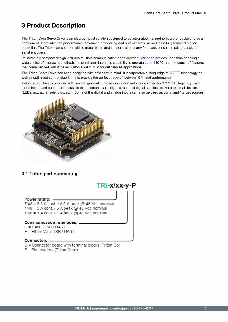
The Triton Core Servo Drive is an ultra-compact solution designed to be integrated in a motherboard or backplane as a component. It provides top performance, advanced networking and built-in safety, as well as a fully featured motion controller. The Triton can control multiple motor types and supports almost any feedback sensor including absolute serial encoders.Its incredibly compact design includes multiple communication ports carrying , and thus enabling a CANopen protocolwide choice of interfacing methods. Its small form factor, its capability to operate up to 110 ºC and the bunch of features that come packed with it makes Triton a valid OEM for critical-size applications.The Triton Servo Drive has been designed with efficiency in mind. It incorporates cutting-edge MOSFET technology as well as optimised control algorithms to provide the perfect trade-off between EMI and performance.Triton Servo Drive is provided with several general purpose inputs and outputs designed for 3.3 V TTL logic. By using these inputs and outputs it is possible to implement alarm signals, connect digital sensors, activate external devices (LEDs, actuators, solenoids, etc.). Some of the digital and analog inputs can also be used as command / target sources.
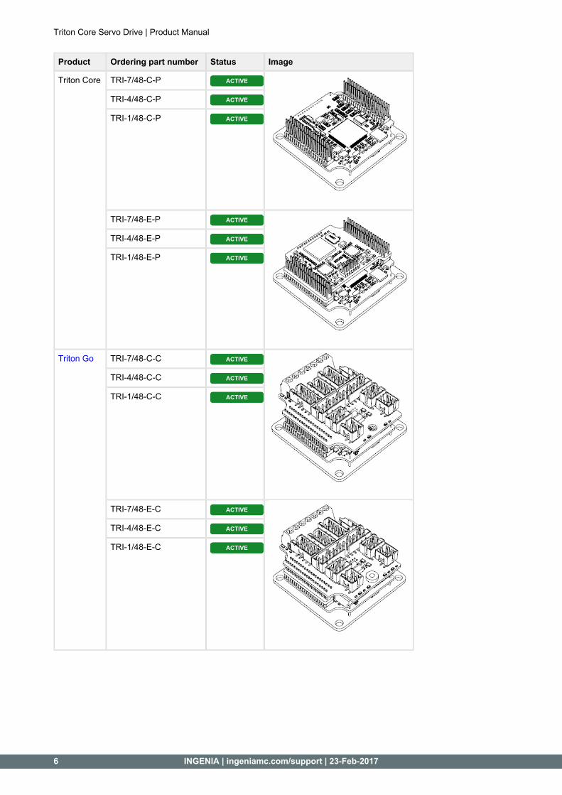
3.1 Triton part numbering
Triton Core Servo Drive | Product Manual
6 INGENIA | ingeniamc.com/support | 23-Feb-2017
Product Ordering part number Status Image
Triton Core TRI-7/48-C-P ACTIVE
TRI-4/48-C-P ACTIVE
TRI-1/48-C-P ACTIVE
TRI-7/48-E-P ACTIVE
TRI-4/48-E-P ACTIVE
TRI-1/48-E-P ACTIVE
Triton Go TRI-7/48-C-C ACTIVE
TRI-4/48-C-C ACTIVE
TRI-1/48-C-C ACTIVE
TRI-7/48-E-C ACTIVE
TRI-4/48-E-C ACTIVE
TRI-1/48-E-C ACTIVE

Triton Core Servo Drive | Product Manual
INGENIA | ingeniamc.com/support | 23-Feb-2017 7
Changes in Part NumbersPart numbers have changed from Triton version due to a current re-scaling of the whole product range. 1.0.0Follow this equivalence to identify your old Triton:
Version 1.0.0 → 1.1.0 or later
TRI-8/48-C-P TRI-7/48-C-P→ TRI-2/48-C-P TRI-4/48-C-P→ TRI-0.5/48-C-P TRI-1/48-C-P→
TRI-8/48-E-P TRI-7/48-E-P→ TRI-2/48-E-P TRI-4/48-E-P→ TRI-0.5/48-E-P TRI-1/48-E-P→
TRI-8/48-C-C TRI-7/48-C-C→ TRI-2/48-C-C TRI-4/48-C-C→ TRI-0.5/48-C-C TRI-1/48-C-C→
TRI-8/48-E-C TRI-7/48-E-C→ TRI-2/48-E-C TRI-4/48-E-C→ TRI-0.5/48-E-C TRI-1/48-E-C→
3.2 Specifications
A list of features of the Triton Core Servo Drive is shown next. For further details, please check the Operational section below.characteristics
Electrical and power specifications
Part number → TRI-1/48-y-P TRI-4/48-y-P TRI-7/48-y-P
Power supply voltage +8 V to +48 VDC DC
Transient peak voltage 65 VDC
Internal DC bus capacitance
20 µF
Minimum motor inductance
200 µH(Triton still can control motors with lower inductances. Check the from Knowledge BaseIngenia)
Nominal phase continuous current (BLDC mode)
A0.67 RMS 3.33 ARMS
(with heatsink)
5.6 ARMS
(with heatsink)
Nominal phase continuous current (DC mode)
1 ADC 5 ADC
(with heatsink)
6.3 ADC
(with heatsink)
Maximum phase peak current
1 ADC
(continuous)
5 ADC
(continuous, with heatsink)
8.5 ADC
(5 s, with heatsink)
Current sense range ± 1.02 A ± 5.10 A ± 12.7 A
Current sense resolution 1.99 mA/count 9.96 mA/count 24.8 mA/count
Triton Core Servo Drive | Product Manual
8 INGENIA | ingeniamc.com/support | 23-Feb-2017
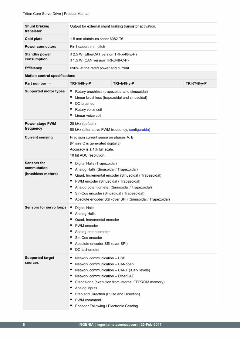
Shunt braking transistor
Output for external shunt braking transistor activation.
Cold plate 1.5 mm aluminum sheet 6082-T6.
Power connectors Pin headers mm pitch
Standby power consumption
≤ 2.5 W (EtherCAT version TRI-x/48-E-P)≤ 1.5 W (CAN version TRI-x/48-C-P)
Efficiency >96% at the rated power and current
Motion control specifications
Part number → TRI-1/48-y-P TRI-4/48-y-P TRI-7/48-y-P
Supported motor types Rotary brushless (trapezoidal and sinusoidal)Linear brushless (trapezoidal and sinusoidal)DC brushedRotary voice coilLinear voice coil
Power stage PWM frequency
20 kHz (default)80 kHz (alternative PWM frequency, )configurable
Current sensing Precision current sense on phases A, B.(Phase C is generated digitally)Accuracy is ± 1% full scale.10 bit ADC resolution.
Sensors for commutation(brushless motors)
Digital Halls (Trapezoidal)Analog Halls (Sinusoidal / Trapezoidal)Quad. Incremental encoder (Sinusoidal / Trapezoidal)PWM encoder (Sinusoidal / Trapezoidal)Analog potentiometer (Sinusoidal / Trapezoidal)Sin-Cos encoder (Sinusoidal / Trapezoidal)Absolute encoder SSI (over SPI) (Sinusoidal / Trapezoidal)
Sensors for servo loops Digital HallsAnalog HallsQuad. Incremental encoderPWM encoderAnalog potentiometerSin-Cos encoderAbsolute encoder SSI (over SPI)DC tachometer
Supported target sources
Network communication – USBNetwork communication – CANopenNetwork communication – UART (3.3 V levels)Network communication – EtherCATStandalone (execution from internal EEPROM memory)Analog inputsStep and Direction (Pulse and Direction)PWM commandEncoder Following / Electronic Gearing

Triton Core Servo Drive | Product Manual
INGENIA | ingeniamc.com/support | 23-Feb-2017 9
Inputs/outputs and protections
Part number → TRI-1/48-y-P TRI-4/48-y-P TRI-7/48-y-P
Inputs and outputs General purpose:
4 x non-isolated single-ended digital inputs. 3.3 V levels, 5.5 V tolerant2 x non-isolated high speed differential digital inputs. 3.3 V levels, 5.5 V tolerant2 x single-ended analog inputs. 12 bits, 0 V to 3.3 V range, 5.5 V tolerant6 x push-pull digital outputs. 3.3 V levels, 5.5 V tolerant.
Dedicated:
1 x non-isolated Torque OFF dedicated digital input. 3.3 V levels, 5.5 V tolerant6 x push-push LED outputs. See and Signalling LEDs Operational characteristicssections for more details.
Output supplies:
1 x 5 V output supply for powering external circuitry (up to 200 mA)1 x 3.3 V output supply for powering external circuitry (up to 50 mA)
Protections User configurable:
DC bus over-voltageDC bus under-voltageDrive over-temperatureDrive under-temperatureOver-current
Overload (I t)2
Short-circuit protections:
Phase to DC busPhase to phasePhase to GND
Mechanical limits for homing functionsHall sequence/combination errorEncoder broken wire input (for use along external circuitry)ESD protections in all inputs, outputs, feedbacks and communicationsEMI protections (noise filters) in all inputs and feedbacksHigh power transient voltage suppressor for short braking (600 W peak TVS diode)Can drive an external power braking resistor in case of re-injection by means of an external switched element.
Motor brake Motor brake output (by means of an external switched element) through digital outputs.
Communications
Part number → TRI-x/48-C-P TRI-x/48-E-P
USB USB 2.0. The board can be supplied from USB for configuration purposes but will not power the motor.
Serial UART (3.3 V levels, by default: 115200 bps, 8 data bits, no parity, 1 stop bit, no flux control)
CANopen Available at 3.3 V levels, non-isolated. RX and TX pins shall be connected to external CAN transceiver (default baud rate is 1 Mbps).CiA-301, CiA-303, CiA-305, CiA-306 and CiA-402 compliant.
-
EtherCAT - Available (magnetics are not included)

Triton Core Servo Drive | Product Manual
10 INGENIA | ingeniamc.com/support | 23-Feb-2017
Environmental and mechanical specifications
Part number → TRI-x/48-C-P TRI-x/48-E-P
Cold plate temperature -40 ºC to +85 ºC full current (with appropriate heatsink)+85 ºC to +110 ºC derated current
Maximum humidity 5% - 85% non-condensing
Horizontal dimensions 43 mm x 43 mm
Body height 8.64 mm
Pin length 7.24 mm
Weight 22 g 26 g
ErrataFirst version of the datasheet indicated a maximum phase peak current of 13 A (2 s) which is incorrect. RMS Also the Find the latest datasheet available .TRI-4/48-y-P was underrated. here
3.3 Hardware revisions
Hardware revision
Individual board references
Description and changes
1.0.0August 2016
i039-01H1-1.0.0i039-01H2-1.0.0
First product release.
1.1.0November 2016
i039-01H1-1.1.0i039-01H2-1.0.0
Changed product current range naming (current resolution and range is exactly the same as before)
TRI-0.5/48 becomes TRI-1/48TRI-2/48 becomes TRI-4/48TRI-8/48 becomes TRI-7/48
Features added:
Analog Halls feedbackAnalog (Sin-Cos) encoder feedback
Identifying the hardware revisionHardware revision is screen printed on the board.
3.4 Absolute maximum ratings
The following information represent the environmental and electrical limits of Triton Core. Notice this does not represent an operational conditions limit, but a limit before References to pin names and pin permanent damage or destruction. group names can be found in the section.Pinout

Triton Core Servo Drive | Product Manual
INGENIA | ingeniamc.com/support | 23-Feb-2017 11
Over operating free-air temperature range unless otherwise noted.
Parameter MIN MAX UNIT
V , VBUS(CONT) LOGIC(CONT) V_BUS or V_LOGIC to GND_P in continuous mode -0.3 54 V
V ,VBUS(TRANS) LOGIC(TRANS) V_BUS or V_LOGIC to GND_P in transient mode -0.3 65 V
VUSB USB_SUPPLY to GND_D -0.3 5.5 V
VPE(GND) PE to GND_P -250 250 V
VPE(BUS) PE to V_BUS -250 250 V
V3.3VPINS 3.3 V tolerant signal pins to GND_D *1 -0.3 3.5 V
V5VPINS 5 V tolerant signal pins to GND_D *2 -5.5 5.5 V
VECAT(LED) LED_ECAT_LINKx to GND_D -0.5 6.5 V
VECAT(BUS) PHY0_x or PHY1_x to GND_D -0.5 3.7 V
VGND GND_P to GND_D *3 0 0 V
IPH(MAX) Phase current short-circuit protection threshold *4 -13 13 A
TOTP Power stage built-in Over-Temperature Protection (Hardware) *5 — 150 ºC
TSTORAGE Maximum storage temperature -40 125 ºC
Note 1: +3.3V_D, +3.3V_REF_OUT, ABS_ENCODER_x, #ABS_ENCODER_CS, USB_DATAx, SHUNT_DRIVE_OUT, UART_x, CAN_TTL_xNote 2: +5V_D, INPUT_x, HS_INPUT_x, ANALOG_IN_x, ENCODER_x, OUTPUT_x, LED_x, #BROKEN_WIRE_IN, #TORQUE_OFF_IN, MOTOR_TEMP_IN, HALL_xNote 3: GND_P and GND_D are internally connected on a single point. Please keep these nets separated on the interface board to prevent noise problems.Note 4: Absolute maximum current for all part numbersNote 5: Absolute maximum junction temperature
3.5 Operational characteristics
The following information represent the recommended operation limits of Triton Core, among which its response will remain between known boundaries. References to pin names and pin group names can be found in the section.PinoutFor all the following characteristics T = 25 ºC, V = 48 V, f = 20 kHz, 1.2 ºC/W heatsink attached, unless A BUS SWotherwise noted.
3.5.1 Input supply
Parameter Conditions / Comments MIN TYP MAX UNIT
VBUS Power supply voltage range Supply to power systems through pin V_BUS
8 — 48 V
VLOGIC Logic supply voltage range Supply to logic systems through pin V_LOGIC
8 — 48 V
VUSB USB supply voltage range Supply to logic systems through pin 4.5 — 5.5 V

Triton Core Servo Drive | Product Manual
12 INGENIA | ingeniamc.com/support | 23-Feb-2017
IUSB
(CAN)
USB supply current (TRI-x/48-C-P)
USB_SUPPLY = 5 VNote that the ECAT version cannot be powered by USB only.
— 300 500 mA
CBUS Internal DC bus capacitance 16 20 24 µF
PSTB
(CAN)
Standby power consumption (TRI-x/48-C-P)
Power stage disabled — — 1.5 W
PSTB
(ECAT)
Standby power consumption (TRI-x/48-E-P)
Power stage disabled — — 2.5 W
3.5.2 Output supplies and voltage reference
Parameter Conditions / Comments MIN TYP MAX UNIT
V5V +5V_D output voltage 4.75 5 5.25 V
V3.3V +3.3V_D output voltage 3.23 3.3 3.37 V
V3.3VREF +3.3V_REF_OUT output voltage Specified at full temperature range /Typical error at 25ºC is ±0.2%.
3.28 3.3 3.32 V
I5V +5V_D output current *1 0 — 200 mA
I3.3V +3.3V_D output current *1 0 — 50 mA
I3.3VREF +3.3V_REF_OUT output current *1 0 — 10 mA
Note 1: Can withstand continuous short-circuit. Rearms after cool down time < 10 s.
3.5.3 Output stage
Parameter Conditions / Comments MIN TYP MAX UNIT
IDC(TRI-
1)
Continuous phase current in DC mode (TRI-1/48-y-P)
no heatsink required. Limited by ADC range.
-1 — 1 ADC
ITRA
(TRI-1)
Continuous phase current in Trapezoidal mode (TRI-1/48-y-P)
no heatsink required. Limited by ADC range.
— — 0.67 ARMS
ISIN(TRI-
1)
Continuous phase current in Sinusoidal mode (TRI-1/48-y-P)
no heatsink required. Limited by ADC range.
— — 0.71 ARMS
IDC(TRI-
4)
Continuous phase current in DC mode (TRI-4/48-y-P)
Limited by ADC range. -5 — 5 ADC
ITRA
(TRI-4)
Continuous phase current in Trapezoidal mode (TRI-4/48-y-P)
Limited by ADC range. — — 3.33 ARMS
ISIN(TRI-
4)
Continuous phase current in Sinusoidal mode (TRI-4/48-y-P)
Limited by ADC range. — — 3.54 ARMS
IDC(TRI-
7)
Continuous phase current in DC mode (TRI-7/48-y-P)
-6.3 — 6.3 ADC

Triton Core Servo Drive | Product Manual
INGENIA | ingeniamc.com/support | 23-Feb-2017 13
ITRA
(TRI-7)
Continuous phase current in Trapezoidal mode (TRI-7/48-y-P)
— — 5.6 ARMS
ISIN(TRI-
7)
Continuous phase current in Sinusoidal mode (TRI-7/48-y-P)
— — 5.6 ARMS
IPK(TRI-
1)
Peak phase current (TRI-1/48-y-P) Peak time = continuous.No heatsink required. Limited by ADC range.
-1 — 1 ADC
IPK(TRI-
4)
Peak phase current (TRI-4/48-y-P) Peak time = continuous. Limited by ADC range.
-5 — 5 ADC
IPK(TRI-
7)
Peak phase current (TRI-7/48-y-P) Peak time = 5 s -8.5 — 8.5 ADC
ηNOM Efficiency Phase current = 7 ARMS — — 97 %
3.5.4 System monitoring
Parameter Conditions / Comments
MIN TYP MAX UNIT
IRANGE(TRI-1) Phase current sensing range (TRI-1/48-y-P) -1.02 — 1.02 A
IRANGE(TRI-4) Phase current sensing range (TRI-4/48-y-P) -5.1 — 5.1 A
IRANGE(TRI-7) Phase current sensing range (TRI-7/48-y-P) -12.7 — 12.7 A
ISENSE(TRI-1) Phase current sensing sensitivity (TRI-1/48-y-P)
— 1.99 — mA/count
ISENSE(TRI-4) Phase current sensing sensitivity (TRI-4/48-y-P)
— 9.96 — mA/count
ISENSE(TRI-7) Phase current sensing sensitivity (TRI-7/48-y-P)
— 24.8 — mA/count
IERR Phase current sensing tolerance (all part numbers)
— ±1 ±2 %
VMON DC bus voltage reading range 0 — 73.6 V
VERR DC bus voltage reading tolerance — ±1 ±3 %
TERR Board temperature reading tolerance — — ±5 %
3.5.5 Protections
Parameter Conditions / Comments MIN TYP MAX UNIT
VUSER User-configurable over / under voltage protection limits
6 — 65 V
TUSER User-configurable over / under temperature protection limits
Board temperature -40 — 110 ºC
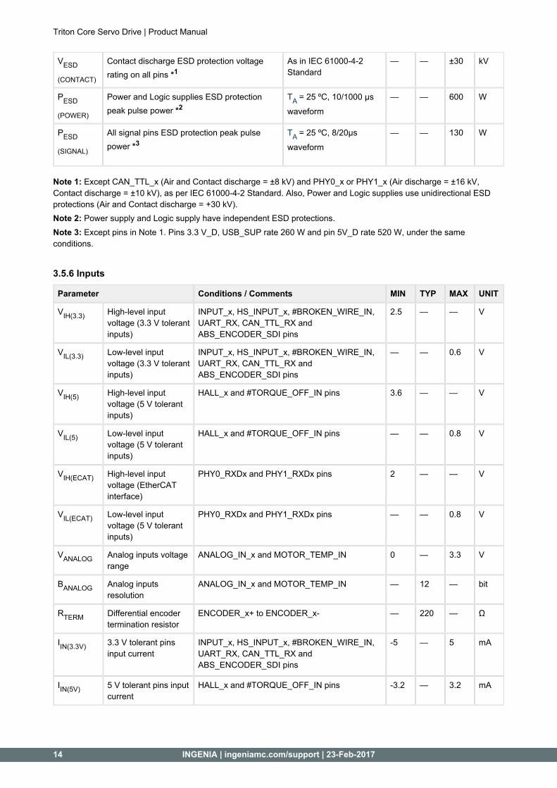
VESD(AIR) Air discharge ESD protection voltage rating on all pins *1
As in IEC 61000-4-2 Standard
— — ±30 kV
Triton Core Servo Drive | Product Manual
14 INGENIA | ingeniamc.com/support | 23-Feb-2017
VESD
(CONTACT)
Contact discharge ESD protection voltage rating on all pins *1
As in IEC 61000-4-2 Standard
— — ±30 kV
PESD
(POWER)
Power and Logic supplies ESD protection peak pulse power *2
= 25 ºC, 10/1000 µs TA waveform
— — 600 W
PESD
(SIGNAL)
All signal pins ESD protection peak pulse power *3
= 25 ºC, 8/20μs TA waveform
— — 130 W
Note 1: Except CAN_TTL_x (Air and Contact discharge = ±8 kV) and PHY0_x or PHY1_x (Air discharge = ±16 kV, Contact discharge = ±10 kV), as per IEC 61000-4-2 Standard. Also, Power and Logic supplies use unidirectional ESD protections (Air and Contact discharge = +30 kV).
Power supply and Logic supply have independent ESD protections.Note 2: Except pins in Note 1. Pins 3.3 V_D, USB_SUP rate 260 W and pin 5V_D rate 520 W, under the same Note 3:
conditions.
3.5.6 Inputs
Parameter Conditions / Comments MIN TYP MAX UNIT
VIH(3.3) High-level input voltage (3.3 V tolerant inputs)
INPUT_x, HS_INPUT_x, #BROKEN_WIRE_IN, UART_RX, CAN_TTL_RX and ABS_ENCODER_SDI pins
2.5 — — V
VIL(3.3) Low-level input voltage (3.3 V tolerant inputs)
INPUT_x, HS_INPUT_x, #BROKEN_WIRE_IN, UART_RX, CAN_TTL_RX and ABS_ENCODER_SDI pins
— — 0.6 V
VIH(5) High-level input voltage (5 V tolerant inputs)
HALL_x and #TORQUE_OFF_IN pins 3.6 — — V
VIL(5) Low-level input voltage (5 V tolerant inputs)
HALL_x and #TORQUE_OFF_IN pins — — 0.8 V
VIH(ECAT) High-level input voltage (EtherCAT interface)
PHY0_RXDx and PHY1_RXDx pins 2 — — V
VIL(ECAT) Low-level input voltage (5 V tolerant inputs)
PHY0_RXDx and PHY1_RXDx pins — — 0.8 V
VANALOG Analog inputs voltage range
ANALOG_IN_x and MOTOR_TEMP_IN 0 — 3.3 V
BANALOG Analog inputs resolution
ANALOG_IN_x and MOTOR_TEMP_IN — 12 — bit
RTERM Differential encoder termination resistor
ENCODER_x+ to ENCODER_x- — 220 — Ω
IIN(3.3V) 3.3 V tolerant pins input current
INPUT_x, HS_INPUT_x, #BROKEN_WIRE_IN, UART_RX, CAN_TTL_RX and ABS_ENCODER_SDI pins
-5 — 5 mA
IIN(5V) 5 V tolerant pins input current
HALL_x and #TORQUE_OFF_IN pins -3.2 — 3.2 mA
3.5.7 Outputs

Triton Core Servo Drive | Product Manual
INGENIA | ingeniamc.com/support | 23-Feb-2017 15
3.5.7 Outputs
Parameter Conditions / Comments
MIN TYP MAX UNIT
VOH High-level voltage on output pins *1 I = 50 μAOUTPUT 2.3 — — V
VOL Low-level voltage on output pins *1 I = -50 μAOUTPUT — — 0.5 V
IOUT(3.3V) Output current on 3.3 V tolerant pins *2 -5 — 5 mA
IOUT(5V) Output current on 5 V tolerant pins *3 -2 — 2 mA
VOH(ECAT) High-level voltage on PHY0_TXDx and pinsPHY1_TXDx
2.4 — — V
VOL(ECAT) Low-level voltage on PHY0_TXDx and pinsPHY1_TXDx
— — 0.4 V
VOH
(ECAT_LED)
High-level voltage on LED_ECAT_LINKx pins I = 50 μAECAT_LED 3.2 — — V
VOL
(ECAT_LED)
Low-level voltage on LED_ECAT_LINKx pins I = -50 μAECAT_LED — — 0.1 V
IECAT_LED LED_ECAT_LINKx pins output current -8 — 8 mA
Note 1: Applies to pins OUTPUT_x, SHUNT_DRIVE_OUT, UART_TX, CAN_TTL_TX, #ABS_ENCODER_CS, ABS_ENCODER_SDO, ABS_ENCODER_SCK, LED_CAN_RUN / LED_ECAT_RUN, LED_CAN_ERROR / LED_ECAT_ERROR, LED_FAULT/#OKNote 2: Applies to pins SHUNT_DRIVE_OUT, UART_TX, CAN_TTL_TX, ABS_ENCODER_x, #ABS_ENCODER_CS, USB_DATAxNote 3: Applies to pins OUTPUT_x, LED_CAN_RUN / LED_ECAT_RUN, LED_CAN_ERROR / LED_ECAT_ERROR, LED_FAULT/#OK
3.5.8 Motion
Parameter Conditions / Comments MIN TYP MAX UNIT
fSW Default power stage switching frequency — 20 — kHz
fSW
(RANGE)
Power stage switching frequency configurable range *1
20 — 80 kHz
fTORQUE Torque loop refresh frequency — 10 — kHz
fSERVO Position / velocity loops refresh frequency — 1 — kHz
fERR Frequency tolerance Over operating temperature range
— — ±150 ppm
DMAX Maximum DC Bus utilisation (duty) — 95 — %
Note 1: Switching frequencies different from default are provided only under demand.

Triton Core Servo Drive | Product Manual
16 INGENIA | ingeniamc.com/support | 23-Feb-2017
3.6 Equivalent circuits
Equivalent circuit Function Associated pins
f (-3dB)C Max. sample rate
Digital inputs. INPUT_x 80 kHz ksps1
High speed digital Inputs.
HS_INPUT_x
- Msps20
Analog inputs. ANALOG_IN_x
8 kHz ksps10
Absolute encoder (SPI) chip select.
#ABS_ENCODER_CS
- -
Digital hall inputs *1 HALL_x 159 kHz ksps10
Analog hall inputs *1 HALL_x 10 kHz ksps10
Motor temperature input *2
MOTOR_TEMP_IN
0.8 kHz 10 ksps

Triton Core Servo Drive | Product Manual
INGENIA | ingeniamc.com/support | 23-Feb-2017 17
Torque Off input. #TORQUE_OFF_IN
- -
Encoder broken wire protection input.
#BROKEN_WIRE_IN
- ksps1
Analog and digital encoder inputs. *3
ENCODER_x
6 MHz(Firmware glitch filter up to 30 MHz)
10 ksps
Equivalent circuit Function Associated pins
Max. baud rate
UART and CAN interface.
UART_RXUART_TXCAN_TTL_RX
- Mbps1
CAN transmitter line. CAN_TTL_TX
- Mbps1
EtherCAT interface. PHY0_x and PHY1_xLED_ECAT_LINKx
- 100 Mbps( PHY0_x and PHY1_x)
Absolute encoder (SPI) interface.
ABS_ENCODER_SDIABS_ENCODER_SDOABS_ENCODER_SCK
- bps2 M (SSI encoder max. 1 kHz)
USB interface. Includes ESD protections.
USB_DATA+USB_DATA-
- bps12 M

Triton Core Servo Drive | Product Manual
18 INGENIA | ingeniamc.com/support | 23-Feb-2017
Equivalent circuit Function Associated pins
- Max. output frequency
Digital & LED outputs. Active high at 3.3V.
OUTPUT_xLED_CAN_RUN / LED_ECAT_RUNLED_CAN_ERROR / LED_ECAT_ERRORLED_FAULT/#OK
- 1 kHz(only OUTPUT_x pins)
Shunt braking transistor output. Use a logic level power MOSFET to connect an external braking resistor *4
SHUNT_DRIVE_OUT
- 20 kHz
Note 1: Digital halls and Analog halls share the same input pins. The pull-up resistor is only enabled when Digital halls are selected as feedback source.Note 2: The 967.7 Ω pull-up resistor can be set to 30 kΩ to improve sensing a PTC thermistor of a higher nominal resistance. Contact for more info.Ingenia SupportNote 3: Analog and Digital encoder share the same input pins. In any case, differential encoders use both positive and negative terminals, while single-ended encoders only use the positive terminal. See the section for more Pinoutinformation.Note 4: It is recommended to set the braking resistor PWM duty to 100 %. In this case, the switching frequency depends on the characteristics of the re-injection or braking action itself.

Triton Core Servo Drive | Product Manual
INGENIA | ingeniamc.com/support | 23-Feb-2017 19
3.7 Architecture
This diagram represent the main hardware elements of Triton Core, and how they relate to each other.
4 Pinout
Triton Core Servo Drive | Product Manual
20 INGENIA | ingeniamc.com/support | 23-Feb-2017
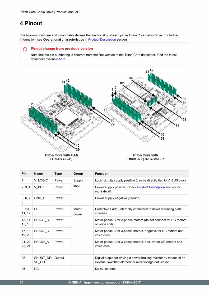
4 Pinout
The following diagram and pinout table defines the functionality of each pin in Triton Core Servo Drive. For further information, see in section.Operational characteristics Product Description
Pinout change from previous versionNote that the pin numbering is different from the first version of the Triton Core datasheet. Find the latest datasheet available .here
Pin Name Type Group Function
1 V_LOGIC Power Supplyinput
Logic circuits supply positive (can be directly tied to V_BUS pins)
2, 3, 4 V_BUS Power Power supply positive. Check section for Product Descriptionmore detail
5, 6, 7, 8
GND_P Power Power supply negative (Ground)
9, 10, 11, 12
PE Power Motorpower
Protective Earth (Internally connected to driver mounting plate / chassis)
13, 14, 15, 16
PHASE_C Power Motor phase C for 3-phase motors (do not connect for DC motors or voice coils)
17, 18, 19, 20
PHASE_B Power Motor phase B for 3-phase motors, negative for DC motors and voice coils
21, 22, 23, 24
PHASE_A Power Motor phase A for 3-phase motors, positive for DC motors and voice coils
25 SHUNT_DRIVE_OUT
Output - Digital output for driving a power braking resistor by means of an external switched element or over-voltage notification
26 NC - - Do not connect

Triton Core Servo Drive | Product Manual
INGENIA | ingeniamc.com/support | 23-Feb-2017 21
27 #BROKEN_WIRE_IN
Input - Notification digital input for an external encoder broken wire detector
28 GND_D Power Motortemperature
Reference 0 V for external circuitry
29 MOTOR_TEMP_IN
Input Analog input for a motor temperature sensor (PTC thermistor kind is preferred)
30 HALL_1 Input DigitalHalls
Digital hall 1 sensor input
31 HALL_2 Input Digital hall 2 sensor input
32 HALL_3 Input Digital hall 3 sensor input
33 GND_D Power Feedbackssupply
Reference 0 V for external circuitry
34 +5V_D Power +5 V supply for external circuitry. Check Product Descriptionsection for more detail
35 ENCODER_A+
Input Incrementalencoder
A channel input for a single ended digital encoder. A+ terminal for a differential digital encoder
36 ENCODER_A-
Input A- terminal for a differential digital encoder
37 ENCODER_Z+
Input Index channel input for a single ended digital encoder. Positive Index terminal for a differential digital encoder
38 ENCODER_Z-
Input Negative Index terminal for a differential digital encoder
39 ENCODER_B+
Input B channel input for a single ended digital encoder. B+ terminal for a differential digital encoder
40 ENCODER_B-
Input B- terminal for a differential digital encoder
41 OUTPUT_6 Output Outputs Digital output 6
42 OUTPUT_5 Output Digital output 5
43 OUTPUT_4 Output Digital output 4
44 OUTPUT_3 Output Digital output 3
45 GND_D Power I/Ossupply
Reference 0 V for external circuitry
46 +5V_D Power +5 V supply for external circuitry. Check Product Descriptionsection for more detail
47 OUTPUT_2 Output Outputs Digital output 2
48 OUTPUT_1 Output Digital output 1
49 ANALOG_IN_2
Input Analoginputs
Analog input 2
50 ANALOG_IN_1
Input Analog input 1
51 HS_INPUT_2
Input Digitalinputs
High speed digital input 2
52 HS_INPUT_1
Input High speed digital input 1
53 INPUT_4 Input Digital input 4
54 INPUT_3 Input Digital input 3

Triton Core Servo Drive | Product Manual
22 INGENIA | ingeniamc.com/support | 23-Feb-2017
55 +3.3V_D Power I/Os supply +3.3 V supply for external circuitry. Check Product Descriptionsection for more detail
56 +3.3V_REF_OUT
Output - Precise 3.3 V reference output for calibrating or supplying external ultra-low power analog circuitry. Check Product Descriptionsection for more detail
57 INPUT_2 Input DigitalInputs
Digital input 2
58 INPUT_1 Input Digital input 1
59 UART_TX Output UART Transmit terminal for UART stream in 3.3 V TTL levels
60 UART_RX Input Receive terminal for UART stream in 3.3 V TTL levels
61 #ABS_ENCODER_CS
Output Absoluteencoder
Absolute encoder SPI Chip Select output terminal
62 GND_D Power Reference 0 V for external circuitry
63 ABS_ENCODER_SDO
Output Absolute encoder SPI Serial Data Output stream terminal
64 ABS_ENCODER_SCK
Output Absolute encoder SPI Clock stream terminal
65 ABS_ENCODER_SDI
Input Absolute encoder SPI Serial Data Input stream terminal
66 NC - - Do not connect
67 LED_CAN_RUN
Output CAN Dedicated digital output for LED signalling (CAN CAN RUNversion TRI-x/48-C-P only)
LED_ECAT_RUN
Output EtherCAT Dedicated digital output for LED signalling EtherCAT RUN(EtherCAT version TRI-x/48-E-P only)
68 CAN_TTL_RX
Input CAN Receive terminal for CAN stream in 3.3 V TTL levels
69 LED_CAN_ERROR
Output Dedicated digital output for LED signalling (CAN CAN ERRORversion TRI-x/48-C-P only)
LED_ECAT_ERROR
Output EtherCAT Dedicated digital output for LED signallingEtherCAT ERROR(EtherCAT version TRI-x/48-E-P only)
70 CAN_TTL_TX
Output CAN Transmit terminal for CAN stream in 3.3 V TTL levels
71 LED_FAULT/#OK
Output - Dedicated digital output for LED signallingDrive Status
72 GND_D Power CAN Reference 0 V for external circuitry
73 USB_DATA+
Bidirectional
USB Positive terminal for USB data stream.
74 USB_SUPPLY
Power USB +5 V bus terminal. Internal Logic circuitry can be supplied from this pin
75 USB_DATA- Bidirectional
Negative terminal for USB data stream.
76 #TORQUE_OFF_IN
Input STO Digital input to disable the power stage of the drive
77 GND_D Power USB Reference 0 V for external circuitry
78 +5V_D Power STO +5 V supply for external circuitry. Check Product Descriptionsection for more detail

Triton Core Servo Drive | Product Manual
INGENIA | ingeniamc.com/support | 23-Feb-2017 23
79 NC - - Do not connect
80 NC - - Do not connect
Following pins only in EtherCAT version (TRI-x/48-E-P)
81 LED_ECAT_LINK0
Output EtherCAT Dedicated digital output for LED signallingEtherCAT LINK 0
82 LED_ECAT_LINK1
Output Dedicated digital output for LED signallingEtherCAT LINK 1
83 GND_D Power Reference 0 V for external circuitry
84 GND_D Power Reference 0 V for external circuitry
85 PHY1_RXD+
Input Positive terminal for the Receiver of the EtherCAT Port 1
86 PHY1_TXD+ Output Positive terminal for the Transmitter of the EtherCAT Port 1
87 PHY1_RXD- Input Negative terminal for the Receiver of the EtherCAT Port 1
88 PHY1_TXD- Output Negative terminal for the Transmitter of the EtherCAT Port 1
89 GND_D Power Reference 0 V for external circuitry
90 GND_D Power Reference 0 V for external circuitry
91 PHY0_TXD+ Output Positive terminal for the Transmitter of the EtherCAT Port 0
92 PHY0_RXD+
Input Positive terminal for the Receiver of the EtherCAT Port 0
93 PHY0_TXD- Output Negative terminal for the Transmitter of the EtherCAT Port 0
94 PHY0_RXD- Input Negative terminal for the Receiver of the EtherCAT Port 0
5 Signalling LEDs
Triton Core Servo Drive | Product Manual
24 INGENIA | ingeniamc.com/support | 23-Feb-2017
5 Signalling LEDs
Triton Core Servo Drive does not include any signalling LED, but has some dedicated pins to drive external LEDs. With the use of and some additional signals, the following status LEDs can be drived.5 dedicated LED outputs
Supply and operation: 1 dedicated LED output for FAULT indication plus 2 additional pins for indicating the basic operation status.CANopen communication: 2 dedicated LED outputs for CANopen status (shared with EtherCAT).EtherCAT communication: 4 dedicated LED outputs for EtherCAT status (2 signals shared with CANopen).
See the section for identification of these pins.Pinout
5.1 Power and operation signalling LED outputs
Three signals are intended for application-based purposes and for driving LEDs indicating the drive status. Specifically, the signal can be used to power low-power external electronics and for driving a POWER LED; the +3.3V_D
signal can be used as a "health" notification signal, dricing a FAULT LED; and the LED_FAULT/#OK signal can be used to drive a power MOSFET that switches a shunt braking power resistor and SHUNT_DRIVE_OUT
also a SHUNT LED.
Suggested LED colorsSuggested colors for the mentioned LEDs are: or POWER LED (+3.3V_D pin), for FAULT LED green f red (LED_FAULT/#OK pin) for SHUNT LED (SHUNT_DRIVE_OUT pin). These are the colors used in blue Triton
.Go
Next table shows the meaning of each signal:
LED signal Meaning
+3.3V_D The internal logic power supply is working.
LED_FAULT/#OK
An error event has occurred and the drive is trapped in the . Find more about the Fault Fault statestate in the page.E-Core documentation
SHUNT_DRIVE_OUT
The DC bus voltage (power supply) is greater than the maximum voltage configured by the user.
Configuration requiredThis signal will only work if the shunt braking resistor output is configured as active.
5.2 CAN signalling LED outputs (only TRI-x/48-C-P)
Two LED signal outputs provide information about the CANopen communication status, according to CiA 303-3 .recommendations
LED_CAN_ERROR and signals (used for EtherCAT operation in the Triton Core part number TRI-x/48-LED_CAN_RUNE-P), are intended to drive a , respectively.red ERROR LED and a green RUN LEDERROR LED indicates the status of the CAN physical layer and errors due to missed CAN messages (sync, guard or heartbeat). Next table the meaning of the ERROR LED states:
ERROR LED state* Concept Description
Off No error Device is in working condition.
Single flash Warning limit reached
At least one of the error counters of the CAN controller has reached or exceeded the warning level (too many error frames).
Triton Core Servo Drive | Product Manual
INGENIA | ingeniamc.com/support | 23-Feb-2017 25
Double flash Error control event
A guard event (NMT-slave or NMT-master) or a heartbeat event (heartbeat consumer) has occurred.
Triple flash Sync error The sync message has not been received within the configured communication cycle period time out.
On Bus off The CAN controller is bus off.
RUN LED indicates the status of the CANopen network state machine. Next table shows the meaning of the RUN LED states:
RUN LED state* Concept Description
Off Off The device is switched off
Blinking Pre-operational The device is in state PREOPERATIONAL
Single flash Stopped The device is in state STOPPED
On Operational The device is in state OPERATIONAL
*See a detailed description of the states in the next table:
* Possible LED states
Description
ON The LED is always on
OFF The LED is always off
Single flash One short flash (~200 ms) followed by a long off phase (~1000 ms)
Double flash Sequence of 2 short flashes (~200 ms), separated by an off phase (~200 ms). The sequence is finished by a long off phase (~1000 ms)
Triple flash Sequence of 3 short flashes (~200 ms), separated by an off phase (~200 ms). The sequence is finished by a long off phase (~1000 ms)
Blinking On and off with a frequency of ~2.5 Hz: ON for ~200 ms followed by off for ~200 ms.
Note that the specified timings can vary in up to ±20%.
5.3 EtherCAT signalling LED outputs (only TRI-x/48-E-P)
Four EtherCAT LED signals provide information regarding communication status according to specification.EtherCAT
LED_ECAT_RUN and signals (used for CAN operation in the Triton Core part number TRI-x/48-C-LED_ECAT_ERRORP), are intended to drive a and a , respectively. The signalling fits the following states red ERROR LED green RUN LEDtable, which indicates the status of the EtherCAT state machine:
RUN LED state EtherCAT slave status ERROR LED state EtherCAT slave status
Off INIT Off No error
Blinking PRE-OPERATIONAL Blinking Invalid configuration
Single Flash SAFE-OPERATIONAL Single flash Local error
On OPERATIONAL Double flash Watchdog timeout
On Application controller failure

Triton Core Servo Drive | Product Manual
26 INGENIA | ingeniamc.com/support | 23-Feb-2017
For high severity errors inside the Triton Servo Drive, an special LED state has been developed:
Status Signalling RUN LED state ERROR LED state
Internal error Interleaved blink Blinking (Initial status: OFF) Blinking (Initial status: ON)
LED_ECAT_LINK0 and signals are intended to drive and LEDs, typically LED_ECAT_LINK1 YELLOW Link 0 Link 1integrated in the RJ45 connector housing to indicate the state of the physical link activity on each port. Signalling fits the following states table:
Link LED state EtherCAT slave status
Off Port closed
Flickering Port opened (activity on port)
On Port opened (no activity on port)
6 Product Dimensions

Triton Core Servo Drive | Product Manual
INGENIA | ingeniamc.com/support | 23-Feb-2017 27
6 Product Dimensions
Triton Core Servo Drive has a , and the maximum height depends on the Triton part number. 43 mm x 43 mm footprintAll Triton variants are provided with 4 x Ø 3.3 mm holes in a 37 mm x 37 mm square for mounting.M3 screws
Thermal dissipation requiredTo reach its power specifications, all Triton Core variants must be mounted over a metallic chassis or
, and a thermal interface material must be placed and compressed in between.heatsink
6.1 Triton Core with CAN (TRI-x/48-C-P)
Next figure shows mechanical dimensions in . All tolerances are .mm ≤ ±0.2 mm
3D ModelFor further detail, download the for the Triton Core TRI-x/xx-C-P. Note that the STEP 3D model and PDF 3Dmodel is simplified: it does not show all the internal components, but does show the major volumes.

Triton Core Servo Drive | Product Manual
28 INGENIA | ingeniamc.com/support | 23-Feb-2017
6.2 Triton Core with EtherCAT (TRI-x/48-E-P)
Next figure shows mechanical dimensions in . All tolerances are .mm ≤ ±0.2 mm
3D ModelFor further detail, download the for the Triton Core TRI-x/xx-E-P. Note that the STEP 3D model and PDF 3Dmodel is simplified: it does not show all the internal components, but does show the major volumes.
7 Application Software

Triton Core Servo Drive | Product Manual
INGENIA | ingeniamc.com/support | 23-Feb-2017 29
7 Application Software
7.1 Configuration
suite To connect, configure, tune your motor or upgrade the firmware of the Triton Core, install Ingenia Motion Lab . The software package includes USB drivers.
Keep the firmware updatedBefore configuring your drive for a new application make sure you have upgraded to the latest firmware revision.
7.2 Applications
If you want to make your own application to communicate with the Jupiter and develop standalone or multiaxis systems you can use the multi-platform library .MCLIB
7.3 Arduino
To start an Arduino based project easily, connect using the serial UART pins of the Jupiter and use our Arduino Library .Ardulib