Embed Size (px)
Citation preview

Trinket Ultrasonic Rangefinder
Created by Anne Barela
©Adafruit Industries Page 1 of 18

https://learn.adafruit.com/trinket-ultrasonic-rangefinder
Last updated on 2021-11-15 06:05:07 PM EST
©Adafruit Industries Page 2 of 18

5
6
8
10
11
13
13
13
16
17
17
Table of Contents
Overview and Wiring
The LCD Display
Adding the Sensor
Arduino Code
• Software Libraries Used
• What if I have no display?
• Saving Space
CircuitPython Code
• Installing Libraries:
Debugging and Going Further
• Going Further
©Adafruit Industries Page 3 of 18

©Adafruit Industries Page 4 of 18

Overview and Wiring
Ultrasonic sensors are excellent at proximity detection. Whether on a robot or
protecting an area. The Adafruit shop carries an excellent selection of sensors by
Maxbotix (https://adafru.it/cL1).
The LCD display with an I2C backpack works well in Trinket projects as an
informational display. It only requires two of the five Trinket pins.
Sensor monitoring is very common for Internet of Things (IoT) projects. This project
can be placed in a very small enclosure and used anywhere sensing is needed. The
code and concepts may be used in a number of your own projects.
This guide was written for the Trinket Mini 5v board, but can also be done with
the Trinket M0. We recommend the Trinket M0 as it is easier to use and is more
compatible with modern computers!
©Adafruit Industries Page 5 of 18
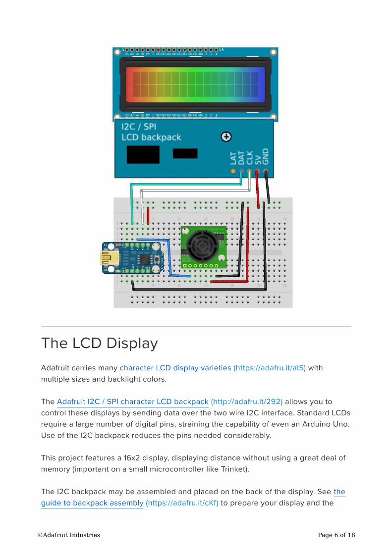
The LCD Display
Adafruit carries many character LCD display varieties (https://adafru.it/aIS) with
multiple sizes and backlight colors.
The Adafruit I2C / SPI character LCD backpack (http://adafru.it/292) allows you to
control these displays by sending data over the two wire I2C interface. Standard LCDs
require a large number of digital pins, straining the capability of even an Arduino Uno.
Use of the I2C backpack reduces the pins needed considerably.
This project features a 16x2 display, displaying distance without using a great deal of
memory (important on a small microcontroller like Trinket).
The I2C backpack may be assembled and placed on the back of the display. See the
guide to backpack assembly (https://adafru.it/cKf) to prepare your display and the
©Adafruit Industries Page 6 of 18
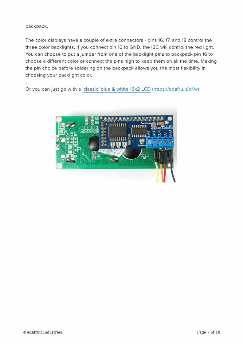
backpack.
The color displays have a couple of extra connectors - pins 16, 17, and 18 control the
three color backlights. If you connect pin 16 to GND, the I2C will control the red light.
You can choose to put a jumper from one of the backlight pins to backpack pin 16 to
choose a different color or connect the pins high to keep them on all the time. Making
the pin choice before soldering on the backpack allows you the most flexibility in
choosing your backlight color.
.
Or you can just go with a 'classic' blue & white 16x2 LCD (https://adafru.it/cKw)
©Adafruit Industries Page 7 of 18

Adding the Sensor
Once you have the display connected to the Trinket, you can expand the project in
many ways. One of the most popular is to add sensor(s) of some sort. The Adafruit
store has a wonderful selection to chose from (https://adafru.it/cKh).
The easiest place to add a sensor is to Trinket GPIO #1. GPIO pins #0 and #2 are used
for the display.
On the original ATtiny85-based Trinket, #3 and #4 are shared with the USB port.
Using #3 and #4 is perfectly fine, but you may have to disconnect the connections on
those pins when uploading software. The Trinket M0 doesn't have this restriction, by
the way.
©Adafruit Industries Page 8 of 18

Also, limiting a project to pins #0 to #2 gives you a similar pinout to the Adafruit Gem
ma M0 (https://adafru.it/ytb) wearable controller.
This project demonstrates using the Maxbotix family of ultrasonic proximity sensors.
These sensors are extremely flexible to interface via serial, analog, and pulse width
outputs. Linking in the SoftwareSerial library with the TinyLiquidCrystal exceeds the
memory available on the Trinket. The pulse output may be sensed on one digital pin
and works on Trinket GPIO #1 (the one shared with the red LED). This is the
connection used here. (We could also use the analog output, it could be connected to
the Trinket GPIO #3 or #4 but like we said, the original Trinket has these on the USB
interface too - so using these could require the connection be removed during USB
programming.)
A small stick of header, 7 pins long, was soldered to the sensor to facilitate
attachment to the breadboard.
See the wiring on the Fritzing diagram (first page) and the picture (second page). It is
fairly easy to connect Maxbotic sensors. You use only 3 of the 7 pins on the sensor for
sensing via the pulse width output:
Maxbotix +5 to Trinket 5V or 3V (the sensor takes a 2.5V to 5.5V supply with a
2mA typical current draw)
Maxbotix GND to Trinket GND
Sensor PW (Pulse Width) to Trinket GPIO #1
•
•
•
©Adafruit Industries Page 9 of 18

Arduino Code
The 5V Trinket was tested at 8 MHz. The Maxbotix LV Series can operate from 2.5 to
5.5 volts, most likely supporting Trinket 3V and Gemma. The LCD display is a 5 volt
device so it may require separate power if you keep it as part of your project.
To test the display, wire the DAT pin to Trinket GPIO #0, the CLK pin to Trinket GPIO
#2, 5V to the Trinket 5V or USB line and GND to GND.
Ensure your Arduino IDE has support added for Adafruit Trinket. For Arduino.cc IDE
version 1.6.7 and above, all you need to do is add the Adafruit AVR Boards package in
the Tools -> Board Managers section which provides Trinket support.
The display test program is a variation of the Hello World program. You need to install
two libraries for the I2C and LCD functions: the Wire library and Adafruit_LiquidCr
ystal library respectively. Unlike when Getting Started with Adafruit Trinket was
published, no modifications to the IDE are needed, only support added for the boards.
Much easier.
If this is your first time using Trinket, work through the guides first:
Adafruit Trinket M0 Guide (https://adafru.it/CcQ)
Adafruit Trinket Guide (https://adafru.it/CcS)
The Arduino code presented below works equally well on the Trinket M0 and
Mini Trinket 5v. If you have an M0 board, consider using the CircuitPython code
on the next page of this guide, no Arduino IDE required!
•
•
If you are using an Adafruit Trinket 5V 8 MHz be sure and select the Programmer
as USBtinyISP in the Arduino IDE under the Tools menu.
©Adafruit Industries Page 10 of 18

Software Libraries Used
To maximize the functionality of software on Trinket, new libraries need to be
installed. See the All About Arduino Libraries (https://adafru.it/aYM) tutorial for details
on how to download and install thee liquidcrystal library.
The Arduino internal Wire library for I2C communications
The Adafruit_LiquidCrystal (https://adafru.it/leO) library
No library is needed for the ultrasonic sensor.
// SPDX-FileCopyrightText: 2018 Mikey Sklar for Adafruit Industries
// SPDX-FileCopyrightText: 2018 Anne Barela for Adafruit Industries
//
// SPDX-License-Identifier: MIT
/*
Demonstration sketch for Adafruit LCD backpack
using MCP23008 I2C expander and Maxbotic LV-EZ1 Ultrasonic Sensor
(other pin compatible Maxbotix sensors should also work)
Tested with the 5 volt Trinket mini microcontroller at 8 MHz
The ultrasonic sensor and pin use should be Gemma and Trinket 3V compatible
This sketch reads the LV-EZ1 by pulse count and prints the distance to the LCD
The circuit:
* 5V to Arduino 5V pin, I2C Backpack 5V and EZ1 +5
* GND to Arduino GND pin, I2C Backpack GND and EZ1 GND
* Display I2C Backpack CLK to Trinket GPIO #2
* Display I2C backpack DAT to Trinket GPIO #0
* LV-EZ1 Ultrasonic Sensor PW pin to Trinket GPIO #1
Portions of code provided free use on http://playground.arduino.cc/Main/MaxSonar
by Bruce Allen and Bill Gentles
Version 2.0 Adds Arduino IDE 1.6.7 and greater Wire support
Anne Barela for Adafruit Industries
*/
// include the library code
#include <Adafruit_LiquidCrystal.h> // Tiny LiquidCrystal library using TinyWireM
#define EZ1pin 1 // Trinket GPIO #1
// Connect display via i2c, default address #0 (A0-A2 not jumpered)
Adafruit_LiquidCrystal lcd(0);
// These values are for calculating a mathematical median for a number of samples as
// suggested by Maxbotix instead of a mathematical average
int8_t arraysize = 9; // quantity of values to find the median (sample size). Needs to be an odd number
//declare an array to store the samples. not necessary to zero the array values
here, it just makes the code clearer
uint16_t rangevalue[] = { 0, 0, 0, 0, 0, 0, 0, 0, 0};uint16_t modE; // calculated median distance
void setup() { pinMode(EZ1pin, INPUT); // Sey ultrasonic sensor pin as input
lcd.begin(16, 2); // set up the LCD number of rows and columns:
•
•
©Adafruit Industries Page 11 of 18

lcd.setBacklight(HIGH); // Set backlight on (HIGH on, LOW off)
}
void loop() { int16_t pulse; // number of pulses from sensor int i=0;
while( i < arraysize ) {
pulse = pulseIn(EZ1pin, HIGH); // read in time for pin to transition rangevalue[i]=pulse/58; // pulses to centimeters (use 147 for inches) if( rangevalue[i] < 645 && rangevalue[i] >= 15 ) i++; // ensure no values out of range
delay(10); // wait between samples
}
isort(rangevalue,arraysize); // sort samples
modE = mode(rangevalue,arraysize); // get median
lcd.setCursor(0, 0); // write data to LCD display via I2C backpack
lcd.print("Range: "); // write to LCD
lcd.setCursor(7,0);
lcd.print(" ");
lcd.setCursor(7,0);
lcd.print(modE);
lcd.setCursor(11,0);
lcd.print("cm");
delay(500); // Read every half second
}
// Sorting function (Author: Bill Gentles, Nov. 12, 2010)
void isort(uint16_t *a, int8_t n){ for (int i = 1; i < n; ++i) { uint16_t j = a[i]; int k; for (k = i - 1; (k >= 0) && (j < a[k]); k--) { a[k + 1] = a[k]; }
a[k + 1] = j; }
}
// Mode function, returning the mode or median.
uint16_t mode(uint16_t *x,int n){ int i = 0; int count = 0; int maxCount = 0; uint16_t mode = 0; int bimodal; int prevCount = 0; while(i<(n-1)){ prevCount=count; count=0; while( x[i]==x[i+1] ) { count++; i++; }
if( count > prevCount & count > maxCount) { mode=x[i]; maxCount=count; bimodal=0; }
if( count == 0 ) { i++; }
if( count == maxCount ) { //If the dataset has 2 or more modes. bimodal=1; }
if( mode==0 || bimodal==1 ) { // Return the median if there is no mode.
©Adafruit Industries Page 12 of 18

mode=x[(n/2)]; }
return mode; }
}
What if I have no display?
Using the contrast potentiometer on the backpack (a small silver bump), turn the dial
with a small screwdriver. Change the contrast until you can read the text.
Saving Space
The above code compiles to 4,336 bytes of 5,310 available. This leaves over
900 bytes of code on an original Trinket if you wish to add additional functionality. On
a Trinket M0 you have a ton of space to spare. If you use decimal (floating point)
numbers, you will most likely exceed the space available. The Arduino IDE built-in
functions which calculate floating point math are somewhat large.
CircuitPython Code
Trinket M0 boards can run CircuitPython — a different approach to programming
compared to Arduino sketches. In fact, CircuitPython comes factory pre-loaded on
Trinket M0. If you’ve overwritten it with an Arduino sketch, or just want to learn the
basics of setting up and using CircuitPython, this is explained in the Adafruit (https://
adafru.it/zxF)Trinket M0 guide (https://adafru.it/zxF).
©Adafruit Industries Page 13 of 18

Below is CircuitPython code that works similarly (though not exactly the same) as the
Arduino sketch shown on a prior page. To use this, plug the Trinket M0 into USB…it
should show up on your computer as a small flash drive…then edit the file “code.py”
with your text editor of choice. Select and copy the code below and paste it into that
file, entirely replacing its contents (don’t mix it in with lingering bits of old code). When
you save the file, the code should start running almost immediately (if not, see notes
at the bottom of this page).
If Trinket M0 doesn’t show up as a drive, follow the Trinket M0 guide link above to
prepare the board for CircuitPython.
# SPDX-FileCopyrightText: 2018 Mikey Sklar for Adafruit Industries
#
# SPDX-License-Identifier: MIT
"""
This Code uses the:
* Adafruit LCD backpack using MCP23008 I2C expander
* Maxbotic LV-EZ1 Ultrasonic Sensor
Tested with the Trinket M0
The ultrasonic sensor and pin use should be Gemma M0 compatible
This sketch reads the LV-EZ1 by pulse count
Then prints the distance to the LCD and python console
The circuit:
* 5V to Trinket M0 USB or BAT pin, I2C Backpack 5V and EZ1 +5
* GND to Trinket M0 GND pin, I2C Backpack GND and EZ1 GND
* Display I2C Backpack SLK to Trinket GPIO #2
* Display I2C backpack SDA to Trinket GPIO #0
* LV-EZ1 Ultrasonic Sensor PW pin to Trinket GPIO #1
* Backlight can be hard wired by connecting LCD pin 16, 17 or 18 to GND
"""
import time
import adafruit_character_lcdimport boardimport busioimport pulseio
ez1pin = board.D1 # Trinket GPIO #1
# i2c LCD initialize bus and class
i2c = busio.I2C(board.SCL, board.SDA)cols = 16rows = 2lcd = adafruit_character_lcd.Character_LCD_I2C(i2c, cols, rows)
# calculated mode or median distance
mode_result = 0
# pulseio can store multiple pulses
# read in time for pin to transition
These directions are specific to the "M0” boards. The original Trinket with an 8-
bit AVR microcontroller doesn’t run CircuitPython…for those boards, use the
Arduino sketch on the “Arduino code” page of this guide.
©Adafruit Industries Page 14 of 18
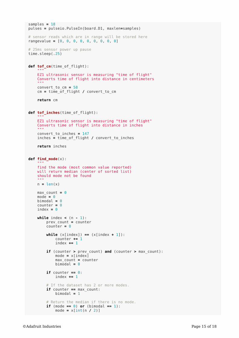
samples = 18pulses = pulseio.PulseIn(board.D1, maxlen=samples)
# sensor reads which are in range will be stored here
rangevalue = [0, 0, 0, 0, 0, 0, 0, 0, 0]
# 25ms sensor power up pause
time.sleep(.25)
def tof_cm(time_of_flight): """
EZ1 ultrasonic sensor is measuring "time of flight"
Converts time of flight into distance in centimeters
"""
convert_to_cm = 58 cm = time_of_flight / convert_to_cm
return cm
def tof_inches(time_of_flight): """
EZ1 ultrasonic sensor is measuring "time of flight"
Converts time of flight into distance in inches
"""
convert_to_inches = 147 inches = time_of_flight / convert_to_inches
return inches
def find_mode(x): """
find the mode (most common value reported)
will return median (center of sorted list)
should mode not be found
"""
n = len(x)
max_count = 0 mode = 0 bimodal = 0 counter = 0 index = 0
while index < (n - 1): prev_count = counter counter = 0
while (x[index]) == (x[index + 1]): counter += 1 index += 1
if (counter > prev_count) and (counter > max_count): mode = x[index] max_count = counter bimodal = 0
if counter == 0: index += 1
# If the dataset has 2 or more modes.
if counter == max_count: bimodal = 1
# Return the median if there is no mode.
if (mode == 0) or (bimodal == 1): mode = x[int(n / 2)]
©Adafruit Industries Page 15 of 18

return mode
while True:
# wait between samples
time.sleep(.5)
if len(pulses) == samples: j = 0 # rangevalue array counter
# only save the values within range
# range readings take 49mS
# pulse width is .88mS to 37.5mS
for i in range(0, samples): tof = pulses[i] # time of flight - PWM HIGH
if 880 < tof < 37500: if j < len(rangevalue): rangevalue[j] = tof_cm(tof) j += 1
# clear pulse samples
pulses.clear() # clear all values in pulses[]
# sort samples
rangevalue = sorted(rangevalue)
# returns mode or median
mode_result = int(find_mode(rangevalue))
# python console prints both centimeter and inches distance
cm2in = .393701 mode_result_in = mode_result * cm2in print(mode_result, "cm", "\t\t", int(mode_result_in), "in")
# result must be in char/string format for LCD printing
digit_string = str(mode_result)
lcd.clear()
lcd.message("Range: ") # write to LCD
lcd.message(" ")
lcd.message(digit_string)
lcd.message("cm")
time.sleep(2)
Installing Libraries:
The adafruit_character_lcd and adafruit_bus_device libraries must be installed for the
above code to run correctly. The latest version of the Adafruit CircuitPython Library
Bundle (https://adafru.it/Ayy) contains both libraries. You want to download the latest
stable mpy bundle which will have a filename like this:
adafruit-circuitpython-bundle-x.x.x-mpy-date.zip
©Adafruit Industries Page 16 of 18

The Trinket M0 has limited space, but so in this case we will be selective about which
files are copied over to the CIRCUITPY drive. A detailed explanation for installing
libraries is available (https://adafru.it/ABU).
Create these two directories and copy the following files from the unzip'd
CircuitPython Library Bundle to the CIRCUITPY drive to a new folder called 'lib'.
adafruit_character_lcd
./adafruit_character_lcd/character_lcd.mpy
./adafruit_character_lcd/__init__.py
./adafruit_character_lcd/character_lcd_rgb.mpy
./adafruit_character_lcd/mcp23008.mpy
adafruit_bus_device
./adafruit_bus_device/__init__.py
./adafruit_bus_device/i2c_device.mpy
Debugging and Going Further
Going Further
You can use any of the Maxbotix line of ultrasonic sensors to get differing distance
characteristics (be sure to change the code to reflect minimum and maximum distance
values).
If you're using a Trinket classic with ATtiny85, do conversion from centimeters to
inches or other calculations, you should use integer math (best to use an int16_t
integer size or larger for big numbers). This avoids linking in the big floating point
library for only a few calculations, possibly exceeding the memory available.
For projects using other sensor types, see the tutorials Trinket / Gemma Mini
Theramin (https://adafru.it/cKk) and Trinket Temperature & Humidity LCD Display (http
s://adafru.it/cL2).
•
◦
◦
◦
◦
•
◦
◦
©Adafruit Industries Page 17 of 18
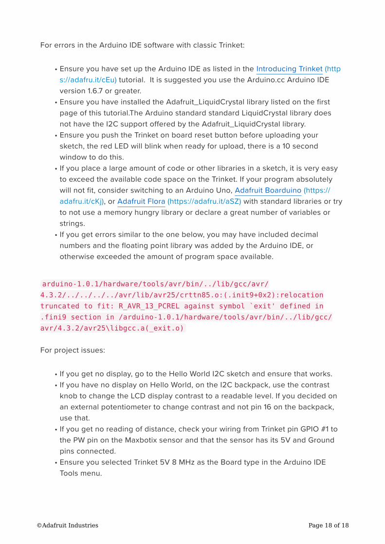
For errors in the Arduino IDE software with classic Trinket:
Ensure you have set up the Arduino IDE as listed in the Introducing Trinket (http
s://adafru.it/cEu) tutorial. It is suggested you use the Arduino.cc Arduino IDE
version 1.6.7 or greater.
Ensure you have installed the Adafruit_LiquidCrystal library listed on the first
page of this tutorial.The Arduino standard standard LiquidCrystal library does
not have the I2C support offered by the Adafruit_LiquidCrystal library.
Ensure you push the Trinket on board reset button before uploading your
sketch, the red LED will blink when ready for upload, there is a 10 second
window to do this.
If you place a large amount of code or other libraries in a sketch, it is very easy
to exceed the available code space on the Trinket. If your program absolutely
will not fit, consider switching to an Arduino Uno, Adafruit Boarduino (https://
adafru.it/cKj), or Adafruit Flora (https://adafru.it/aSZ) with standard libraries or try
to not use a memory hungry library or declare a great number of variables or
strings.
If you get errors similar to the one below, you may have included decimal
numbers and the floating point library was added by the Arduino IDE, or
otherwise exceeded the amount of program space available.
arduino-1.0.1/hardware/tools/avr/bin/../lib/gcc/avr/
4.3.2/../../../../avr/lib/avr25/crttn85.o:(.init9+0x2):relocation
truncated to fit: R_AVR_13_PCREL against symbol `exit' defined in
.fini9 section in /arduino-1.0.1/hardware/tools/avr/bin/../lib/gcc/
avr/4.3.2/avr25\libgcc.a(_exit.o)
For project issues:
If you get no display, go to the Hello World I2C sketch and ensure that works.
If you have no display on Hello World, on the I2C backpack, use the contrast
knob to change the LCD display contrast to a readable level. If you decided on
an external potentiometer to change contrast and not pin 16 on the backpack,
use that.
If you get no reading of distance, check your wiring from Trinket pin GPIO #1 to
the PW pin on the Maxbotix sensor and that the sensor has its 5V and Ground
pins connected.
Ensure you selected Trinket 5V 8 MHz as the Board type in the Arduino IDE
Tools menu.
•
•
•
•
•
•
•
•
•
©Adafruit Industries Page 18 of 18