Embed Size (px)
Citation preview

TRAINING MANUAL
Trimble® Field Link
Tablet®

Trimble Field Link for Structures Training Workbook
2014 © 2014 Trimble Buildings Confidential Page 0 of 105
Westminster Office
Trimble Navigation Limited
10368 Westmoor Drive
Westminster, Colorado 80021
(720) 887-6100
Copyright and Trademarks
© Copyright 2014 Trimble Buildings. All rights reserved. Trimble and the Globe &
Triangle logo are trademarks of Trimble Navigation Limited, registered in the United
States and in other countries. The names and logos of other companies mentioned
herein may be trademarks of their respective owners. This document is for
informational purposes only.
Microsoft, Windows, Internet Explorer and the Windows logo are registered
trademarks or trademarks of Microsoft Corporation in the United States and other
countries.
Adobe, the Adobe logo, Acrobat and the Acrobat logo are trademarks of Adobe
Systems Incorporated.
Release Notice
The topics within this manual are subject to change without written notice.
Companies, names, and data used in any examples are fictitious. Screenshots
included in the help topics may not be exactly as in the software application.
Monday, August 18, 2014. IW
Legend
The following symbols are used in this training.
Important
Indicates an important concept, step, or caution.
Tip
A shortcut or time-saving tip.
Note
Additional information or situation users may encounter.
Trimble Field Link for Structures Training Workbook
2014 © 2014 Trimble Buildings Confidential Page 1 of 105
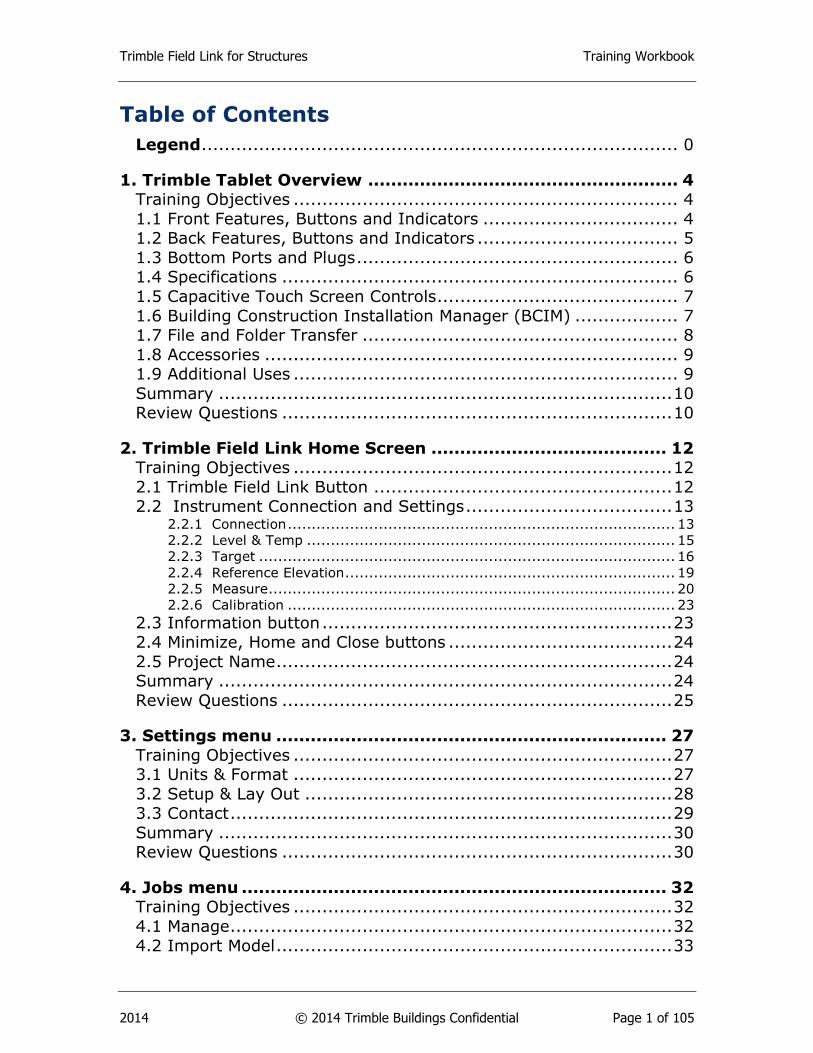
Table of Contents
Legend ................................................................................... 0
1. Trimble Tablet Overview ...................................................... 4
Training Objectives ................................................................... 4
1.1 Front Features, Buttons and Indicators .................................. 4
1.2 Back Features, Buttons and Indicators ................................... 5
1.3 Bottom Ports and Plugs ........................................................ 6
1.4 Specifications ..................................................................... 6
1.5 Capacitive Touch Screen Controls .......................................... 7
1.6 Building Construction Installation Manager (BCIM) .................. 7
1.7 File and Folder Transfer ....................................................... 8
1.8 Accessories ........................................................................ 9
1.9 Additional Uses ................................................................... 9
Summary ............................................................................... 10
Review Questions .................................................................... 10
2. Trimble Field Link Home Screen ......................................... 12
Training Objectives .................................................................. 12
2.1 Trimble Field Link Button .................................................... 12
2.2 Instrument Connection and Settings .................................... 13 2.2.1 Connection ................................................................................. 13 2.2.2 Level & Temp ............................................................................. 15 2.2.3 Target ....................................................................................... 16 2.2.4 Reference Elevation ..................................................................... 19 2.2.5 Measure ..................................................................................... 20 2.2.6 Calibration ................................................................................. 23
2.3 Information button ............................................................. 23
2.4 Minimize, Home and Close buttons ....................................... 24
2.5 Project Name ..................................................................... 24
Summary ............................................................................... 24
Review Questions .................................................................... 25
3. Settings menu .................................................................... 27
Training Objectives .................................................................. 27
3.1 Units & Format .................................................................. 27
3.2 Setup & Lay Out ................................................................ 28
3.3 Contact ............................................................................. 29
Summary ............................................................................... 30
Review Questions .................................................................... 30
4. Jobs menu .......................................................................... 32
Training Objectives .................................................................. 32
4.1 Manage ............................................................................. 32
4.2 Import Model ..................................................................... 33
Trimble Field Link for Structures Training Workbook
2014 © 2014 Trimble Buildings Confidential Page 2 of 105
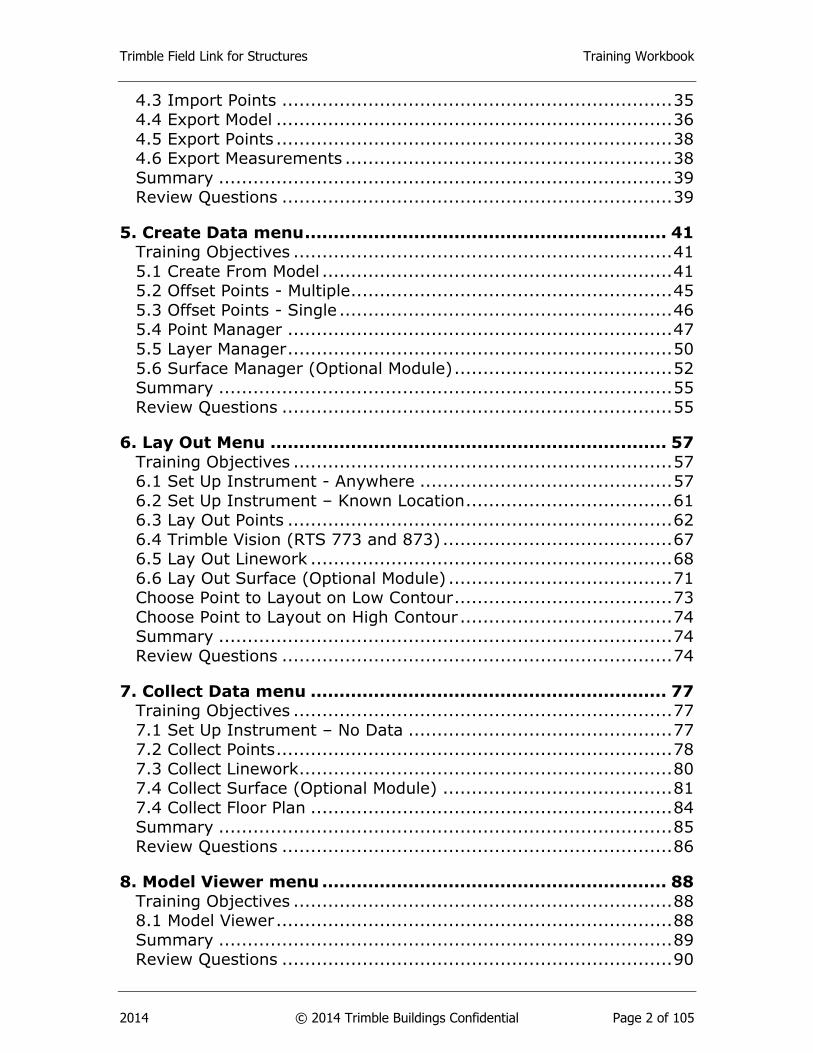
4.3 Import Points .................................................................... 35
4.4 Export Model ..................................................................... 36
4.5 Export Points ..................................................................... 38
4.6 Export Measurements ......................................................... 38
Summary ............................................................................... 39
Review Questions .................................................................... 39
5. Create Data menu ............................................................... 41
Training Objectives .................................................................. 41
5.1 Create From Model ............................................................. 41
5.2 Offset Points - Multiple ........................................................ 45
5.3 Offset Points - Single .......................................................... 46
5.4 Point Manager ................................................................... 47
5.5 Layer Manager ................................................................... 50
5.6 Surface Manager (Optional Module) ...................................... 52
Summary ............................................................................... 55
Review Questions .................................................................... 55
6. Lay Out Menu ..................................................................... 57
Training Objectives .................................................................. 57
6.1 Set Up Instrument - Anywhere ............................................ 57
6.2 Set Up Instrument – Known Location .................................... 61
6.3 Lay Out Points ................................................................... 62
6.4 Trimble Vision (RTS 773 and 873) ........................................ 67
6.5 Lay Out Linework ............................................................... 68
6.6 Lay Out Surface (Optional Module) ....................................... 71
Choose Point to Layout on Low Contour ...................................... 73
Choose Point to Layout on High Contour ..................................... 74
Summary ............................................................................... 74
Review Questions .................................................................... 74
7. Collect Data menu .............................................................. 77
Training Objectives .................................................................. 77
7.1 Set Up Instrument – No Data .............................................. 77
7.2 Collect Points ..................................................................... 78
7.3 Collect Linework ................................................................. 80
7.4 Collect Surface (Optional Module) ........................................ 81
7.4 Collect Floor Plan ............................................................... 84
Summary ............................................................................... 85
Review Questions .................................................................... 86
8. Model Viewer menu ............................................................ 88
Training Objectives .................................................................. 88
8.1 Model Viewer ..................................................................... 88
Summary ............................................................................... 89
Review Questions .................................................................... 90
Trimble Field Link for Structures Training Workbook
2014 © 2014 Trimble Buildings Confidential Page 3 of 105
9. Tools Menu ......................................................................... 91
Training Objectives .................................................................. 91
9.1 Compute Distance .............................................................. 91
9.2 Compute Angle .................................................................. 92
9.3 Compute Area & Volume ..................................................... 93
9.4 Unit Conversion - Length .................................................... 94
9.5 Unit Conversion - Area ........................................................ 95
9.6 Unit Conversion - Volume .................................................... 96
Summary ............................................................................... 96
Review Questions .................................................................... 96
10. Reports menu ................................................................... 98
Training Objectives .................................................................. 98
10.1 Daily Layout Summary ...................................................... 98
10.2 Layout Deviations ............................................................. 99
10.3 Field Report ................................................................... 100
10.4 Surface Report (Optional Module) ..................................... 101
Summary ............................................................................. 103
Review Questions .................................................................. 103
Trimble Field Link for Structures Training Workbook
2014 © 2014 Trimble Buildings Confidential Page 4 of 105
1. Trimble Tablet Overview
Training Objectives
Upon completion of the Trimble Tablet Overview, you will be able to:
Understand the various Features, Buttons, Indicators and Specifications
of the Trimble Field Link Tablet.
Use the Capacitive Touch functions to operate the Tablet.
Install Building Construction Installation Manager (BCIM) from the
Trimble website to manage the installation of Trimble Field Link for
Structures, software updates, firmware and other Trimble software.
Transfer files to and from the Trimble Field Link.
Know some of the common accessories and additional uses for the Trimble
Field Link Tablet.
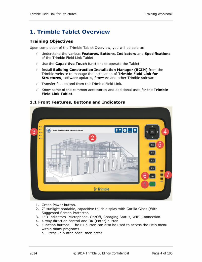
1.1 Front Features, Buttons and Indicators
1. Green Power button.
2. 7” sunlight readable, capacitive touch display with Gorilla Glass (With
Suggested Screen Protector.
3. LED Indicators- Microphone, On/Off, Charging Status, WIFI Connection.
4. 4-way direction control and OK (Enter) button.
5. Function buttons. The F1 button can also be used to access the Help menu
within many programs.
a. Press Fn button once, then press:
Trimble Field Link for Structures Training Workbook
2014 © 2014 Trimble Buildings Confidential Page 5 of 105
1. Arrow buttons up/down or left/right to increase or decrease the
screen back light.
2. F1 = Virtual Keyboard.
3. F2 = Internet Explorer
4. F3 = Switch Between Automatic or Manual screen back light.
b. Press Fn button twice, then press:
1. Arrow buttons up/down or left/right to increase or decrease the
volume settings.
2. F1 = Turn WIFI Off/On.
3. F2 = Turn Blue Tooth Off/On
4. F3 = Turn 3G Wireless Off/On.
c. Press Fn button three times, then press:
1. Arrow buttons up/down or left/right to move the cursor
2. F1 = Turn On the Tablet camera
3. F2 = Turn On the Trimble GPS Information
4. F3 = Open
6. Lock (Ctrl-Alt-Delete) button
7. Speaker
Tip
Use the Windows Mobility Center under All Programs/Accessories, to
access the Fn functions above including screen back lighting, volume,
battery settings, WIFI Off/On, and display options.
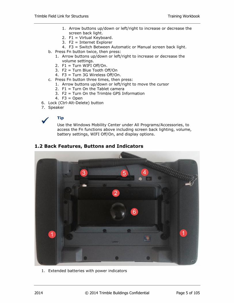
1.2 Back Features, Buttons and Indicators
1. Extended batteries with power indicators
Trimble Field Link for Structures Training Workbook
2014 © 2014 Trimble Buildings Confidential Page 6 of 105
a. Press the button on the inside face of each battery to show the
individual battery level with 1 – 4 green LED lights.
b. If additional batteries for the Tablet are purchased, you can use the
screw mounts to swap batteries one at a time while still in operation.
2. Integrated 2.4 GHz radio for Trimble Robotic Total Station connection.
3. Replaceable antennae for the 2.4 GHz radio.
4. Camera with flash.
5. Stylus holder and cord.
6. Range pole bracket and mount.
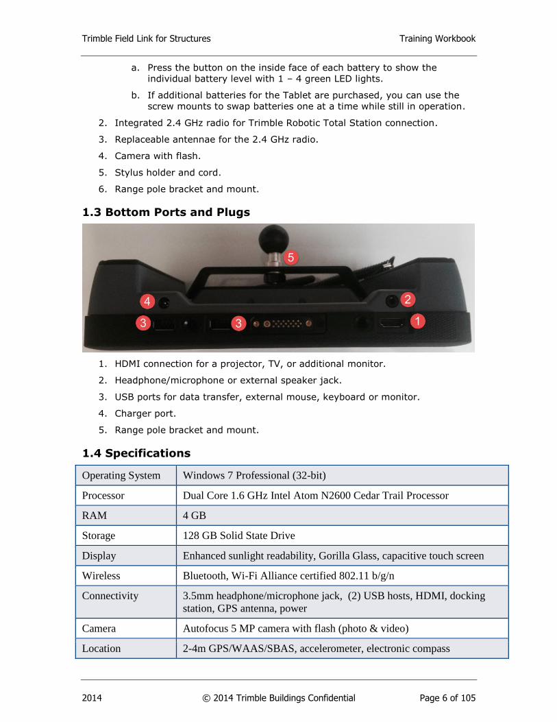
1.3 Bottom Ports and Plugs
1. HDMI connection for a projector, TV, or additional monitor.
2. Headphone/microphone or external speaker jack.
3. USB ports for data transfer, external mouse, keyboard or monitor.
4. Charger port.
5. Range pole bracket and mount.
1.4 Specifications
Operating System Windows 7 Professional (32-bit)
Processor Dual Core 1.6 GHz Intel Atom N2600 Cedar Trail Processor
RAM 4 GB
Storage 128 GB Solid State Drive
Display Enhanced sunlight readability, Gorilla Glass, capacitive touch screen
Wireless Bluetooth, Wi-Fi Alliance certified 802.11 b/g/n
Connectivity 3.5mm headphone/microphone jack, (2) USB hosts, HDMI, docking
station, GPS antenna, power
Camera Autofocus 5 MP camera with flash (photo & video)
Location 2-4m GPS/WAAS/SBAS, accelerometer, electronic compass
Trimble Field Link for Structures Training Workbook
2014 © 2014 Trimble Buildings Confidential Page 7 of 105
Battery 10 hours
Environmental IP65, Mil Std 106G
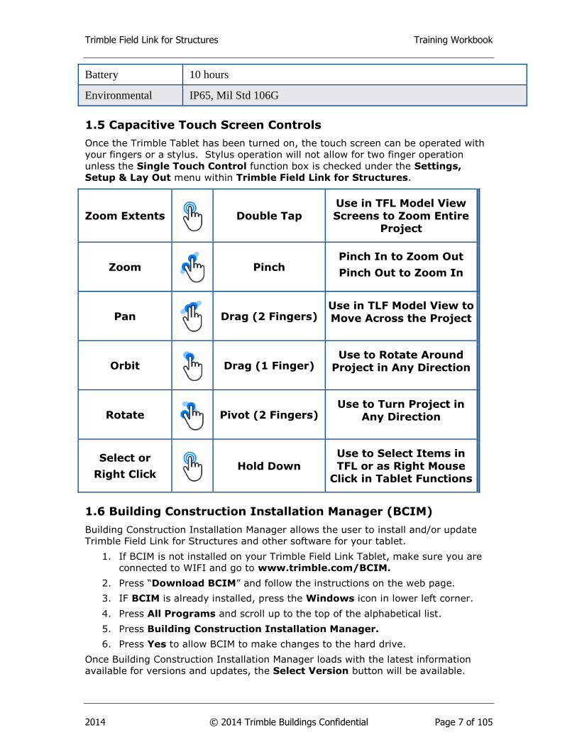
1.5 Capacitive Touch Screen Controls
Once the Trimble Tablet has been turned on, the touch screen can be operated with
your fingers or a stylus. Stylus operation will not allow for two finger operation
unless the Single Touch Control function box is checked under the Settings,
Setup & Lay Out menu within Trimble Field Link for Structures.
1.6 Building Construction Installation Manager (BCIM)
Building Construction Installation Manager allows the user to install and/or update
Trimble Field Link for Structures and other software for your tablet.
1. If BCIM is not installed on your Trimble Field Link Tablet, make sure you are
connected to WIFI and go to www.trimble.com/BCIM.
2. Press “Download BCIM” and follow the instructions on the web page.
3. IF BCIM is already installed, press the Windows icon in lower left corner.
4. Press All Programs and scroll up to the top of the alphabetical list.
5. Press Building Construction Installation Manager.
6. Press Yes to allow BCIM to make changes to the hard drive.
Once Building Construction Installation Manager loads with the latest information
available for versions and updates, the Select Version button will be available.
Zoom Extents
Double Tap
Use in TFL Model View
Screens to Zoom Entire Project
Zoom
Pinch Pinch In to Zoom Out
Pinch Out to Zoom In
Pan
Drag (2 Fingers) Use in TLF Model View to
Move Across the Project
Orbit
Drag (1 Finger) Use to Rotate Around
Project in Any Direction
Rotate
Pivot (2 Fingers) Use to Turn Project in
Any Direction
Select or
Right Click
Hold Down
Use to Select Items in
TFL or as Right Mouse Click in Tablet Functions
Trimble Field Link for Structures Training Workbook
2014 © 2014 Trimble Buildings Confidential Page 8 of 105
There will also be additional check boxes with descriptions of software available for
download. BCIM will automatically default to the latest version of Trimble Field Link
for Structures.
1. Press the Select Version button to load previous versions of Trimble Field
Link, or check to make sure the latest update has been selected.
2. Check the first box to install Latest Version of Trimble Field Link for
Structures
3. Check the box to install Trimble Field Link Job File Converter. This
program will convert .cnx files to .tfl files.
4. Check the boxes next to the CAD and BIM to install Tekla BIMSight,
SketchUp Pro or SketchUp Make software on the Tablet.
5. Check the boxes next to Additional Applications to install the latest
versions of firmware for the Robotic Total Stations (RTS).
6. Install optional modules such as Surfaces or Floor Plan
7. Press the Release Notes button to review updates before installation.
8. Press the Register button and fill out the information page to sign up for
notification of updates.
9. Press the Install button and follow all prompts.
Important
If you Register your product in BCIM and are under a current warranty
or maintenance agreement, you will get automatic notifications of
Trimble Field Link software updates.
Tip
Make sure to set your Windows updates settings for manual installation.
Automatic installation may cause long periods of time where you cannot
demonstrate or use the Trimble Tablet.
1.7 File and Folder Transfer
This section will cover the Trimble Field Link folder locations and structure for job
management. We will also cover the many ways to get files to and from the Trimble
Field Link Tablet.
1. Press the Windows Explorer button to access the computer drives and
folders.
2. Under the Libraries folder, press the Documents tab.
3. Press the Trimble Field Link folder.
4. Within the Trimble Field Link folder, the Jobs folder will be automatically
created. This will be the location to store job files or create new job folders to
help separate projects. Trimble Field Link will automatically create Exports,
Images, and Reports folders when you create one of these items within the
Trimble Field Link for Structures software.
5. To create a shortcut on the desktop, press once and highlight the Trimble
Field Link folder, hold down on the folder or right click using a mouse to
bring up the menu of folder options, then press the Send to and press
Desktop (create shortcut).
Trimble Field Link for Structures Training Workbook
2014 © 2014 Trimble Buildings Confidential Page 9 of 105
6. To transfer files, the Trimble Field Link Tablet has many options including USB
memory sticks, Bluetooth connection to another computer, or utilize the WIFI
connection for emails, FTP type transfer sites, or synchronized folders such as
Trimble Connected Community. To copy a file or folder, press once and
highlight the file or folder, hold down on the file or folder (or right click using
a mouse) to bring up the menu of folder options, then press Copy.
7. Navigate to the desired location and hold down or right click using a mouse in
the white space to bring up the menu of folder options, then press Paste.
8. The file or folder should appear in the new location.
Tip
Establish a mobile WIFI connection using your Hot Spot from your
mobile device. The mobile WIFI connection will allow you to send or
receive information remotely in the field such as updated models,
drawings, point files, reports, or as-built information through email or
synchronized cloud based storage systems.
1.8 Accessories
The Trimble Tablet is a fully functional Windows 7 computer with specialized housing
for field layout applications. The tablet can be utilized with a mouse, external
monitor, or other accessories which will enhance the use of your Trimble Field Link
Tablet either in the field or in the office. Below are a few of the common accessories
available through your authorized Trimble distributor.
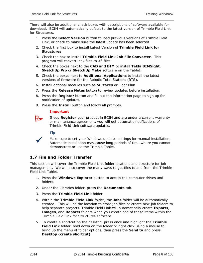
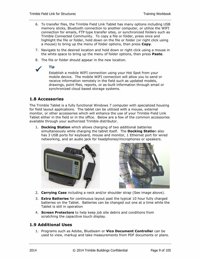
1. Docking Station which allows charging of two additional batteries
simultaneously while charging the tablet itself. The Docking Station also
has 3 USB ports for keyboard, mouse and monitor, 1 Ethernet port for wired
networking, and an audio jack for headphones/microphones or speakers.
2. Carrying Case including a neck and/or shoulder strap (See image above).
3. Extra Batteries for continuous layout past the typical 10 hour fully charged
batteries on the Tablet. Batteries can be changed out one at a time while the
Tablet is still in operation
4. Screen Protectors to help keep job site debris and conditions from
scratching the capacitive touch display.
1.9 Additional Uses
1. Programs such as Adobe, Bluebeam or Vico Document Controller can be
used to view, markup and take measurements from PDF documents or plans.

Trimble Field Link for Structures Training Workbook
2014 © 2014 Trimble Buildings Confidential Page 10 of 105
2. Use Trimble Connected Community (TCC) at www.myconnectedsite.com
for project data storage and the TCC Explorer to automatically synchronize
specific project folders to your tablet automatically with WIFI connection or
overnight at the office.
3. SketchUp is a 3D modeling program for everyone. You can quickly draw line
work, model difficult 3D shapes, export or import 3D model files, along with
many other applications. Visit www.SketchUp.com for more information.
4. Download Tekla BIMSight at www.TeklaBIMSight.com for model
coordination, conflict detection, make notes or even add documents or images
to the as-built model.
Summary
After review of this Trimble Tablet Overview, you should now understand how to:
Access the various Features, Buttons, Indicators and know the
Specifications of the Trimble Field Link Tablet.
Use the Capacitive Touch functions to operate the Tablet.
Install Building Construction Installation Manager (BCIM) from the
Trimble website to manage the installation of Trimble Field Link for
Structures, software updates, firmware and other Trimble software.
Transfer files to and from the Trimble Field Link.
Utilize some of the common accessories and additional uses for the Trimble
Field Link Tablet.
Review Questions
1. Pressing the Function Fn button once, twice or three times along with the F1,
F2 or F3 button will allow modification of which of the following functions?
a. Turn WIFI Off or On
b. Increase or decrease the screen back light.
c. Increase or decrease the volume settings.
d. All of the above.
2. Which of the following accessories can be plugged into the USB or HDMI ports
on the bottom of the Trimble Tablet or Docking Station?
a. External Mouse.
b. External Keyboard.
c. Additional Monitor.
d. All of the above.
3. The Trimble Tablet is a fully functional Windows 7 computer with 128 GB
memory and 10 hours of battery life.
a. True
b. False
4. All but which one of the following methods can be used to transfer files and
folders to or from the Trimble Tablet.?
Trimble Field Link for Structures Training Workbook
2014 © 2014 Trimble Buildings Confidential Page 11 of 105
a. USB memory stick.
b. Crystal Ball Reports.
c. WIFI Connection to Email, FTP Sites or Cloud Based Storage Systems.
d. Bluetooth Connection.
5. BCIM (Building Construction Installation Manger) should be utilized to access
the latest version of which items?
a. Latest or previous versions of Trimble Field Link for Structures.
b. Latest firmware for RTS (Robotic Total Stations).
c. Other Trimble software such as SketchUp or Tekla BIMSight.
d. Trimble Field Link Job File Converter
e. All of the Above

Trimble Field Link for Structures Training Workbook
2014 © 2014 Trimble Buildings Confidential Page 12 of 105
2. Trimble Field Link Home Screen
Training Objectives
Upon completion of this Home Screen module, you will be able to:
Utilize the Home button to Navigate within Trimble Field Link for Structures.
Open the Instrument Connection and Settings menu and perform the
various functions within this menu.
Connect to the instrument and see the RTS battery, level and service status.
Select different prisms and operating modes.
Aim, move and search for prisms with the RTS.
Make reference elevation shots.
Take quick reference measurements from the instrument.
Calibrate the instrument in the field for axis and tracking corrections.
Find the Serial Number and Version of Trimble Field Link for Structures
installed on the tablet using the Information button.
2.1 Trimble Field Link Button
Pressing the Home button in the upper left corner of the Home Screen will show or
hide all of the various main menu buttons. The Home button is the main navigation
method within Trimble Field Link for Structures and can be pressed while operating
the various menus to select a different operation.
Trimble Field Link for Structures Training Workbook
2014 © 2014 Trimble Buildings Confidential Page 13 of 105
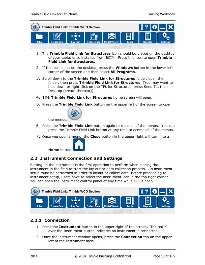
1. The Trimble Field Link for Structures icon should be placed on the desktop
of your tablet once installed from BCIM. Press this icon to open Trimble
Field Link for Structures.
2. If the icon is not on the desktop, press the Windows button in the lower left
corner of the screen and then select All Programs.
3. Scroll down to the Trimble Field Link for Structures folder, open the
folder, then press Trimble Field Link for Structures. (You may want to
hold down or right click on the TFL for Structures, press Send To, then
Desktop (create shortcut)).
4. The Trimble Field Link for Structures home screen will open.
5. Press the Trimble Field Link button on the upper left of the screen to open
the menus.
6. Press the Trimble Field Link button again to close all of the menus. You can
press the Trimble Field Link button at any time to access all of the menus.
7. Once you open a menu, the Close button in the upper right will turn into a
Home button.
2.2 Instrument Connection and Settings
Setting up the instrument is the first operation to perform when placing the
instrument in the field to start the lay out or data collection process. An instrument
setup must be performed in order to layout or collect data. Before proceeding to
instrument setup, users have to select the instrument icon in the top right corner.
You can open the instrument control panel at any time while TFL is open.
2.2.1 Connection
1. Press the Instrument button in the upper right of the screen. The red X
over the Instrument button indicates no instrument is connected.
2. Once the instrument window opens, press the Connection tab on the upper
left of the Instrument menu.
Trimble Field Link for Structures Training Workbook
2014 © 2014 Trimble Buildings Confidential Page 14 of 105
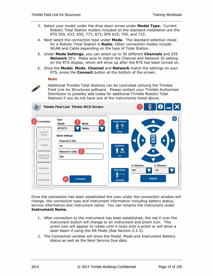
3. Select your model under the drop down arrow under Model Type. Current
Robotic Total Station models included on the standard installation are the
RTS 555, 633, 655, 773, 873, SPS 610, 700, and 710.
4. Next select the connection type under Mode. The standard selection mode
for a Robotic Total Station is Radio. Other connection modes include
WLAN and Cable depending on the type of Total Station.
5. Under Mode Settings, you can select up to 30 different Channels and 255
Network ID’s. Make sure to match the Channel and Network ID setting
on the RTS display, which will show up after the RTS has been turned on.
6. Once the Model, Mode, Channel and Network match the settings on your
RTS, press the Connect button at the bottom of the screen.
Note
Additional Trimble Total Stations can be controlled utilizing the Trimble
Field Link for Structures software. Please contact your Trimble Authorized
Distributor to possibly add codes for additional Trimble Robotic Total
Stations if you do not have one of the instruments listed above.
Once the connection has been established the view under the connection window will
change. the connection type and instrument information including battery status,
service information and instrument name. You can rename the instrument under
Instrument Name.
1. After connection to the instrument has been established, the red X over the
instrument button will change to an instrument and prism icon. This
prism icon will appear to rotate until it locks onto a prism or will show a
laser beam if using the DR Mode (See Section 2.2.3).
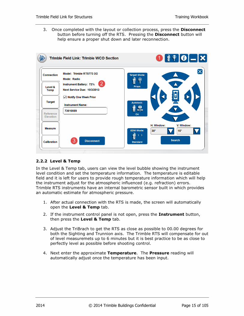
2. The Connection window will show the Model, Mode and Instrument Battery
status as well as the Next Service Due date.
Trimble Field Link for Structures Training Workbook
2014 © 2014 Trimble Buildings Confidential Page 15 of 105
3. Once completed with the layout or collection process, press the Disconnect
button before turning off the RTS. Pressing the Disconnect button will
help ensure a proper shut down and later reconnection.
2.2.2 Level & Temp
In the Level & Temp tab, users can view the level bubble showing the instrument
level condition and set the temperature information. The temperature is editable
field and it is left for users to provide rough temperature information which will help
the instrument adjust for the atmospheric influenced (e.g. refraction) errors.
Trimble RTS instruments have an internal barometric sensor built in which provides
an automatic estimate for atmospheric pressure.
1. After actual connection with the RTS is made, the screen will automatically
open the Level & Temp tab.
2. If the instrument control panel is not open, press the Instrument button,
then press the Level & Temp tab.
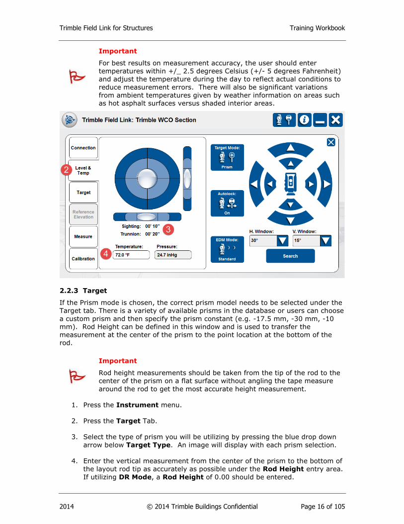
3. Adjust the TriBrach to get the RTS as close as possible to 00.00 degrees for
both the Sighting and Trunnion axis. The Trimble RTS will compensate for out
of level measuremets up to 6 minutes but it is best practice to be as close to
perfectly level as possible before shooting control.
4. Next enter the approximate Temperature. The Pressure reading will
automatically adjust once the temperature has been input.
Trimble Field Link for Structures Training Workbook
2014 © 2014 Trimble Buildings Confidential Page 16 of 105
Important
For best results on measurement accuracy, the user should enter
temperatures within +/_ 2.5 degrees Celsius (+/- 5 degrees Fahrenheit)
and adjust the temperature during the day to reflect actual conditions to
reduce measurement errors. There will also be significant variations
from ambient temperatures given by weather information on areas such
as hot asphalt surfaces versus shaded interior areas.
2.2.3 Target
If the Prism mode is chosen, the correct prism model needs to be selected under the
Target tab. There is a variety of available prisms in the database or users can choose
a custom prism and then specify the prism constant (e.g. -17.5 mm, -30 mm, -10
mm). Rod Height can be defined in this window and is used to transfer the
measurement at the center of the prism to the point location at the bottom of the
rod.
Important
Rod height measurements should be taken from the tip of the rod to the
center of the prism on a flat surface without angling the tape measure
around the rod to get the most accurate height measurement.
1. Press the Instrument menu.
2. Press the Target Tab.
3. Select the type of prism you will be utilizing by pressing the blue drop down
arrow below Target Type. An image will display with each prism selection.
4. Enter the vertical measurement from the center of the prism to the bottom of
the layout rod tip as accurately as possible under the Rod Height entry area.
If utilizing DR Mode, a Rod Height of 0.00 should be entered.
Trimble Field Link for Structures Training Workbook
2014 © 2014 Trimble Buildings Confidential Page 17 of 105
5. If the MT1000 prism is selected, select the Mode by using the blue drop down
arrow to select either Active or Passive. Active Mode will look for a prism
ID whereas Passive Mode will only look for a reflective prism.
6. If Active Mode has been selected for the MT1000, turn on an ID number on
the active prism (the LED lights will light when the MT1000 is turned on),
then use the blue drop down arrow to select the matching ID under RMT ID.
7. Utilize the instrument control arrows at the right to move the RTS in the
direction of the prism. The four interior arrows will move the RTS in fine
mode while the four outside arrows will move the RTS in fast mode.
Tip
With the Instrument Control Panel open, you can also use the four-way
direction controls on the far upper right of the Tablet to control the RTS.
8. To ensure proper set up of the target information or if your RTS unlocks from
the prism, you can utilize the Search function. The user can set the search
window to look for the prism in 15, 30 or 60 degree windows both vertically
and/or horizontally by pressing the blue drop down arrow under H. Window
and V. Window.
9. Press the Search button.
10. Once the RTS has locked onto the target, the Tablet will verbally announce
“Target Locked”, show the prism icon in the upper right hand instrument
control button as solid, and will end the search. The Tablet will give an error
message if no target can be found or announce “No Target” if visual contact is
lost and the prism icon will be rotating.
Tip
The user may also utilize Trimble Vision to lock onto the prism or DR
target. See Section 6.3 for information on Trimble Vision and
Dynamic Joystick. If the instrument is not equipped with Trimble
Vision, using the Track Light as noted below will help with the search
function.

Trimble Field Link for Structures Training Workbook
2014 © 2014 Trimble Buildings Confidential Page 18 of 105
2.2.3.1 Target Mode
The Target Mode can be toggled between Prism and DR by
pressing the Target Mode button. DR stands for Direct Reflex, which utilizes a visible
laser beam to measure directly to many surfaces without utilizing a reflective target.
Important
DR (Direct Reflex) Mode can only be utilized on surfaces which will
reflect the laser back to the RTS head unit. Shiny surfaces such as
highly polished concrete or stainless steel may bounce the laser away
from the RTS and not allow a measurement. Dark or very rough
surfaces such as asphalt, black paint, or carpet may absorb the laser
light and also not allow a measurement.
2.2.3.2 Autolock
When the Prism mode is used, the Autolock function should be on. This
will enable automatic prism tracking across the project site. Pressing the Autolock
button will toggle between On and Off.
2.2.3.3 Track Light
The RTS 773 and 873 are equipped with Trimble Vision allowing the user to view
through the instrument to help align with the prisms. The RTS 555, 633, 655 do not
have Trimble Vision and are therefore equipped with a Track Light to help with
alignment. The Track Light button will toggle between On and Off to operate red
Trimble Field Link for Structures Training Workbook
2014 © 2014 Trimble Buildings Confidential Page 19 of 105
and/or green LED lights on the instrument indicating the direction of the scope. As
the user is facing the instrument behind the prism, they will see quickly flashing
green LED lights if the instrument is locked onto the prism. The lights will flash
slowly green if the instrument is to the left or NOT locked onto the prism. The user
will see red flashing LED lights if the instrument is pointed to the right of the prism.
2.2.3.4 EDM Mode
EDM Mode allows users to toggle between Tracking (single
measurement) and Standard (average of multiple measurements). If Standard
mode is selected, the RTS will continue in Tracking mode until a point is shot, at
which time it will revert to the Standard mode and take an average of multiple
shots.
2.2.4 Reference Elevation
When laying out points in a construction environment, a reference elevation can be
applied for every instrument setup (See Settings Menu – Setup and Lay Out to
turn this selection off or on). In scenarios where the user is only concerned with the
horizontal axes, reference elevations may appear to be a trivial process; however it
is still recommended to ensure correct instrument vertical orientation and maintain a
consistent workflow from setup to setup. You can also shoot a reference elevation or
benchmark at any time after the Instrument Set Up has been performed.
1. The instrument set up within a job must be complete before the Reference
Elevation tab can utilized. Once you have shot your control points and the
instrument has calculated its position on the project, you can utilize the
Reference Elevation function. See Section 3.2 Settings, Setup & Lay Out to
automatically open the Reference Elevation After Instrument Set Up.
2. Press the Instrument menu.
3. Press the Reference Elevation Tab.
4. Under Elevation, enter the height of the reference elevation.
5. Place the prism and rod at the reference elevation making sure the rod is
directly plumb and vertical or position the DR laser light on your elevation,
then press the Measure button.
6. The Use Reference Elevation box will automatically be checked upon
measurement. Uncheck this box if you do not want to use the elevation for
future lay out or collection of data.
Trimble Field Link for Structures Training Workbook
2014 © 2014 Trimble Buildings Confidential Page 20 of 105
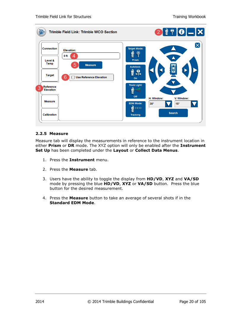
2.2.5 Measure
Measure tab will display the measurements in reference to the instrument location in
either Prism or DR mode. The XYZ option will only be enabled after the Instrument
Set Up has been completed under the Layout or Collect Data Menus.
1. Press the Instrument menu.
2. Press the Measure tab.
3. Users have the ability to toggle the display from HD/VD, XYZ and VA/SD
mode by pressing the blue HD/VD, XYZ or VA/SD button. Press the blue
button for the desired measurement.
4. Press the Measure button to take an average of several shots if in the
Standard EDM Mode.

Trimble Field Link for Structures Training Workbook
2014 © 2014 Trimble Buildings Confidential Page 21 of 105
HD = Horizontal Distance, VD = Vertical Distance, SD = Slope Distance, HA =
Horizontal Angle from 0 – 360* around the instrument.
VA = Vertical Angle based upon 90* = True Horizontal from the RTS, 0* = Straight
Down, 180* = Straight Up

Trimble Field Link for Structures Training Workbook
2014 © 2014 Trimble Buildings Confidential Page 22 of 105
Trimble Field Link for Structures Training Workbook
2014 © 2014 Trimble Buildings Confidential Page 23 of 105
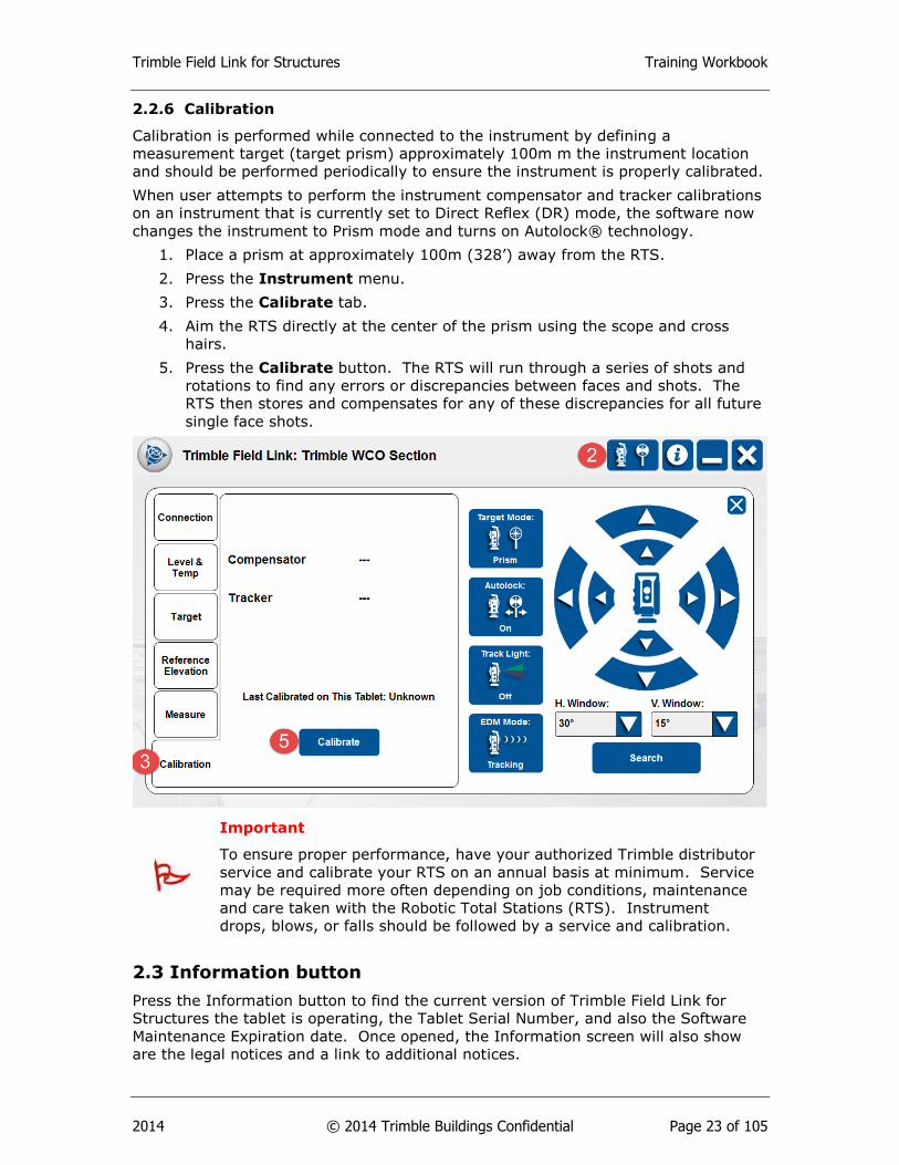
2.2.6 Calibration
Calibration is performed while connected to the instrument by defining a
measurement target (target prism) approximately 100m m the instrument location
and should be performed periodically to ensure the instrument is properly calibrated.
When user attempts to perform the instrument compensator and tracker calibrations
on an instrument that is currently set to Direct Reflex (DR) mode, the software now
changes the instrument to Prism mode and turns on Autolock® technology.
1. Place a prism at approximately 100m (328’) away from the RTS.
2. Press the Instrument menu.
3. Press the Calibrate tab.
4. Aim the RTS directly at the center of the prism using the scope and cross
hairs.
5. Press the Calibrate button. The RTS will run through a series of shots and
rotations to find any errors or discrepancies between faces and shots. The
RTS then stores and compensates for any of these discrepancies for all future
single face shots.
Important
To ensure proper performance, have your authorized Trimble distributor
service and calibrate your RTS on an annual basis at minimum. Service
may be required more often depending on job conditions, maintenance
and care taken with the Robotic Total Stations (RTS). Instrument
drops, blows, or falls should be followed by a service and calibration.
2.3 Information button
Press the Information button to find the current version of Trimble Field Link for
Structures the tablet is operating, the Tablet Serial Number, and also the Software
Maintenance Expiration date. Once opened, the Information screen will also show
are the legal notices and a link to additional notices.

Trimble Field Link for Structures Training Workbook
2014 © 2014 Trimble Buildings Confidential Page 24 of 105
1. Press the Information button in the upper right corner of the screen.
2. The Version will be visible towards the top of the screen.
3. The Tablet Serial Number will be towards the bottom of the screen, just above
the Software Maintenance Expiration date.
4. The Software Maintenance Expiration date will be at the bottom of the screen.
Important
The version, serial number and maintenance expiration are important
information to have available when calling for support. Keep your
software maintenance up to date through your local Trimble distributor.
2.4 Minimize, Home and Close buttons
Use the X button to close Trimble Field Link for Structures. This button will also
appear as a Home button to close out any various menus you are operating and
return to the Home screen. Make sure to disconnect from your instrument before
closing Trimble Field Link for Structures. Use the minimize button in the upper right
corner to access Windows 7 functions without shutting down Trimble Field Link for
Structures.
2.5 Project Name
The currently open project name will appear between the Home and Instrument
Connection buttons next to Trimble Field Link: New Job. Trimble Field Link will
automatically open the last used job on start up.
Summary
After review of this Home Screen module, you should now understand how to:
Utilize the Home button to Navigate within Trimble Field Link for Structures.
Trimble Field Link for Structures Training Workbook
2014 © 2014 Trimble Buildings Confidential Page 25 of 105
Open the Instrument Connection and Settings menu and perform the
various functions within this menu.
Quickly know if the instrument is connected to the Tablet and/or if the RTS is
locked onto the prism or in DR Mode.
Connect to the instrument and see the RTS battery, level and service status.
Select different prisms and operating modes.
Aim, move and search for prisms with the RTS.
Make reference elevation shots.
Take quick reference measurements from the instrument.
Calibrate the instrument in the field for axis and tracking corrections.
Find the Serial Number and Version of Trimble Field Link for Structures.
installed on the tablet using the Information button.
Review Questions
1. The Trimble Field Link button can be pressed at any time to access various
menus and functions.
a. True.
b. False.
2. You can press the Instrument and Connections button at any time to access
which of the following?
a. Instrument Battery Status.
b. Level of the Instrument and Temperature Setting.
c. Set the Prism type, Rod Height or Instrument Modes.
d. Make Reference Elevation shots or quick measurements.
e. All of the above.
3. The ambient temperature needs to be input by the user +/- 5 degrees and
adjusted during the day as temperatures fluctuate.
a. True
b. False
4. Calibration should be performed:
a. On an annual basis by an authorized Trimble distributor.
b. After drops, blows or falls by an authorized Trimble distributor.
c. Monthly in the field using the Calibration menu.
d. All of the above
5. Where should the user go to find the currently installed version of Trimble
Field Link for Structures and the Tablet Serial Number?
a. Information button
b. Instrument and Connections button.

Trimble Field Link for Structures Training Workbook
2014 © 2014 Trimble Buildings Confidential Page 26 of 105
c. Trimble Field Link button.
d. The Home button.
Trimble Field Link for Structures Training Workbook
2014 © 2014 Trimble Buildings Confidential Page 27 of 105
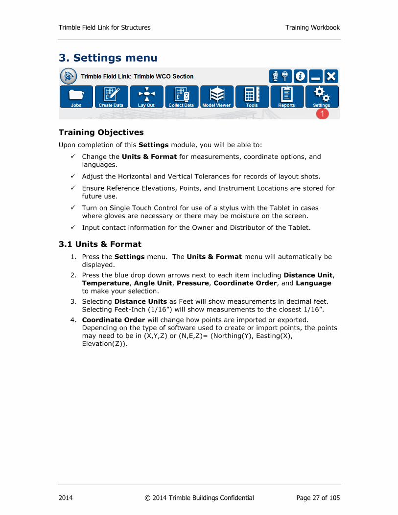
3. Settings menu
Training Objectives
Upon completion of this Settings module, you will be able to:
Change the Units & Format for measurements, coordinate options, and
languages.
Adjust the Horizontal and Vertical Tolerances for records of layout shots.
Ensure Reference Elevations, Points, and Instrument Locations are stored for
future use.
Turn on Single Touch Control for use of a stylus with the Tablet in cases
where gloves are necessary or there may be moisture on the screen.
Input contact information for the Owner and Distributor of the Tablet.
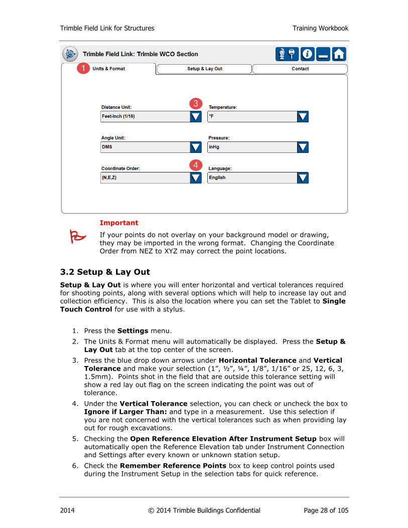
3.1 Units & Format
1. Press the Settings menu. The Units & Format menu will automatically be
displayed.
2. Press the blue drop down arrows next to each item including Distance Unit,
Temperature, Angle Unit, Pressure, Coordinate Order, and Language
to make your selection.
3. Selecting Distance Units as Feet will show measurements in decimal feet.
Selecting Feet-Inch (1/16”) will show measurements to the closest 1/16”.
4. Coordinate Order will change how points are imported or exported.
Depending on the type of software used to create or import points, the points
may need to be in (X,Y,Z) or (N,E,Z)= (Northing(Y), Easting(X),
Elevation(Z)).
Trimble Field Link for Structures Training Workbook
2014 © 2014 Trimble Buildings Confidential Page 28 of 105
Important
If your points do not overlay on your background model or drawing,
they may be imported in the wrong format. Changing the Coordinate
Order from NEZ to XYZ may correct the point locations.
3.2 Setup & Lay Out
Setup & Lay Out is where you will enter horizontal and vertical tolerances required
for shooting points, along with several options which will help to increase lay out and
collection efficiency. This is also the location where you can set the Tablet to Single
Touch Control for use with a stylus.
1. Press the Settings menu.
2. The Units & Format menu will automatically be displayed. Press the Setup &
Lay Out tab at the top center of the screen.
3. Press the blue drop down arrows under Horizontal Tolerance and Vertical
Tolerance and make your selection (1”, ½”, ¼”, 1/8”, 1/16” or 25, 12, 6, 3,
1.5mm). Points shot in the field that are outside this tolerance setting will
show a red lay out flag on the screen indicating the point was out of
tolerance.
4. Under the Vertical Tolerance selection, you can check or uncheck the box to
Ignore if Larger Than: and type in a measurement. Use this selection if
you are not concerned with the vertical tolerances such as when providing lay
out for rough excavations.
5. Checking the Open Reference Elevation After Instrument Setup box will
automatically open the Reference Elevation tab under Instrument Connection
and Settings after every known or unknown station setup.
6. Check the Remember Reference Points box to keep control points used
during the Instrument Setup in the selection tabs for quick reference.

Trimble Field Link for Structures Training Workbook
2014 © 2014 Trimble Buildings Confidential Page 29 of 105
7. Check the Store Instrument Location After Instrument Setup box to
create a point each time the instrument is setup in an unknown location.
8. Check the Level Telescope After Disabling Visual Layout box to
9. Check the Single Touch Control box to switch to stylus operation of the
Tablet in lieu of capacitive touch controls. Setting the Single Touch Control
will require Trimble Field Link for Structures to shut down and restart.
10. Press the Clear Layout Flags button to clear in or out of tolerance flags for
points already laid out within the open job.
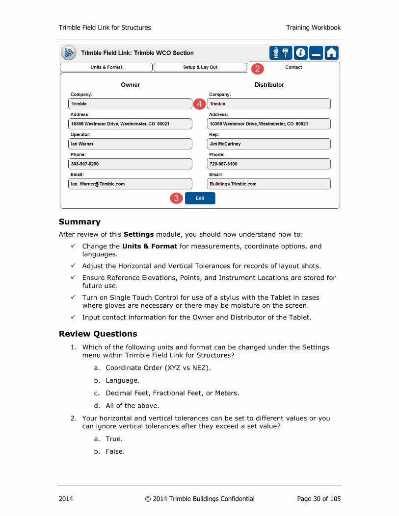
3.3 Contact
Use the Contact tab to input information about the Owner of the tablet and the
Distributor that should be contacted for training, service, maintenance, rentals or
support.
1. Press the Settings menu.
2. The Units & Format menu will automatically be displayed. Press the Contact
tab at the top right of the screen.
3. Press the Edit button at the bottom of the screen to input new or change
contact information.
4. Enter information for both the Owner and Distributor including Company
name, address, operator or representative, phone number and email.
5. Press the Lock button once complete. You can always go back and use the
Edit button to change information.
Trimble Field Link for Structures Training Workbook
2014 © 2014 Trimble Buildings Confidential Page 30 of 105
Summary
After review of this Settings module, you should now understand how to:
Change the Units & Format for measurements, coordinate options, and
languages.
Adjust the Horizontal and Vertical Tolerances for records of layout shots.
Ensure Reference Elevations, Points, and Instrument Locations are stored for
future use.
Turn on Single Touch Control for use of a stylus with the Tablet in cases
where gloves are necessary or there may be moisture on the screen.
Input contact information for the Owner and Distributor of the Tablet.
Review Questions
1. Which of the following units and format can be changed under the Settings
menu within Trimble Field Link for Structures?
a. Coordinate Order (XYZ vs NEZ).
b. Language.
c. Decimal Feet, Fractional Feet, or Meters.
d. All of the above.
2. Your horizontal and vertical tolerances can be set to different values or you
can ignore vertical tolerances after they exceed a set value?
a. True.
b. False.
Trimble Field Link for Structures Training Workbook
2014 © 2014 Trimble Buildings Confidential Page 31 of 105
3. The following options can be selected to help during the layout process under
the Settings menu, Setup and Lay Out:
a. Open Reference Elevation After Instrument Setup.
b. Remember Reference Points.
c. Store Instrument Location after Instrument Setup.
d. Level Telescope after Disabling Visual Layout.
e. Clear Layout Flags.
f. All of the above.
4. Where do you change Trimble Field Link for Structures to operate with a
stylus in lieu of capacitive touch controls?
a. Settings menu, Units and Format.
b. Settings menu, Setup & Lay Out.
c. Settings menu, Contact.
d. Instrument Control and Settings.
5. You can clear layout flags for in and out of tolerance points already laid out
within a job by hitting the Clear Layout Flags button under Settings, Setup &
Lay Out?
a. True.
b. False.
Trimble Field Link for Structures Training Workbook
2014 © 2014 Trimble Buildings Confidential Page 32 of 105
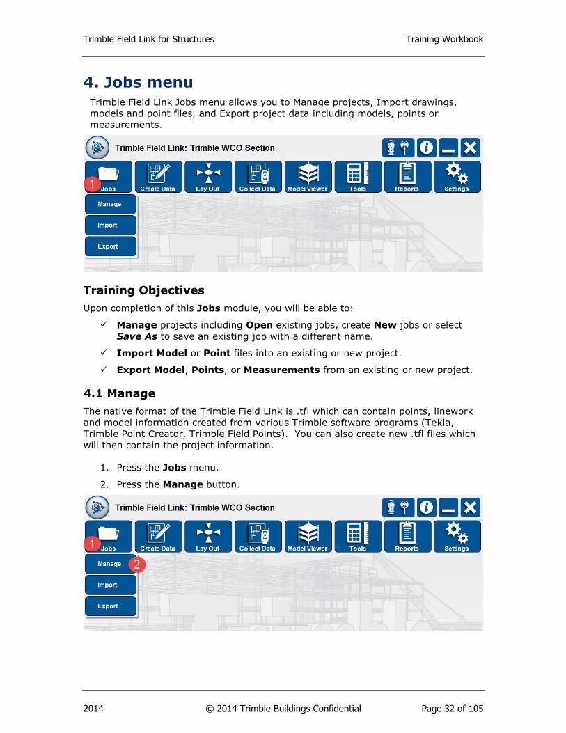
4. Jobs menu
Trimble Field Link Jobs menu allows you to Manage projects, Import drawings,
models and point files, and Export project data including models, points or
measurements.
Training Objectives
Upon completion of this Jobs module, you will be able to:
Manage projects including Open existing jobs, create New jobs or select
Save As to save an existing job with a different name.
Import Model or Point files into an existing or new project.
Export Model, Points, or Measurements from an existing or new project.
4.1 Manage
The native format of the Trimble Field Link is .tfl which can contain points, linework
and model information created from various Trimble software programs (Tekla,
Trimble Point Creator, Trimble Field Points). You can also create new .tfl files which
will then contain the project information.
1. Press the Jobs menu.
2. Press the Manage button.

Trimble Field Link for Structures Training Workbook
2014 © 2014 Trimble Buildings Confidential Page 33 of 105
3. Navigate to the correct folder using the Folder button to select the required
job file. You can also create a new folder by using the Create Folder
button .
4. Trimble Field Link will automatically place new projects under the folder
C:\Users\xxxx\Documents\Trimble Field Link\Jobs unless
otherwise specified for a different folder.
5. Select the .tfl file and make sure the project is highlighted in blue.
6. Press Open to open an existing .tfl project.
7. Press New to create a new .tfl project and type in a new Project Name.
8. Press Save As on an existing .tfl project and type in a new Project Name.
9. Press Sort List By to filter the existing project list by Name or Date. Sorting
by Date will bring the most recently used project to the top of the list.
Note
Only one .tfl file can be opened at a time. Two .tfl files cannot be merged.
In order to add points or model files to a project, you can use the Import
button.
4.2 Import Model
Currently, Trimble Field Link will accept .dwg (AutoCAD 2014 and earlier), .skp
(SketchUp 8 or earlier) or iModel (Bentley) files. Trimble Field Link will convert the
model into a .bldg file type for faster rendering and model viewing.
1. Press the Jobs menu.
Trimble Field Link for Structures Training Workbook
2014 © 2014 Trimble Buildings Confidential Page 34 of 105
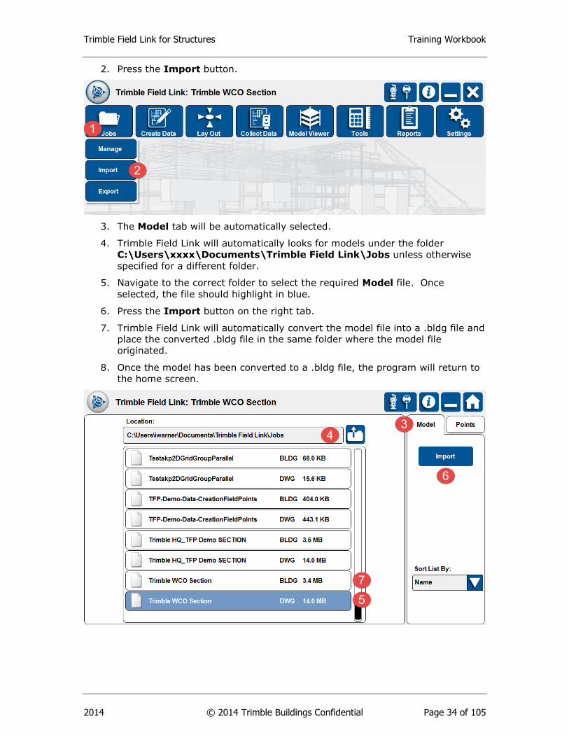
2. Press the Import button.
3. The Model tab will be automatically selected.
4. Trimble Field Link will automatically looks for models under the folder
C:\Users\xxxx\Documents\Trimble Field Link\Jobs unless otherwise
specified for a different folder.
5. Navigate to the correct folder to select the required Model file. Once
selected, the file should highlight in blue.
6. Press the Import button on the right tab.
7. Trimble Field Link will automatically convert the model file into a .bldg file and
place the converted .bldg file in the same folder where the model file
originated.
8. Once the model has been converted to a .bldg file, the program will return to
the home screen.

Trimble Field Link for Structures Training Workbook
2014 © 2014 Trimble Buildings Confidential Page 35 of 105
Tip
Once the model or drawing file has been converted to a .bldg file type, the
original .dwg model or drawing can be deleted from the project folder to
keep the project folder cleaned up and maintain storage capacity. If using
a synchronized folder, you can delete old .bldg and .dwg files to be replaced
by new files to show a model change has been made.
4.3 Import Points
Trimble Field Link can import points created in other software but will require a .csv
type point file.
1. Press the Jobs menu.
2. Press the Import button.
3. The Model tab will be automatically selected. Press the Points tab at the
upper right corner.
4. Navigate to the correct folder to select the required Point file. The selected
file should highlight in blue.
5. You can import the entire point files by selecting All Points. You can also
filter the point file by checking the By Name, By Description, or Contains
boxes and typing in a filter selection.
6. You can place the point file onto a specific layer to by Pressing the Layer
button, then selecting the layer from the Layer drop down list. If you want to
create a new layer, see the Create Data menu, Layer Manager section.
7. Press the Import button.

Trimble Field Link for Structures Training Workbook
2014 © 2014 Trimble Buildings Confidential Page 36 of 105
8. A dialogue box will open stating the number of point(s) imported.
9. Press the OK button.
Note
You can import multiple .csv files into a single .tfl project file. Points with
the same name will be discarded as duplicate points. If points have
different names but the same coordinates, the points will be overlaid. You
may want to add R1, R2, R3 (Revision 1, 2 or 3) to the end of the point
name to signify if a point has been moved before importing the point.
4.4 Export Model
Trimble Field Link can export collected linework or arcs into a .dwg file format. These
lines and arcs can be brought into a modeling software as an as-built layer or help
with as-built modeling.

Trimble Field Link for Structures Training Workbook
2014 © 2014 Trimble Buildings Confidential Page 37 of 105
1. Press the Jobs menu.
2. Press the Export button.
3. The Model tab will be the default selection. Type in the File Name.
4. Press the Choose Layers button.
5. Select the desired layers which should be highlighted in blue or select the
Select All button.
6. Press OK. The selected layers will show in the Selection box.
7. You must select the Export Layout Data check box to export points and
linework.
8. Press the Save button.
9. Trimble Field Link will automatically create an Exports folder and place the
exported .dwg file under C:\Users\xxxx\Documents\Trimble Field
Link\Exports.
10. A dialogue box will open stating “File saved successfully”.
11. Press OK button.

Trimble Field Link for Structures Training Workbook
2014 © 2014 Trimble Buildings Confidential Page 38 of 105
4.5 Export Points
Trimble Field Link can export design points, measured points, or collected points into
a .csv (comma separated value) file.
1. Press the Jobs menu.
2. Press the Export button. The Model tab will be the default selection.
3. Press the Points tab.
4. Type in the File Name.
5. If you have placed points on specific layers, use the Map Options button to
turn layers off or on to help select specific points. To select points, you can
Press the Select All button, or select points individually from the list view.
You can also select points individually by pressing on them or multiple points
using the window selection tool in the map view. See Section 5.1 for more on
Map View and Map Options.
6. Select the Design Location or Staked Location check boxes. The Design
Location are the points as originally created in TFL or other software. The
Staked Location will contain the points actual staked location.
7. Press Save.
8. Trimble Field Link will automatically create an Exports folder and place the
exported .csv file under C:\Users\xxxx\Documents\Trimble Field
Link\Exports.
9. A dialogue box will open stating “File saved successfully”.
10. Press the OK button.
4.6 Export Measurements
Trimble Field Link can export raw data for your entire project including setups,
points, collected points or collected linework into a .csv file format.
Trimble Field Link for Structures Training Workbook
2014 © 2014 Trimble Buildings Confidential Page 39 of 105
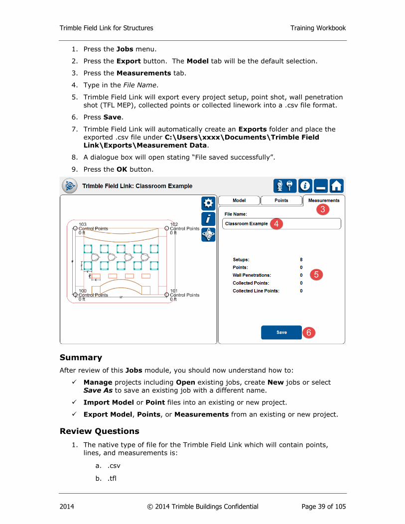
1. Press the Jobs menu.
2. Press the Export button. The Model tab will be the default selection.
3. Press the Measurements tab.
4. Type in the File Name.
5. Trimble Field Link will export every project setup, point shot, wall penetration
shot (TFL MEP), collected points or collected linework into a .csv file format.
6. Press Save.
7. Trimble Field Link will automatically create an Exports folder and place the
exported .csv file under C:\Users\xxxx\Documents\Trimble Field
Link\Exports\Measurement Data.
8. A dialogue box will open stating “File saved successfully”.
9. Press the OK button.
Summary
After review of this Jobs module, you should now understand how to:
Manage projects including Open existing jobs, create New jobs or select
Save As to save an existing job with a different name.
Import Model or Point files into an existing or new project.
Export Model, Points, or Measurements from an existing or new project.
Review Questions
1. The native type of file for the Trimble Field Link which will contain points,
lines, and measurements is:
a. .csv
b. .tfl
Trimble Field Link for Structures Training Workbook
2014 © 2014 Trimble Buildings Confidential Page 40 of 105
c. .dwg
d. .skp
e. All of the above.
2. You can create a new .tfl project and import points, drawings or models into
the empty project.
a. True.
b. False.
3. Trimble Field Link will convert your drawings or models into which type of file
before it is imported into your job file?
a. .bldg
b. .dwg
c. .tfl
d. .skp
4. Which of the follow type of information can you export from a .tfl job file?
a. Collected lines and arcs.
b. Design or Measured Points.
c. Measurements including setups, points, and linework.
d. All of the above.
5. The default location to store job files, converted models, and exported
information for Trimble Field Link is on the Windows 7 desktop.
a. True
b. False
Trimble Field Link for Structures Training Workbook
2014 © 2014 Trimble Buildings Confidential Page 41 of 105
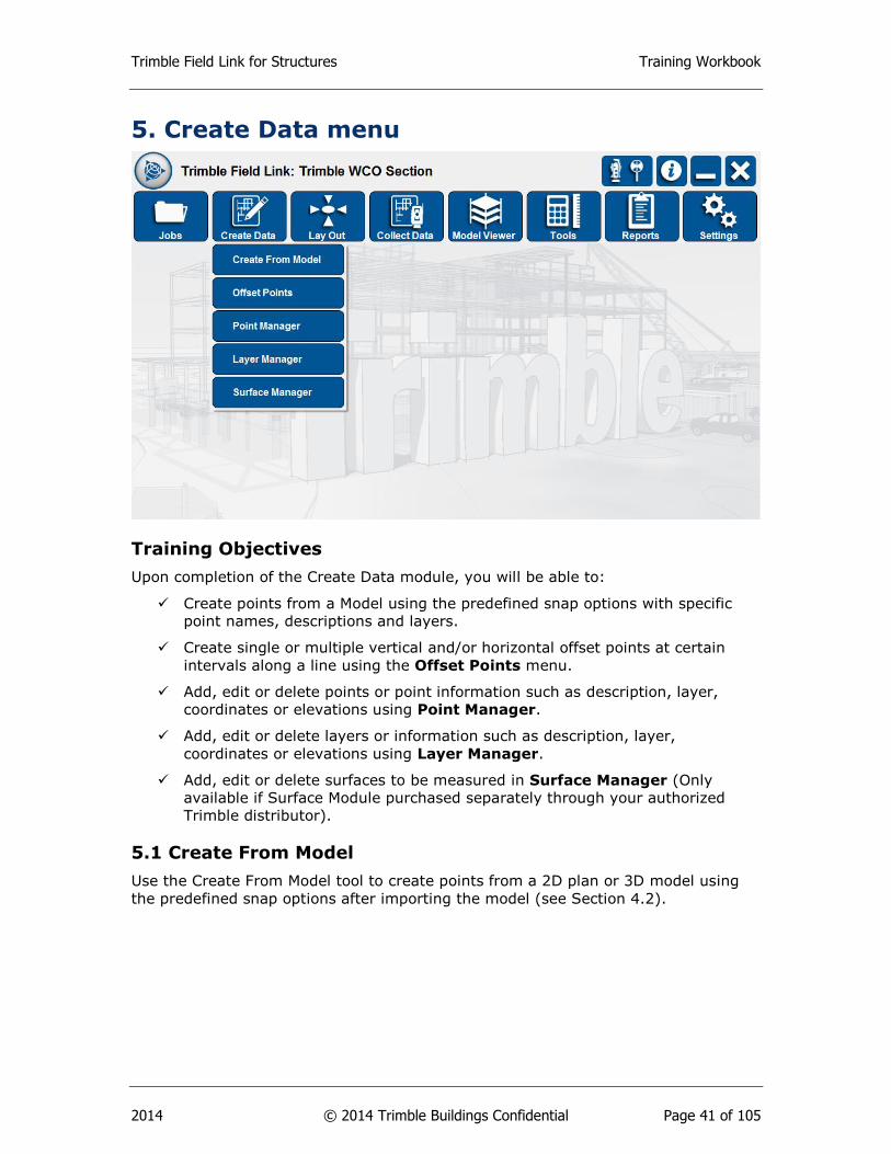
5. Create Data menu
Training Objectives
Upon completion of the Create Data module, you will be able to:
Create points from a Model using the predefined snap options with specific
point names, descriptions and layers.
Create single or multiple vertical and/or horizontal offset points at certain
intervals along a line using the Offset Points menu.
Add, edit or delete points or point information such as description, layer,
coordinates or elevations using Point Manager.
Add, edit or delete layers or information such as description, layer,
coordinates or elevations using Layer Manager.
Add, edit or delete surfaces to be measured in Surface Manager (Only
available if Surface Module purchased separately through your authorized
Trimble distributor).
5.1 Create From Model
Use the Create From Model tool to create points from a 2D plan or 3D model using
the predefined snap options after importing the model (see Section 4.2).
Trimble Field Link for Structures Training Workbook
2014 © 2014 Trimble Buildings Confidential Page 42 of 105
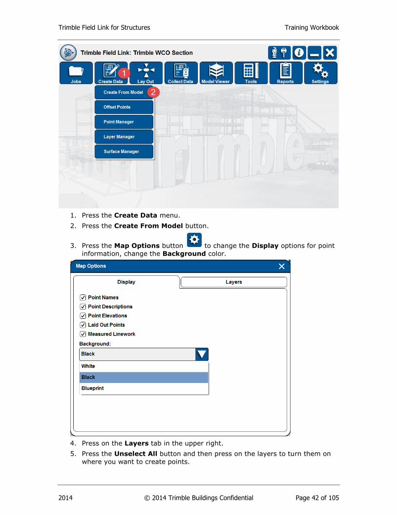
1. Press the Create Data menu.
2. Press the Create From Model button.
3. Press the Map Options button to change the Display options for point
information, change the Background color.
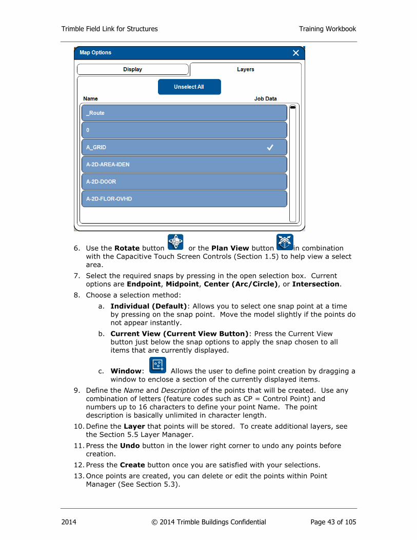
4. Press on the Layers tab in the upper right.
5. Press the Unselect All button and then press on the layers to turn them on
where you want to create points.
Trimble Field Link for Structures Training Workbook
2014 © 2014 Trimble Buildings Confidential Page 43 of 105
6. Use the Rotate button or the Plan View button in combination
with the Capacitive Touch Screen Controls (Section 1.5) to help view a select
area.
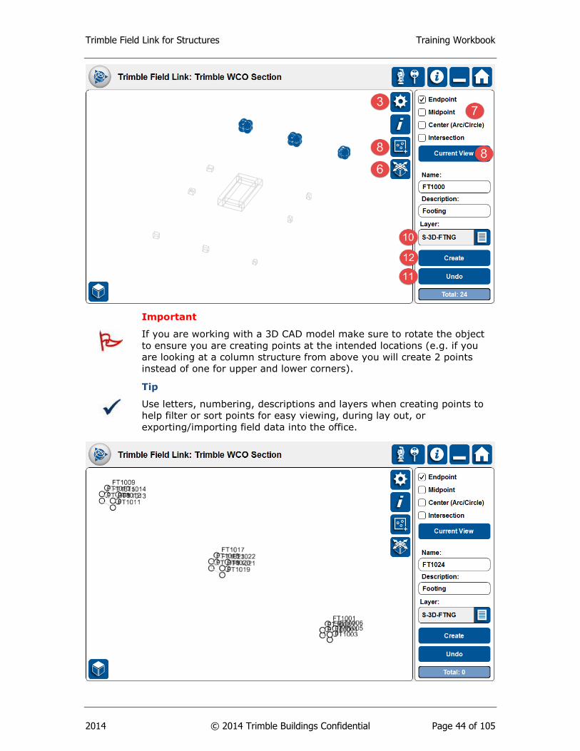
7. Select the required snaps by pressing in the open selection box. Current
options are Endpoint, Midpoint, Center (Arc/Circle), or Intersection.
8. Choose a selection method:
a. Individual (Default): Allows you to select one snap point at a time
by pressing on the snap point. Move the model slightly if the points do
not appear instantly.
b. Current View (Current View Button): Press the Current View
button just below the snap options to apply the snap chosen to all
items that are currently displayed.
c. Window: Allows the user to define point creation by dragging a
window to enclose a section of the currently displayed items.
9. Define the Name and Description of the points that will be created. Use any
combination of letters (feature codes such as CP = Control Point) and
numbers up to 16 characters to define your point Name. The point
description is basically unlimited in character length.
10. Define the Layer that points will be stored. To create additional layers, see
the Section 5.5 Layer Manager.
11. Press the Undo button in the lower right corner to undo any points before
creation.
12. Press the Create button once you are satisfied with your selections.
13. Once points are created, you can delete or edit the points within Point
Manager (See Section 5.3).
Trimble Field Link for Structures Training Workbook
2014 © 2014 Trimble Buildings Confidential Page 44 of 105
Important
If you are working with a 3D CAD model make sure to rotate the object
to ensure you are creating points at the intended locations (e.g. if you
are looking at a column structure from above you will create 2 points
instead of one for upper and lower corners).
Tip
Use letters, numbering, descriptions and layers when creating points to
help filter or sort points for easy viewing, during lay out, or
exporting/importing field data into the office.

Trimble Field Link for Structures Training Workbook
2014 © 2014 Trimble Buildings Confidential Page 45 of 105
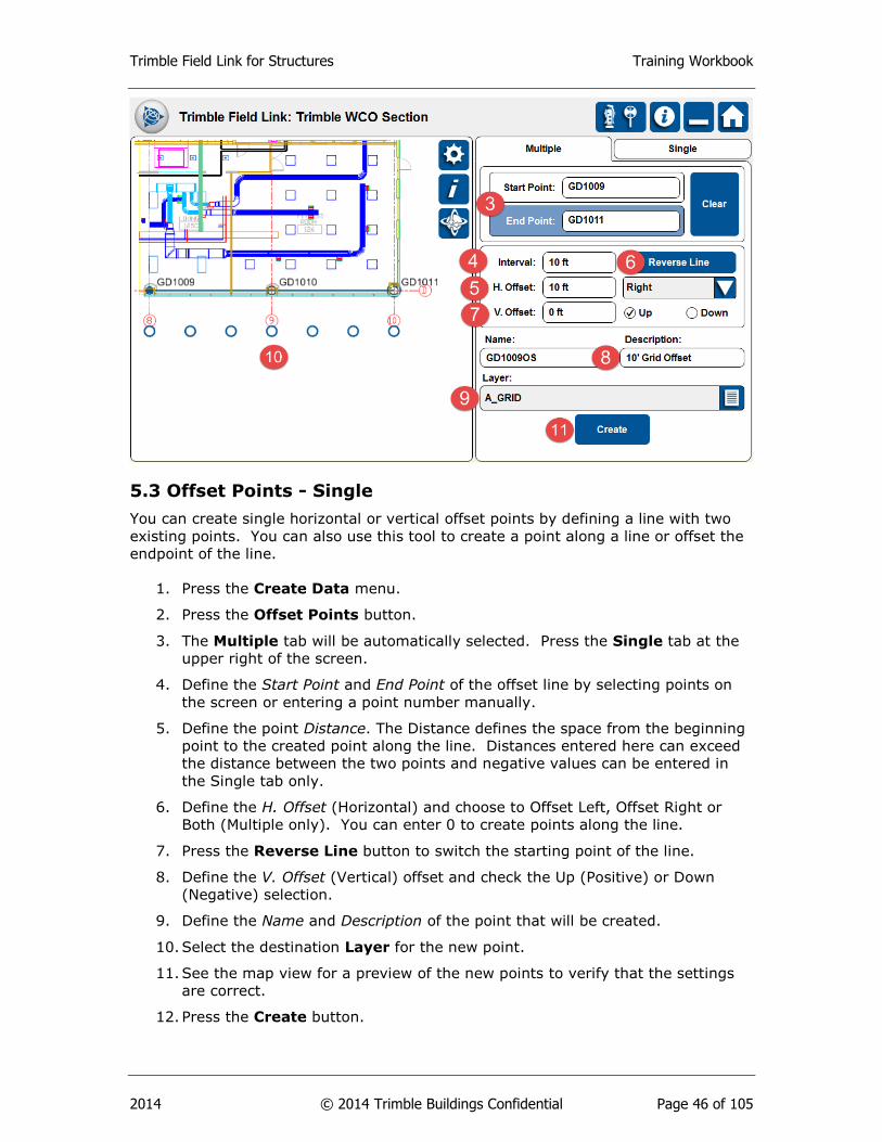
5.2 Offset Points - Multiple
The Offset Points tool allows you to create multiple horizontal or vertical offset points
by defining a line with two existing points. You can also use this tool to create points
along a line.
1. Press the Create Data menu.
2. Press the Offset Points button. The Multiple tab will be automatically
selected.
3. Define the Start Point and End Point of the offset line by selecting points on
the screen or entering a point number manually.
4. Define the point Interval. The Interval defines the space between the new
points along the line. The Interval length cannot exceed the distance
between the two selected points and negative values cannot be entered in the
Multiple tab.
5. Define the H. Offset (Horizontal) and choose to Offset Left, Offset Right or
Both (Multiple only). You can enter 0 to create points along the line.
6. Press the Reverse Line button to switch the starting point of the line.
7. Define the V. Offset (Vertical) offset and check the Up (Positive) or Down
(Negative) selection.
8. Define the Name and Description of the points that will be created.
9. Select the destination Layer for the new points.
10. See the map view for a preview of the new points to verify that the settings
are correct.
11. Press the Create button.
Trimble Field Link for Structures Training Workbook
2014 © 2014 Trimble Buildings Confidential Page 46 of 105
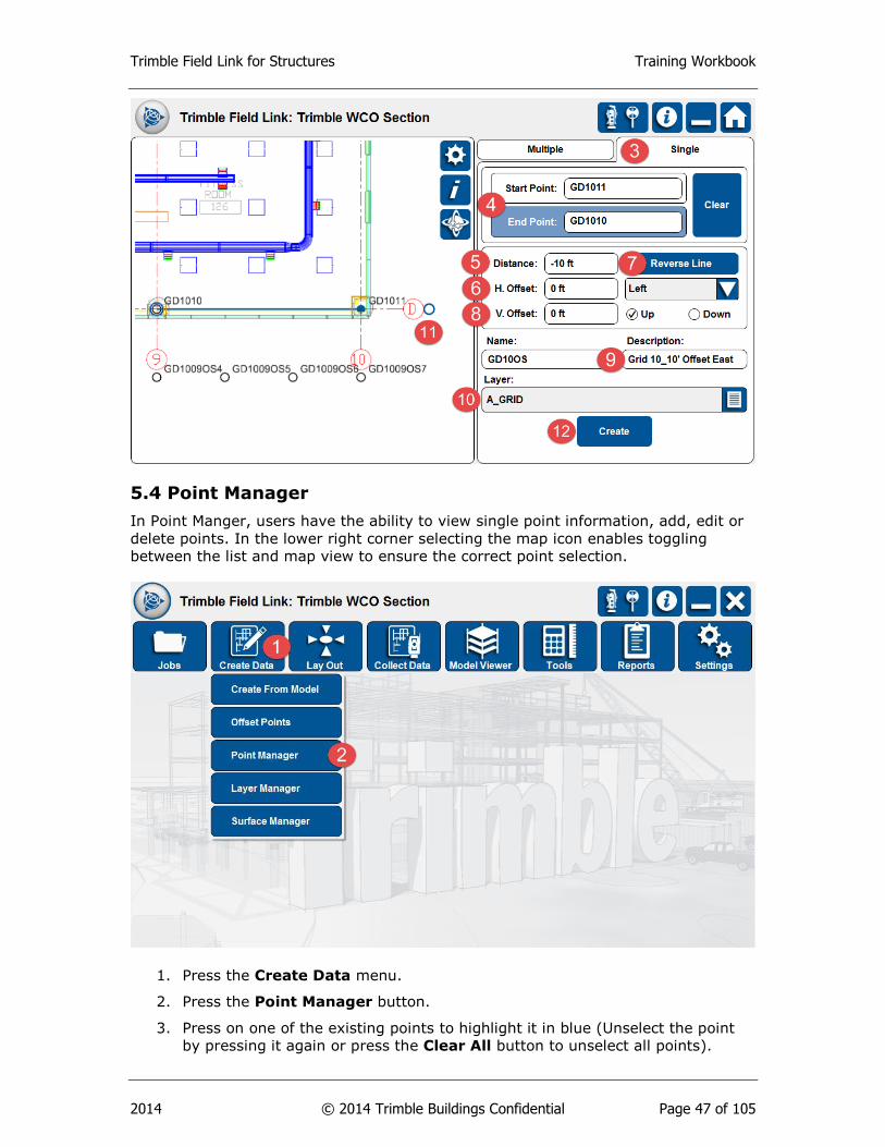
5.3 Offset Points - Single
You can create single horizontal or vertical offset points by defining a line with two
existing points. You can also use this tool to create a point along a line or offset the
endpoint of the line.
1. Press the Create Data menu.
2. Press the Offset Points button.
3. The Multiple tab will be automatically selected. Press the Single tab at the
upper right of the screen.
4. Define the Start Point and End Point of the offset line by selecting points on
the screen or entering a point number manually.
5. Define the point Distance. The Distance defines the space from the beginning
point to the created point along the line. Distances entered here can exceed
the distance between the two points and negative values can be entered in
the Single tab only.
6. Define the H. Offset (Horizontal) and choose to Offset Left, Offset Right or
Both (Multiple only). You can enter 0 to create points along the line.
7. Press the Reverse Line button to switch the starting point of the line.
8. Define the V. Offset (Vertical) offset and check the Up (Positive) or Down
(Negative) selection.
9. Define the Name and Description of the point that will be created.
10. Select the destination Layer for the new point.
11. See the map view for a preview of the new points to verify that the settings
are correct.
12. Press the Create button.
Trimble Field Link for Structures Training Workbook
2014 © 2014 Trimble Buildings Confidential Page 47 of 105
5.4 Point Manager
In Point Manger, users have the ability to view single point information, add, edit or
delete points. In the lower right corner selecting the map icon enables toggling
between the list and map view to ensure the correct point selection.
1. Press the Create Data menu.
2. Press the Point Manager button.
3. Press on one of the existing points to highlight it in blue (Unselect the point
by pressing it again or press the Clear All button to unselect all points).
Trimble Field Link for Structures Training Workbook
2014 © 2014 Trimble Buildings Confidential Page 48 of 105
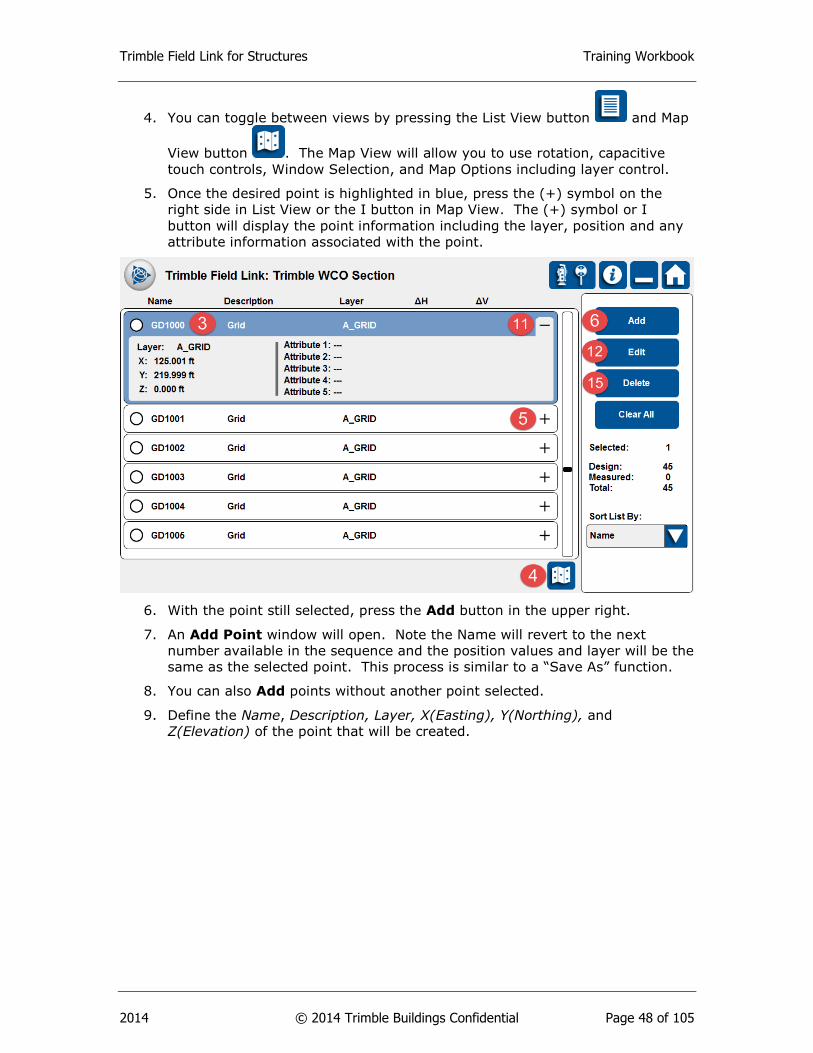
4. You can toggle between views by pressing the List View button and Map
View button . The Map View will allow you to use rotation, capacitive
touch controls, Window Selection, and Map Options including layer control.
5. Once the desired point is highlighted in blue, press the (+) symbol on the
right side in List View or the I button in Map View. The (+) symbol or I
button will display the point information including the layer, position and any
attribute information associated with the point.
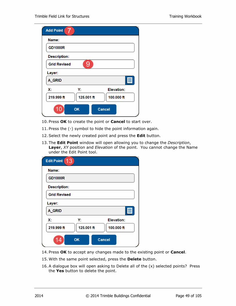
6. With the point still selected, press the Add button in the upper right.
7. An Add Point window will open. Note the Name will revert to the next
number available in the sequence and the position values and layer will be the
same as the selected point. This process is similar to a “Save As” function.
8. You can also Add points without another point selected.
9. Define the Name, Description, Layer, X(Easting), Y(Northing), and
Z(Elevation) of the point that will be created.
Trimble Field Link for Structures Training Workbook
2014 © 2014 Trimble Buildings Confidential Page 49 of 105
10. Press OK to create the point or Cancel to start over.
11. Press the (-) symbol to hide the point information again.
12. Select the newly created point and press the Edit button.
13. The Edit Point window will open allowing you to change the Description,
Layer, XY position and Elevation of the point. You cannot change the Name
under the Edit Point tool.
14. Press OK to accept any changes made to the existing point or Cancel.
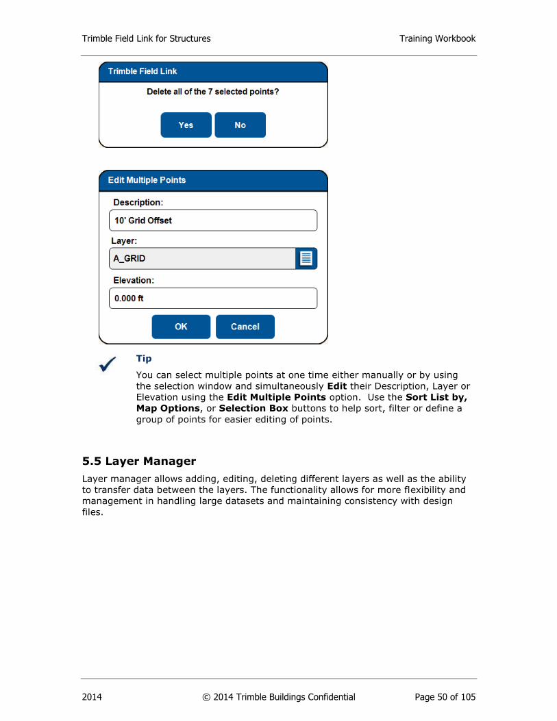
15. With the same point selected, press the Delete button.
16. A dialogue box will open asking to Delete all of the (x) selected points? Press
the Yes button to delete the point.
Trimble Field Link for Structures Training Workbook
2014 © 2014 Trimble Buildings Confidential Page 50 of 105
Tip
You can select multiple points at one time either manually or by using
the selection window and simultaneously Edit their Description, Layer or
Elevation using the Edit Multiple Points option. Use the Sort List by,
Map Options, or Selection Box buttons to help sort, filter or define a
group of points for easier editing of points.
5.5 Layer Manager
Layer manager allows adding, editing, deleting different layers as well as the ability
to transfer data between the layers. The functionality allows for more flexibility and
management in handling large datasets and maintaining consistency with design
files.
Trimble Field Link for Structures Training Workbook
2014 © 2014 Trimble Buildings Confidential Page 51 of 105
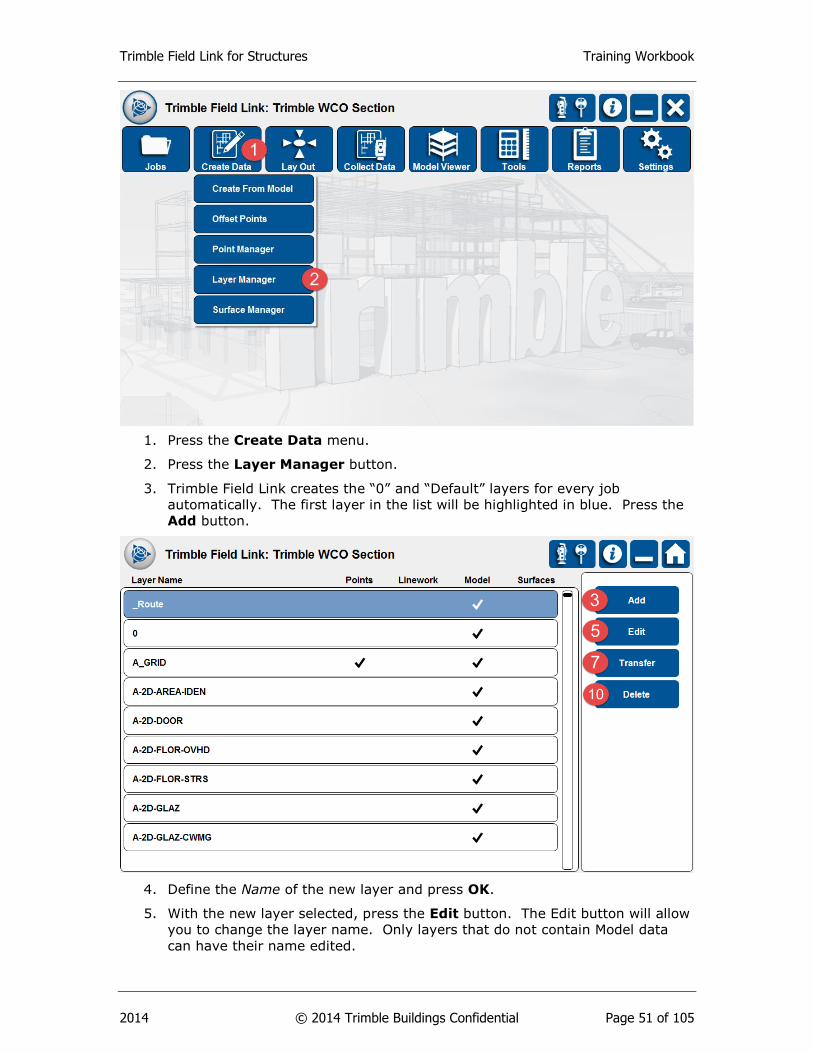
1. Press the Create Data menu.
2. Press the Layer Manager button.
3. Trimble Field Link creates the “0” and “Default” layers for every job
automatically. The first layer in the list will be highlighted in blue. Press the
Add button.
4. Define the Name of the new layer and press OK.
5. With the new layer selected, press the Edit button. The Edit button will allow
you to change the layer name. Only layers that do not contain Model data
can have their name edited.

Trimble Field Link for Structures Training Workbook
2014 © 2014 Trimble Buildings Confidential Page 52 of 105
6. Once the new Name has been defined, press the OK button.
7. Select a layer with a check mark under Points, Linework or Surfaces and
press the Transfer button.
8. The Select Layer menu will open. Press the List button on the right of the
menu and select a new layer to Transfer the job data.
9. Press OK and you will see the check marks now on the new layer.
10. Select a layer with no job or Model data and press the Delete button.
11. The layer will be automatically deleted.
5.6 Surface Manager (Optional Module)
The surface analysis module is available as a separate item for users who are using
or have purchased Trimble Field Link v2.0.0 or later. This module is available for
purchase through your authorized Trimble distributor and is a separate installation
on BCIM. Surface Manger allows users to add, edit and delete surfaces.
Trimble Field Link for Structures Training Workbook
2014 © 2014 Trimble Buildings Confidential Page 53 of 105
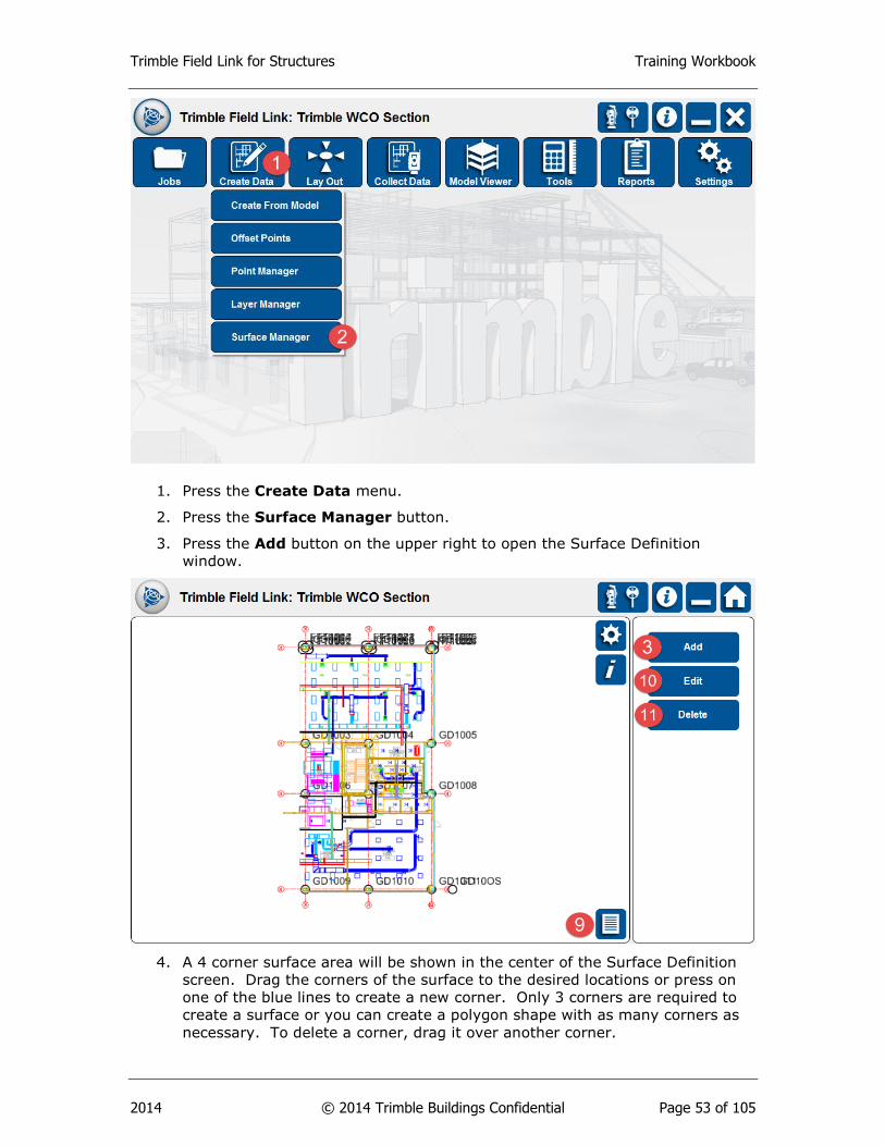
1. Press the Create Data menu.
2. Press the Surface Manager button.
3. Press the Add button on the upper right to open the Surface Definition
window.
4. A 4 corner surface area will be shown in the center of the Surface Definition
screen. Drag the corners of the surface to the desired locations or press on
one of the blue lines to create a new corner. Only 3 corners are required to
create a surface or you can create a polygon shape with as many corners as
necessary. To delete a corner, drag it over another corner.

Trimble Field Link for Structures Training Workbook
2014 © 2014 Trimble Buildings Confidential Page 54 of 105
5. Define the Name and Layer of the new Surface and press OK.
6. Press the Add button again.
7. Pan, zoom or rotate to a different area and press the Reset button to
generate a new 4 corner area centered on the current view.
8. Define the Name and Layer of the new Surface and press OK.
9. You can now select the individual surfaces by pressing on them directly in the
Map or List View.
10. With the new surface selected, press the Edit button. The Edit button will
allow you to modify the surface Name, layer or area included.
11. Once the Edits are complete, press the OK button.
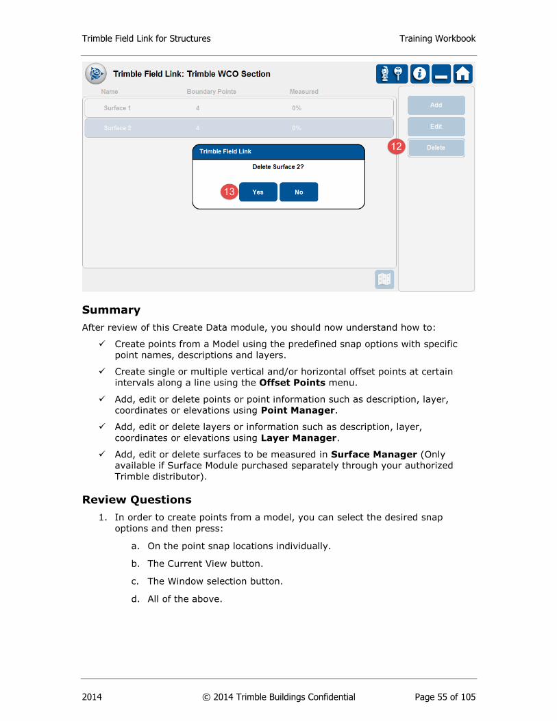
12. Select any surface and press the Delete button.
13. Confirm by pressing the Yes button to delete.
Trimble Field Link for Structures Training Workbook
2014 © 2014 Trimble Buildings Confidential Page 55 of 105
Summary
After review of this Create Data module, you should now understand how to:
Create points from a Model using the predefined snap options with specific
point names, descriptions and layers.
Create single or multiple vertical and/or horizontal offset points at certain
intervals along a line using the Offset Points menu.
Add, edit or delete points or point information such as description, layer,
coordinates or elevations using Point Manager.
Add, edit or delete layers or information such as description, layer,
coordinates or elevations using Layer Manager.
Add, edit or delete surfaces to be measured in Surface Manager (Only
available if Surface Module purchased separately through your authorized
Trimble distributor).
Review Questions
1. In order to create points from a model, you can select the desired snap
options and then press:
a. On the point snap locations individually.
b. The Current View button.
c. The Window selection button.
d. All of the above.
Trimble Field Link for Structures Training Workbook
2014 © 2014 Trimble Buildings Confidential Page 56 of 105
2. You can create offset points past the end point of the line or with negative
values under the Multiple tab.
a. True
b. False
3. Which of the following point information items cannot be changed under Edit
in Point Manger?
a. Name
b. Description
c. Layer
d. XY or NE position
e. Elevation
4. The Layer Manger menu allows you to create new, edit names, transfer data
or delete layers.
a. True
b. False
5. To define a surface area for later collection under Surface Manager, you can
select the area by which of the following?
a. Press the Reset button on a specific view.
b. Drag the corners to the desired locations.
c. Press along the surface line to create a new corner for polygon type
areas.
d. All of the above.
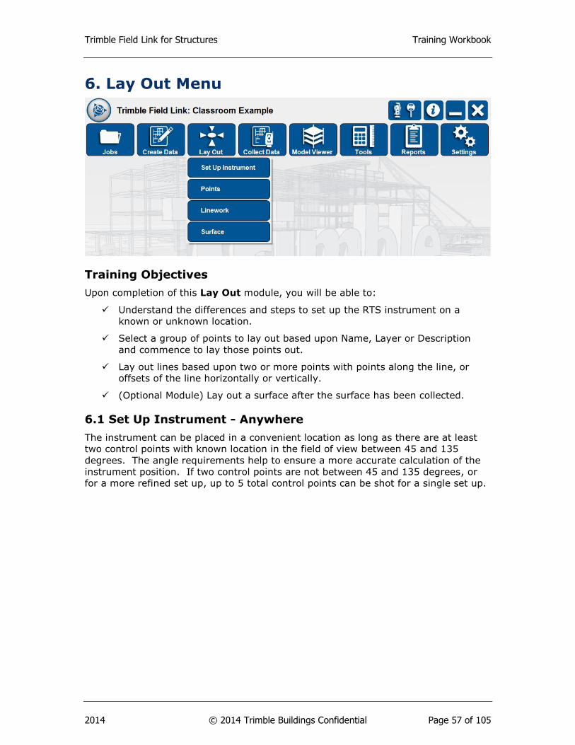
Trimble Field Link for Structures Training Workbook
2014 © 2014 Trimble Buildings Confidential Page 57 of 105
6. Lay Out Menu
Training Objectives
Upon completion of this Lay Out module, you will be able to:
Understand the differences and steps to set up the RTS instrument on a
known or unknown location.
Select a group of points to lay out based upon Name, Layer or Description
and commence to lay those points out.
Lay out lines based upon two or more points with points along the line, or
offsets of the line horizontally or vertically.
(Optional Module) Lay out a surface after the surface has been collected.
6.1 Set Up Instrument - Anywhere
The instrument can be placed in a convenient location as long as there are at least
two control points with known location in the field of view between 45 and 135
degrees. The angle requirements help to ensure a more accurate calculation of the
instrument position. If two control points are not between 45 and 135 degrees, or
for a more refined set up, up to 5 total control points can be shot for a single set up.

Trimble Field Link for Structures Training Workbook
2014 © 2014 Trimble Buildings Confidential Page 58 of 105
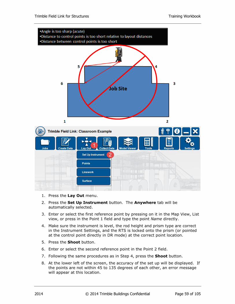
Trimble Field Link for Structures Training Workbook
2014 © 2014 Trimble Buildings Confidential Page 59 of 105
1. Press the Lay Out menu.
2. Press the Set Up Instrument button. The Anywhere tab will be
automatically selected.
3. Enter or select the first reference point by pressing on it in the Map View, List
view, or press in the Point 1 field and type the point Name directly.
4. Make sure the instrument is level, the rod height and prism type are correct
in the Instrument Settings, and the RTS is locked onto the prism (or pointed
at the control point directly in DR mode) at the correct point location.
5. Press the Shoot button.
6. Enter or select the second reference point in the Point 2 field.
7. Following the same procedures as in Step 4, press the Shoot button.
8. At the lower left of the screen, the accuracy of the set up will be displayed. If
the points are not within 45 to 135 degrees of each other, an error message
will appear at this location.
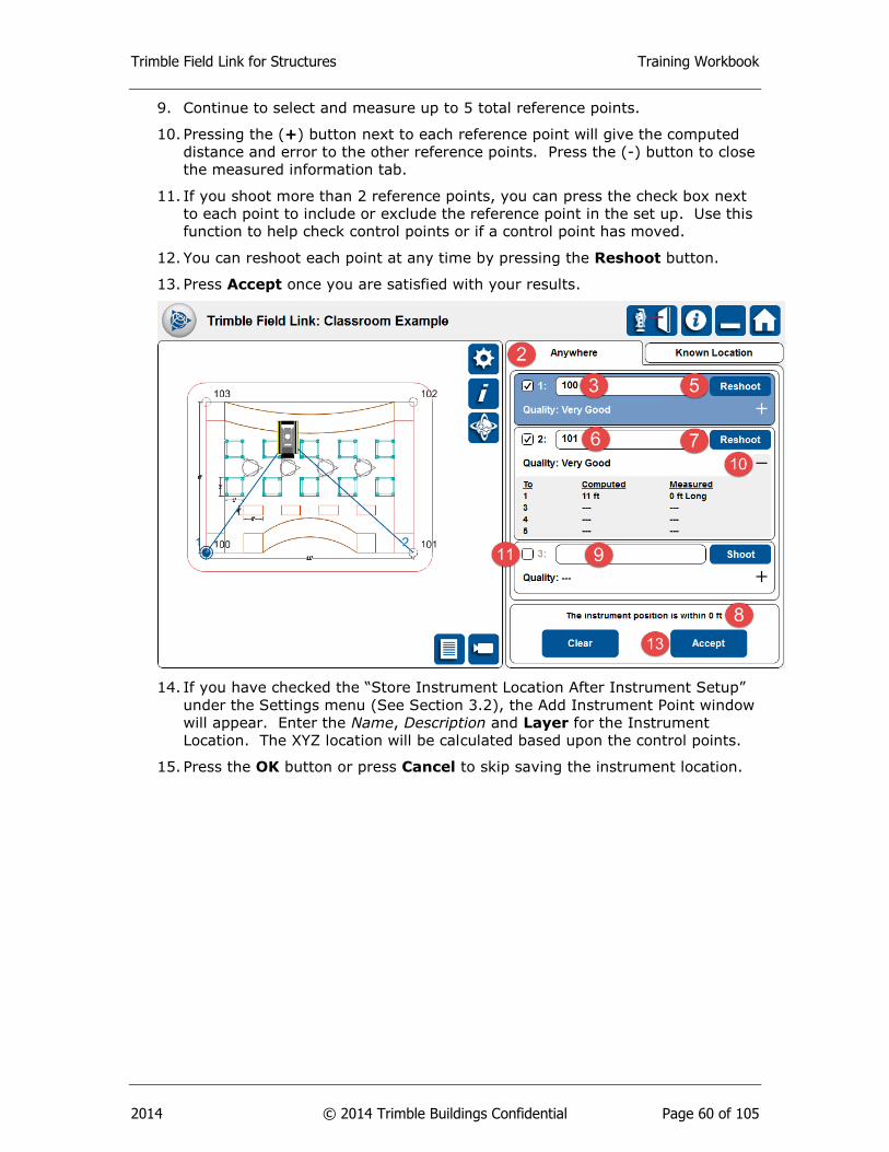
Trimble Field Link for Structures Training Workbook
2014 © 2014 Trimble Buildings Confidential Page 60 of 105
9. Continue to select and measure up to 5 total reference points.
10. Pressing the (+) button next to each reference point will give the computed
distance and error to the other reference points. Press the (-) button to close
the measured information tab.
11. If you shoot more than 2 reference points, you can press the check box next
to each point to include or exclude the reference point in the set up. Use this
function to help check control points or if a control point has moved.
12. You can reshoot each point at any time by pressing the Reshoot button.
13. Press Accept once you are satisfied with your results.
14. If you have checked the “Store Instrument Location After Instrument Setup”
under the Settings menu (See Section 3.2), the Add Instrument Point window
will appear. Enter the Name, Description and Layer for the Instrument
Location. The XYZ location will be calculated based upon the control points.
15. Press the OK button or press Cancel to skip saving the instrument location.

Trimble Field Link for Structures Training Workbook
2014 © 2014 Trimble Buildings Confidential Page 61 of 105
6.2 Set Up Instrument – Known Location
When setting up over a known point, the instrument is positioned (leveled and
centered above the point with known coordinates x, y and z; in the example below
point 5), and the prism is positioned (or DR is pointing) to another point with known
coordinates (in the example below point 2). Knowing the location of both points, the
software determines the initial instrument orientation and using basic mathematic
principles (knowing the angle and distance) can calculate position of other points in
the site.
1. Press the Lay Out menu.
2. Press the Set Up Instrument button. The Anywhere tab will be
automatically selected.

Trimble Field Link for Structures Training Workbook
2014 © 2014 Trimble Buildings Confidential Page 62 of 105
3. Press the Known Location tab at the top right of the screen. The Station
field will automatically be highlighted in blue.
4. Enter or select the Station of the instrument by pressing on it in the Map
View, List view, or press in the Station field and type the point Name directly.
Notice an image of the RTS will be placed over the selected point.
5. Press on the Backsight field and make sure it is highlighted in blue.
6. Enter or select the Backsight of the instrument by pressing on it in the Map
View, List view, or press in the Backsight field and type the point Name
directly.
7. Make sure the instrument is level and centered above the reference point, the
rod height and prism type are correct in the Instrument Settings, and the RTS
is locked onto the prism (or pointed at the control point directly in DR mode)
at the correct point location.
8. Press the Shoot button. You can press the Reshoot button if you are not
satisfied with the results or need to reposition the prism or DR.
9. The Measured Distance Between Points and the Computed Distance
Between Points will be displayed at the lower right of the screen.
10. Press Accept once you are satisfied with your results.
Tip
You can also start a job with no points or data and conduct a No Data
Setup as covered under Section 7.1. The No Data Setup can be
completed under the Lay Out or Collect Data menus.
6.3 Lay Out Points
Points can be created within the Trimble Field Link for Structures (See Section 5) or
with office software such as Vico, Tekla, SketchUp, Trimble Business Center, Trimble
Field Points for AutoCAD or Revit, Trimble Point Creator, or even other non-Trimble
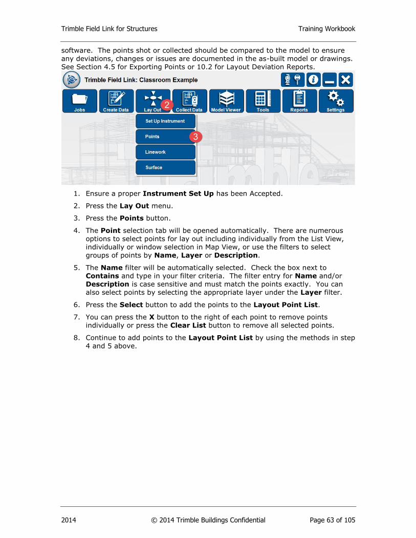
Trimble Field Link for Structures Training Workbook
2014 © 2014 Trimble Buildings Confidential Page 63 of 105
software. The points shot or collected should be compared to the model to ensure
any deviations, changes or issues are documented in the as-built model or drawings.
See Section 4.5 for Exporting Points or 10.2 for Layout Deviation Reports.
1. Ensure a proper Instrument Set Up has been Accepted.
2. Press the Lay Out menu.
3. Press the Points button.
4. The Point selection tab will be opened automatically. There are numerous
options to select points for lay out including individually from the List View,
individually or window selection in Map View, or use the filters to select
groups of points by Name, Layer or Description.
5. The Name filter will be automatically selected. Check the box next to
Contains and type in your filter criteria. The filter entry for Name and/or
Description is case sensitive and must match the points exactly. You can
also select points by selecting the appropriate layer under the Layer filter.
6. Press the Select button to add the points to the Layout Point List.
7. You can press the X button to the right of each point to remove points
individually or press the Clear List button to remove all selected points.
8. Continue to add points to the Layout Point List by using the methods in step
4 and 5 above.
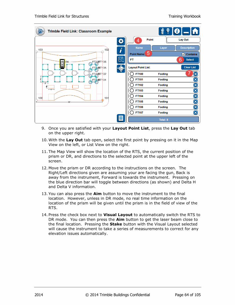
Trimble Field Link for Structures Training Workbook
2014 © 2014 Trimble Buildings Confidential Page 64 of 105
9. Once you are satisfied with your Layout Point List, press the Lay Out tab
on the upper right.
10. With the Lay Out tab open, select the first point by pressing on it in the Map
View on the left, or List View on the right.
11. The Map View will show the location of the RTS, the current position of the
prism or DR, and directions to the selected point at the upper left of the
screen.
12. Move the prism or DR according to the instructions on the screen. The
Right/Left directions given are assuming your are facing the gun, Back is
away from the instrument, Forward is towards the instrument. Pressing on
the blue direction bar will toggle between directions (as shown) and Delta H
and Delta V information.
13. You can also press the Aim button to move the instrument to the final
location. However, unless in DR mode, no real time information on the
location of the prism will be given until the prism is in the field of view of the
RTS.
14. Press the check box next to Visual Layout to automatically switch the RTS to
DR mode. You can then press the Aim button to get the laser beam close to
the final location. Pressing the Stake button with the Visual Layout selected
will cause the instrument to take a series of measurements to correct for any
elevation issues automatically.
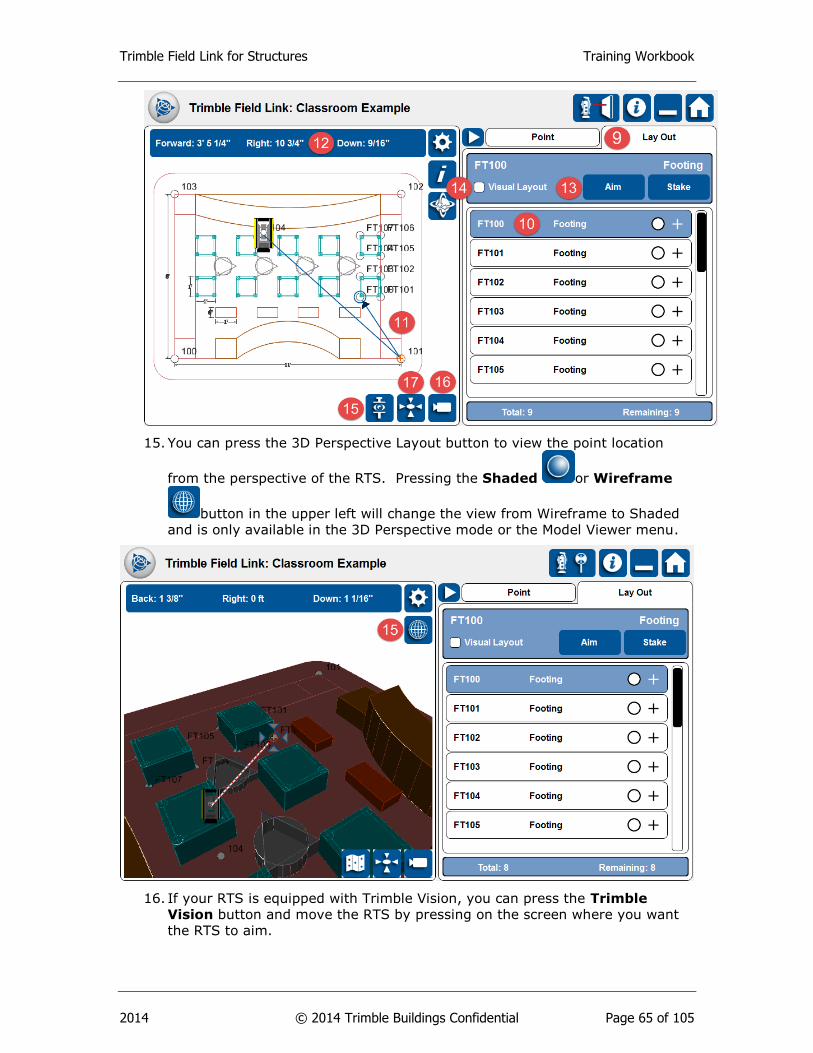
Trimble Field Link for Structures Training Workbook
2014 © 2014 Trimble Buildings Confidential Page 65 of 105
15. You can press the 3D Perspective Layout button to view the point location
from the perspective of the RTS. Pressing the Shaded or Wireframe
button in the upper left will change the view from Wireframe to Shaded
and is only available in the 3D Perspective mode or the Model Viewer menu.
16. If your RTS is equipped with Trimble Vision, you can press the Trimble
Vision button and move the RTS by pressing on the screen where you want
the RTS to aim.

Trimble Field Link for Structures Training Workbook
2014 © 2014 Trimble Buildings Confidential Page 66 of 105
17. When you are within 3’ of the point, the Map View will change to a Bulls’ Eye
view. Once you are within the tolerances input in the Settings menu (See
Section 3.2 Setup & Lay Out) the Bulls’ Eye will be surrounded in green
arrows and the tablet will announce “Stake Point”. The user can bring up the
bulls’ eye view by selecting the bull’s-eye icon or switch back to the Map
View, 3D Perspective View, or Trimble Vision by pressing on the respective
button.
18. Make sure the rod and prism are plum or the DR laser is in the correct
position, then press the Stake button.
19. The Layout Results window will appear giving the staked point information.
Press the Cancel button if you need to change the tolerance settings or stake
the point again for a more accurate shot.
20. Press the Next or Nearest button if you are satisfied with the layout results.
Next will select the next point sequentially in the list, Nearest will select the
closest point to your current location.
21. Press the Report button to create a Field Report with point design and staked
information, photos, and input additional information.
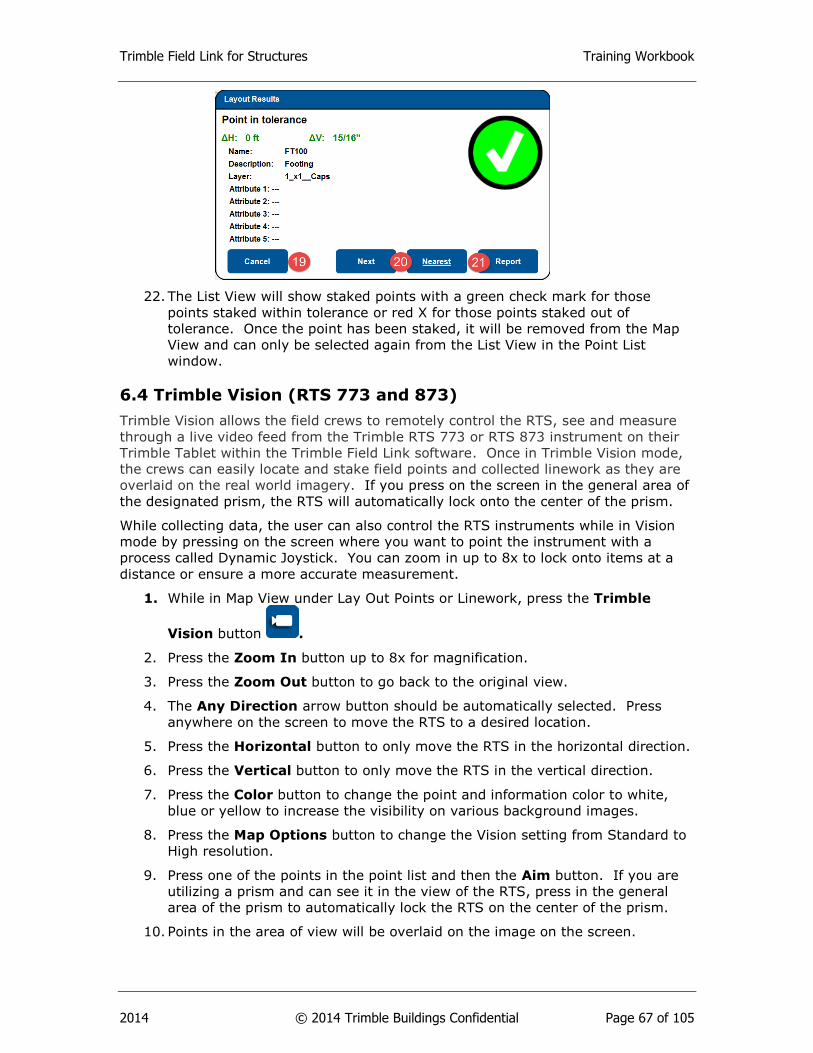
Trimble Field Link for Structures Training Workbook
2014 © 2014 Trimble Buildings Confidential Page 67 of 105
22. The List View will show staked points with a green check mark for those
points staked within tolerance or red X for those points staked out of
tolerance. Once the point has been staked, it will be removed from the Map
View and can only be selected again from the List View in the Point List
window.
6.4 Trimble Vision (RTS 773 and 873)
Trimble Vision allows the field crews to remotely control the RTS, see and measure
through a live video feed from the Trimble RTS 773 or RTS 873 instrument on their
Trimble Tablet within the Trimble Field Link software. Once in Trimble Vision mode,
the crews can easily locate and stake field points and collected linework as they are
overlaid on the real world imagery. If you press on the screen in the general area of
the designated prism, the RTS will automatically lock onto the center of the prism.
While collecting data, the user can also control the RTS instruments while in Vision
mode by pressing on the screen where you want to point the instrument with a
process called Dynamic Joystick. You can zoom in up to 8x to lock onto items at a
distance or ensure a more accurate measurement.
1. While in Map View under Lay Out Points or Linework, press the Trimble
Vision button .
2. Press the Zoom In button up to 8x for magnification.
3. Press the Zoom Out button to go back to the original view.
4. The Any Direction arrow button should be automatically selected. Press
anywhere on the screen to move the RTS to a desired location.
5. Press the Horizontal button to only move the RTS in the horizontal direction.
6. Press the Vertical button to only move the RTS in the vertical direction.
7. Press the Color button to change the point and information color to white,
blue or yellow to increase the visibility on various background images.
8. Press the Map Options button to change the Vision setting from Standard to
High resolution.
9. Press one of the points in the point list and then the Aim button. If you are
utilizing a prism and can see it in the view of the RTS, press in the general
area of the prism to automatically lock the RTS on the center of the prism.
10. Points in the area of view will be overlaid on the image on the screen.
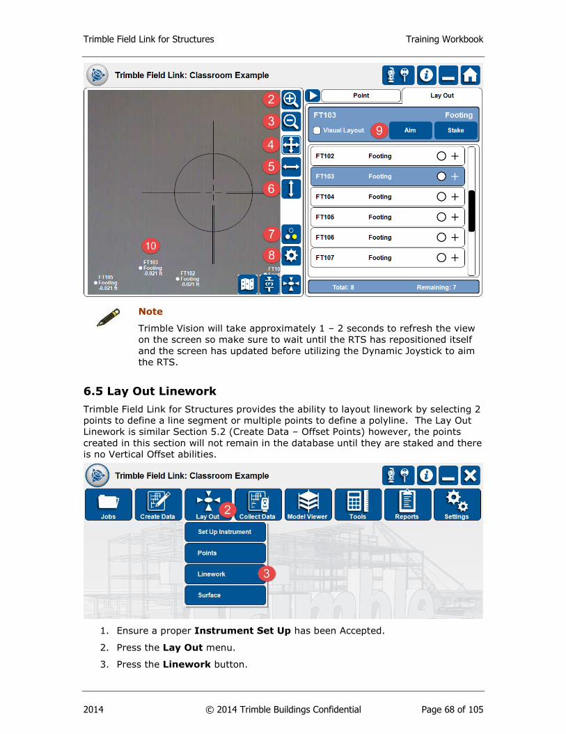
Trimble Field Link for Structures Training Workbook
2014 © 2014 Trimble Buildings Confidential Page 68 of 105
Note
Trimble Vision will take approximately 1 – 2 seconds to refresh the view
on the screen so make sure to wait until the RTS has repositioned itself
and the screen has updated before utilizing the Dynamic Joystick to aim
the RTS.
6.5 Lay Out Linework
Trimble Field Link for Structures provides the ability to layout linework by selecting 2
points to define a line segment or multiple points to define a polyline. The Lay Out
Linework is similar Section 5.2 (Create Data – Offset Points) however, the points
created in this section will not remain in the database until they are staked and there
is no Vertical Offset abilities.
1. Ensure a proper Instrument Set Up has been Accepted.
2. Press the Lay Out menu.
3. Press the Linework button.
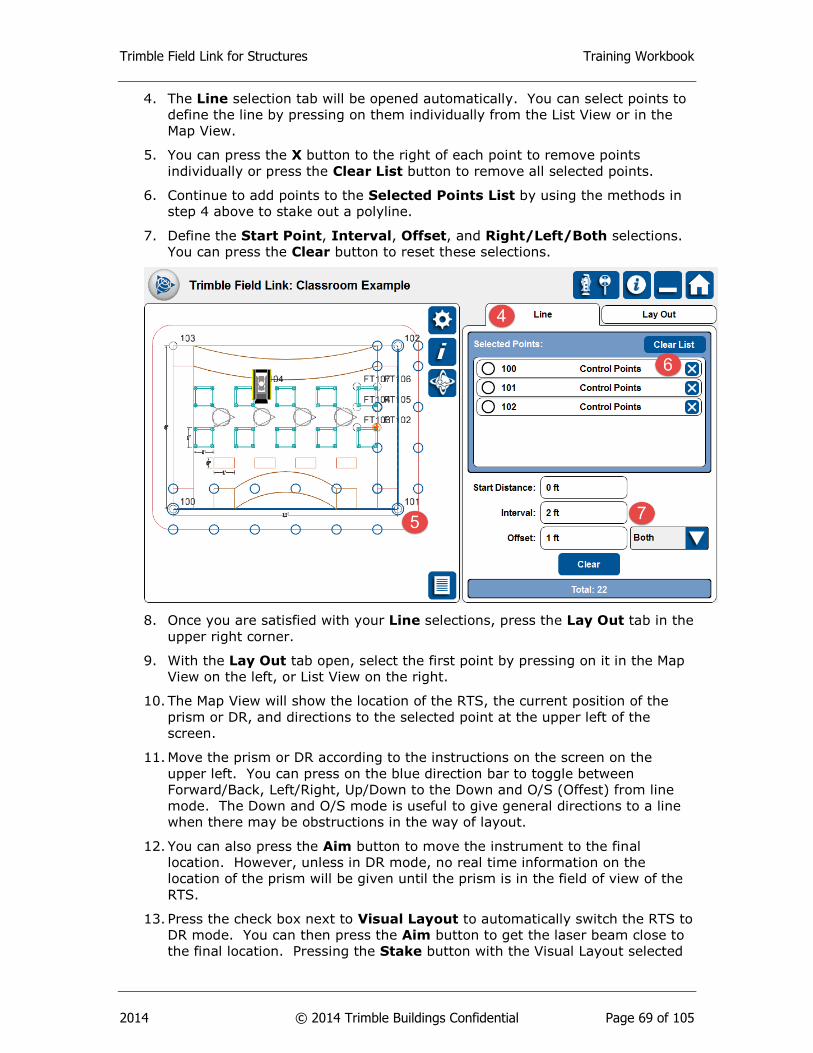
Trimble Field Link for Structures Training Workbook
2014 © 2014 Trimble Buildings Confidential Page 69 of 105
4. The Line selection tab will be opened automatically. You can select points to
define the line by pressing on them individually from the List View or in the
Map View.
5. You can press the X button to the right of each point to remove points
individually or press the Clear List button to remove all selected points.
6. Continue to add points to the Selected Points List by using the methods in
step 4 above to stake out a polyline.
7. Define the Start Point, Interval, Offset, and Right/Left/Both selections.
You can press the Clear button to reset these selections.
8. Once you are satisfied with your Line selections, press the Lay Out tab in the
upper right corner.
9. With the Lay Out tab open, select the first point by pressing on it in the Map
View on the left, or List View on the right.
10. The Map View will show the location of the RTS, the current position of the
prism or DR, and directions to the selected point at the upper left of the
screen.
11. Move the prism or DR according to the instructions on the screen on the
upper left. You can press on the blue direction bar to toggle between
Forward/Back, Left/Right, Up/Down to the Down and O/S (Offest) from line
mode. The Down and O/S mode is useful to give general directions to a line
when there may be obstructions in the way of layout.
12. You can also press the Aim button to move the instrument to the final
location. However, unless in DR mode, no real time information on the
location of the prism will be given until the prism is in the field of view of the
RTS.
13. Press the check box next to Visual Layout to automatically switch the RTS to
DR mode. You can then press the Aim button to get the laser beam close to
the final location. Pressing the Stake button with the Visual Layout selected
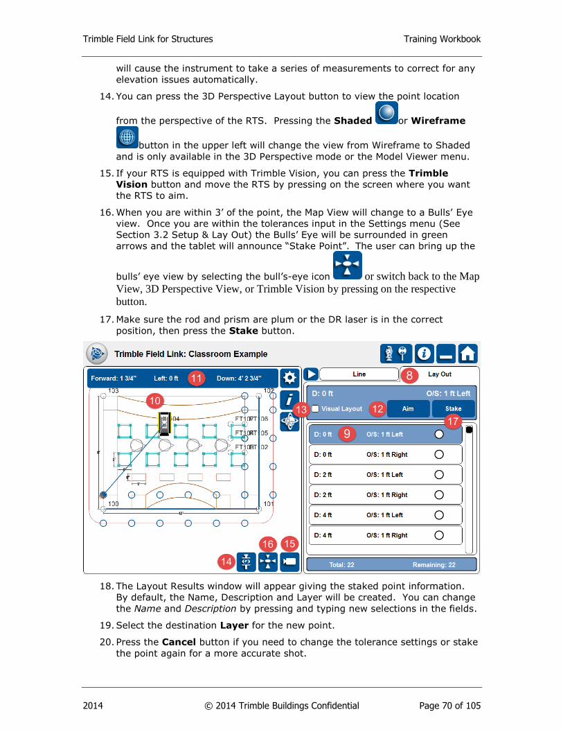
Trimble Field Link for Structures Training Workbook
2014 © 2014 Trimble Buildings Confidential Page 70 of 105
will cause the instrument to take a series of measurements to correct for any
elevation issues automatically.
14. You can press the 3D Perspective Layout button to view the point location
from the perspective of the RTS. Pressing the Shaded or Wireframe
button in the upper left will change the view from Wireframe to Shaded
and is only available in the 3D Perspective mode or the Model Viewer menu.
15. If your RTS is equipped with Trimble Vision, you can press the Trimble
Vision button and move the RTS by pressing on the screen where you want
the RTS to aim.
16. When you are within 3’ of the point, the Map View will change to a Bulls’ Eye
view. Once you are within the tolerances input in the Settings menu (See
Section 3.2 Setup & Lay Out) the Bulls’ Eye will be surrounded in green
arrows and the tablet will announce “Stake Point”. The user can bring up the
bulls’ eye view by selecting the bull’s-eye icon or switch back to the Map
View, 3D Perspective View, or Trimble Vision by pressing on the respective
button.
17. Make sure the rod and prism are plum or the DR laser is in the correct
position, then press the Stake button.
18. The Layout Results window will appear giving the staked point information.
By default, the Name, Description and Layer will be created. You can change
the Name and Description by pressing and typing new selections in the fields.
19. Select the destination Layer for the new point.
20. Press the Cancel button if you need to change the tolerance settings or stake
the point again for a more accurate shot.
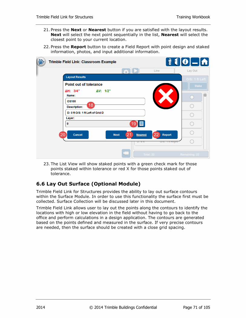
Trimble Field Link for Structures Training Workbook
2014 © 2014 Trimble Buildings Confidential Page 71 of 105
21. Press the Next or Nearest button if you are satisfied with the layout results.
Next will select the next point sequentially in the list, Nearest will select the
closest point to your current location.
22. Press the Report button to create a Field Report with point design and staked
information, photos, and input additional information.
23. The List View will show staked points with a green check mark for those
points staked within tolerance or red X for those points staked out of
tolerance.
6.6 Lay Out Surface (Optional Module)
Trimble Field Link for Structures provides the ability to lay out surface contours
within the Surface Module. In order to use this functionality the surface first must be
collected. Surface Collection will be discussed later in this document.
Trimble Field Link allows user to lay out the points along the contours to identify the
locations with high or low elevation in the field without having to go back to the
office and perform calculations in a design application. The contours are generated
based on the points defined and measured in the surface. If very precise contours
are needed, then the surface should be created with a close grid spacing.

Trimble Field Link for Structures Training Workbook
2014 © 2014 Trimble Buildings Confidential Page 72 of 105
1. Ensure a proper Instrument Set Up has been Accepted.
2. Press the Lay Out menu.
3. Press the Surface button.
4. The Surface selection tab will be opened automatically. You can select the
surface by pressing on it in the List View or on one of the surface boundaries
in the Map View.
5. Define an Elevation by typing the entry in the Elevation field, or using DR or
Prism mode to Shoot a reference elevation for the surface.
6. Enter a Tolerance for the surface to define High, In-Tolerance or Low points
and contours for the collected surface.
7. Once you are satisfied with your Surface settings, press the Lay Out tab in
the upper right corner.
8. With the Lay Out tab open, select the first point or contour by pressing on it
in the Map View.
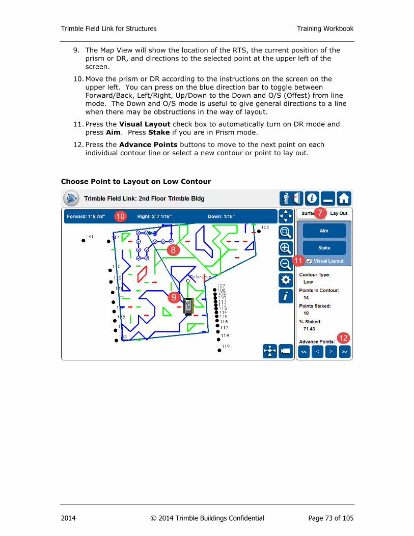
Trimble Field Link for Structures Training Workbook
2014 © 2014 Trimble Buildings Confidential Page 73 of 105
9. The Map View will show the location of the RTS, the current position of the
prism or DR, and directions to the selected point at the upper left of the
screen.
10. Move the prism or DR according to the instructions on the screen on the
upper left. You can press on the blue direction bar to toggle between
Forward/Back, Left/Right, Up/Down to the Down and O/S (Offest) from line
mode. The Down and O/S mode is useful to give general directions to a line
when there may be obstructions in the way of layout.
11. Press the Visual Layout check box to automatically turn on DR mode and
press Aim. Press Stake if you are in Prism mode.
12. Press the Advance Points buttons to move to the next point on each
individual contour line or select a new contour or point to lay out.
Choose Point to Layout on Low Contour
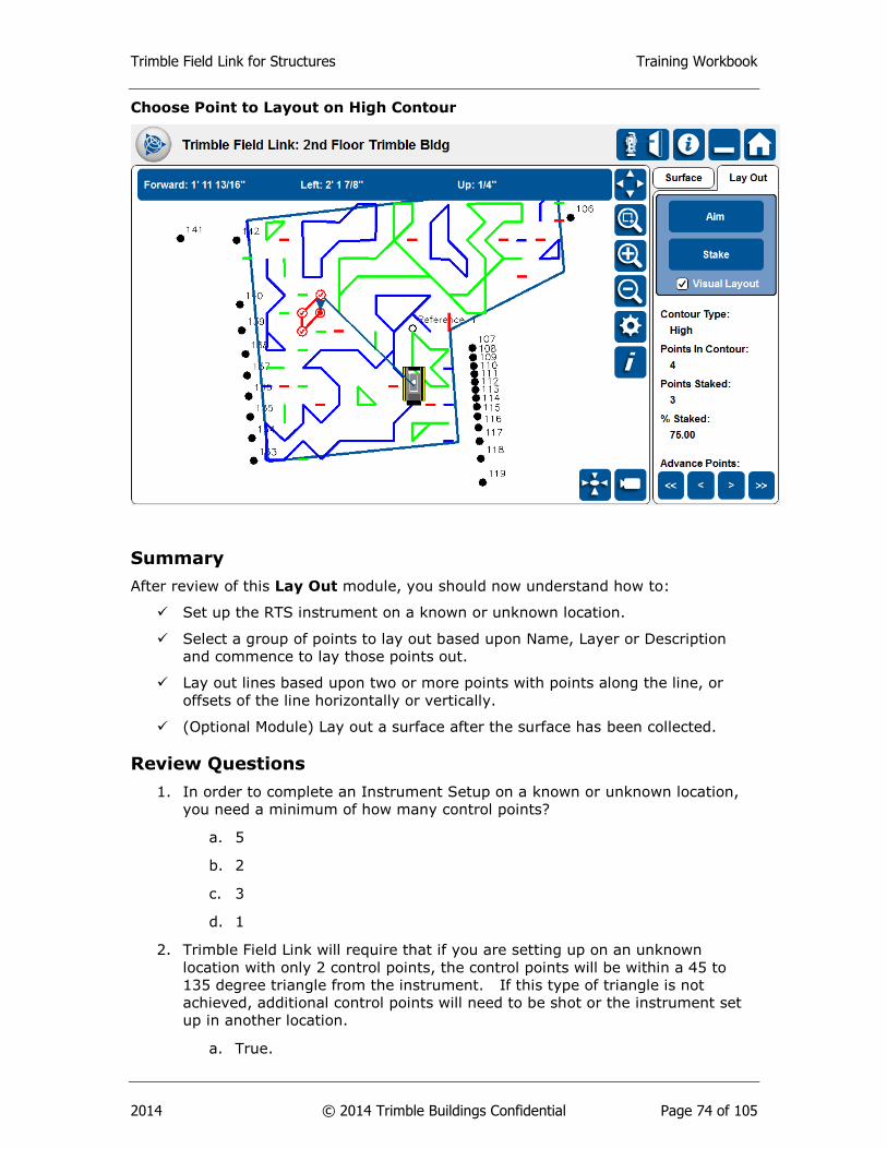
Trimble Field Link for Structures Training Workbook
2014 © 2014 Trimble Buildings Confidential Page 74 of 105
Choose Point to Layout on High Contour
Summary
After review of this Lay Out module, you should now understand how to:
Set up the RTS instrument on a known or unknown location.
Select a group of points to lay out based upon Name, Layer or Description
and commence to lay those points out.
Lay out lines based upon two or more points with points along the line, or
offsets of the line horizontally or vertically.
(Optional Module) Lay out a surface after the surface has been collected.
Review Questions
1. In order to complete an Instrument Setup on a known or unknown location,
you need a minimum of how many control points?
a. 5
b. 2
c. 3
d. 1
2. Trimble Field Link will require that if you are setting up on an unknown
location with only 2 control points, the control points will be within a 45 to
135 degree triangle from the instrument. If this type of triangle is not
achieved, additional control points will need to be shot or the instrument set
up in another location.
a. True.
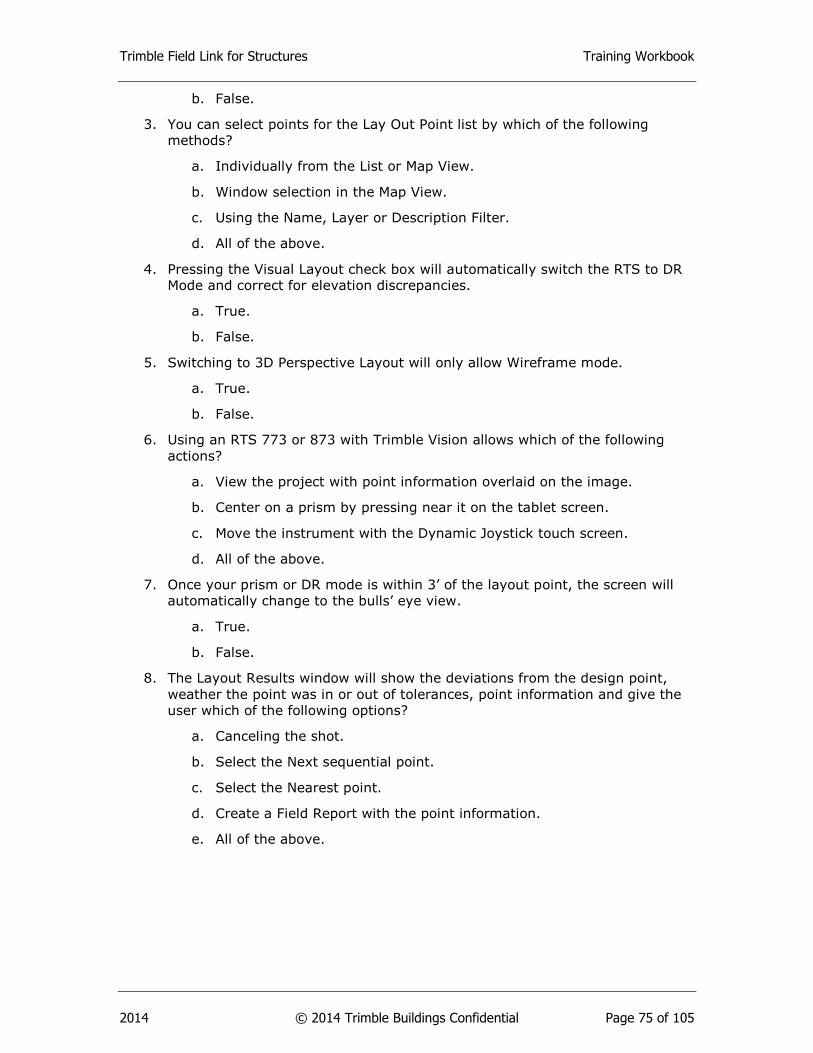
Trimble Field Link for Structures Training Workbook
2014 © 2014 Trimble Buildings Confidential Page 75 of 105
b. False.
3. You can select points for the Lay Out Point list by which of the following
methods?
a. Individually from the List or Map View.
b. Window selection in the Map View.
c. Using the Name, Layer or Description Filter.
d. All of the above.
4. Pressing the Visual Layout check box will automatically switch the RTS to DR
Mode and correct for elevation discrepancies.
a. True.
b. False.
5. Switching to 3D Perspective Layout will only allow Wireframe mode.
a. True.
b. False.
6. Using an RTS 773 or 873 with Trimble Vision allows which of the following
actions?
a. View the project with point information overlaid on the image.
b. Center on a prism by pressing near it on the tablet screen.
c. Move the instrument with the Dynamic Joystick touch screen.
d. All of the above.
7. Once your prism or DR mode is within 3’ of the layout point, the screen will
automatically change to the bulls’ eye view.
a. True.
b. False.
8. The Layout Results window will show the deviations from the design point,
weather the point was in or out of tolerances, point information and give the
user which of the following options?
a. Canceling the shot.
b. Select the Next sequential point.
c. Select the Nearest point.
d. Create a Field Report with the point information.
e. All of the above.
Trimble Field Link for Structures Training Workbook
2014 © 2014 Trimble Buildings Confidential Page 76 of 105
9. In order to stake a line or polyline, you must define which of the following
information?
a. Start Point.
b. Interval distance.
c. Offset distance.
d. All of the above.
10. While laying out linework, you can toggle the direction bar between
Forward/Back/Left/Right to Down and Out by pressing the blue bar.
a. True.
b. False.
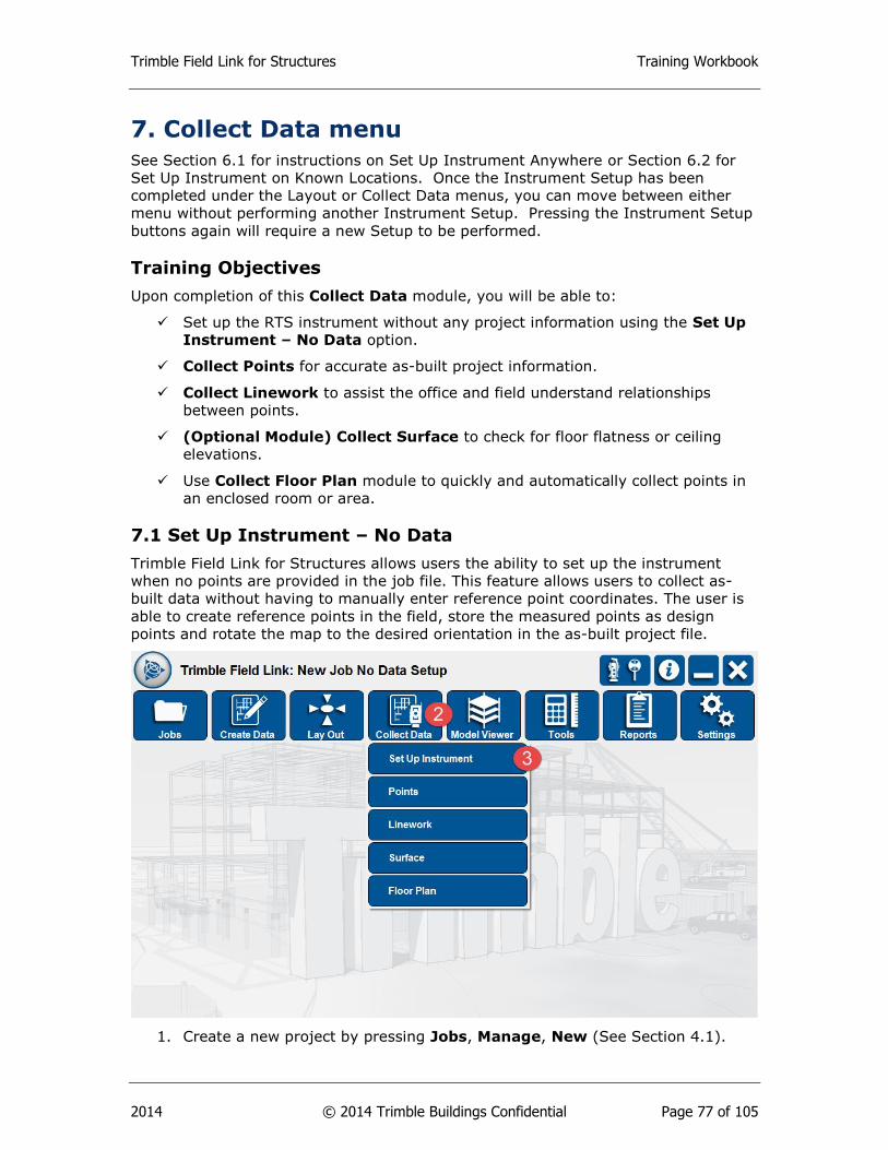
Trimble Field Link for Structures Training Workbook
2014 © 2014 Trimble Buildings Confidential Page 77 of 105
7. Collect Data menu
See Section 6.1 for instructions on Set Up Instrument Anywhere or Section 6.2 for
Set Up Instrument on Known Locations. Once the Instrument Setup has been
completed under the Layout or Collect Data menus, you can move between either
menu without performing another Instrument Setup. Pressing the Instrument Setup
buttons again will require a new Setup to be performed.
Training Objectives
Upon completion of this Collect Data module, you will be able to:
Set up the RTS instrument without any project information using the Set Up
Instrument – No Data option.
Collect Points for accurate as-built project information.
Collect Linework to assist the office and field understand relationships
between points.
(Optional Module) Collect Surface to check for floor flatness or ceiling
elevations.
Use Collect Floor Plan module to quickly and automatically collect points in
an enclosed room or area.
7.1 Set Up Instrument – No Data
Trimble Field Link for Structures allows users the ability to set up the instrument
when no points are provided in the job file. This feature allows users to collect as-
built data without having to manually enter reference point coordinates. The user is
able to create reference points in the field, store the measured points as design
points and rotate the map to the desired orientation in the as-built project file.
1. Create a new project by pressing Jobs, Manage, New (See Section 4.1).
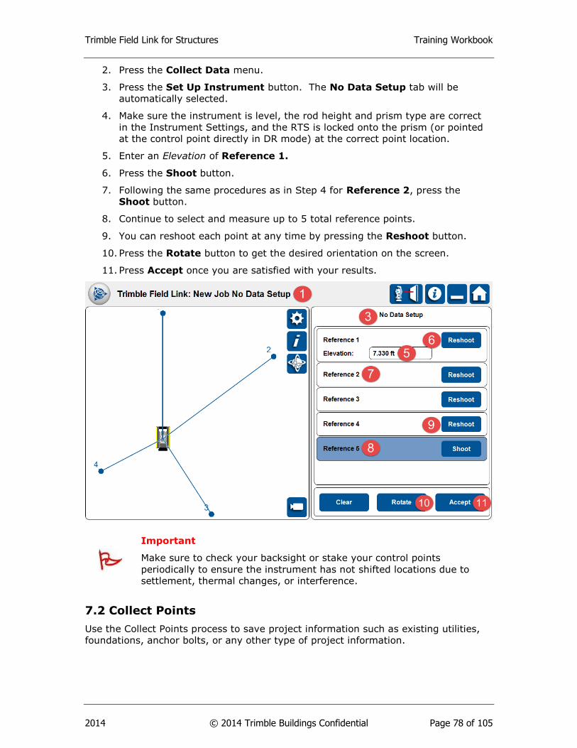
Trimble Field Link for Structures Training Workbook
2014 © 2014 Trimble Buildings Confidential Page 78 of 105
2. Press the Collect Data menu.
3. Press the Set Up Instrument button. The No Data Setup tab will be
automatically selected.
4. Make sure the instrument is level, the rod height and prism type are correct
in the Instrument Settings, and the RTS is locked onto the prism (or pointed
at the control point directly in DR mode) at the correct point location.
5. Enter an Elevation of Reference 1.
6. Press the Shoot button.
7. Following the same procedures as in Step 4 for Reference 2, press the
Shoot button.
8. Continue to select and measure up to 5 total reference points.
9. You can reshoot each point at any time by pressing the Reshoot button.
10. Press the Rotate button to get the desired orientation on the screen.
11. Press Accept once you are satisfied with your results.
Important
Make sure to check your backsight or stake your control points
periodically to ensure the instrument has not shifted locations due to
settlement, thermal changes, or interference.
7.2 Collect Points
Use the Collect Points process to save project information such as existing utilities,
foundations, anchor bolts, or any other type of project information.
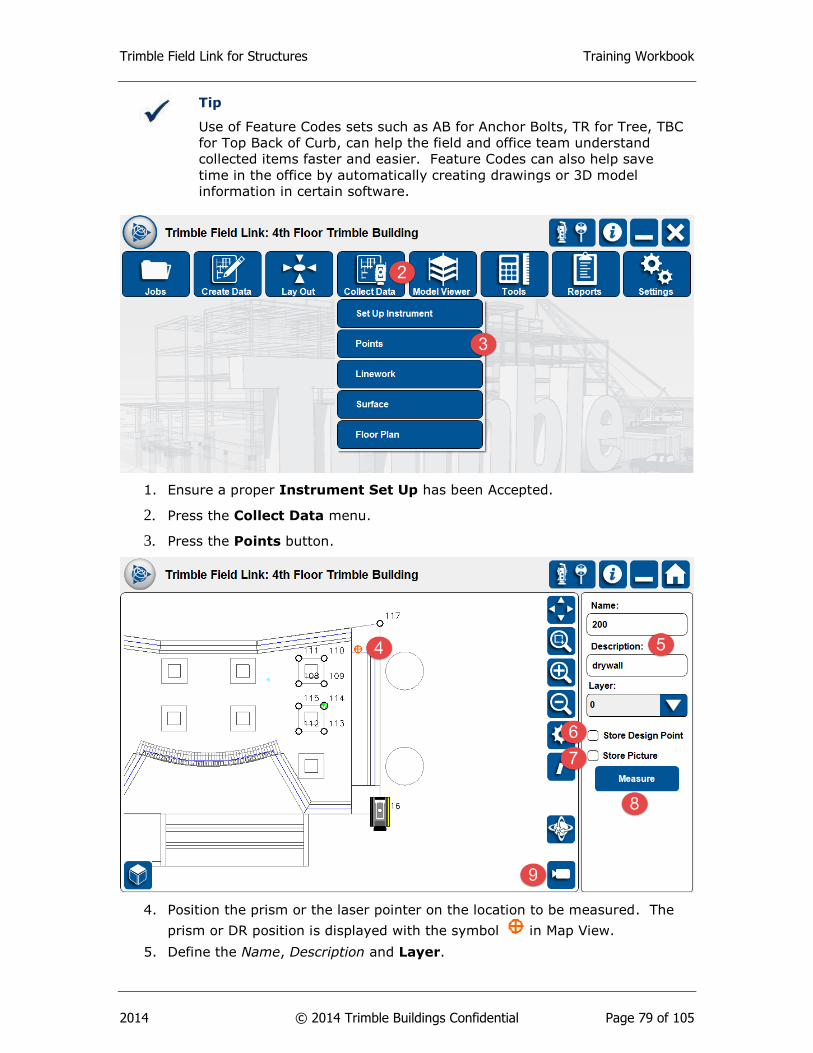
Trimble Field Link for Structures Training Workbook
2014 © 2014 Trimble Buildings Confidential Page 79 of 105
Tip
Use of Feature Codes sets such as AB for Anchor Bolts, TR for Tree, TBC
for Top Back of Curb, can help the field and office team understand
collected items faster and easier. Feature Codes can also help save
time in the office by automatically creating drawings or 3D model
information in certain software.
1. Ensure a proper Instrument Set Up has been Accepted.
2. Press the Collect Data menu.
3. Press the Points button.
4. Position the prism or the laser pointer on the location to be measured. The
prism or DR position is displayed with the symbol in Map View.
5. Define the Name, Description and Layer.
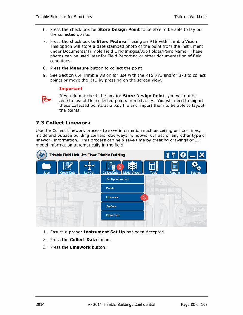
Trimble Field Link for Structures Training Workbook
2014 © 2014 Trimble Buildings Confidential Page 80 of 105
6. Press the check box for Store Design Point to be able to be able to lay out
the collected points.
7. Press the check box to Store Picture if using an RTS with Trimble Vision.
This option will store a date stamped photo of the point from the instrument
under Documents/Trimble Field Link/Images/Job Folder/Point Name. These
photos can be used later for Field Reporting or other documentation of field
conditions.
8. Press the Measure button to collect the point.
9. See Section 6.4 Trimble Vision for use with the RTS 773 and/or 873 to collect
points or move the RTS by pressing on the screen view.
Important
If you do not check the box for Store Design Point, you will not be
able to layout the collected points immediately. You will need to export
these collected points as a .csv file and import them to be able to layout
the points.
7.3 Collect Linework
Use the Collect Linework process to save information such as ceiling or floor lines,
inside and outside building corners, doorways, windows, utilities or any other type of
linework information. This process can help save time by creating drawings or 3D
model information automatically in the field.
1. Ensure a proper Instrument Set Up has been Accepted.
2. Press the Collect Data menu.
3. Press the Linework button.
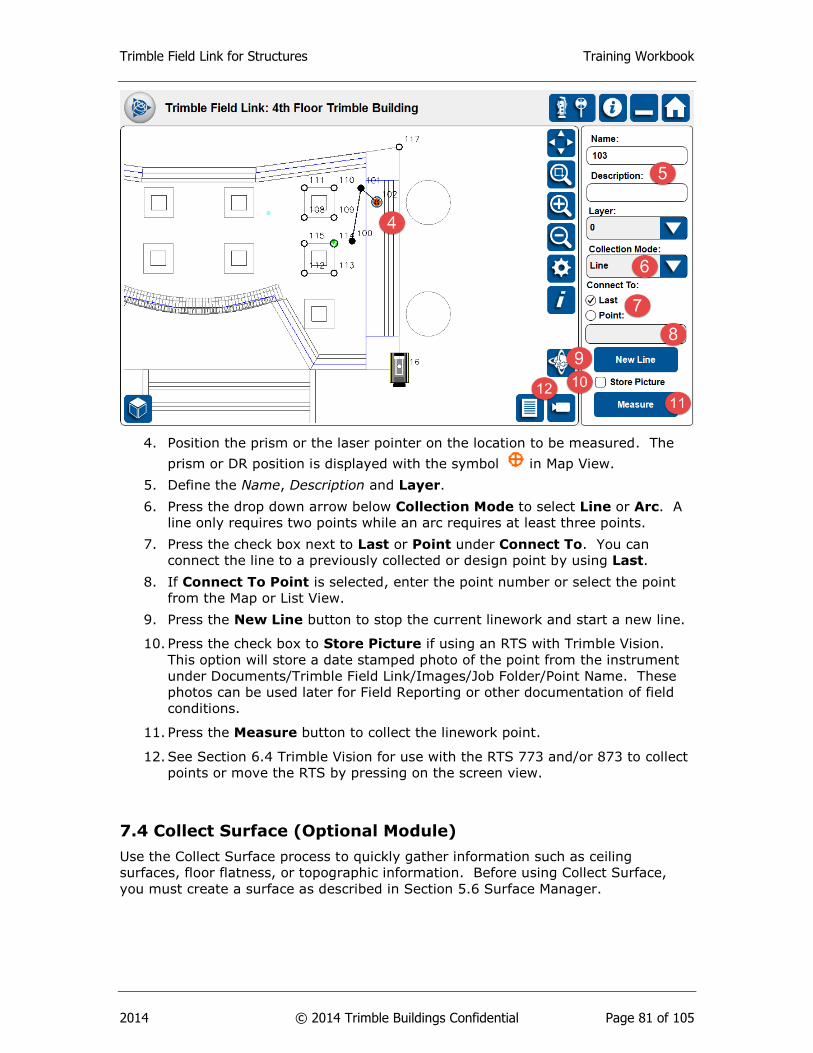
Trimble Field Link for Structures Training Workbook
2014 © 2014 Trimble Buildings Confidential Page 81 of 105
4. Position the prism or the laser pointer on the location to be measured. The
prism or DR position is displayed with the symbol in Map View.
5. Define the Name, Description and Layer.
6. Press the drop down arrow below Collection Mode to select Line or Arc. A
line only requires two points while an arc requires at least three points.
7. Press the check box next to Last or Point under Connect To. You can
connect the line to a previously collected or design point by using Last.
8. If Connect To Point is selected, enter the point number or select the point
from the Map or List View.
9. Press the New Line button to stop the current linework and start a new line.
10. Press the check box to Store Picture if using an RTS with Trimble Vision.
This option will store a date stamped photo of the point from the instrument
under Documents/Trimble Field Link/Images/Job Folder/Point Name. These
photos can be used later for Field Reporting or other documentation of field
conditions.
11. Press the Measure button to collect the linework point.
12. See Section 6.4 Trimble Vision for use with the RTS 773 and/or 873 to collect
points or move the RTS by pressing on the screen view.
7.4 Collect Surface (Optional Module)
Use the Collect Surface process to quickly gather information such as ceiling
surfaces, floor flatness, or topographic information. Before using Collect Surface,
you must create a surface as described in Section 5.6 Surface Manager.
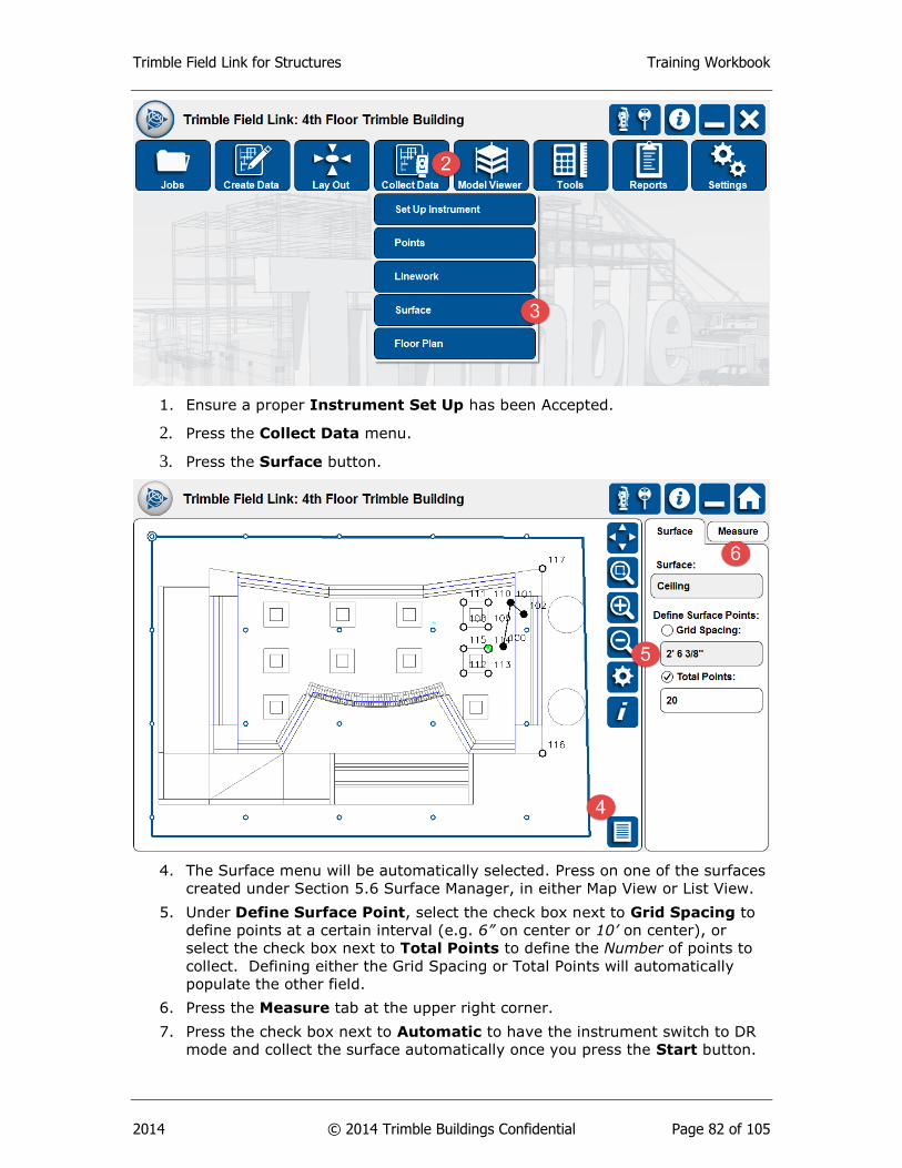
Trimble Field Link for Structures Training Workbook
2014 © 2014 Trimble Buildings Confidential Page 82 of 105
1. Ensure a proper Instrument Set Up has been Accepted.
2. Press the Collect Data menu.
3. Press the Surface button.
4. The Surface menu will be automatically selected. Press on one of the surfaces
created under Section 5.6 Surface Manager, in either Map View or List View.
5. Under Define Surface Point, select the check box next to Grid Spacing to
define points at a certain interval (e.g. 6” on center or 10’ on center), or
select the check box next to Total Points to define the Number of points to
collect. Defining either the Grid Spacing or Total Points will automatically
populate the other field.
6. Press the Measure tab at the upper right corner.
7. Press the check box next to Automatic to have the instrument switch to DR
mode and collect the surface automatically once you press the Start button.

Trimble Field Link for Structures Training Workbook
2014 © 2014 Trimble Buildings Confidential Page 83 of 105
8. If you do not check the box next to Automatic, position the prism or the
laser pointer according to the directions at the top of the screen on the
location to be measured. The prism or DR position is displayed with the
symbol . Press the Measure button for each surface point.
9. The number of points and percentage status of the surface collection will be
displayed next to Measured, Skipped, and Remaining on the right. Once
the process is complete
10. The surface collection will be complete when Measured shows 100%. Any
points skipped during the collection process due to obstructions, major
elevation changes, or reflectivity, will be shown on the Map View as Red X’s.
11. You may need to move the instrument to collect remaining points in manual
mode or disregard these points.
12. Once complete, go to Surface Report (Section 10.4) to set the reference
elevation and tolerances, show calculations of high and low areas, volumes,
contour lines and other surface data.

Trimble Field Link for Structures Training Workbook
2014 © 2014 Trimble Buildings Confidential Page 84 of 105
7.4 Collect Floor Plan
Collecting a floor plan is an automated routine utilizing DR Mode to collect the
footprint of a room or enclosed area without manually pointing and shooting the
instrument. The instrument will shoot 50, 100, 200 or 400 points at equal degrees
along the horizontal plane to produce rough outlines of the project.
1. Ensure a proper Instrument Set Up has been Accepted.
2. Press the Collect Data menu.
3. Press the Floor Plan button. The instrument will automatically revert to the
DR Mode.
4. Define the Name, Description, and Layer for the first point.
5. Press the dropdown arrow below Points to define the total number of points
to be collected (options are 50, 100, 200 or 400). The collection time for the
number of points selected will show at the bottom right of the screen.
6. If necessary, check the box next to Distance Range and input the Minimum
and Maximum distances to be recorded.

Trimble Field Link for Structures Training Workbook
2014 © 2014 Trimble Buildings Confidential Page 85 of 105
7. Press the Start button. A window will appear showing the status of point
collection until completed.
8. Once complete, the points will show on the Map View and each point will be
stored for later export.
Summary
After review of this Collect Data module, you should now understand how to:
Set up the RTS instrument without any project information using the Set Up
Instrument – No Data option.
Collect Points for accurate as-built project information.
Collect Linework to assist the office and field understand relationships
between points.
(Optional Module) Collect Surface to check for floor flatness or ceiling
elevations.
Trimble Field Link for Structures Training Workbook
2014 © 2014 Trimble Buildings Confidential Page 86 of 105
Use Collect Floor Plan module to quickly and automatically collect points in
an enclosed room or area.
Review Questions
1. No Data Setup allows the user to setup the instrument only if there is existing
model data.
a. True.
b. False.
2. Which of the following items must be defined before a point can be collected?
a. Name.
b. Description.
c. Layer.
d. Photo.
3. You must check the Store Design Point box to be able to lay out the points
without exporting them if collected under Collect Data menu.
a. True.
b. False.
4. Under Collect Linework, you can collect all of the following items except:
a. Lines.
b. Arcs.
c. Photos.
d. Surfaces.
5. Under Collect Linework, you can make continuous lines by using the check
box next to Last or Point and defining the point to connect to.
a. True.
b. False.
6. The Collect Surface optional module will allow for the automatic or manual
collection of points for which of the following?
a. Ceilings.
b. Floors.
c. At specified grid spacing.
d. All of the above.
Trimble Field Link for Structures Training Workbook
2014 © 2014 Trimble Buildings Confidential Page 87 of 105
7. The Collect Floor Plan module allows for the automatic collection of how many
horizontal points around the Robotic Total Station?
a. 50.
b. 100.
c. 200.
d. 400.
e. All of the above.
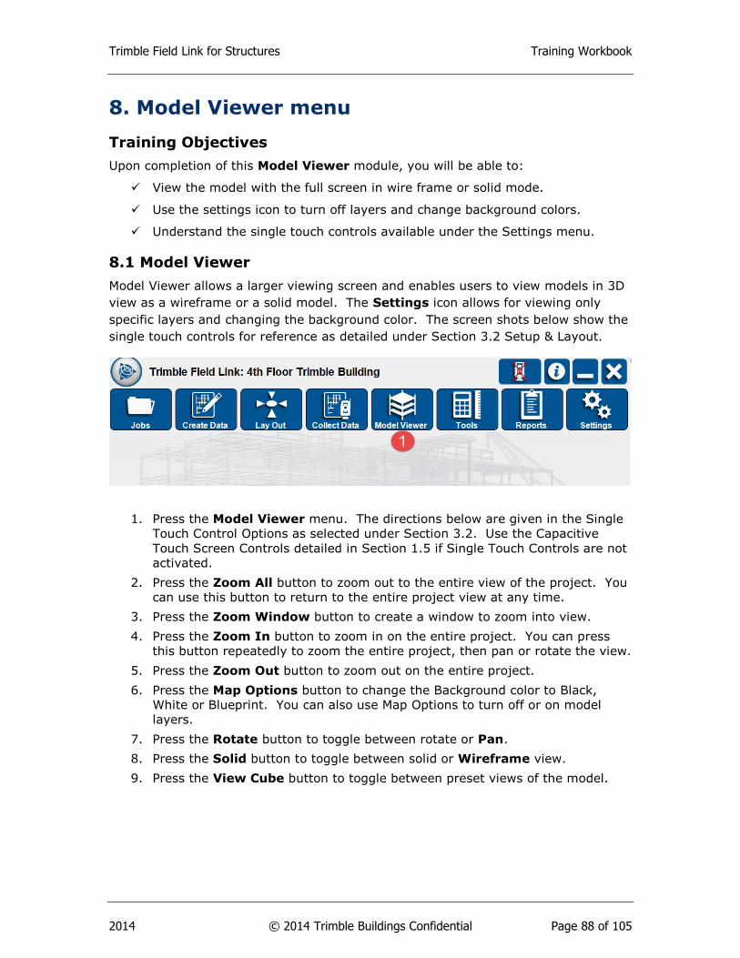
Trimble Field Link for Structures Training Workbook
2014 © 2014 Trimble Buildings Confidential Page 88 of 105
8. Model Viewer menu
Training Objectives
Upon completion of this Model Viewer module, you will be able to:
View the model with the full screen in wire frame or solid mode.
Use the settings icon to turn off layers and change background colors.
Understand the single touch controls available under the Settings menu.
8.1 Model Viewer
Model Viewer allows a larger viewing screen and enables users to view models in 3D
view as a wireframe or a solid model. The Settings icon allows for viewing only
specific layers and changing the background color. The screen shots below show the
single touch controls for reference as detailed under Section 3.2 Setup & Layout.
1. Press the Model Viewer menu. The directions below are given in the Single
Touch Control Options as selected under Section 3.2. Use the Capacitive
Touch Screen Controls detailed in Section 1.5 if Single Touch Controls are not
activated.
2. Press the Zoom All button to zoom out to the entire view of the project. You
can use this button to return to the entire project view at any time.
3. Press the Zoom Window button to create a window to zoom into view.
4. Press the Zoom In button to zoom in on the entire project. You can press
this button repeatedly to zoom the entire project, then pan or rotate the view.
5. Press the Zoom Out button to zoom out on the entire project.
6. Press the Map Options button to change the Background color to Black,
White or Blueprint. You can also use Map Options to turn off or on model
layers.
7. Press the Rotate button to toggle between rotate or Pan.
8. Press the Solid button to toggle between solid or Wireframe view.
9. Press the View Cube button to toggle between preset views of the model.
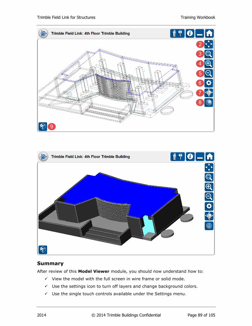
Trimble Field Link for Structures Training Workbook
2014 © 2014 Trimble Buildings Confidential Page 89 of 105
Summary
After review of this Model Viewer module, you should now understand how to:
View the model with the full screen in wire frame or solid mode.
Use the settings icon to turn off layers and change background colors.
Use the single touch controls available under the Settings menu.

Trimble Field Link for Structures Training Workbook
2014 © 2014 Trimble Buildings Confidential Page 90 of 105
Review Questions
1. The Model Viewer menu allows for the viewing of point information including
Name, Description, Elevation and Layers.
a. True.
b. False.
2. Which of the following viewing modes are available in the Model Viewer?
a. Trimble Vision.
b. Bulls’ eye.
c. Solid.
d. Point List View.
3. Single touch controls are only available under the Model Viewer.
a. True.
b. False.
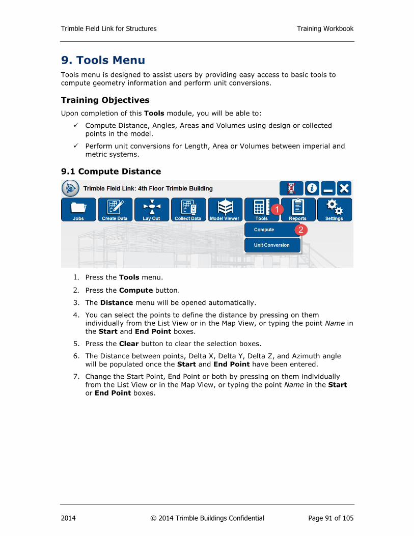
Trimble Field Link for Structures Training Workbook
2014 © 2014 Trimble Buildings Confidential Page 91 of 105
9. Tools Menu
Tools menu is designed to assist users by providing easy access to basic tools to
compute geometry information and perform unit conversions.
Training Objectives
Upon completion of this Tools module, you will be able to:
Compute Distance, Angles, Areas and Volumes using design or collected
points in the model.
Perform unit conversions for Length, Area or Volumes between imperial and
metric systems.
9.1 Compute Distance
1. Press the Tools menu.
2. Press the Compute button.
3. The Distance menu will be opened automatically.
4. You can select the points to define the distance by pressing on them
individually from the List View or in the Map View, or typing the point Name in
the Start and End Point boxes.
5. Press the Clear button to clear the selection boxes.
6. The Distance between points, Delta X, Delta Y, Delta Z, and Azimuth angle
will be populated once the Start and End Point have been entered.
7. Change the Start Point, End Point or both by pressing on them individually
from the List View or in the Map View, or typing the point Name in the Start
or End Point boxes.
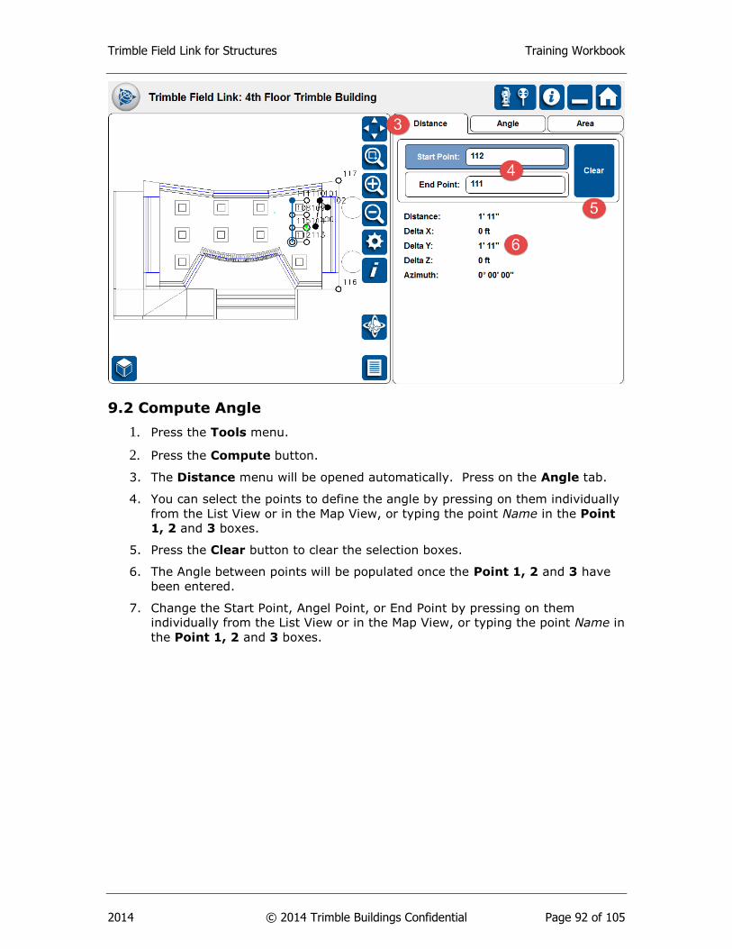
Trimble Field Link for Structures Training Workbook
2014 © 2014 Trimble Buildings Confidential Page 92 of 105
9.2 Compute Angle
1. Press the Tools menu.
2. Press the Compute button.
3. The Distance menu will be opened automatically. Press on the Angle tab.
4. You can select the points to define the angle by pressing on them individually
from the List View or in the Map View, or typing the point Name in the Point
1, 2 and 3 boxes.
5. Press the Clear button to clear the selection boxes.
6. The Angle between points will be populated once the Point 1, 2 and 3 have
been entered.
7. Change the Start Point, Angel Point, or End Point by pressing on them
individually from the List View or in the Map View, or typing the point Name in
the Point 1, 2 and 3 boxes.

Trimble Field Link for Structures Training Workbook
2014 © 2014 Trimble Buildings Confidential Page 93 of 105
9.3 Compute Area & Volume
1. Press the Tools menu.
2. Press the Compute button.
3. The Distance menu will be opened automatically. Press on the Area tab.
4. You can select the points to define the Area by pressing on them individually
from the List View or in the Map View.
5. You must select a minimum of 3 points and select the beginning point to
create a boundary around the area.
6. Once the boundary around the area has been defined, the Perimeter and Area
will be populated.
7. Enter the Depth to automatically calculate the volume of the area.
8. Press the Reset button to calculate a new Area or Volume.
9. Press the Undo button to unselect the last point entry.
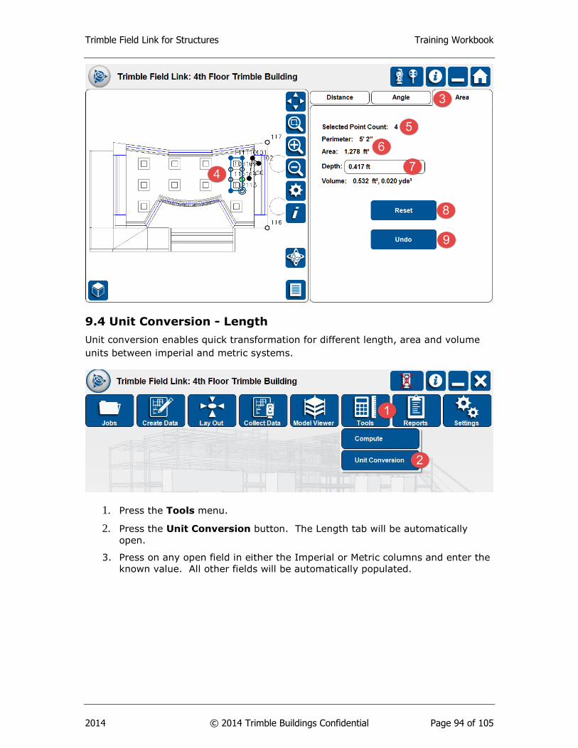
Trimble Field Link for Structures Training Workbook
2014 © 2014 Trimble Buildings Confidential Page 94 of 105
9.4 Unit Conversion - Length
Unit conversion enables quick transformation for different length, area and volume
units between imperial and metric systems.
1. Press the Tools menu.
2. Press the Unit Conversion button. The Length tab will be automatically
open.
3. Press on any open field in either the Imperial or Metric columns and enter the
known value. All other fields will be automatically populated.
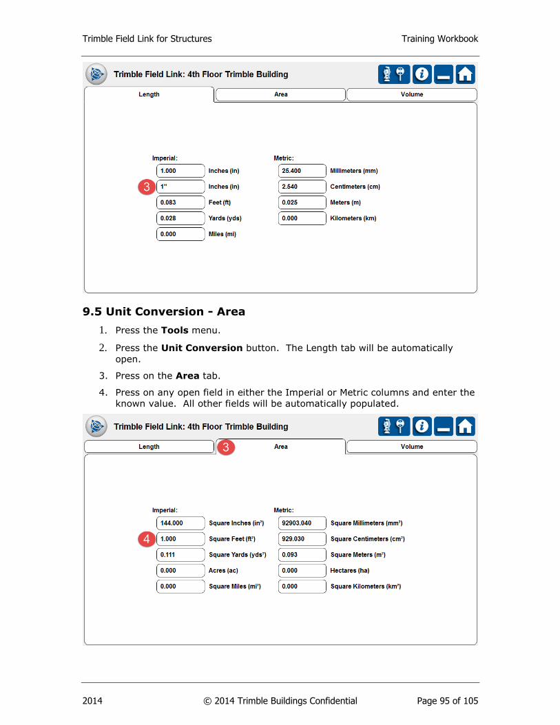
Trimble Field Link for Structures Training Workbook
2014 © 2014 Trimble Buildings Confidential Page 95 of 105
9.5 Unit Conversion - Area
1. Press the Tools menu.
2. Press the Unit Conversion button. The Length tab will be automatically
open.
3. Press on the Area tab.
4. Press on any open field in either the Imperial or Metric columns and enter the
known value. All other fields will be automatically populated.
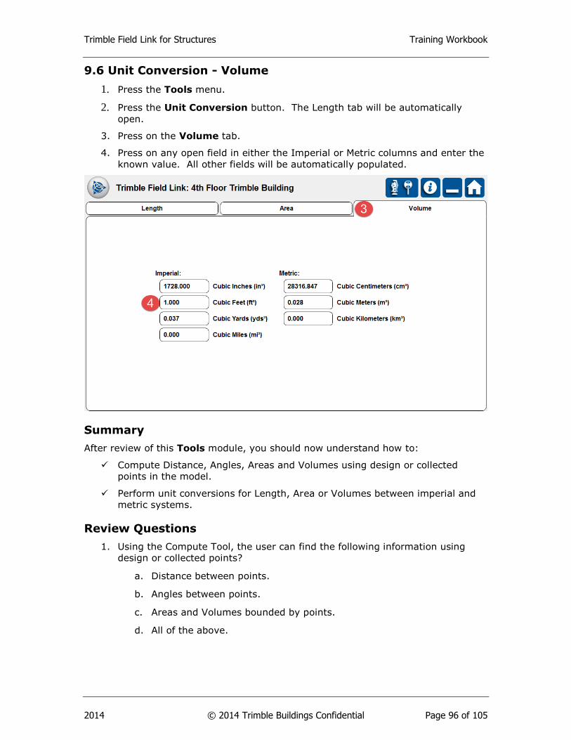
Trimble Field Link for Structures Training Workbook
2014 © 2014 Trimble Buildings Confidential Page 96 of 105
9.6 Unit Conversion - Volume
1. Press the Tools menu.
2. Press the Unit Conversion button. The Length tab will be automatically
open.
3. Press on the Volume tab.
4. Press on any open field in either the Imperial or Metric columns and enter the
known value. All other fields will be automatically populated.
Summary
After review of this Tools module, you should now understand how to:
Compute Distance, Angles, Areas and Volumes using design or collected
points in the model.
Perform unit conversions for Length, Area or Volumes between imperial and
metric systems.
Review Questions
1. Using the Compute Tool, the user can find the following information using
design or collected points?
a. Distance between points.
b. Angles between points.
c. Areas and Volumes bounded by points.
d. All of the above.

Trimble Field Link for Structures Training Workbook
2014 © 2014 Trimble Buildings Confidential Page 97 of 105
2. Volumes will be automatically calculated after enclosing an area by picking
points?
a. True.
b. False.
3. Which of the following can be found under the Unit Conversion Tool to
translate between Imperial and Metric?
a. Length.
b. Area.
c. Volume.
d. All of the above.
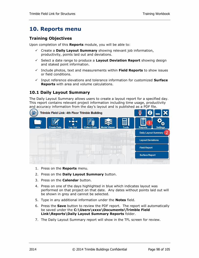
Trimble Field Link for Structures Training Workbook
2014 © 2014 Trimble Buildings Confidential Page 98 of 105
10. Reports menu
Training Objectives
Upon completion of this Reports module, you will be able to:
Create a Daily Layout Summary showing relevant job information,
productivity, points laid out and deviations.
Select a date range to produce a Layout Deviation Report showing design
and staked point information.
Include photos, text and measurements within Field Reports to show issues
or field conditions.
Input reference elevations and tolerance information for customized Surface
Reports with area and volume calculations.
10.1 Daily Layout Summary
The Daily Layout Summary allows users to create a layout report for a specified day.
This report contains relevant project information including time usage, productivity
and accuracy information from the day’s layout and is published as a PDF file.
1. Press on the Reports menu.
2. Press on the Daily Layout Summary button.
3. Press on the Calendar button.
4. Press on one of the days highlighted in blue which indicates layout was
performed on that project on that date. Any dates without points laid out will
be shown in grey and cannot be selected.
5. Type in any additional information under the Notes field.
6. Press the Save button to review the PDF report. The report will automatically
be saved under the C:\Users\xxxx\Documents\Trimble Field
Link\Reports\Daily Layout Summary Reports folder.
7. The Daily Layout Summary report will show in the TFL screen for review.
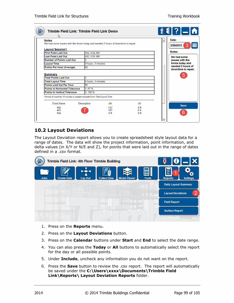
Trimble Field Link for Structures Training Workbook
2014 © 2014 Trimble Buildings Confidential Page 99 of 105
10.2 Layout Deviations
The Layout Deviation report allows you to create spreadsheet style layout data for a
range of dates. The data will show the project information, point information, and
delta values (in X/Y or N/E and Z), for points that were laid out in the range of dates
defined in a .csv format.
1. Press on the Reports menu.
2. Press on the Layout Deviations button.
3. Press on the Calendar buttons under Start and End to select the date range.
4. You can also press the Today or All buttons to automatically select the report
for the day or all possible points.
5. Under Include, uncheck any information you do not want on the report.
6. Press the Save button to review the .csv report. The report will automatically
be saved under the C:\Users\xxxx\Documents\Trimble Field
Link\Reports\ Layout Deviation Reports folder.
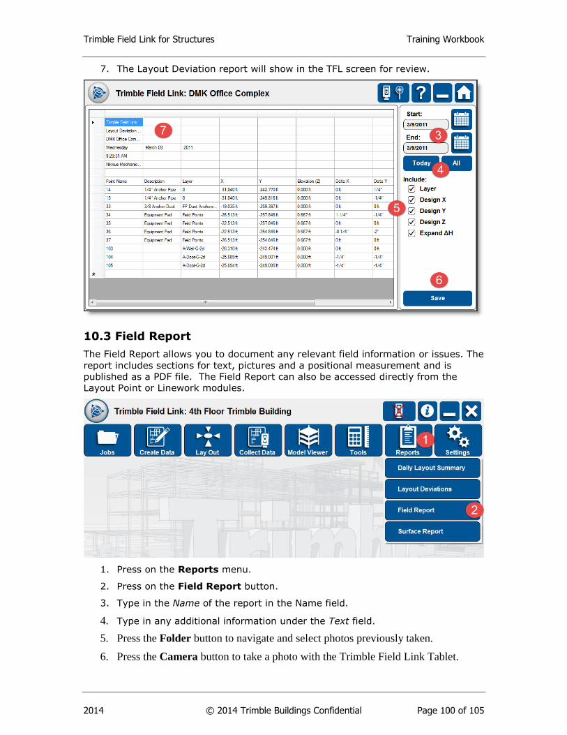
Trimble Field Link for Structures Training Workbook
2014 © 2014 Trimble Buildings Confidential Page 100 of 105
7. The Layout Deviation report will show in the TFL screen for review.
10.3 Field Report
The Field Report allows you to document any relevant field information or issues. The
report includes sections for text, pictures and a positional measurement and is
published as a PDF file. The Field Report can also be accessed directly from the
Layout Point or Linework modules.
1. Press on the Reports menu.
2. Press on the Field Report button.
3. Type in the Name of the report in the Name field.
4. Type in any additional information under the Text field.
5. Press the Folder button to navigate and select photos previously taken.
6. Press the Camera button to take a photo with the Trimble Field Link Tablet.
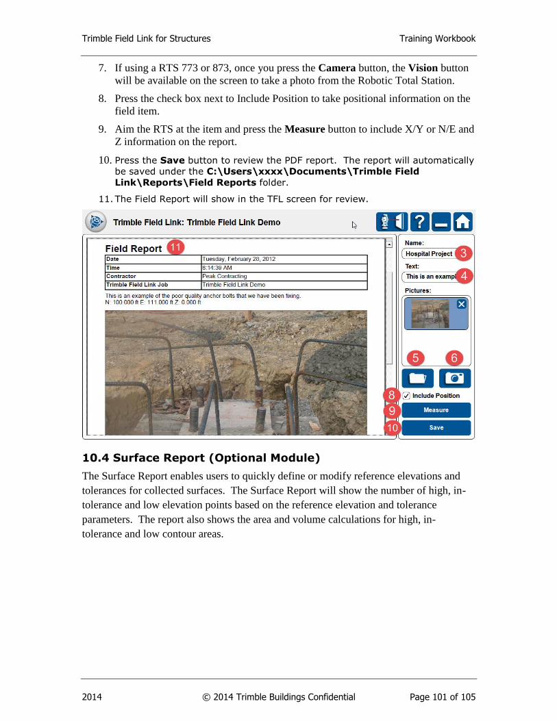
Trimble Field Link for Structures Training Workbook
2014 © 2014 Trimble Buildings Confidential Page 101 of 105
7. If using a RTS 773 or 873, once you press the Camera button, the Vision button
will be available on the screen to take a photo from the Robotic Total Station.
8. Press the check box next to Include Position to take positional information on the
field item.
9. Aim the RTS at the item and press the Measure button to include X/Y or N/E and
Z information on the report.
10. Press the Save button to review the PDF report. The report will automatically
be saved under the C:\Users\xxxx\Documents\Trimble Field
Link\Reports\Field Reports folder.
11. The Field Report will show in the TFL screen for review.
10.4 Surface Report (Optional Module)
The Surface Report enables users to quickly define or modify reference elevations and
tolerances for collected surfaces. The Surface Report will show the number of high, in-
tolerance and low elevation points based on the reference elevation and tolerance
parameters. The report also shows the area and volume calculations for high, in-
tolerance and low contour areas.
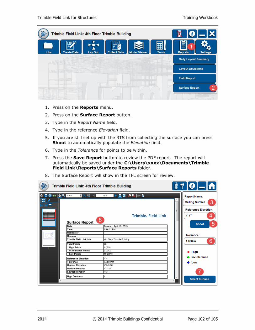
Trimble Field Link for Structures Training Workbook
2014 © 2014 Trimble Buildings Confidential Page 102 of 105
1. Press on the Reports menu.
2. Press on the Surface Report button.
3. Type in the Report Name field.
4. Type in the reference Elevation field.
5. If you are still set up with the RTS from collecting the surface you can press
Shoot to automatically populate the Elevation field.
6. Type in the Tolerance for points to be within.
7. Press the Save Report button to review the PDF report. The report will
automatically be saved under the C:\Users\xxxx\Documents\Trimble
Field Link\Reports\Surface Reports folder.
8. The Surface Report will show in the TFL screen for review.
Trimble Field Link for Structures Training Workbook
2014 © 2014 Trimble Buildings Confidential Page 103 of 105
Summary
After review of this Reports module, you should now understand how to:
Create a Daily Layout Summary showing relevant job information,
productivity, points laid out and deviations.
Select a date range to produce a Layout Deviation Report showing design
and staked point information.
Include photos, text and measurements within Field Reports to show issues
or field conditions.
Input reference elevations and tolerance information for customized Surface
Reports with area and volume calculations.
Review Questions
1. You can create a Daily Layout Summary for dates when no points have been
staked?
a. True.
b. False.
2. The Layout Deviation Report will save out which type of file?
a. .pdf
b. .tfl
c. .csv
d. All of the above.
3. The Field Report can contain which type of information?
a. Text.
b. Photos.
c. Measurements.
d. All of the above.
4. Each type of Report is automatically created and placed within a specific
reports folder under C:\Users\xxxx\Documents\Trimble Field Link\Reports.
a. True
b. False
5. The Surface Report requires which of the following prior to creating an
accurate report of the surface?
a. Reference elevation.
b. Tolerance.
c. Collected surface points.
d. All of the above.