Embed Size (px)
Citation preview
Trigger-Less Readout of the PANDA Electromagnetic
Calorimeter
M. Kavatsyuk, H. Löhner, J.G. Messchendorp,H. Moeini, G. Tambave
for the PANDA collaborationKVI, University of Groningen, Groningen, The Netherlands
● PANDA EMC
● Readout concept
● Synchronous optical-link connection
● SADC-based Intelligent Front-End
● Data CollectionHK 34.1
2
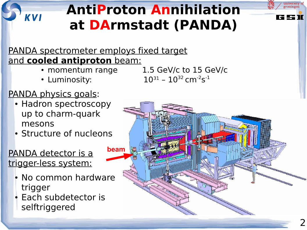
AntiProton Annihilationat DArmstadt (PANDA)
PANDA physics goals:● Hadron spectroscopy
up to charm-quark mesons
● Structure of nucleons
PANDA detector is atrigger-less system:
● No common hardware trigger
● Each subdetector is selftriggered
beam
PANDA spectrometer employs fixed targetand cooled antiproton beam:
● momentum range 1.5 GeV/c to 15 GeV/c● Luminosity: 1031 – 1032 cm-2s-1
3
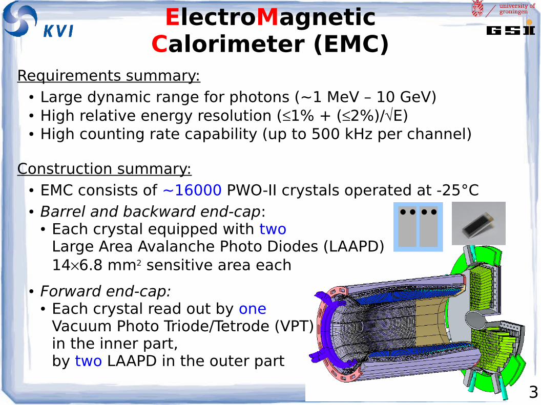
ElectroMagneticCalorimeter (EMC)
Requirements summary:● Large dynamic range for photons (~1 MeV – 10 GeV)● High relative energy resolution (1% + (2%)/E)● High counting rate capability (up to 500 kHz per channel)
Construction summary:● EMC consists of ~16000 PWO-II crystals operated at -25°C● Barrel and backward end-cap:
● Each crystal equipped with two Large Area Avalanche Photo Diodes (LAAPD) 146.8 mm2 sensitive area each
● Forward end-cap:● Each crystal read out by one
Vacuum Photo Triode/Tetrode (VPT)in the inner part,by two LAAPD in the outer part
4
Readout Concept for the EMC
5
Desired Event-Selectionfor the EMC
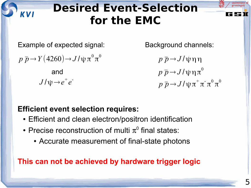
p p̄→Y (4260)→ J /ψπ0π
0 p p̄→ J /ψηη
p p̄→ J /ψηπ0
p p̄→ J /ψπ+π
-π
0π
0
Example of expected signal:
J /ψ→e+e-
and
Background channels:
Efficient event selection requires:● Efficient and clean electron/positron identification● Precise reconstruction of multi 0 final states:
● Accurate measurement of final-state photons
This can not be achieved by hardware trigger logic
6
Requirements forEvent Selection
To achieve the physics goals, the PANDA event selection has to be:
● Efficient:● Detect physics signatures (e.g. secondary vertex, lepton
pair with given invariant mass)● Handle simultaneously several different high-level
event-selection criteria (efficient use of beam time)● Flexible:
● Lets each sub-detector contribute to the high-level selection
● Can be reconfigured without modification of hardware● Is designed modular: same readout for sub-detector
tests and for production experiments● Able to operate at very high rates:
● 20 MHz interaction rate → hit rate ~500 kHz
7
Readout Concept
All requirements can be fulfilled by constructing a Trigger-less Readout with:
● self-triggered intelligent front-end: autonomous hit detection and data pre-processing (e.g. based on Sampling ADC)
● a very precise time distribution system:single clock-source for PANDA (event correlation)
● time-sorting and processing data on-line:processing in FPGA
8
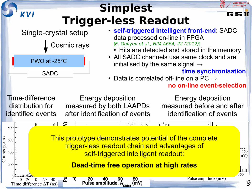
SimplestTrigger-less Readout
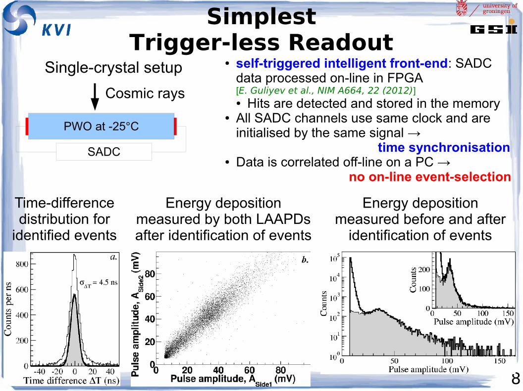
PWO at -25°C
SADC
Cosmic rays
Single-crystal setup
Energy deposition measured by both LAAPDs after identification of events
Time-difference distribution for
identified events
● self-triggered intelligent front-end: SADC data processed on-line in FPGA[E. Guliyev et al., NIM A664, 22 (2012)]● Hits are detected and stored in the memory
● All SADC channels use same clock and are initialised by the same signal → time synchronisation
● Data is correlated off-line on a PC → no on-line event-selection
Energy deposition measured before and after
identification of events
9
SimplestTrigger-less Readout
PWO at -25°C
SADC
Cosmic rays
Single-crystal setup
Energy deposition measured by both LAAPDs after identification of events
Time-difference distribution for
identified events
● self-triggered intelligent front-end: SADC data processed on-line in FPGA[E. Guliyev et al., NIM A664, 22 (2012)]● Hits are detected and stored in the memory
● All SADC channels use same clock and are initialised by the same signal → time synchronisation
● Data is correlated off-line on a PC → no on-line event-selection
Energy deposition measured before and after
identification of events
This prototype demonstrates potential of the completetrigger-less readout chain and advantages of
self-triggered intelligent readout:
Dead-time free operation at high rates
10
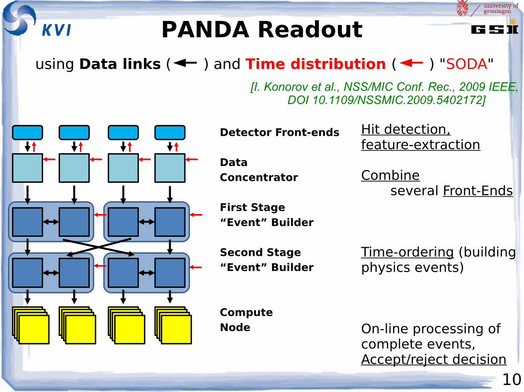
PANDA Readout
Detector Front-ends
Data Concentrator
First Stage“Event” Builder
Second Stage“Event” Builder
ComputeNode
Hit detection,feature-extraction
Combine several Front-Ends
Time-ordering (building physics events)
On-line processing of complete events,Accept/reject decision
[I. Konorov et al., NSS/MIC Conf. Rec., 2009 IEEE, DOI 10.1109/NSSMIC.2009.5402172]
using Data links ( ) and Time distribution ( ) "SODA"

11
Readout forElectromagnetic Calorimeter
Key components of the readout:● Synchronous optical-link connection (clock-signal distribution)● Digitizer module with on-line pulse-processing● Data-concentrator with time-ordered output● High-level on-line data processing
Digitizer
SADC
FPGAOn-line pulse-data
Processing:Feature Extraction
EMC volume DataConcentrator
Hits-data
SADC ClockSync. signalsslow control
Optical link
TimeDistribution
ComputeNode
-25°C
LAAPD
Preamp. Dataconcentration
Event pre-building
12
Synchronous Optical-link Connection
13
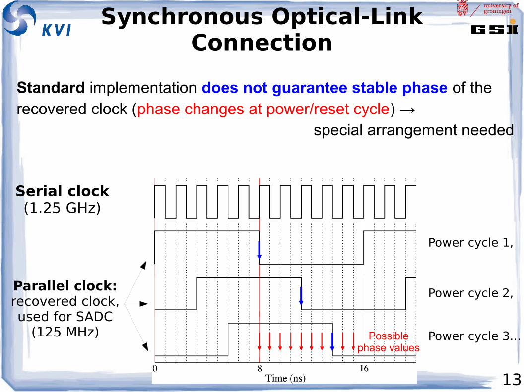
Synchronous Optical-LinkConnection
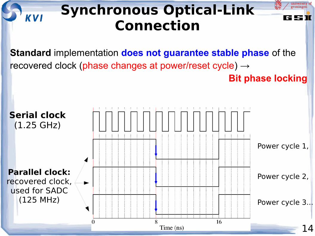
Standard implementation does not guarantee stable phase of the recovered clock (phase changes at power/reset cycle) → special arrangement needed
Serial clock(1.25 GHz)
Parallel clock:recovered clock,used for SADC
(125 MHz)
Power cycle 1,
Power cycle 2,
Power cycle 3...Possiblephase values
14
Synchronous Optical-LinkConnection
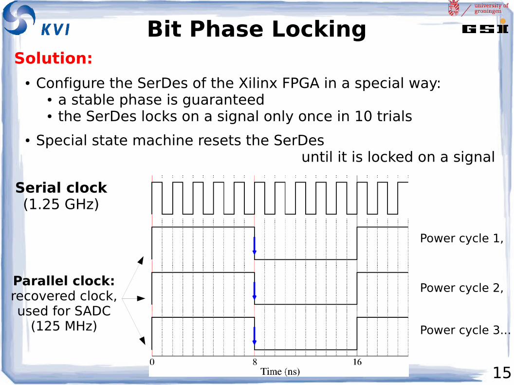
Standard implementation does not guarantee stable phase of the recovered clock (phase changes at power/reset cycle) → Bit phase locking
Serial clock(1.25 GHz)
Parallel clock:recovered clock,used for SADC
(125 MHz)
Power cycle 1,
Power cycle 2,
Power cycle 3...
15
Bit Phase LockingSolution:
● Configure the SerDes of the Xilinx FPGA in a special way:● a stable phase is guaranteed● the SerDes locks on a signal only once in 10 trials
● Special state machine resets the SerDes until it is locked on a signal
Serial clock(1.25 GHz)
Parallel clock:recovered clock,used for SADC
(125 MHz)
Power cycle 1,
Power cycle 2,
Power cycle 3...
16
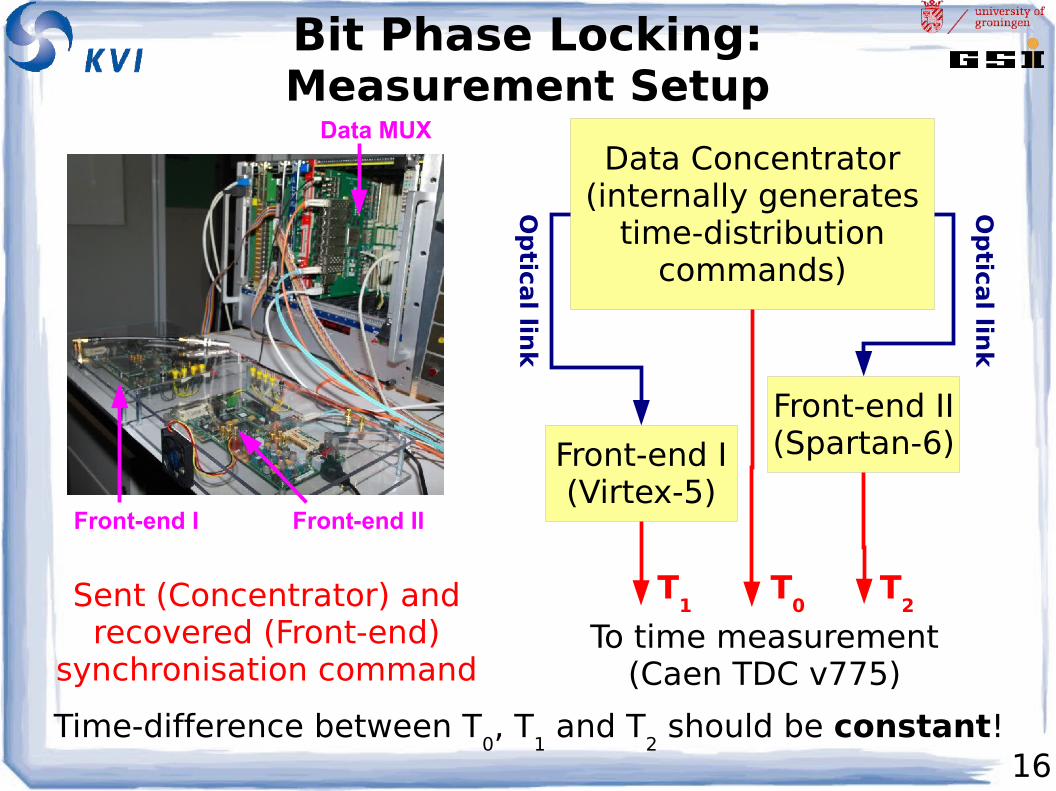
Bit Phase Locking:Measurement Setup
Data Concentrator(internally generates
time-distributioncommands)
Front-end I(Virtex-5)
Front-end II(Spartan-6)
Op
tical lin
k
Op
tical lin
k
To time measurement(Caen TDC v775)
T0
T1
T2Sent (Concentrator) and
recovered (Front-end) synchronisation command
Time-difference between T0, T
1 and T
2 should be constant!
Data MUX
Front-end I Front-end II
17
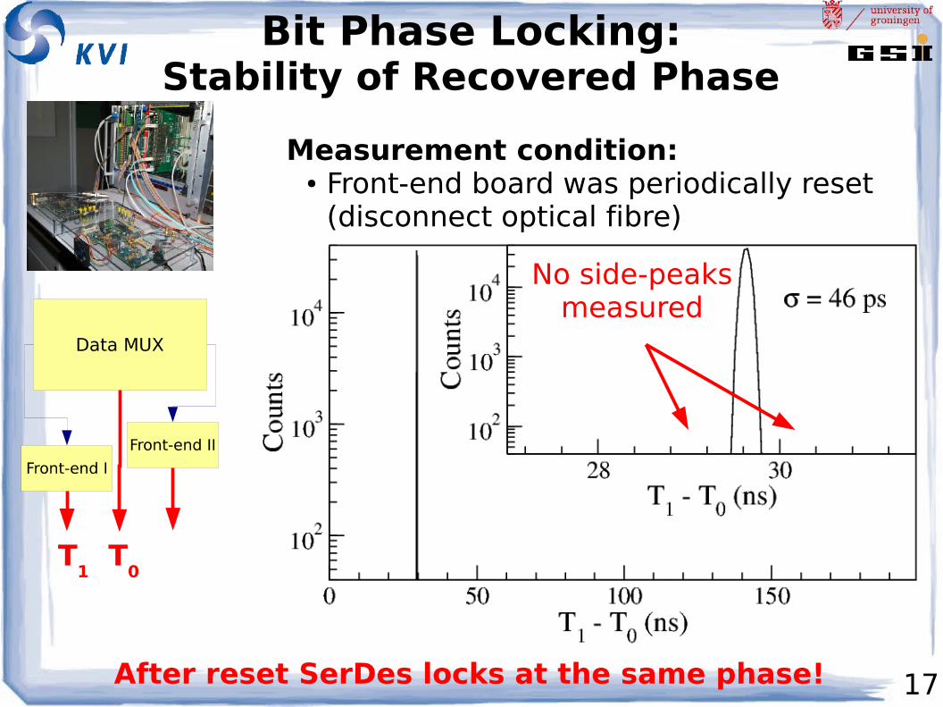
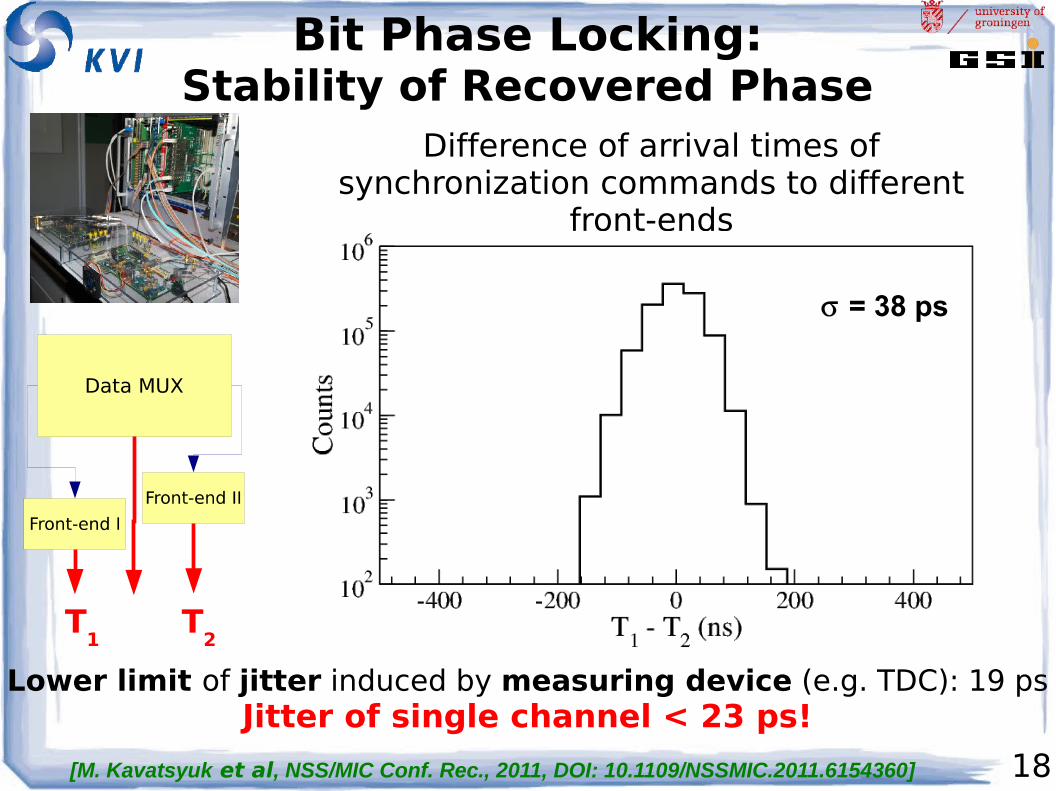
Bit Phase Locking:Stability of Recovered Phase
Measurement condition:● Front-end board was periodically reset
(disconnect optical fibre)
No side-peaksmeasured
After reset SerDes locks at the same phase!
T0
T1
18
Bit Phase Locking:Stability of Recovered Phase
Lower limit of jitter induced by measuring device (e.g. TDC): 19 psJitter of single channel < 23 ps!
Difference of arrival times of synchronization commands to different
front-ends
T2
T1
= 38 ps
[M. Kavatsyuk et al, NSS/MIC Conf. Rec., 2011, DOI: 10.1109/NSSMIC.2011.6154360]
19
Intelligent Front-End:EMC Digitizer
20
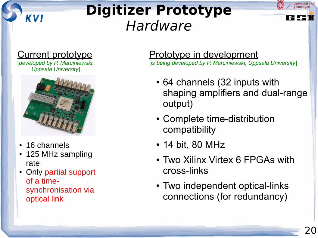
Digitizer PrototypeHardware
● 16 channels● 125 MHz sampling
rate● Only partial support
of a time-synchronisation via optical link
Current prototype[developed by P. Marciniewski,
Uppsala University]
Prototype in development[is being developed by P. Marciniewski, Uppsala University]
● 64 channels (32 inputs with shaping amplifiers and dual-range output)
● Complete time-distribution compatibility
● 14 bit, 80 MHz● Two Xilinx Virtex 6 FPGAs with
cross-links● Two independent optical-links
connections (for redundancy)
21
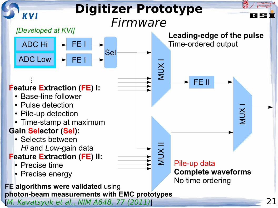
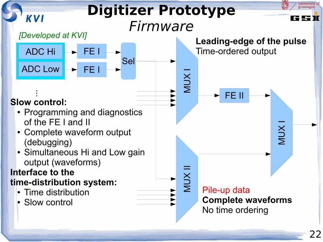
Digitizer PrototypeFirmware
...
ADC Hi
ADC Low
FE I
FE ISel
MU
X I
MU
X II
MU
X I
Leading-edge of the pulseTime-ordered output
FE II
Pile-up dataComplete waveformsNo time ordering
Feature Extraction (FE) I:● Base-line follower● Pulse detection● Pile-up detection● Time-stamp at maximum
Gain Selector (Sel):● Selects between
Hi and Low-gain dataFeature Extraction (FE) II:
● Precise time● Precise energy
FE algorithms were validated usingphoton-beam measurements with EMC prototypes[M. Kavatsyuk et al., NIM A648, 77 (2011)]
[Developed at KVI]
22
Digitizer PrototypeFirmware
...
ADC Hi
ADC Low
FE I
FE ISel
MU
X I
MU
X II
MU
X I
Leading-edge of the pulseTime-ordered output
FE II
Pile-up dataComplete waveformsNo time ordering
Slow control:● Programming and diagnostics
of the FE I and II● Complete waveform output
(debugging)● Simultaneous Hi and Low gain
output (waveforms)Interface to thetime-distribution system:
● Time distribution● Slow control
[Developed at KVI]
23
Data Concentrationand
Processing
24
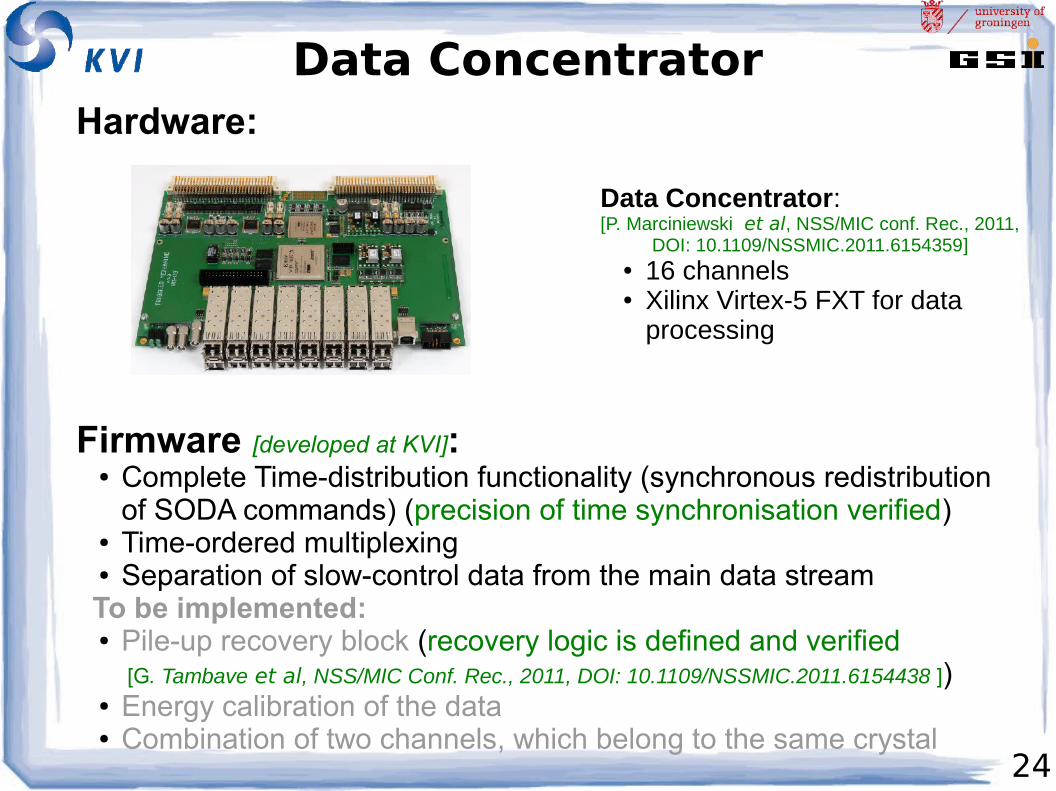
Data Concentrator
Data Concentrator:[P. Marciniewski et al, NSS/MIC conf. Rec., 2011,
DOI: 10.1109/NSSMIC.2011.6154359]● 16 channels● Xilinx Virtex-5 FXT for data
processing
Firmware [developed at KVI]:● Complete Time-distribution functionality (synchronous redistribution
of SODA commands) (precision of time synchronisation verified)● Time-ordered multiplexing● Separation of slow-control data from the main data stream
To be implemented:● Pile-up recovery block (recovery logic is defined and verified
[G. Tambave et al, NSS/MIC Conf. Rec., 2011, DOI: 10.1109/NSSMIC.2011.6154438 ])● Energy calibration of the data● Combination of two channels, which belong to the same crystal
Hardware:
25
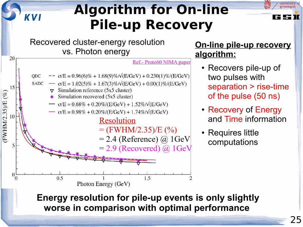
Algorithm for On-linePile-up Recovery
Energy resolution for pile-up events is only slightly worse in comparison with optimal performance
Resolution = (FWHM/2.35)/E (%)= 2.4 (Reference) @ 1GeV= 2.9 (Recovered) @ 1GeV
Ref.- Proto60 NIMA paper
Recovered cluster-energy resolutionvs. Photon energy
On-line pile-up recovery algorithm:
● Recovers pile-up of two pulses with separation > rise-time of the pulse (50 ns)
● Recovery of Energy and Time information
● Requires little computations
26
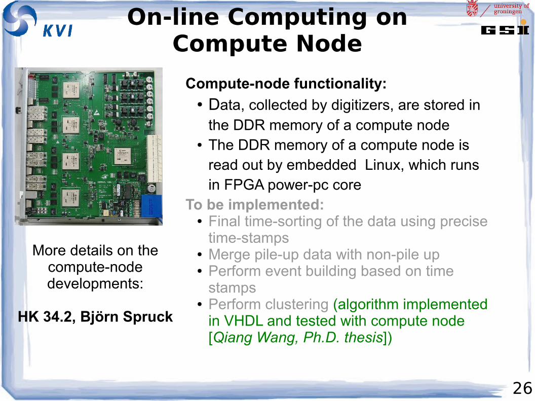
On-line Computing onCompute Node
Compute-node functionality:● Data, collected by digitizers, are stored in
the DDR memory of a compute node● The DDR memory of a compute node is
read out by embedded Linux, which runs in FPGA power-pc core
To be implemented:● Final time-sorting of the data using precise
time-stamps● Merge pile-up data with non-pile up● Perform event building based on time
stamps● Perform clustering (algorithm implemented
in VHDL and tested with compute node [Qiang Wang, Ph.D. thesis])
More details on the compute-node developments:
HK 34.2, Björn Spruck
27
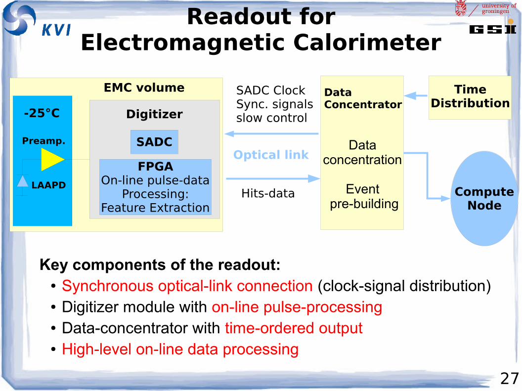
Readout forElectromagnetic Calorimeter
Key components of the readout:● Synchronous optical-link connection (clock-signal distribution)● Digitizer module with on-line pulse-processing● Data-concentrator with time-ordered output● High-level on-line data processing
Digitizer
SADC
FPGAOn-line pulse-data
Processing:Feature Extraction
EMC volume DataConcentrator
Hits-data
SADC ClockSync. signalsslow control
Optical link
TimeDistribution
ComputeNode
-25°C
LAAPD
Preamp. Dataconcentration
Event pre-building
28
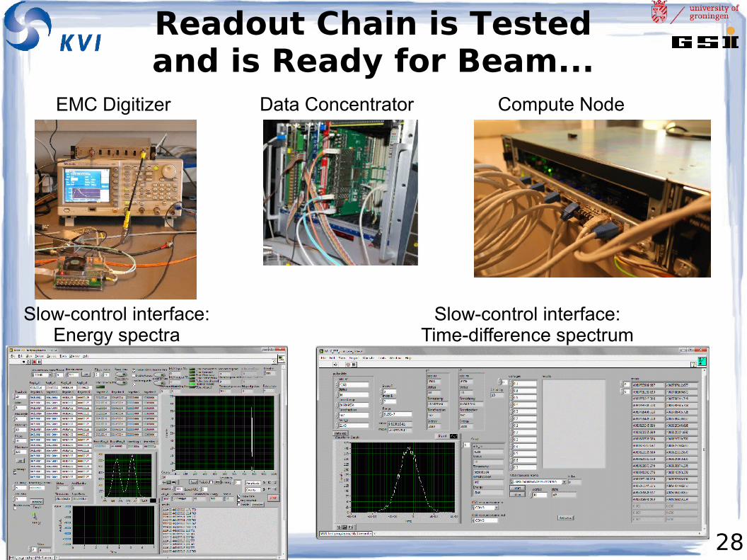
Readout Chain is Testedand is Ready for Beam...
EMC Digitizer Data Concentrator Compute Node
Slow-control interface:Energy spectra
Slow-control interface:Time-difference spectrum
29
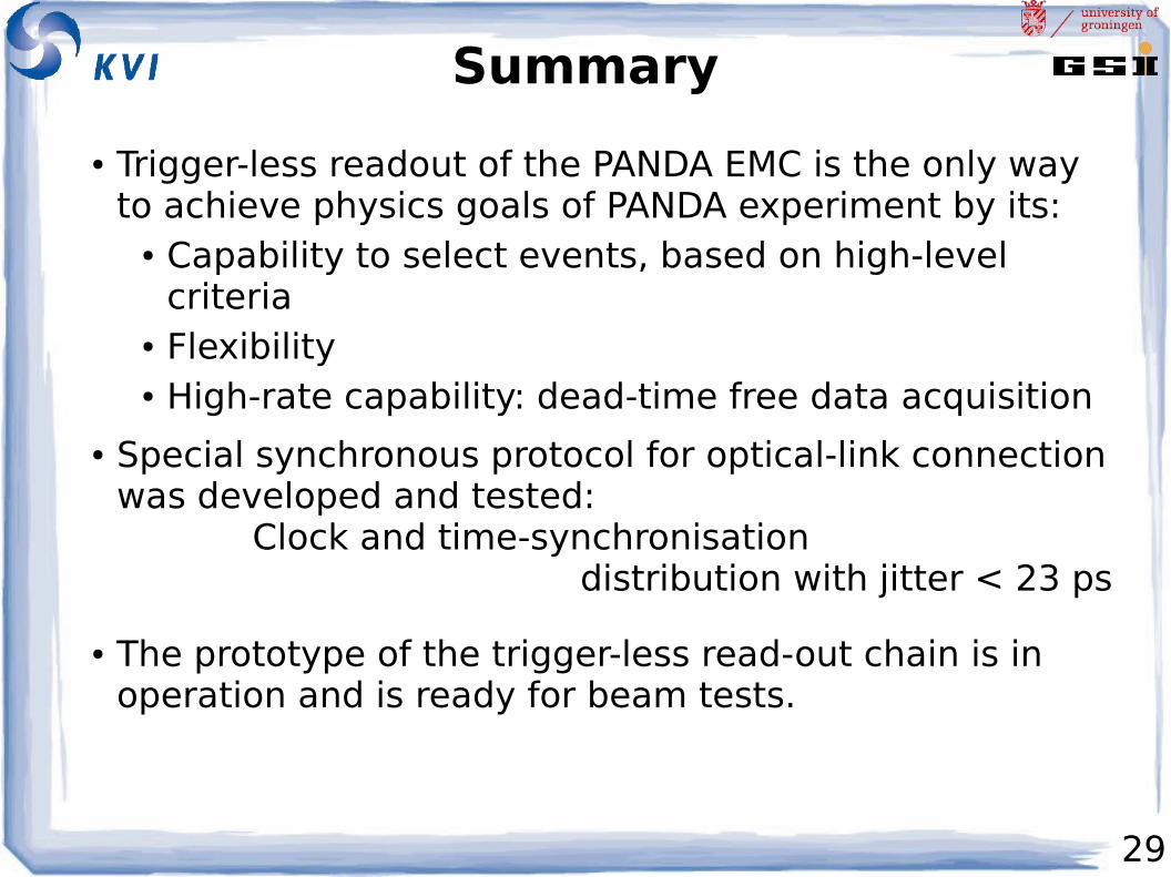
Summary
● Trigger-less readout of the PANDA EMC is the only way to achieve physics goals of PANDA experiment by its:
● Capability to select events, based on high-level criteria
● Flexibility● High-rate capability: dead-time free data acquisition
● Special synchronous protocol for optical-link connection was developed and tested: Clock and time-synchronisation distribution with jitter < 23 ps
● The prototype of the trigger-less read-out chain is in operation and is ready for beam tests.
30
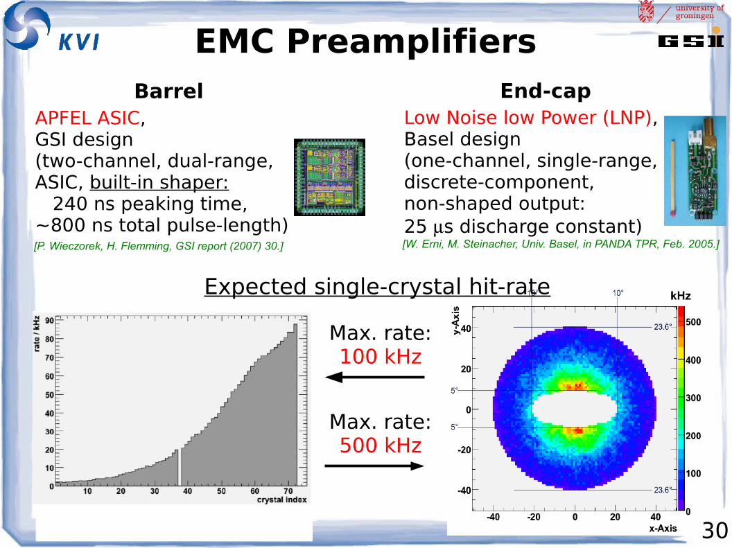
EMC Preamplifiers
Max. rate:100 kHz
End-cap
Max. rate:500 kHz
Barrel
Expected single-crystal hit-rate
Low Noise low Power (LNP), Basel design (one-channel, single-range, discrete-component, non-shaped output: 25 s discharge constant)
APFEL ASIC,GSI design(two-channel, dual-range, ASIC, built-in shaper: 240 ns peaking time, ~800 ns total pulse-length)
[W. Erni, M. Steinacher, Univ. Basel, in PANDA TPR, Feb. 2005.][P. Wieczorek, H. Flemming, GSI report (2007) 30.]
31
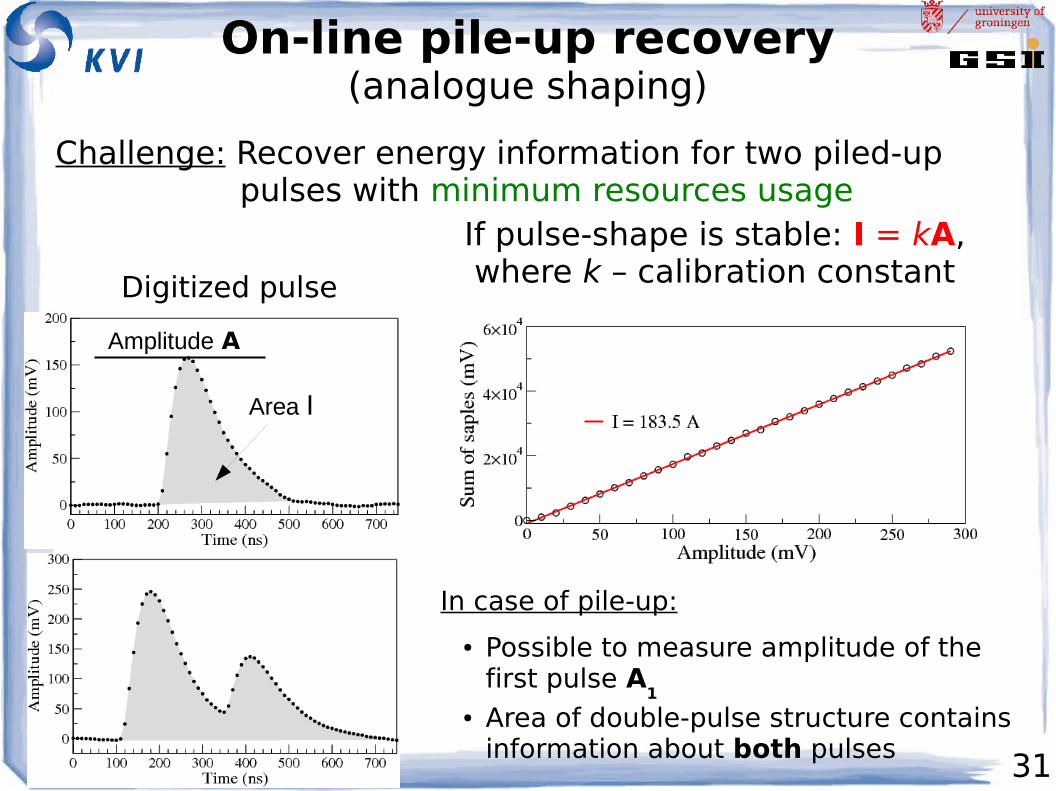
On-line pile-up recovery(analogue shaping)
Challenge: Recover energy information for two piled-up pulses with minimum resources usage
Digitized pulse
Amplitude A
Area I
If pulse-shape is stable: I = kA, where k – calibration constant
In case of pile-up:
● Possible to measure amplitude of the first pulse A
1
● Area of double-pulse structure contains information about both pulses
32
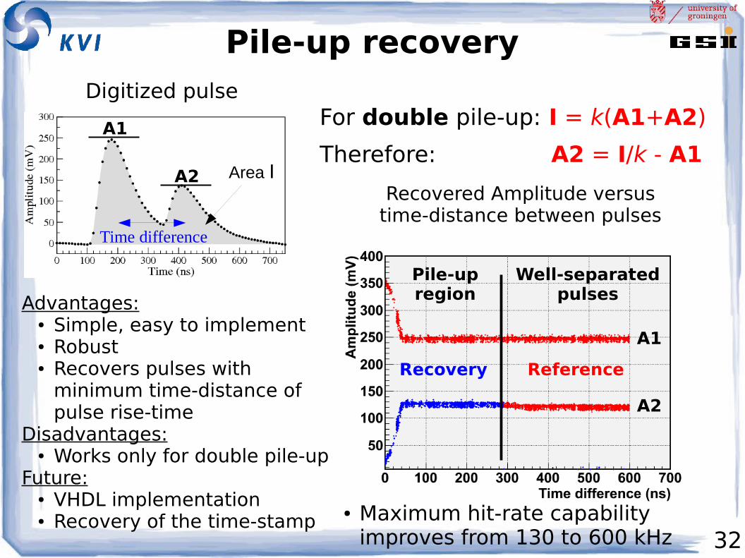
Pile-up recoveryDigitized pulse
Area I
A1
A2
For double pile-up: I = k(A1+A2)
Therefore: A2 = I/k - A1
Time difference
Recovered Amplitude versus time-distance between pulses
A1
A2
Pile-upregion
Well-separatedpulses
ReferenceRecovery
Advantages:● Simple, easy to implement● Robust● Recovers pulses with
minimum time-distance of pulse rise-time
Disadvantages:● Works only for double pile-up
Future:● VHDL implementation● Recovery of the time-stamp
● Maximum hit-rate capability improves from 130 to 600 kHz