Embed Size (px)
Citation preview
22 February 2011
Issue 18 Signal
Tricks of the Trade
Dave Porter G4OYX
In ToTT this time we continue with the description of the MWT BD228A 50 kW MF transmitter installed at BBC Brookman‟s Park, BP, in 1961. Previously, the RF section was detailed and, by the use of a new, patented invention Tyler Mod, incorporating third harmonic resonators in the final stage, the overall efficiency approached 90%. It will be seen later that, because of this development, the modulation power requirements also become
smaller, again a good selling point from MWT to broadcasters.
Starting and finishing points
The basis of the modulator design was a standard push-pull Class B output stage with air-cooled power triodes. As such, the standing feeds with no modulation would be low as the tubes would be biased to near enough cut-off. Accordingly, they would require a fair amount of drive to produce a linear output. Being triodes in Class B rather than tetrodes, beam tetrodes, or pentodes in Class AB1 (or even AB2) implies that considerable grid current will need to flow.
Drive requirements
Of course, a substantial voltage swing is also required on this drive; volts coupled with current equate to power, so a low impedance driver is needed; this was effected by the use of push-pull cathode followers. Quite how this stage was realised in practice is interesting, more about this later.
The voltage swing was relatively easy to source and the then, brand-new M-OV TT21 was used both in quantity and in gay abandon; one even featured as an over-modulation limiter.
This back-to-front route brings us neatly to what MWT called the „‟pre-amplifier‟‟ stage and here, rather than design from scratch, MWT bought in a ready-made hi-fi amplifier with both an input transformer and a modified output transformer.
Conveniently, here at the audio input would be a good point from which to start the detailed explanation.
Input audio and Pre-Amplifier
It was at the time, that the newly introduced Leak TL-12 12 W hi-fi amplifier was employed as a pre-amplifier by MWT. The circuit is shown in figure 1 (page 23). This was a three stage unit employing an EF86 as voltage amplifier with an ECC81 phase splitter to two push-pull EL84s in ultra-linear configuration in the output. The programme material arrived by 600 Ohm balanced feed via the transmitter‟s own input transformer, TR12 at up to +8dBm into transformer TR3 where it was suitably attenuated by R23, R24, and „‟tone corrected‟‟ by R25, C16m and C17. More tone correction
was employed by a modification for half power, 25 kW
operation comprising two 0.1 F capacitors and a 200 Ohm resistor.
The TL-12 output transformer was to a different design from that supplied to regular hi-fi users in that instead of the output being for a 4 or 15 Ohm speaker, two phased outputs were present with the required load being 100 Ohms for each. These two windings also allowed for the application of overall modulator negative feedback.
A tertiary winding was provided at low impedance in lieu of the 4 or 15 Ohm feed as a source of the 26 dB negative feedback for the Leak TL-12 itself.
On the photograph of the modulator general layout (figure 2) the position of the preamp is hard to discern, however, it was mounted within the modulator cabinet high up above the RH front door.
Figure 2. The modulator cubicle

Signal Issue 18
February 2011 23
Fig
ure
1. C
irc
uit
dia
gra
m o
f th
e p
re-a
mp
lifi
er,
ac
tua
lly a
mo
dif
ied
Le
ak
TL
-12
, 1
2 W
att
am
plifi
er.

24 February 2011
Issue 18 Signal
It’s hot in here!
The TL-12 chassis was mounted vertically so the valves were horizontal. For two reasons this proved to be a problem. First, the cabinets would be hot in the summer,
often running at 105F – 115F and, with the amplifier high up, its operating temperature was no doubt more than that for which Mr Leak designed. This led to component failure and the cathode bias resistors on the EL84s were up-rated from 1 W carbon composition types to 2 W. Secondly, these resistors were also in danger from thermal runaway caused by the placing of the tubes horizontally. The control grid structure of the EL84 was prone to displacement by horizontal sagging and the tubes would go grid/cathode leaky with consequent sky-high anode current.
Figure 3. Detail of front left hand side of the modulator cubicle with one of the output valves
(front left),
Examination of Figure 1 will reveal a local BP modification where, in the 0 V return of the centre-tap of
the main HT transformer, a meter shunt has been wired. Connections to the outside world were via an unused American 110 V/220 V facilities socket (SKC). A spare, switched way on SWE was found to one of the Ernest Turner front panel meters and a regular check could be made of Leak TL-12 total HT current.
One other „nasty‟ of this pre-amplifier was supersonic oscillation which has been alluded to in a previous ToTT. Here certain specimens of EF86 can cause, after time, the amplifier to „take-off‟ at about 80 kHz causing spurious output. This was not good for the resistive parasitic stoppers on the inputs to the modulation transformer; on a 250 kW BD272 HF sender these could glow red-hot when the Leak TL-12 fault was present! In addition the attentions of the Government‟s RF spectrum monitoring stations are raised, again not good…..
Baldock is not far from BP!
At Brookman‟s Park, after these „undocumented features‟ had been discovered, it was arranged that every year around Christmas, the Leak Amp would have a complete new set of glassware whether it needed it or not. This was a sensible approach; it wasn‟t the same on the HF stations with their BD272 Leak pre-amps! They were run to destruction and normally staff would dash in, prior to or even during a transmission and change the amplifier for one that did not distort or sprog!
The Modulator output triodes V16 and V17, type STC 3J/252EW, can be seen within their air cell cavities, one on each side of the modulator cubicle shown in figure 2, and with V16 in more detail in figure 3. Other principal features of this general view (figure 2) are the Willmott Breedon key interlock system with SWC and SWD adjacent to each other (top left of cubicle), and with SWA (central panel) as the main control sequence switch which enabled progressive manual control of air, filaments, bias, aux HT, and HT, etc., or in „Remote‟ whereby the closure of a remote toggle switch was used to power up or power down the transmitter.
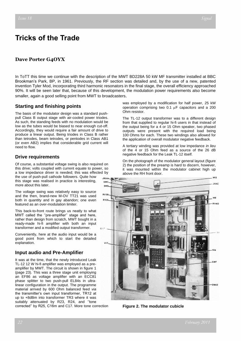
The first AF amplifier
Referring to the circuit diagram in Figure 4 (page 25) the first AF amplifier uses a push-pull pair of TT21s. They have a common cathode circuit with a front panel mounted bias adjusting resistor RV23.
Dynamic balance of the stage gain is via RV21, labelled “1
st AF Balance”, in the anode circuit of
V1; essentially the anode load and hence stage gain of one tube is adjustable. Each TT21 grid is supplied by audio and bias voltage through the secondaries of the Leak pre-amp output
transformer. Points x-x‟ and y-y‟ are the injection nodes for the transmitter‟s overall negative feedback.
As usual, and as on the RF section, comprehensive metering was provided both switched and permanent. Anode and screen supplies came from a nominal 250 V supply.
Signal Issue 18
February 2011 25
Figure 4. Circuit diagram of the first AF amplifier
26 February 2011
Issue 18 Signal
Voltage Amplifier
The outputs from the 1st AF are resistance-capacity
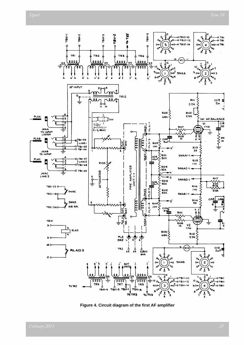
coupled to the next stage, the Voltage Amplifier, whose circuit diagram is shown in figure 5 (page 27). Four TT21s are used in parallel push-pull. Each valve is part auto- and part fixed-biased, and each valve‟s bias is adjusted by separate potentiometers on the TX front panel. A 1 kV anode supply, and resistance dropped screen supply derived from the 2kV supply is used on this stage.
Mechanically both this stage and the preceding one are let‟s say, odd, in that the tubes are mounted upside-down on a chassis runner, evident from inspection of the units in the right hand compartment of the modulator cubicle (figure 2) and from the detail of figure 6 (below). Maybe it was to make construction and possible later fault-finding easier in that all the connections were on the top in the clear. However this mode required the use of glass fibre reinforced retaining harnesses to prevent the valves from falling out!
As a ruse to sell more valves, it was probably a good idea as all the heat went away through the base of the valve and the valveholder, which possibly shortened both their lives.
Figure 6. Detail of the ‘upside down’ amplifier chassis
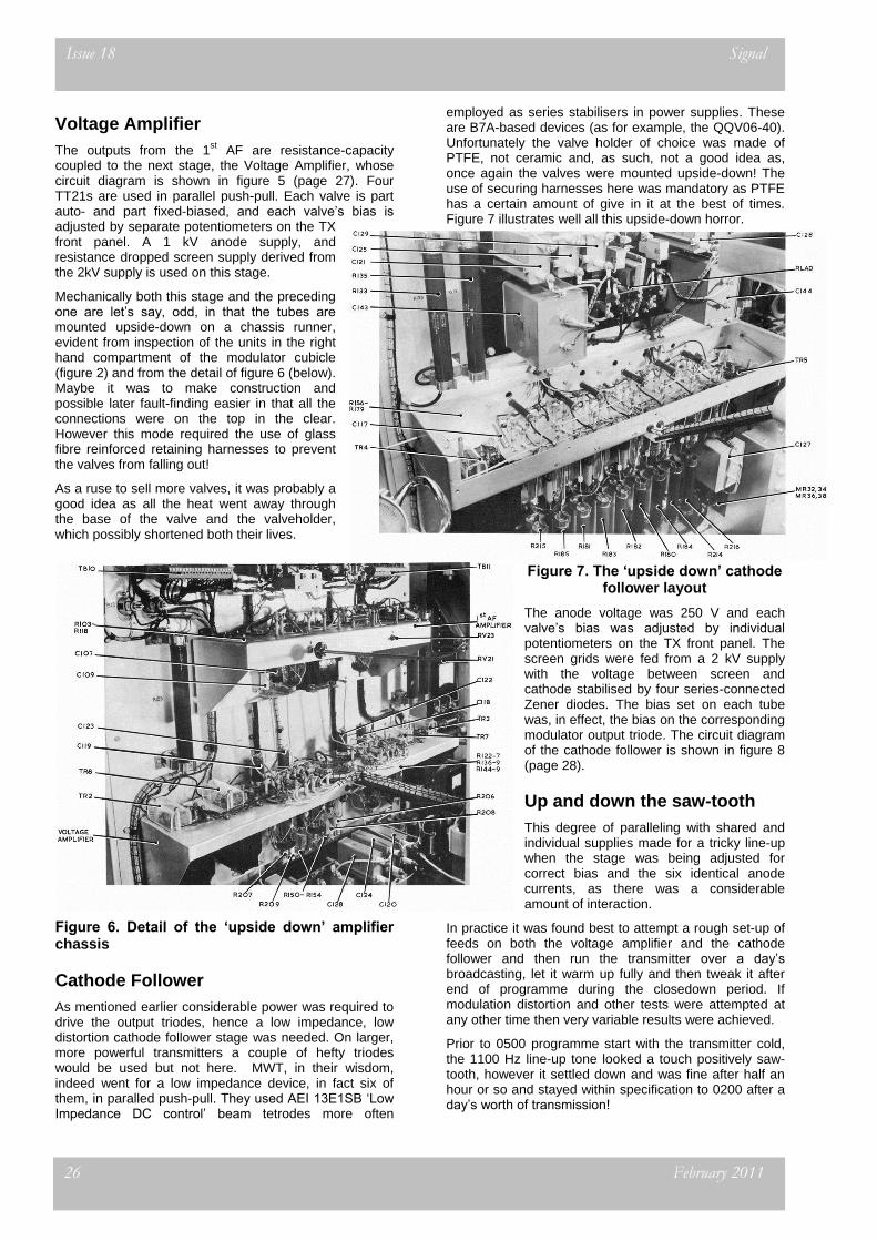
Cathode Follower
As mentioned earlier considerable power was required to drive the output triodes, hence a low impedance, low distortion cathode follower stage was needed. On larger, more powerful transmitters a couple of hefty triodes would be used but not here. MWT, in their wisdom, indeed went for a low impedance device, in fact six of them, in paralled push-pull. They used AEI 13E1SB „Low Impedance DC control‟ beam tetrodes more often
employed as series stabilisers in power supplies. These are B7A-based devices (as for example, the QQV06-40). Unfortunately the valve holder of choice was made of PTFE, not ceramic and, as such, not a good idea as, once again the valves were mounted upside-down! The use of securing harnesses here was mandatory as PTFE has a certain amount of give in it at the best of times. Figure 7 illustrates well all this upside-down horror.
Figure 7. The ‘upside down’ cathode follower layout
The anode voltage was 250 V and each valve‟s bias was adjusted by individual potentiometers on the TX front panel. The screen grids were fed from a 2 kV supply with the voltage between screen and cathode stabilised by four series-connected Zener diodes. The bias set on each tube was, in effect, the bias on the corresponding modulator output triode. The circuit diagram of the cathode follower is shown in figure 8 (page 28).
Up and down the saw-tooth
This degree of paralleling with shared and individual supplies made for a tricky line-up when the stage was being adjusted for correct bias and the six identical anode currents, as there was a considerable amount of interaction.
In practice it was found best to attempt a rough set-up of feeds on both the voltage amplifier and the cathode follower and then run the transmitter over a day‟s broadcasting, let it warm up fully and then tweak it after end of programme during the closedown period. If modulation distortion and other tests were attempted at any other time then very variable results were achieved.
Prior to 0500 programme start with the transmitter cold, the 1100 Hz line-up tone looked a touch positively saw-tooth, however it settled down and was fine after half an hour or so and stayed within specification to 0200 after a day‟s worth of transmission!
Signal Issue 18
February 2011 27
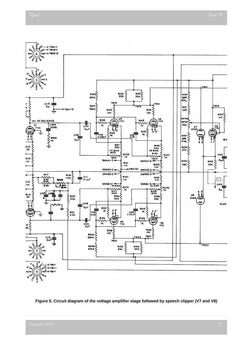
Figure 5. Circuit diagram of the voltage amplifier stage followed by speech clipper (V7 and V8)

28 February 2011
Issue 18 Signal
Figure 8. Circuit diagram, of the cathode follower stage
Signal Issue 18
February 2011 29
Limiter, well clipper really!
As has been mentioned before in ToTT it‟s prudent not to over-modulate and MWT provided a rudimentary limiter/clipper in the BD228A (figure 5). This gave last-chance protection in case the BBC Limiters let through a spike.
EY84 diodes (V7 and V8) were connected across each side of the push-pull system with the cathodes commoned and connected to the cathode of a TT21 (V9), the grid voltage of which was controlled by a front panel mounted potentiometer (RV28). The level at which the limiting/clipping starts is controlled by this potentiometer.
Main modulator
With the RF PA efficiency approaching 90%, to achieve 50 kW output then about 55 kW modulated input DC is required. Assuming that there is minimal loss in the modulation transformer, this modulator needs to deliver about half this amount, so nominally 30 kW AF.
Had this transmitter not incorporated Tyler Mod on the RF section, then the PA efficiency would have been typically 70% so about 70 kW of DC input would be needed, and a corresponding 35 – 40 kW of audio power.
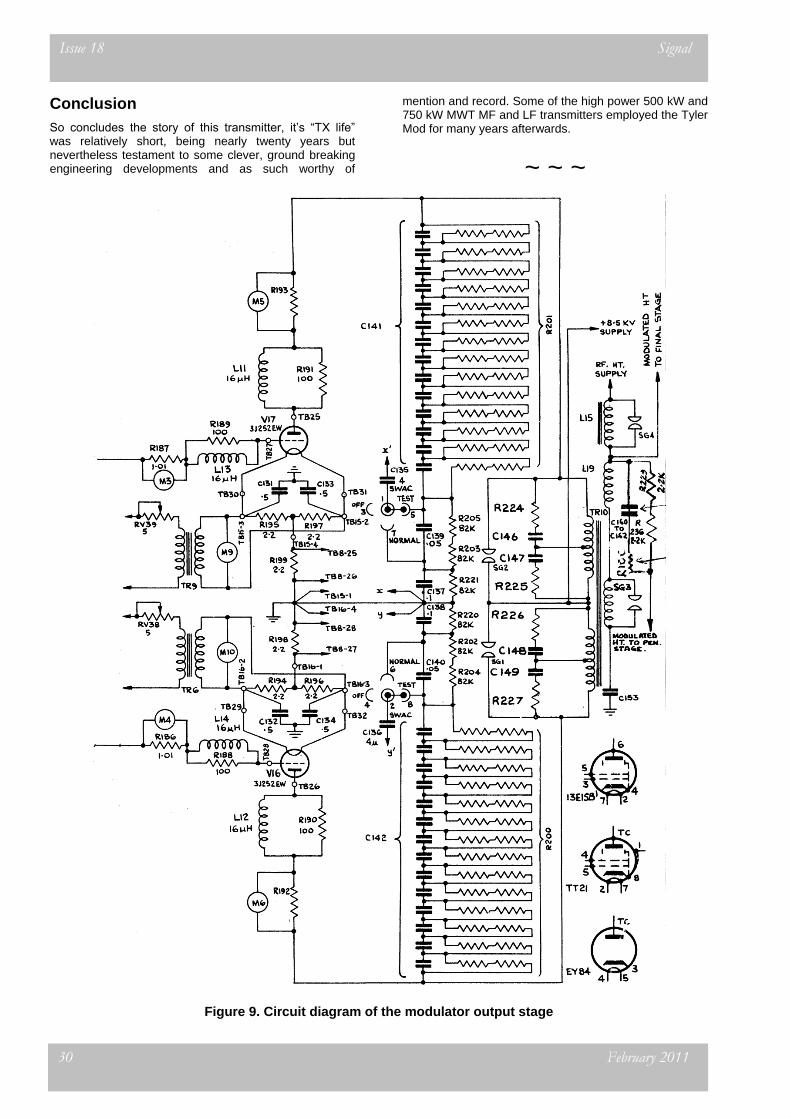
The circuit diagram of the output stage is shown in figure 9 (page 30). The STC 3J/252EW output valve filaments were heated at 8 V AC. Bias was obtained via the dc connected cathode follower stage. The main HT of 8.5 kV was from a mercury arc rectifier and was common to the RF PA, etc.
Shunt modulation was used and was exactly as described in previous issues of Signal, there being a modulation transformer, modulation reactor and blocking capacitors.
Figure 10. Feedback ladder
Negative feedback was obtained by a pair of „Feedback Potentiometers‟ (always known as „feedback ladders‟ in the trade) one for each output valve. Figure 10 shows one of the strings of fourteen 0.004uF block mica capacitors comprising an overall C142. Each capacitor was bypassed by a series pair of 1 M Ohm 2 W Body-Tip-Spot carbon rod resistors, the series comprising R200. At the earth end of this string was a series pair of
82 k resistors, again bypassed by a capacitor. Selection, by U Link to points „x‟ and „y‟ mentioned earlier (figure 4), of a certain portion of the voltage across the ladder gave the normal 15 dB of negative feedback. However, for test, „zero‟ feedback could be selected, or „full‟ feedback which is at 21dB.
As befits this transmitter, if previous experience of anti-parasitic devices is cited, is the use of various control grid, screen grid, and anode anti-squegger components on all stages of the modulator.
Monitoring, operation and problems
Unlike later transmitters, no internal AF monitoring was provided in the form of a transmitter-mounted demodulator. The later 1977, 50 kW B6034 Doherty sported a very well-engineered demodulator unit and even the 1963 250 kW BD272 had a crystal set, using an EY84 as a detector for audio monitoring. In the event at BP, a BBC-designed Modulation Monitoring Unit (to be described in a future ToTT) was employed, fed from an output feeder probe.
The operation of the BD228A (called T6 at BP) was relatively easy in that its circuitry was straightforward and that, of course, wavechanges were not needed. The usual requirements of air filter cleaning and transmitter dust removal, coupled with regular inspections of valve currents and general meter checks, made for reliable operation. Replacement of one or more of the six AR63 mercury arc rectifiers used for the 8.5 kV HV supply was fairly routine after a series of arc-backs and consequent trips. The rest of the HT rectifier comprised two BT89/CV2109, B4-based thyratrons permitting very rapid suppression and control of repowering.
In some 40 years experience with these rectifiers (of T6 and the MWT BD272 250 kW sender) the author cannot
recall ever changing a BT89 in anger. Indeed when the larger 12 x AR64 600 kW MAR were replaced in 1982 on the BD272, the BT89 were kept to drive the suppression devices fitted. Some of the BD272 BT89s have in excess of 215,000 hours of operation on them, a truly remarkable device.
Mention was made earlier of the dynamic balance potentiometer in the 1
st AF stage. During tests in
1961, „frying noises‟ were heard on plain carrier. The fault took a lot of finding and the culprit was the Colvern potentiometer RV21 2.5 k that was wired as a rheostat in the anode feed to one of the TT21s. A component of larger dissipation cured the fault.
In the 250 kW sender of 1963, the same dynamic balance requirement was required but in the event (maybe because of the problem reported at BP) it was executed differently and a sizeable pot was
again used. The HT was to the slider and each end went to the two TT21 anodes in series with a fixed component, of course, to enable a balance in gain to be obtained. This arrangement was effective and trouble-free.
From 1961 onwards, T6 first carried the Light Programme on 1214 kHz, then Radio One after September 1967 and, after 23 November 1978, Radio Three on 1215 kHz until that service was transferred to a B6034 50 kW Doherty in 1980. T6 was then scrapped.
30 February 2011
Issue 18 Signal
Conclusion
So concludes the story of this transmitter, it‟s “TX life” was relatively short, being nearly twenty years but nevertheless testament to some clever, ground breaking engineering developments and as such worthy of
mention and record. Some of the high power 500 kW and 750 kW MWT MF and LF transmitters employed the Tyler Mod for many years afterwards.
~ ~ ~
Figure 9. Circuit diagram of the modulator output stage