Embed Size (px)
Citation preview
TRIAL USE OF SOLAR POWER AUTOMATIC IRRIGATION SYSTEM
GEO REPORT No. 194
B.L.S. Lui
GEOTECHNICAL ENGINEERING OFFICE
CIVIL ENGINEERING AND DEVELOPMENT DEPARTMENT
THE GOVERNMENT OF THE HONG KONG
SPECIAL ADMINISTRATIVE REGION
TRIAL USE OF SOLAR POWER AUTOMATIC IRRIGATION SYSTEM
GEO REPORT No. 194
B.L.S. Lui
This report was originally produced in January 2005 as GEO Technical Note No. TN 2/2005
- 2 -
© The Government of the Hong Kong Special Administrative Region First published, November 2006 Prepared by: Geotechnical Engineering Office, Civil Engineering and Development Department, Civil Engineering and Development Building, 101 Princess Margaret Road, Homantin, Kowloon, Hong Kong.

- 3 -
PREFACE
In keeping with our policy of releasing information which may be of general interest to the geotechnical profession and the public, we make available selected internal reports in a series of publications termed the GEO Report series. The GEO Reports can be downloaded from the website of the Civil Engineering and Development Department (http://www.cedd.gov.hk) on the Internet. Printed copies are also available for some GEO Reports. For printed copies, a charge is made to cover the cost of printing. The Geotechnical Engineering Office also produces documents specifically for publication. These include guidance documents and results of comprehensive reviews. These publications and the printed GEO Reports may be obtained from the Government’s Information Services Department. Information on how to purchase these documents is given on the second last page of this report. R.K.S. Chan
Head, Geotechnical Engineering Office November 2006
- 4 -
FOREWORD
To assist the establishment of newly planted vegetation on man-made slopes and keep vegetated man-made slopes green during dry seasons, an automatic irrigation system using solar power for watering vegetation may be used. A field trial of the irrigation system has been carried out on slope no. 10SW-D/F75 at Kau Shat Wan in Lantau Island.
The study was carried out by Ms B L S Lui under the
supervision of Mr Y K Shiu. Ms Rebecca Y H Chau and Mr Freeman T S Hui provided advice on vegetation growth. Mr Hugh H H Choy provided assistance in facilitating the site trial and the subsequent monitoring of the system performance. CGE/GP and CGE/LPM2 provided constructive comments on a draft of this report. All their contributions are gratefully acknowledged.
W K Pun Chief Geotechnical Engineer/Standards & Testing
- 5 -
ABSTRACT
A solar power automatic irrigation system was tried out on a vegetated slope at Kau Shat Wan in Lantau Island. The Electrical and Mechanical Services Department was engaged to run a contract for the design, supply and installation of the system.
In the trial, photovoltaic panels are used to generate electricity which is stored in rechargeable batteries. The batteries provide power for the operation of the system. A submersible pump pumps water from a natural stream course to a storage tank and the water is then drawn by an irrigation pump to the sprinklers installed at the slope toe for watering the vegetation on the slope. The system was installed in July 2003 and had been on trial for a year. The system had several failures in the initial trial period. It has been performing satisfactorily since modifications were made to the system in May 2004.
Results of the trial have demonstrated the feasibility of the solar power irrigation system. If irrigation is considered necessary for a slope, the use of an automatic irrigation system operated by solar power could be an option. Guidance on the design of the system is provided.
- 6 -
CONTENTS
Page No.
Title Page 1 PREFACE 3 FOREWORD 4 ABSTRACT 5 CONTENTS 6 1. INTRODUCTION 7 2. SITE DESCRIPTION 7 3. IRRIGATION REQUIREMENT AND WATER SOURCE 7 4. THE SOLAR POWER AUTOMATIC IRRIGATION SYSTEM 8
4.1 General 8
4.2 Solar Power Sub-system 8
4.3 Electrical Control Sub-system 8
4.4 Pumping and Irrigation Sub-system 9 5. MAINTENANCE OF THE SYSTEM 9
5.1 Maintenance during Defects Liability Period 9
5.2 Maintenance after Defects Liability Period 10 6. PERFORMANCE OF THE SYSTEM 10 7. CONCLUSION 11 8. REFERENCES 11 LIST OF TABLES 12 LIST OF FIGURES 14 LIST OF PLATES 20 APPENDIX A: GUIDELINES FOR DESIGN OF A SOLAR POWER 27 AUTOMATIC IRRIGATION SYSTEM
- 7 -
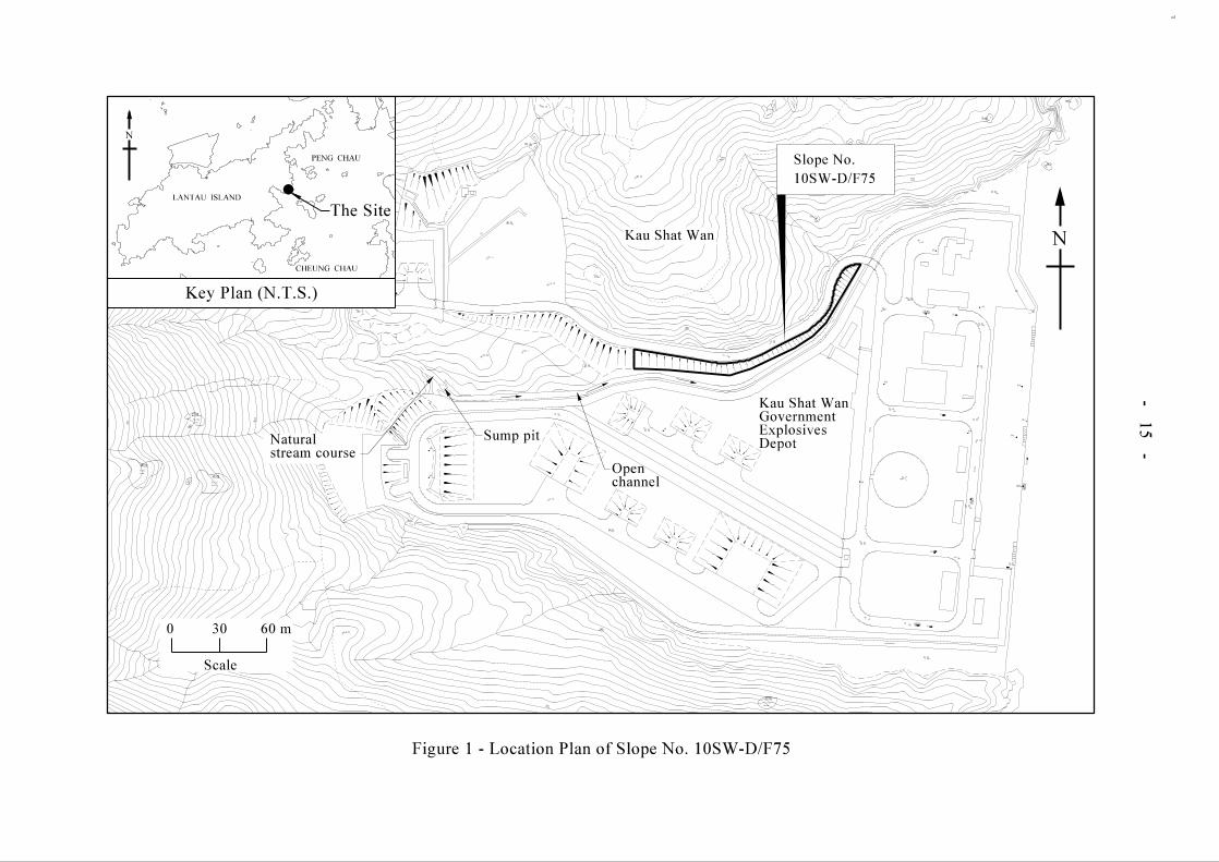
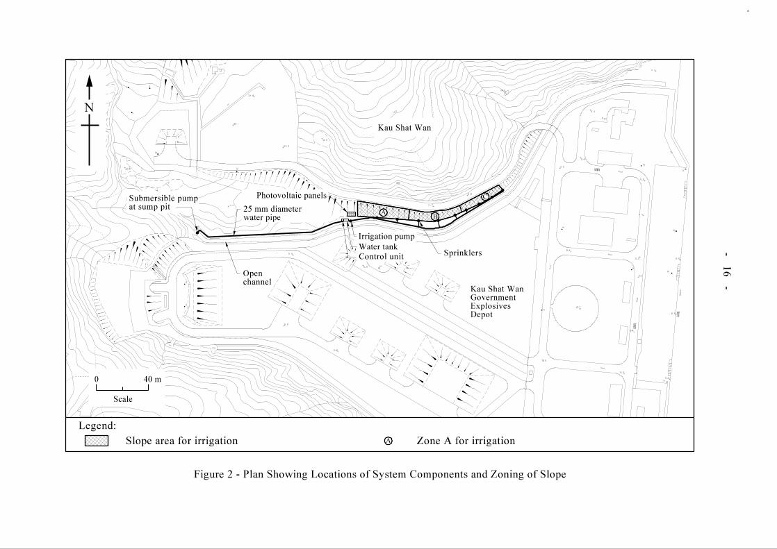
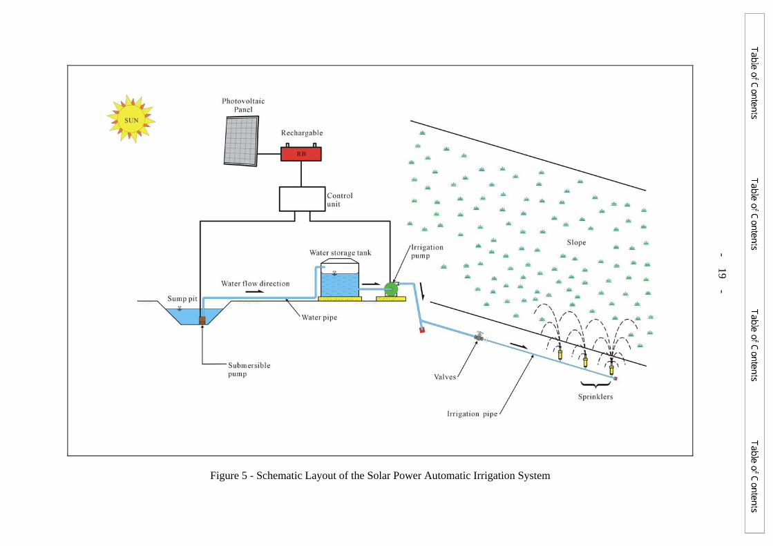
1. INTRODUCTION Irrigation is necessary in the establishment of newly planted vegetation on man-made slopes and for keeping vegetated man-made slopes green during dry seasons. A trial use of a solar power irrigation system for watering vegetation has been carried out. The objective of the trial is to explore the feasibility of using solar energy for extracting water from underground or from stream course for irrigating vegetation on man-made slopes. The trial has been conducted on a slope no. 10SW-D/F75 at the Kau Shat Wan Explosives Depot in Lantau Island. This report documents the design, installation and performance of the solar power automatic irrigation system of the trial. It also provides guidance on the applications and design of a solar power irrigation system. A feasibility study on the use of solar power irrigation system was carried out before. The results of the study together with proposed components of an irrigation system are reported in Leung (2002). 2. SITE DESCRIPTION Slope No. 10SW-D/F75 was selected for trying out the solar power automatic irrigation system. The location of the slope is shown in Figure 1. It is a reinforced fill slope formed as part of the construction of the Kau Shat Wan Explosives Depot in 1997. It stands at about 45° to the horizontal and has a maximum slope height of about 7.5 m. The slope is about 120 m long. The vegetation on the slope mainly consists of grass and a few trees. Plate 1 shows a general view of the slope. A large open channel runs along the toe of the slope. The channel conveys water from a natural stream course into the sea. There is a sump pit at the junction of the channel and the stream course. The sump pit is about 2 m deep. The locations of the channel, the stream course and the sump pit are shown in Figure 1. There is persistent water flow in the stream course and the channel all year round. 3. IRRIGATION REQUIREMENT AND WATER SOURCE The slope area to be irrigated is approximately 1,200 m2. The design watering need of the slope vegetation was assumed to be 10 litres/m2 every week. The irrigation area was divided into three zones (A, B and C). To keep the amount of water and power required to a low level, the three zones were watered in turn, with one zone per day (i.e. irrigating each zone twice a week in a 3-day cycle). Figure 2 shows the zoning of the slope. With a watering requirement of 10 litres/m2 per week, the quantity of water required per day is estimated to be 2,000 litres per irrigation per zone. Water from the stream course is used for the irrigation system.
- 8 -
4. THE SOLAR POWER AUTOMATIC IRRIGATION SYSTEM
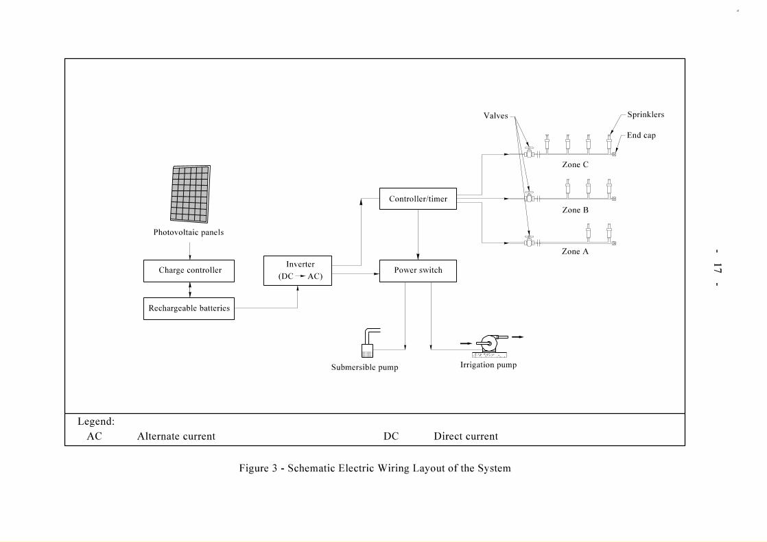
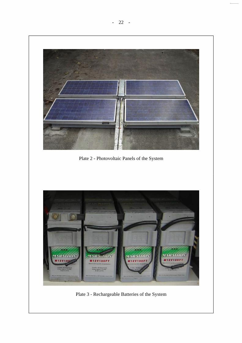
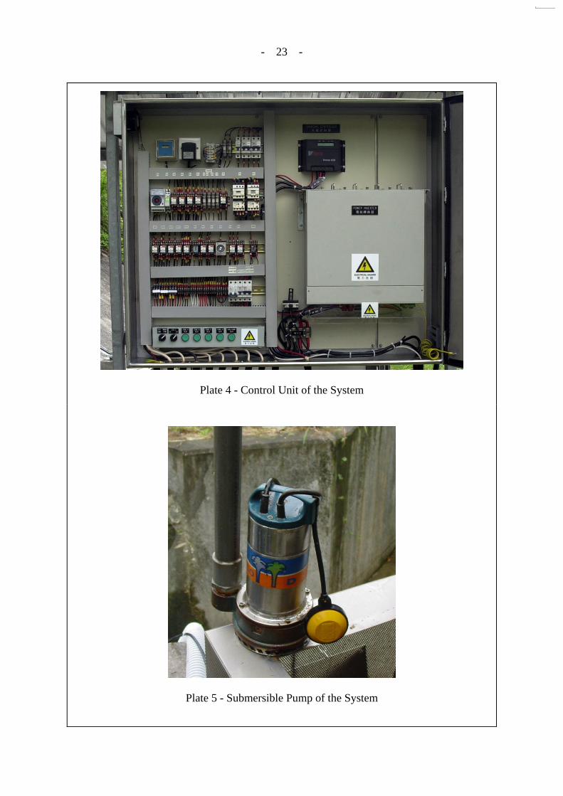
4.1 General The Electrical and Mechanical Services Department (EMSD) has been engaged to manage a contract for the design, supply and installation of the system. The Contractor is Schmidt Biomedtech (H.K.) Ltd. The contract commenced on 3.3.2003 and the system installation was completed on 28.7.2003. The one-year defects liability period started right after the system completion and ended on 28.7.2004. The sum of the system installation contract is $399,590.00. Table 1 shows the breakdown of cost of the system equipment. In this trial, the solar power automatic irrigation system comprises three major sub-systems: (i) solar power sub-system, (ii) electrical control sub-system and (iii) pumping and irrigation sub-system. 4.2 Solar Power Sub-system The solar power sub-system comprises photovoltaic (PV) panels and rechargeable batteries. The PV panels generate electricity, which is then transferred to and stored in the rechargeable batteries. The batteries provide power for the operation of the other equipment. Four numbers of PV panels are used in the system, each measuring 1.575 m x 0.826 m and weighing 17 kg. The power output of each panel is 150 W and the efficiency is about 11%. The panels are mounted on a shotcreted slope adjoining the slope to be irrigated. Plate 2 shows the PV panels used in the system. In order to get maximum sunlight intensity, the PV panels are oriented in a southerly direction at an exposed area. Eight rechargeable batteries, each having a capacity of 100 Ah, are used in the system. The rechargeable batteries are able to provide back up energy for the system to ensure normal operation of three consecutive days even in overcast weather. The required capacity of the rechargeable batteries is determined on the basis of the daily power consumption and the minimum number of days for which the system can still be in effective operation under overcast weather. Plate 3 shows the rechargeable batteries. 4.3 Electrical Control Sub-system All the equipment of the solar power automatic irrigation system is controlled by a control unit which contains electrical timers, control relays, a charge controller and an inverter. Plate 4 shows the control unit. The timers and control relays control the period for the operation of the pumping and irrigation system. The charge controller controls the charging of the batteries by the PV panels. The inverter converts the direct current from the rechargeable batteries into alternate current for the operation of pumps. A rain detector is connected to the control unit of the system for detecting rainfall. If rain is detected within three hours before a scheduled irrigation, the irrigation function of the system will be skipped on that day.
- 9 -
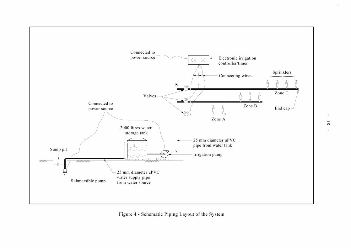
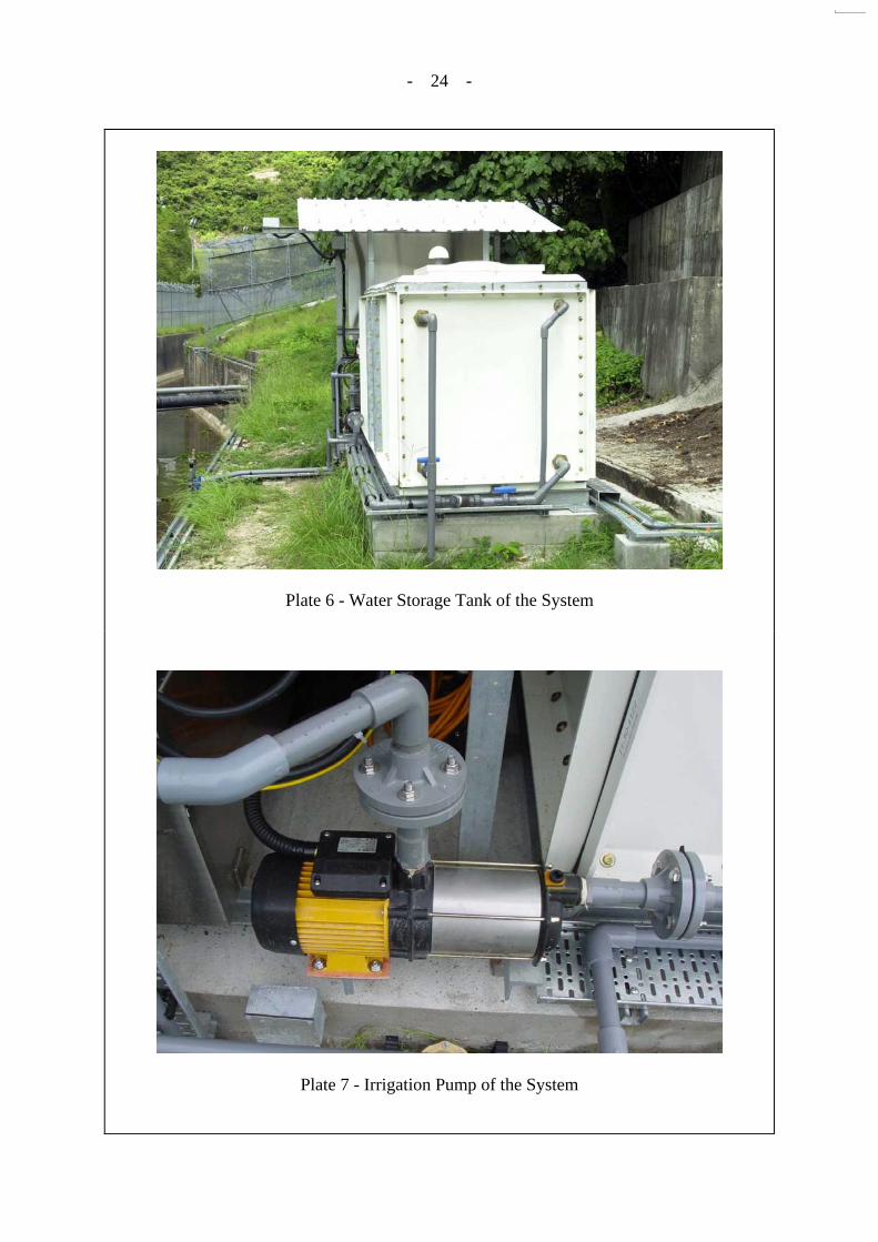
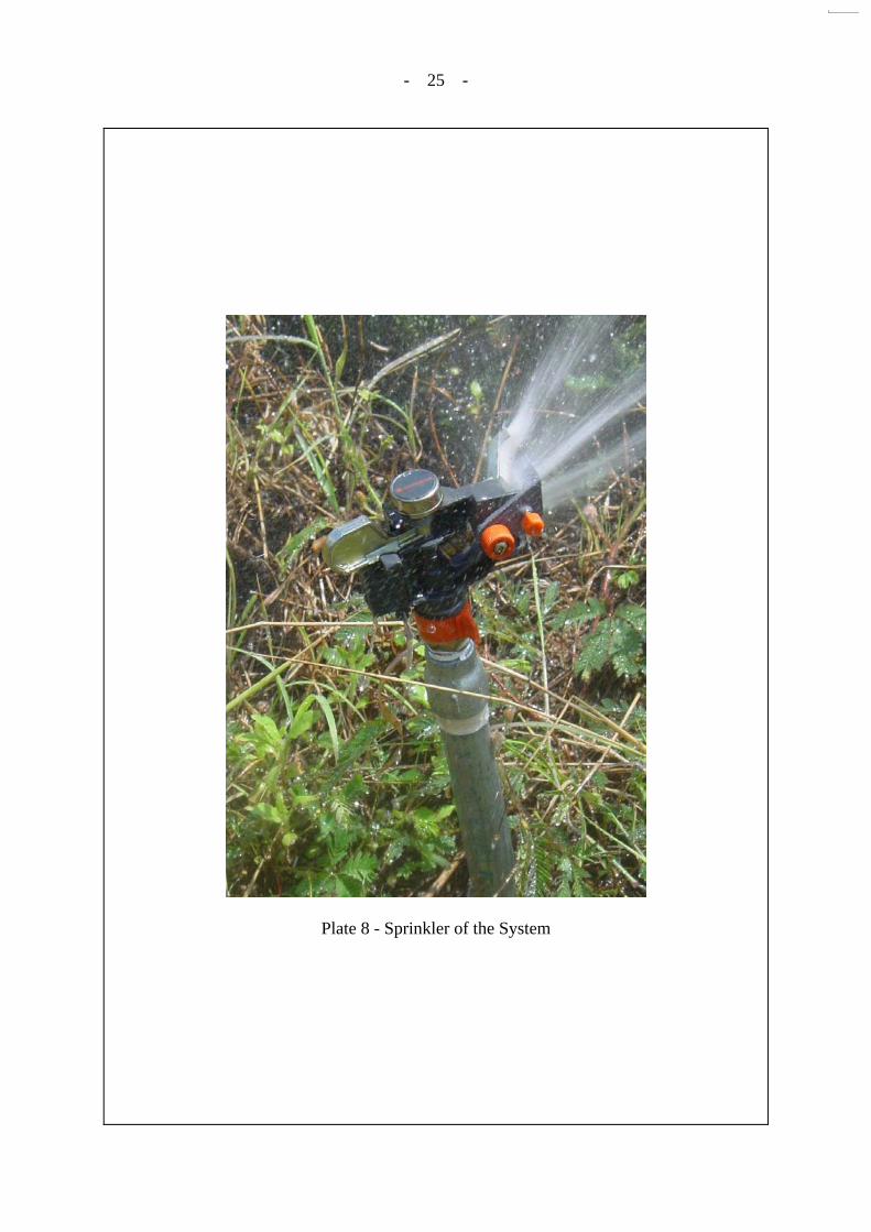
Figure 3 illustrates the schematic electric wiring layout of the whole solar power irrigation system. 4.4 Pumping and Irrigation Sub-system The pumping and irrigation sub-system comprises a submersible pump, an irrigation pump, a water storage tank, sprinklers and the associated water pipes. In the site trial, the submersible pump, which is housed in a stainless steel case, is placed in a sump pit at the junction of the natural stream course and the open channel. Plate 5 shows the submersible pump used in the system. The submersible pump pumps water to the storage tank at a specified time period as set in the control unit. It has a designed power of 450 W and is able to pump 2,000 litres of water within an hour. This power capacity takes account of the elevation difference between the pump and the storage tank, and the pressure drop along the pipeline (Stryker, 2001). The storage tank is made of glass fibre reinforced plastics. Plate 6 shows a view of the storage tank. The water stored in the tank is drawn at another specified time period by the irrigation pump through strainer and valves to the sprinklers installed at the slope toe for watering the vegetation on the slope. The power of the irrigation pump used is designed to be 1500 W. The pump is required to have the capacity of pumping 2,000 litres of water to the sprinklers within 30 to 60 minutes. Plates 7 and 8 show the irrigation pump and a sprinkler respectively. Figure 4 illustrates the schematic piping layout of the whole solar power irrigation system. Nine rotor sprinklers have been installed along the slope toe, two for zone A, three for zone B and four for zone C. The sprinklers used have a watering radius large enough to cover the distance from the toe to the crest of the slope. As the slope height of zone A is higher than that of zone B or C, the watering radius of the sprinklers required in zone A is greater and the operating pressure of the sprinklers used is also greater. Figure 2 shows the layout of the nine sprinklers used in the trial. The sprinklers in each of the three operating zones are equipped with independent timing control circuits. A plan showing the location of the PV panels, control unit and zoning of the slope is given in Figure 2. Plate 9 shows the general view of the slope with the installations of the above-mentioned system components. 5. MAINTENANCE OF THE SYSTEM
5.1 Maintenance during Defects Liability Period During the one-year defects liability period of the system, the Contractor carried out routine maintenance of the irrigation system four times on 17.10.2003, 3.2.2004, 15.6.2004 and 3.8.2004. Major items of works in each routine maintenance included:
- 10 -
(a) checking the system voltage, such as output voltages of the PV panels, batteries and inverter;
(b) cleaning the stainless steel case which houses the
submersible pump; (c) cleaning the water storage tank and the strainer; (d) cleaning the sprinklers and trimming the grass around the
sprinklers; and (e) clearing debris on the PV panels.
5.2 Maintenance after Defects Liability Period Upon the expiry of the defects liability period in July 2004, routine maintenance covering the items of works mentioned in Section 5.1 still continues at quarterly intervals. The cost of the routine maintenance including replacement of minor spare parts is about $20,000 per year. Among the components in the system, the rechargeable batteries are expected to have a relatively short life-span of about two to three years under the condition of the trial site. Once the vegetation on slope has been established to a healthy condition, normally about three to five years after planting, the system can be relocated to other sites for re-use. 6. PERFORMANCE OF THE SYSTEM During the defects liability period, two battery failures occurred, one in November 2003 and the other one in January 2004. In the first failure, the Contractor replaced one out of the eight batteries. The battery was identified to be defective. In the second failure, the Contractor replaced all the eight batteries at one time. It took about four weeks for acquiring the batteries from an overseas supplier. The irrigation system was out of operation during this time period. The irrigation system was out of operation for several times in March and April 2004. It was due to the prolonged overcast weather in these two months and high power consumption of the control unit. In May 2004, the Contractor carried out some modifications to the system to reduce the power consumption of the system and increase the system efficiency. The major modification involved revising the operation time of the AC to DC inverter. The inverter was previously switched on all day long to provide electricity for the system timer and other relays in the control unit. In order to reduce power consumption, the inverter was adjusted to operate only during the pumping and irrigation time of a day, i.e. about three hours a day. With such modifications, all the three zones were watered one by one within a day, each lasting for about 15 minutes. Extra timers and relays are added in the system to regulate this. The irrigation system has been performing satisfactorily since the modifications were made in May 2004.
- 11 -
7. CONCLUSION A solar power automatic irrigation system has been tried out on a vegetated slope at the Kau Shat Wan Explosives Depot in Lantau Island. The system had some problems at the initial operation stage. Modifications were subsequently made to improve the efficiency of the system in May 2004 and the system has been performing satisfactorily since then. If irrigation is considered necessary for a site, the use of an automatic irrigation system operated by solar power could be an option in designing the irrigation system. Relevant guidelines on water source and system design are given in Appendix A. 8. REFERENCES Leung, S.C. (2002). Feasibility Study Use of Solar Power Pump for Watering Vegetation on
Man-made Slopes. (Technical Note No. TN 1/2002). Geotechnical Engineering Office, Hong Kong, 66 p.
Stryker, S. (2001). Landscape Sprinkler Design Tutorial. http://www.IrrigationTutorials.com.

- 12 -
LIST OF TABLES Table No.
Page No.
1
Breakdown of Cost of System Equipment
13
- 13 -
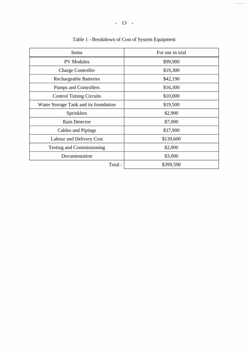
Table 1 - Breakdown of Cost of System Equipment
Items For use in trial
PV Modules $99,900
Charge Controller $19,300
Rechargeable Batteries $42,190
Pumps and Controllers $16,300
Control Timing Circuits $10,000
Water Storage Tank and its foundation $19,500
Sprinklers $2,900
Rain Detector $7,000
Cables and Pipings $37,900
Labour and Delivery Cost $139,600
Testing and Commissioning $2,000
Documentation $3,000
Total : $399,590
- 14 -
LIST OF FIGURES
Figure No.
Page No.
1
Location Plan of Slope No. 10SW-D/F75
15
2 Plan Showing Locations of System Components and Zoning of Slope
16
3 Schematic Electric Wiring Layout of the System
17
4 Schematic Piping Layout of the System
18
5 Schematic Layout of the Solar Power Automatic Irrigation System
19
- 19 -
Figure 5 - Schematic Layout of the Solar Power Automatic Irrigation System
- 20 -
LIST OF PLATES Plate No.
Page No.
1 General View of Slope No. 10SW-D/F75
21
2 Photovoltaic Panels of the System
22
3 Rechargeable Batteries of the System
22
4 Control Unit of the System
23
5 Submersible Pump of the System
23
6 Water Storage Tank of the System
24
7 Irrigation Pump of the System
24
8 Sprinkler of the System
25
9 General View of the Slope with the Installations of the System Components
26
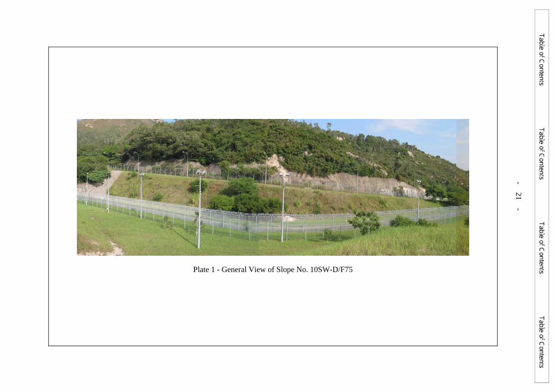
Plate 1 - General View of Slope No. 10SW-D/F75
- 21 -
- 22 -
Plate 2 - Photovoltaic Panels of the System
Plate 3 - Rechargeable Batteries of the System
- 23 -
Plate 4 - Control Unit of the System
Plate 5 - Submersible Pump of the System
- 24 -
Plate 6 - Water Storage Tank of the System
Plate 7 - Irrigation Pump of the System
- 25 -
Plate 8 - Sprinkler of the System
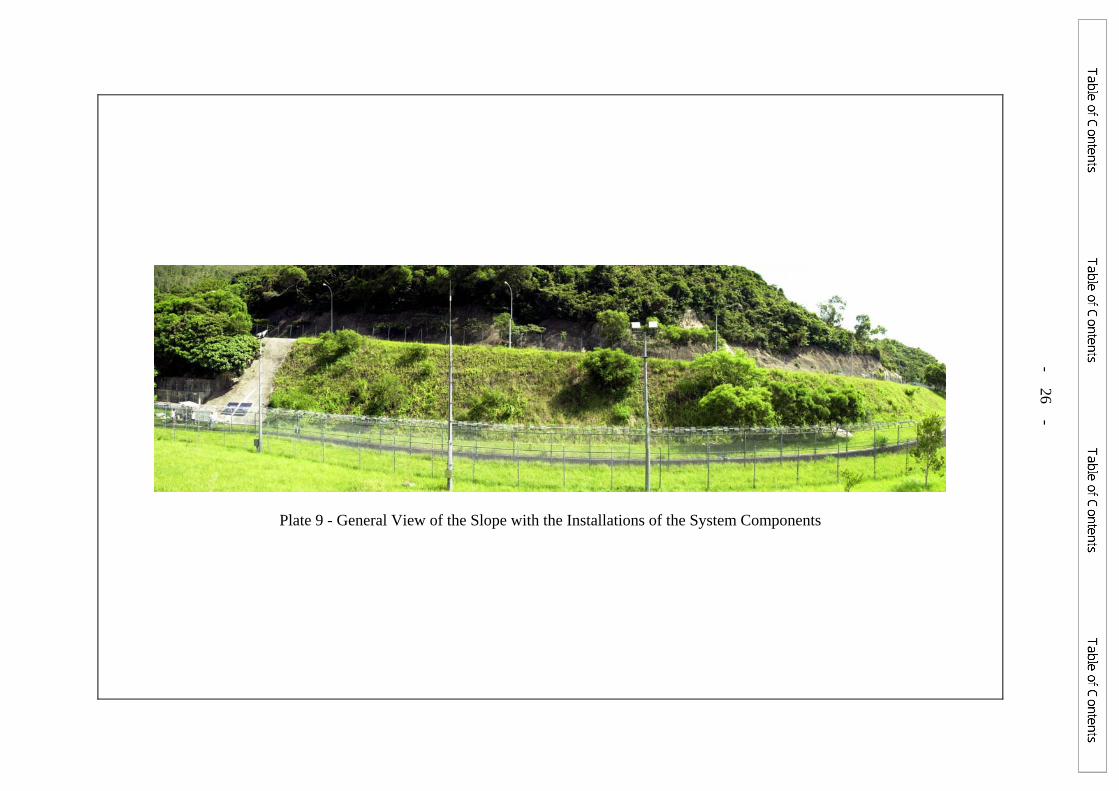
Plate 9 - General View of the Slope with the Installations of the System Components
- 26 -
- 27 -
APPENDIX A
GUIDELINES FOR DESIGN OF A SOLAR POWER AUTOMATIC IRRIGATION SYSTEM
- 28 -
CONTENTS
Page No.
CONTENTS 28 A.1 SYSTEM APPLICATIONS 29 A.2 MAJOR COMPONENTS OF A SOLAR POWER AUTOMATIC 29 IRRIGATION SYSTEM A.3 WATER SOURCE AND SITE HYDROGEOLOGY 30 A.4 SYSTEM DESIGN 30 A.5 SYSTEM MAINTENANCE 31 LIST OF FIGURES 32
- 29 -
A.1 SYSTEM APPLICATIONS A solar power automatic irrigation system will be applicable to slopes which satisfy the following criteria:
(a) Slopes are located in remote area where water and electricity supply is not readily available in their vicinity or slopes are located along expressways where parking or slowing down of vehicles for watering is not allowed;
(b) Slopes are located in an open area with adequate space for
accommodating the photovoltaic (PV) panels, battery and water tank, and without being shaded from sunshine for the PV panels to work;
(c) Water source is available such as presence of nearby natural
stream course or shallow groundwater source; and (d) No excessive settlement of ground/structures nearby is
envisaged as a result of groundwater drawdown in case groundwater is to be extracted.
A.2 MAJOR COMPONENTS OF A SOLAR POWER AUTOMATIC IRRIGATION
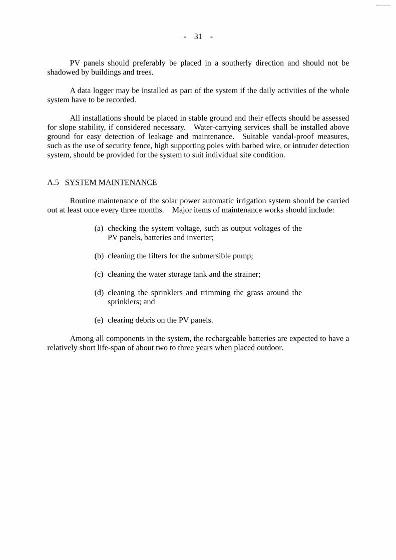
SYSTEM The solar power automatic irrigation system should in general comprise three sub-systems: (a) solar power sub-system; (b) electrical control sub-system; and (c) pumping and irrigation system. A typical layout of the sub-systems is shown in Figure A1. The major components of the sub-systems are outlined below.
(a) Solar Power Sub-system This sub-system is responsible for generating electrical
power from solar power, and supplying electrical power for the operation of the whole irrigation system. Major components of the sub-system may include PV panels, rechargeable batteries (optional), charger and necessary accessories. The sub-system should be of enough capacity to provide electrical power necessary for operating the whole automatic irrigation system.
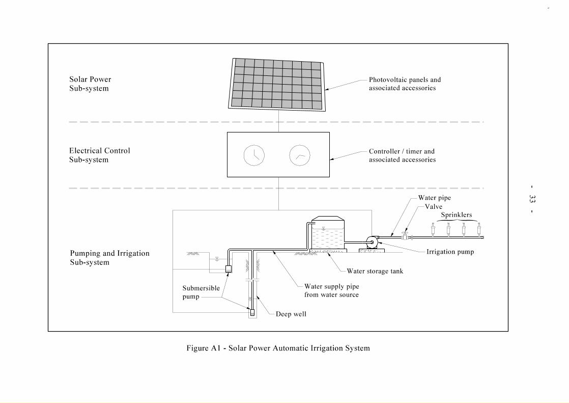
(b) Electrical Control Sub-system This sub-system controls the charging of batteries and the
timing for operation of pumps and sprinklers. Major components of the sub-system may include electrical timers, automatic controllers, charge controller, inverter and rain detector. A typical schematic electric wiring layout is
- 30 -
illustrated in Figure A2. (c) Pumping and Irrigation Sub-system This sub-system deals with the extraction of water,
temporary storage of the water and irrigation of vegetation. Major components of the sub-system may include a submersible water pump, an irrigation pump, a water storage tank, sprinklers and associated water pipes. The sub-system should be of sufficient capacity to provide water necessary for irrigation of vegetation on slope.
The irrigation system should be designed and installed in such a way that most of the system components can be re-used at other sites. A.3 WATER SOURCE AND SITE HYDROGEOLOGY If groundwater is to be used for irrigation, pump well(s) should be provided for extracting the groundwater. The hydrogeological condition of the area where the pump well is to be installed should be determined. The size and depth of the pump well should be carefully designed to ensure that the well can provide sufficient yield even in dry seasons when the water table is low. A careful assessment should also be carried out to estimate the groundwater drawdown, the associated settlement and the probable effects to nearby services, buildings or structures. A field test may also be required to determine the yield of the well. Alternative water source using water supply from the Water Supplies Department may be considered if the supply is readily available to the site. A cost comparison of this option with the one of extracting groundwater or water from natural stream course should be carried out. Horticultural advice should be sought on the watering requirement for the vegetation planted on the slope. A.4 SYSTEM DESIGN Design of the electrical and mechanical equipment and systems for the solar power automatic irrigation system should be carried out by competent engineers, with input from geotechnical engineer on aspects such as depth of pump well, groundwater drawdown and settlement. The design shall be in accordance with the latest version of the relevant standards and statutory regulations, and supported with design calculations. The designer shall decide the minimum number of days for which the system can still be effective operation in case of overcast weather such that the rechargeable batteries should be designed accordingly to store the required back-up power for the system use on the overcast days. If it is intended to directly consume the solar power generated from the PV panels, rechargeable batteries may not be required. This will reduce the total system cost, but the system can only operate during sunny periods.
- 31 -
PV panels should preferably be placed in a southerly direction and should not be shadowed by buildings and trees. A data logger may be installed as part of the system if the daily activities of the whole system have to be recorded. All installations should be placed in stable ground and their effects should be assessed for slope stability, if considered necessary. Water-carrying services shall be installed above ground for easy detection of leakage and maintenance. Suitable vandal-proof measures, such as the use of security fence, high supporting poles with barbed wire, or intruder detection system, should be provided for the system to suit individual site condition. A.5 SYSTEM MAINTENANCE Routine maintenance of the solar power automatic irrigation system should be carried out at least once every three months. Major items of maintenance works should include:
(a) checking the system voltage, such as output voltages of the PV panels, batteries and inverter;
(b) cleaning the filters for the submersible pump; (c) cleaning the water storage tank and the strainer; (d) cleaning the sprinklers and trimming the grass around the
sprinklers; and (e) clearing debris on the PV panels.
Among all components in the system, the rechargeable batteries are expected to have a relatively short life-span of about two to three years when placed outdoor.

- 32 -
LIST OF FIGURES
Figure No.
Page No.
A1
Solar Power Automatic Irrigation System
33
A2
Schematic Electric Wiring Layout of the System
34
GEO PUBLICATIONS AND ORDERING INFORMATION 土力工程處刊物及訂購資料
A selected list of major GEO publications is given in the next page. An up-to-date full list of GEO publications can be found at the CEDD Website http://www.cedd.gov.hk on the Internet under “Publications”. Abstracts for the documents can also be found at the same website. Technical Guidance Notes are published on the CEDD Website from time to time to provide updates to GEO publications prior to their next revision.
部份土力工程處的主要刊物目錄刊載於下頁。而詳盡及最新的
土力工程處刊物目錄,則登載於土木工程拓展署的互聯網網頁
http://www.cedd.gov.hk 的“刊物”版面之內。刊物的摘要及更新
刊物內容的工程技術指引,亦可在這個網址找到。
Copies of GEO publications (except maps and other publications which are free of charge) can be purchased either by:
讀者可採用以下方法購買土力工程處刊物(地質圖及免費刊物
除外):
writing to Publications Sales Section, Information Services Department, Room 402, 4th Floor, Murray Building, Garden Road, Central, Hong Kong. Fax: (852) 2598 7482
書面訂購
香港中環花園道
美利大廈4樓402室
政府新聞處
刊物銷售組
傳真: (852) 2598 7482
or 或 − Calling the Publications Sales Section of Information Services
Department (ISD) at (852) 2537 1910 − Visiting the online Government Bookstore at
http://bookstore.esdlife.com − Downloading the order form from the ISD website at
http://www.isd.gov.hk and submit the order online or by fax to (852) 2523 7195
− Placing order with ISD by e-mail at [email protected]
− 致電政府新聞處刊物銷售小組訂購 (電話:(852) 2537 1910)
− 進入網上「政府書店」選購,網址為 http://bookstore.esdlife.com
− 透過政府新聞處的網站 (http://www.isd.gov.hk) 於網上遞
交訂購表格,或將表格傳真至刊物銷售小組 (傳真:(852)
2523 7195)
− 以電郵方式訂購 (電郵地址:[email protected])
1:100 000, 1:20 000 and 1:5 000 maps can be purchased from:
讀者可於下列地點購買1:100 000,1:20 000及1:5 000地質圖:
Map Publications Centre/HK, Survey & Mapping Office, Lands Department, 23th Floor, North Point Government Offices, 333 Java Road, North Point, Hong Kong. Tel: 2231 3187 Fax: (852) 2116 0774
香港北角渣華道333號
北角政府合署23樓
地政總署測繪處
電話: 2231 3187
傳真: (852) 2116 0774
Requests for copies of Geological Survey Sheet Reports, publications and maps which are free of charge should be sent to:
如欲索取地質調查報告、其他免費刊物及地質圖,請致函:
For Geological Survey Sheet Reports and maps which are free of charge: Chief Geotechnical Engineer/Planning, (Attn: Hong Kong Geological Survey Section) Geotechnical Engineering Office, Civil Engineering and Development Department, Civil Engineering and Development Building, 101 Princess Margaret Road, Homantin, Kowloon, Hong Kong. Tel: (852) 2762 5380 Fax: (852) 2714 0247 E-mail: [email protected]
地質調查報告及地質圖:
香港九龍何文田公主道101號
土木工程拓展署大樓
土木工程拓展署
土力工程處
規劃部總土力工程師
(請交:香港地質調查組)
電話: (852) 2762 5380
傳真: (852) 2714 0247
電子郵件: [email protected]
For other publications which are free of charge: Chief Geotechnical Engineer/Standards and Testing, Geotechnical Engineering Office, Civil Engineering and Development Department, Civil Engineering and Development Building, 101 Princess Margaret Road, Homantin, Kowloon, Hong Kong. Tel: (852) 2762 5345 Fax: (852) 2714 0275 E-mail: [email protected]
其他免費刊物:
香港九龍何文田公主道101號
土木工程拓展署大樓
土木工程拓展署
土力工程處
標準及測試部總土力工程師
電話: (852) 2762 5345
傳真: (852) 2714 0275
電子郵件: [email protected]
MAJOR GEOTECHNICAL ENGINEERING OFFICE PUBLICATIONS 土力工程處之主要刊物
GEOTECHNICAL MANUALS Geotechnical Manual for Slopes, 2nd Edition (1984), 300 p. (English Version), (Reprinted, 2000).
斜坡岩土工程手冊(1998),308頁(1984年英文版的中文譯本)。
Highway Slope Manual (2000), 114 p. GEOGUIDES Geoguide 1 Guide to Retaining Wall Design, 2nd Edition (1993), 258 p. (Reprinted, 2000).
Geoguide 2 Guide to Site Investigation (1987), 359 p. (Reprinted, 2000).
Geoguide 3 Guide to Rock and Soil Descriptions (1988), 186 p. (Reprinted, 2000).
Geoguide 4 Guide to Cavern Engineering (1992), 148 p. (Reprinted, 1998).
Geoguide 5 Guide to Slope Maintenance, 3rd Edition (2003), 132 p. (English Version).
岩土指南第五冊 斜坡維修指南,第三版(2003),120頁(中文版)。
Geoguide 6 Guide to Reinforced Fill Structure and Slope Design (2002), 236 p. GEOSPECS Geospec 1 Model Specification for Prestressed Ground Anchors, 2nd Edition (1989), 164 p. (Reprinted,
1997).
Geospec 3 Model Specification for Soil Testing (2001), 340 p. GEO PUBLICATIONS GCO Publication No. 1/90
Review of Design Methods for Excavations (1990), 187 p. (Reprinted, 2002).
GEO Publication No. 1/93
Review of Granular and Geotextile Filters (1993), 141 p.
GEO Publication No. 1/2000
Technical Guidelines on Landscape Treatment and Bio-engineering for Man-made Slopes and Retaining Walls (2000), 146 p.
GEO Publication No. 1/2006
Foundation Design and Construction (2006), 376 p.
GEOLOGICAL PUBLICATIONS The Quaternary Geology of Hong Kong, by J.A. Fyfe, R. Shaw, S.D.G. Campbell, K.W. Lai & P.A. Kirk (2000),210 p. plus 6 maps.
The Pre-Quaternary Geology of Hong Kong, by R.J. Sewell, S.D.G. Campbell, C.J.N. Fletcher, K.W. Lai & P.A.Kirk (2000), 181 p. plus 4 maps. TECHNICAL GUIDANCE NOTES TGN 1 Technical Guidance Documents